JP4896143B2 - Burner, combustion apparatus equipped with burner, and boiler - Google Patents
Burner, combustion apparatus equipped with burner, and boiler Download PDFInfo
- Publication number
- JP4896143B2 JP4896143B2 JP2008536284A JP2008536284A JP4896143B2 JP 4896143 B2 JP4896143 B2 JP 4896143B2 JP 2008536284 A JP2008536284 A JP 2008536284A JP 2008536284 A JP2008536284 A JP 2008536284A JP 4896143 B2 JP4896143 B2 JP 4896143B2
- Authority
- JP
- Japan
- Prior art keywords
- fuel
- containing fluid
- burner
- furnace
- supply nozzle
- Prior art date
- Legal status (The legal status is an assumption and is not a legal conclusion. Google has not performed a legal analysis and makes no representation as to the accuracy of the status listed.)
- Active
Links
- 238000002485 combustion reaction Methods 0.000 title claims description 83
- 239000000446 fuel Substances 0.000 claims description 360
- 239000012530 fluid Substances 0.000 claims description 349
- XLYOFNOQVPJJNP-UHFFFAOYSA-N water Substances O XLYOFNOQVPJJNP-UHFFFAOYSA-N 0.000 claims description 27
- 239000004449 solid propellant Substances 0.000 claims description 9
- 239000003381 stabilizer Substances 0.000 claims description 5
- 239000007788 liquid Substances 0.000 claims description 3
- 239000006163 transport media Substances 0.000 claims description 2
- 238000004804 winding Methods 0.000 claims description 2
- MWUXSHHQAYIFBG-UHFFFAOYSA-N Nitric oxide Chemical compound O=[N] MWUXSHHQAYIFBG-UHFFFAOYSA-N 0.000 description 90
- 239000000567 combustion gas Substances 0.000 description 21
- 230000000694 effects Effects 0.000 description 18
- 239000007789 gas Substances 0.000 description 10
- 239000006185 dispersion Substances 0.000 description 7
- 230000007423 decrease Effects 0.000 description 5
- 230000001737 promoting effect Effects 0.000 description 4
- 230000005855 radiation Effects 0.000 description 4
- 238000011144 upstream manufacturing Methods 0.000 description 4
- 230000015572 biosynthetic process Effects 0.000 description 2
- 239000003245 coal Substances 0.000 description 2
- 230000002093 peripheral effect Effects 0.000 description 2
- 230000001629 suppression Effects 0.000 description 2
- 239000002028 Biomass Substances 0.000 description 1
- 239000012141 concentrate Substances 0.000 description 1
- 230000001934 delay Effects 0.000 description 1
- 229910003460 diamond Inorganic materials 0.000 description 1
- 239000010432 diamond Substances 0.000 description 1
- 238000000034 method Methods 0.000 description 1
- 238000000926 separation method Methods 0.000 description 1
Images


Classifications
-
- F—MECHANICAL ENGINEERING; LIGHTING; HEATING; WEAPONS; BLASTING
- F23—COMBUSTION APPARATUS; COMBUSTION PROCESSES
- F23D—BURNERS
- F23D1/00—Burners for combustion of pulverulent fuel
- F23D1/005—Burners for combustion of pulverulent fuel burning a mixture of pulverulent fuel delivered as a slurry, i.e. comprising a carrying liquid
-
- F—MECHANICAL ENGINEERING; LIGHTING; HEATING; WEAPONS; BLASTING
- F23—COMBUSTION APPARATUS; COMBUSTION PROCESSES
- F23D—BURNERS
- F23D1/00—Burners for combustion of pulverulent fuel
-
- F—MECHANICAL ENGINEERING; LIGHTING; HEATING; WEAPONS; BLASTING
- F22—STEAM GENERATION
- F22B—METHODS OF STEAM GENERATION; STEAM BOILERS
- F22B1/00—Methods of steam generation characterised by form of heating method
- F22B1/02—Methods of steam generation characterised by form of heating method by exploitation of the heat content of hot heat carriers
- F22B1/18—Methods of steam generation characterised by form of heating method by exploitation of the heat content of hot heat carriers the heat carrier being a hot gas, e.g. waste gas such as exhaust gas of internal-combustion engines
- F22B1/1869—Hot gas water tube boilers not provided for in F22B1/1807 - F22B1/1861
-
- F—MECHANICAL ENGINEERING; LIGHTING; HEATING; WEAPONS; BLASTING
- F22—STEAM GENERATION
- F22B—METHODS OF STEAM GENERATION; STEAM BOILERS
- F22B21/00—Water-tube boilers of vertical or steeply-inclined type, i.e. the water-tube sets being arranged vertically or substantially vertically
- F22B21/22—Water-tube boilers of vertical or steeply-inclined type, i.e. the water-tube sets being arranged vertically or substantially vertically built-up from water tubes of form other than straight or substantially straight
- F22B21/26—Water-tube boilers of vertical or steeply-inclined type, i.e. the water-tube sets being arranged vertically or substantially vertically built-up from water tubes of form other than straight or substantially straight bent helically, i.e. coiled
-
- F—MECHANICAL ENGINEERING; LIGHTING; HEATING; WEAPONS; BLASTING
- F23—COMBUSTION APPARATUS; COMBUSTION PROCESSES
- F23C—METHODS OR APPARATUS FOR COMBUSTION USING FLUID FUEL OR SOLID FUEL SUSPENDED IN A CARRIER GAS OR AIR
- F23C99/00—Subject-matter not provided for in other groups of this subclass
-
- F—MECHANICAL ENGINEERING; LIGHTING; HEATING; WEAPONS; BLASTING
- F23—COMBUSTION APPARATUS; COMBUSTION PROCESSES
- F23D—BURNERS
- F23D2201/00—Burners adapted for particulate solid or pulverulent fuels
- F23D2201/10—Nozzle tips
-
- F—MECHANICAL ENGINEERING; LIGHTING; HEATING; WEAPONS; BLASTING
- F23—COMBUSTION APPARATUS; COMBUSTION PROCESSES
- F23D—BURNERS
- F23D2201/00—Burners adapted for particulate solid or pulverulent fuels
- F23D2201/20—Fuel flow guiding devices
Description
【技術分野】
【0001】
本発明は、バーナ、該バーナを備えた燃焼装置、及びボイラに関し、特に、効率の良い低窒素酸化物(NOx)燃焼が可能な前記バーナに関する。
【背景技術】
【0002】
図28に従来技術からなる固体燃料(微粉炭、バイオマス燃料など)用バーナの例を示す。図28(a)はバーナの側断面図、図28(b)は該バーナを火炉(4)側から見た正面図である。この固体燃料用バーナは固体燃料と搬送用一次空気とを含む燃料含有流体(11)が火炉(4)に向かって流れる燃料含有流体流路を画定している燃料含有流体供給ノズル(12)と、該燃料含有流体供給ノズル(12)の外周に設けられた燃焼用空気スリーブ(15)とを備え、風箱(3)内の空気が前記スリーブ(15)により画定された燃焼用空気流路を通して、二次空気(13)及び三次空気(14)として供給される。燃料含有流体供給ノズル(12)の先端には保炎器(17)が設けられており、その後流に形成される循環渦の効果でバーナ近傍からの燃料の着火を可能としている。
【0003】
燃焼用空気スリーブ(15)の先端は、火炉壁面に設けられたバーナスロート(16)に臨む位置にあり、該スリーブ(15)の先端にはバーナの外側に広がる燃焼用空気案内板(15a)が設けられており、三次空気(14)は該燃焼用空気案内板(15a)により外側に広げられ、火炎中心部への空気の混合を遅らせ、空気不足の還元雰囲気条件下での燃焼促進により、燃焼ガス中の窒素酸化物(NOx)の生成を抑制している。
【0004】
図1(c)に前記従来技術のバーナにおける燃料含有流体供給ノズル(12)の燃料含有流体(11)の噴出流に沿った方向の断面図を示し、図1(d)に図1(c)のバーナの燃料含有流体供給ノズル(12)の出口部を火炉(4)側から見た正面図を示すように、従来技術のバーナでは、燃料含有流体供給ノズル(12)の出口部の断面は円形に近い形状を有している。燃料含有流体(11)が火炉(4)内に投入されると、火炉(4)内の輻射による加熱や保炎器(17)の後流の循環渦の働きで燃料含有流体供給ノズル(12)の出口近傍で燃料に着火される。
【0005】
図29(a)に従来技術のバーナにおける燃料含有流体供給ノズル(12)の燃料含有流体(11)の噴出流に沿った方向の断面図を示し、図29(b)に該燃料含有流体供給ノズル(12)の出口部を火炉(4)側から見た正面図を示すように、燃料含有流体供給ノズル(12)から火炉(4)内に噴出する燃料含有流体中の燃料の着火位置(33)が形成される。燃料含有流体(11)の噴流の表面で燃料が着火した後、形成される火炎は次第に燃料含有流体(11)の噴流の中心部に向かって伝播する。図30は従来技術のバーナにおける燃料含有流体供給ノズル(12)の燃料含有流体(11)の噴出流に沿った断面方向の火炉(4)内の火炎伝播の挙動を模式的に示したものである。円錐形状の未着火領域(31)の周りに着火領域(32)が形成される。
【0006】
上記図28〜図30に示す断面円形のバーナは、対向する一対の火炉壁にそれぞれ配置される、いわゆる対向燃焼方式に用いられることが多い。一方、火炉壁面に沿って複数の燃料含有流体供給ノズル(12)の出口から火炉(4)内に旋回を与える方向に前記燃料含有流体を噴出させながら燃料を燃焼させる、いわゆるタンジェンシャル燃焼においては、燃料含有流体供給ノズル(12)の横断面(燃料含有流体流れに直交する断面)の出口形状を正方形または正方形に近い矩形とすることが多い。
【0007】
また、前記燃料含有流体供給ノズル(12)の横断面(燃料含有流体流れに直交する断面)の出口形状を長径部と短径部を有する矩形状、楕円形状又は略楕円形状とするバーナは下記特許文献1〜3に開示されている。
【特許文献1】
特表昭59−500981号公報
【特許文献2】
特開平8−226615号公報
【特許文献3】
特開平11−281009号公報
【発明の開示】
【発明が解決しようとする課題】
【0008】
一般にバーナの燃料含有流体供給ノズル(12)の出口部の断面は円形又は正方形に近い形状をしており、図30に示すように、火炉(4)内において燃料含有流体噴流の外側で着火した火炎が燃料含有流体噴流の中心部まで伝播するにはかなりの距離を必要とする場合がある。燃料含有流体供給ノズル(12)からの燃料含有流体(11)の噴出流方向における着火した火炎が燃料噴流の中心部まで伝播する距離、すなわち、図30に示す未着火距離L1’は、燃料含有流体供給ノズル(12)の直径又は周辺部が大きくなるほど長くなり、未着火領域(31)が拡大する。バーナ近傍の還元領域で燃焼を促進することが、燃焼ガス中でのNOx発生を抑制する上で重要であるが、未着火領域(31)の拡大は、このNOx濃度の抑制の特性を阻害することになる。また、未着火領域(31)の拡大は着火後の燃焼時間が短くなることを意味し、燃焼効率低下の要因ともなる。
【0009】
バーナ容量の増加(バーナ本数の低減)はコスト低減と運用性向上のために有効な手法であるが、従来技術においては、バーナ容量が増加すると燃料含有流体供給ノズル(12)の直径又は外径部の長さが長くなり、未着火領域(31)が拡大して、NOxの増加と燃焼効率の低下の原因となる問題点があった。この問題は、燃料含有流体噴流表面の着火領域(32)から燃料含有流体噴流の中心部までの距離が大きいことが原因であった。また、前記特許文献1〜3記載の燃料含有流体供給ノズル(12)の横断面(燃料含有流体流れに直交する断面)の出口形状を長径部と短径部の組み合わせからなる矩形状などとした発明では、バーナ容量の増加により未着火領域(31)が拡大して、NOxの増加と燃焼効率の低下が生じることに対する対策については何ら触れられてない。
【0010】
本発明の課題は容量を従来より増加させながら、未着火領域の拡大を抑え、燃焼ガス中のNOx濃度の増加防止と燃焼効率低下防止を図った固体燃料用バーナ、該バーナを備えた燃焼装置及びボイラを提供することである。
【課題を解決するための手段】
【0011】
上記本発明の課題は次の解決手段で解決される。
請求項1記載の発明は、固体燃料と該燃料搬送用媒体の燃料含有流体(11)を搬送する燃料含有流体搬送流路(10)の接続部(10a)から火炉(4)壁面に設けた出口部に向けて前記流体(11)を供給する燃料含有流体供給ノズル(12)と、該燃料含有流体供給ノズル(12)の外周部に一以上の燃焼用空気を供給する空気供給ノズル(15)を有するバーナにおいて、前記燃料含有流体供給ノズル(12)は、前記流体搬送流路(10)の接続部(10a)から火炉(4)の壁面に設けた出口部に向けて流体(11)の流れに直交する断面を長径部と短径部を有する矩形状、楕円形状又は略楕円形状とし、前記流体搬送流路(10)の接続部(10a)から出口部に向けて流体(11)の流れに直交する断面の長径部の大きさが流体(11)の流れ方向に沿って次第に拡大し、短径部の大きさが不変である構成を有するバーナである。
[0012]
[0013]
【0014】
請求項2記載の発明は、前記燃料含有流体供給ノズル(12)が、その内部に燃料含有流体(11)の流れを複数に分割する燃料含有流体案内板(19)を有する請求項1記載のバーナである。
【0015】
請求項3記載の発明は、前記燃料含有流体案内板(19)が、燃料含有流体供給ノズル(12)内の流体(11)の流れ方向の中心軸を火炉(4)内に延長した線上を通り、該ノズル(12)の短径部の最短径を通る平面に平行な平面に対して複数の異なる傾斜角度で配置した請求項2記載のバーナである。
【0016】
請求項4記載の発明は、前記燃料含有流体供給ノズル(12)が、その出口内部に燃料含有流体(11)の噴出流れ方向を強制的に変更する燃料含有流体向き変更用案内板(21)を有する請求項1〜3のいずれかに記載のバーナである。
【0017】
請求項5記載の発明は、前記燃料含有流体向き変更用案内板(21)が、燃料含有流体供給ノズル(12)の中心軸を火炉(4)内に延長した線上を通り、該ノズル(12)の長径部の最長径を通る平面に平行な平面に対して、互いに異なる複数の向きに配置される請求項4記載のバーナである。
【0018】
請求項6記載の発明は、前記燃料含有流体向き変更用案内板(21)が、一部の燃料含有流体(11)については燃料含有流体供給ノズル(12)の中心軸を火炉(4)内に延長した線上を通り、該ノズル(12)の長径部の最長径を通る平面に平行な平面に対して平行に配置され、その他の燃料含有流体(11)については燃料含有流体供給ノズル(12)の中心軸を火炉(4)内に延長した線上を通り、該ノズル(12)の長径部の最長径を通る平面に平行な平面に対して傾斜角度を持たせて配置される請求項4記載のバーナである。
【0019】
請求項7記載の発明は、前記燃料含有流体供給ノズル(12)が、前記燃料含有流体案内板(19)で複数個の流路に仕切られて、前記各流路の中心軸が燃料含有流体供給ノズル(12)の中心軸を火炉(4)内に延長した線上を通り、該ノズル(12)出口の長径部の最長径を通る平面に平行な平面に対して互いに異なる傾斜角度で火炉(4)の壁面に設けられている請求項2記載のバーナである。
【0020】
請求項8記載の発明は、前記燃料含有流体供給ノズル(12)の出口部に、該出口部を複数に分割可能な燃料含有流体分割板(22)を設けた請求項1〜7のいずれかに記載のバーナである。
【0021】
請求項9記載の発明は、前記燃料含有流体供給ノズル(12)の出口部に断面L字型の保炎器(17)を設けた請求項1〜8のいずれかに記載のバーナである。
【0022】
請求項10記載の発明は、前記L字型の保炎器(17)の先端に、該保炎器(17)周囲の燃焼用空気の噴出方向を外側に変える案内板(17a)を設けた請求項9記載のバーナである。
【0023】
請求項11記載の発明は、該ノズル(12)の外周部に配置される一以上の燃焼用空気供給ノズル(15)の外側の燃焼用空気の噴出方向を燃料噴出方向に対して外側に広げる燃焼用空気案内板(15a)を前記燃焼用空気供給ノズル(15)の先端に設けた請求項1〜10のいずれかに記載のバーナである。
【0024】
請求項12記載の発明は、前記燃料含有流体供給ノズル(12)の内部に、燃料含有流体(11)の流路を一旦狭くした後、再び流路を拡大する濃縮器(23)を設けた請求項1〜11のいずれかに記載のバーナである。
【0025】
請求項13記載の発明は、前記燃料含有流体供給ノズル(12)の入口部に、該ノズル(12)内で燃料を均等に分配する流体分配板(24)を設けた請求項1〜12のいずれかに記載のバーナである。
【0026】
請求項14記載の発明は、前記燃料含有流体供給ノズル(12)から噴出する流体(11)の近傍に補助燃料である液体燃料又は気体燃料を噴出するノズル(41、44)を燃料含有流体供給ノズル(12)近傍に設けた請求項1〜13のいずれかに記載のバーナである。
【0027】
請求項15記載の発明は、請求項1〜14記載のバーナを対向する2つの火炉壁にそれぞれ上下方向に複数段配置し、各段に設けられる複数のバーナは同一火炉壁の水平方向の幅の中央部で二分した壁面領域にそれぞれ対称的に配置する燃焼装置である。
【0028】
請求項16記載の発明は、請求項1〜14記載のバーナを対向する2つの火炉壁にそれぞれ上下方向に複数段配置し、同一火炉壁の各段に設けられる複数のバーナの中で水平方向の隣接するバーナ同士は同一構造のバーナとする燃焼装置である。
【0029】
請求項17記載の発明は、水平に対して斜め向きの水壁管(25)をスパイラル状に巻き付けて構成される火炉壁を備えたボイラにおいて、前記水壁管(25)の長手方向に沿って矩形状、楕円形状又は略楕円形状の開口部(26)を火炉壁に設け、請求項1〜14のいずれかに記載のバーナを前記開口部(26)に取り付けるボイラである。
【0030】
請求項18記載の発明は、鉛直方向に伸びた水壁管(25)群から構成される火炉壁を備えたボイラにおいて、前記水壁管(25)の長手方向に沿って矩形状、楕円形状又は略楕円形状の開口部(26)を火炉壁に設け、請求項1〜14のいずれかに記載のバーナを前記開口部(26)に取り付けるボイラである。
発明の効果
[0031]
請求項1記載の発明によれば、バーナ容量が増加しても未着火領域の拡大を抑えることが可能となり、燃料含有流体(11)が火炉(4)内に投入された後も燃料含有流体(11)は幅方向に広がり、燃料含有流体(11)の噴出流の断面積が拡大して流速が低下するので、未着火距離を従来技術に比較して縮小させるのに有効であり、また、燃料含有流体(11)が火炉(4)内で広がるため、燃焼空間を有効に活用できるとともに、実質の炉内滞留時間が長くなり、燃焼ガス中のNOx濃度の低減と燃焼効率向上の効果がある。また、燃料含有流体供給ノズル(12)の前記短径部の大きさが不変であるため、構造の簡素化に有効である。また、燃料含有流体供給ノズル(12)の上流側流速を高く出来るので、着火しやすい燃料の場合などにおいて、逆火防止にも有効である。
[0032]
[0033]
【0034】
請求項2、3記載の発明によれば、燃料含有流体供給ノズル(12)の内部の燃料
含有流体案内板(19)により燃料含有流体(11)の流れが複数に分割されるので、燃料含有流体接続部(10a)から燃料含有流体供給ノズル(12)の出口部に向けて燃料含有流体(11)がノズル(12)の拡大する方向に均等に供給され、NOxの低減、燃焼効率の向上、流速増加の抑制、圧力損失の最小化、及び構成部品の摩耗抑制効果が請求項1記載の発明より、一層良くなる。
【0035】
請求項4記載の発明によれば、燃料含有流体噴出流(20)の火炉(4)内での分散が促進され、火炉(4)後流部での燃焼が促進される効果を有する。
【0036】
請求項5記載の発明によれば、燃料含有流体案内板(19)は、燃料含有流体供給ノズル(12)の中心軸を火炉(4)内に延長した線上を通り、該ノズル(12)の長径部の最長径を通る平面に平行な平面に対して互いに相反する向きにそれぞれ配置されているので、2つ以上のグループに分けて燃料含有流体(11)を火炉(4)内に噴出させることができ、簡素な構造で燃料含有流体噴出流(20)のグループ分けを行い、燃料含有流体噴出流(20)の火炉(4)内での分散が促進され、火炉(4)の後流部での燃焼が促進される効果を有する。
【0037】
請求項6記載の発明によれば、燃料含有流体供給ノズル(12)と燃料含有流体案内板(19)とで形成された4つの燃料含有流体噴出流(20)を2つのグループ(20a、20b)に分けて、例えば、火炉側壁寄りの燃料含有流体噴出流(20a)を直進流とし、火炉側壁寄りでない燃料含有流体噴出流(20b)を水平方向に傾斜を与えて噴出させることで、燃料の分散による火炉後流部での燃焼促進を維持しつつ、火炉側壁近傍への火炎流入を抑えて灰付着を防止する効果がある。
【0038】
請求項7記載の発明によれば、燃料含有流体供給ノズル(12)から水平方向又は鉛直方向に対して互いに異なる傾斜角度を持って燃料含有流体(11)を火炉(4)内に噴出させることができ、微粉炭などの固体燃料が直接衝突する燃料含有流体供給ノズル(12)内の部品を用いることなく燃料含有流体噴出流(20)の向きを変化させることが出来るので、部品の摩耗抑制に有効である。
【0039】
請求項8記載の発明によれば、燃料含有流体分割板(22)によって燃料含有流体噴出流(20)が分割され、表面積が拡大して火炉(4)内の輻射受熱が増大するとともに、流体分割板(22)の後流側に負圧領域が形成されて周囲の高温ガスが負圧領域に流れ込み、燃料への早期着火に寄与し、バーナ近傍の還元領域での燃焼が促進されて、燃焼ガスのNOx濃度の低減と燃焼効率向上に有効に作用する。
【0040】
請求項9記載の発明によれば、燃料含有流体供給ノズル(12)の出口部に断面L字型の保炎器(17)を設けたことにより、保炎器(17)の後流には循環渦が形成されて高温の燃焼ガスを保炎器(17)の近傍に引き戻すため、燃料への早期着火に寄与し、バーナ近傍の還元領域での燃焼が促進されて、燃焼ガスのNOx濃度の低減と燃焼効率向上に有効に作用する。
【0041】
請求項10記載の発明によれば、断面L字型の保炎器(17)の先端の二次空気案内板(17a)により、二次空気が外側に広がり、保炎器(17)の後流の循環渦が大きくなり、高温の燃焼ガスの再循環量が増加し、請求項9記載の発明に比較して燃料への着火をさらに早めて、バーナ近傍の還元領域での燃焼が促進され、燃焼ガスのNOx濃度の低減と燃焼効率向上に有効に作用する。
【0042】
請求項11記載の発明によれば、燃焼用空気供給ノズル(15)の外側の燃焼用空気噴出向きを燃料含有流体噴出方向に対して外側に広げる燃焼用空気案内板(15a)を設けたことによって燃焼用空気が外側に広がり、火炎中心部の還元領域が拡大され、燃焼ガスのNOx濃度の低減と燃焼効率向上に有効に作用する。
【0043】
請求項12記載の発明によれば、濃縮器(23)により保炎器(17)近傍の燃料が濃縮され、燃料への早期着火に寄与して、バーナ近傍の還元領域での燃焼が促進され、燃焼ガスのNOx濃度の低減と燃焼効率向上に有効に作用する。
【0044】
請求項13記載の発明によれば、流体分配板(24)により燃料含有流体供給ノズル(12)の入口部での燃料濃度が一様化され、燃料含有流体案内板(19)で仕切られた各流路へ流入する燃料濃度のアンバランスを抑制してNOx低減と燃焼効率向上を促進するのに効果的である。
【0045】
請求項14記載の発明によれば、液体燃料又は気体燃料をバーナ出口に噴出するので、固体燃料を含む燃料含有流体(11)の着火を確実に行うことができる。
【0046】
請求項15記載の発明によれば、対向燃焼方式の火炉(4)の対向する火炉壁にそれぞれ上下方向に請求項1〜14のいずれかに記載のバーナを複数段配置し、各段の複数のバーナは同一火炉壁の水平方向の幅の中央部で二分した壁面領域にそれぞれ対称的に配置することにより、流体噴出流(20a,20b)の向きを一つの火炉壁面で左右対称的に配置することができ、火炉(4)内の流動及び燃焼状態の左右バランスを良好に維持できる。
【0047】
請求項16記載の発明によれば、対向燃焼方式の火炉(4)の対向する2つの火炉壁に請求項1〜14のいずれかに記載のバーナをそれぞれ上下方向に複数段配置し、同一火炉壁の各段に設けられる複数のバーナの中で水平方向の隣接するバーナ同士は同一構造のバーナとすることにより、特に容積の小さな火炉(4)において、燃料含有流体噴出流(20a,20b)の衝突を避けることで、燃料の局所的集中を抑えて、燃焼ガス中のNOx濃度の低減及び燃焼効率向上効果がある。
【0048】
請求項17記載の発明によれば、水壁管(25)の長手方向と開口部(26)の長径部の長手方向を揃えて配置することにより、開口部(26)を形成するために必要なスパイラル状の水壁管(25)の員数を少なくし、また水壁管(25)の加工、曲がり部を少なくしたボイラが構築でき、経済的である。開口部(26)を形成するために必要なスパイラル状の水壁管(25)の員数を最小限にすることが可能となり、経済性が向上する。また、火炉(4)の水平(幅)方向に燃料含有流体(11)が広がるため、火炉水平(幅)方向で燃料含有流体(11)の分布が均一化され、実質の炉内滞留時間がさらに長くなり、燃焼ガス中のNOx濃度の低減と燃焼効率向上効果がある。
【0049】
請求項18記載の発明によれば、火炉壁に垂直方向の水壁管(25)のアレンジに沿って矩形状の開口部(26)が設置されているので、水壁管(25)の長手方向と開口部(26)の長径部の長手方向を揃えて配置することにより、水壁管(25)の加工、曲がり矩形噴出流に直交する方向の着火位置(33)からの距離L2が従来技術の距離L2’に比較して縮小されたことに伴い、前記未着火距離L1は従来技術の未着火距離L1’に比較して大幅に縮小される。
【0050】
本発明の実施例を図面と共に説明する。
図1及び図2を用いて、本発明の基本的概念を説明する。図1は、図1(a)、図1(b)に示す本実施例によるバーナの燃料含有流体供給ノズル(12)を用いた場合の火炉4内での着火位置(33)を図1(c)、図1(d)に示す従来技術と比較して示したものである。なお、図1(a)に本実施例のバーナの燃料含有流体供給ノズル(12)の燃料含有流体(11)の噴出流方向の断面図を示し、図1(b)に図1(a)のバーナの燃料含有流体供給ノズル(12)の出口部を火炉(4)側から見た正面図を示し、図1(c)に従来技術のバーナの燃料含有流体供給ノズル(12)の燃料含有流体の噴出流方向の断面図を示し、図1(d)に従来技術のバーナの燃料含有流体供給ノズル(12)の出口部を火炉(4)側から見た正面図を示す。
【0051】
図1(d)に示すように、従来技術ではバーナの燃料含有流体供給ノズル(12)から噴出する燃料含有流体(11)の断面円形噴出流の周囲にリング状の着火位置(33)が存在する。これに対し、本実施例においては図1(b)に示すように、バーナの燃料含有流体供給ノズル(12)から噴出する燃料含有流体(11)の断面矩形噴出流の周囲に着火位置(33)が存在する。
【0052】
本実施例においては、バーナの燃料含有流体供給ノズル(12)の出口部の形状を矩形状にして短辺の長さを縮小したことにより、燃料含有流体(11)の火炉(4)内の噴出流中心部までの燃料含有流体(11)の断面矩形噴出流に直交する方向の着火位置(33)からの距離L2(図1(b))は、従来技術の燃料含有流体(11)の噴出流中心部までの燃料含有流体(11)の断面円形噴出流に直交する方向の着火位置(33)からの距離L2’(図1(d))に比較して大幅に縮小される。
【0053】
図2は本実施例における燃料含有流体供給ノズル(12)からの燃料含有流体(11)の噴出流方向における着火位置(33)から火炎が燃料噴流の中心部まで伝播する距離(未着火距離)L1(図2(a))が従来技術の未着火距離L1’(図2(b))と比較して縮小することを示すバーナの燃料含有流体供給ノズル(12)の各断面図である。本実施例では燃料含有流体(11)の噴出流中心部までの燃料含有流体(11)の断面矩形噴出流に直交する方向の着火位置(33)からの距離L2が従来技術の距離L2’に比較して縮小されたことに伴い、前記未着火距離L1は従来技術の未着火距離L1’に比較して大幅に縮小される。
[0054]
図3には本発明の一実施例のバーナの構造例を示す。図3(a)はバーナの中心軸を通り、出口部の長径部の最長径を通る平面に平行な方向の断面矢視図(図3(b)のB−B線断面の矢視図)を示し、図3(b)に図3(a)のA−A線断面の矢視図を示し、図3(c)はバーナの出口部を火炉(4)側から見た正面図を示す。
[0055]
円筒状の燃料含有流体流路(10)は矩形断面を持つ燃料含有流体供給ノズル(12)に断面円形接続部(10a)を介して接続され、燃料含有流体供給ノズル(12)から火炉(4)内に断面矩形状の噴出流を形成するのに十分な構成となっている。燃料含有流体(11)が火炉(4)内に投入された後も燃料含有流体(11)は噴出流れ方向に沿って広がり、燃料含有流体(11)の噴出流の断面積が拡大して流速が低下するので、図2に示す未着火距離L1をさらに縮小させるのに有効に作用する。また、燃料含有流体(11)が火炉(4)内で広がるため、燃焼空間を有効に活用できるとともに、実質の炉内滞留時間が長くなり、燃焼ガス中のNOx濃度の低減と燃焼効率向上に有効に作用する。燃料含有流体供給ノズル(12)の周囲には断面矩形状の燃焼用空気スリーブ(15)及び断面矩形状のバーナスロート(16)が配置されている。
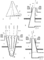
[0056]
図4には本発明の一実施例のバーナの構造例を示す。図4(a)はバーナの中心軸を通り、出口部の長径部の最長径を通る平面に平行な方向の断面矢視図(図4(b)のB−B線断面の矢視図)を示し、図4(b)に図4(a)のA−A線断面の矢視図を示し、図4(c)はバーナの出口部を火炉(4)側から見た正面図を示す。
[0057]
図4に示すバーナは、バーナの燃料含有流体(11)の噴出流に直交する方向の断面形状を楕円状にしたものであり、その他の構成は図3に示すバーナと同じである。
[0058]
バーナの鉛直方向(燃料含有流体(11)の噴出流に直交する方向)の断面形状として、図3では矩形状、図4では楕円状の代表的な形状を示したが、矩形の短辺が円弧状のものや、幅広の菱形状などの類似な形状を採用しても、上述と同様の効果が得られる。
[0059]
図5に本発明の一実施例のバーナの構造例を示す。図5(a)はバーナの中心軸を通り、出口部の長径部の最長径を通る平面に平行な方向の断面矢視図(図5(b)のB−B線断面の矢視図)を示し、図5(b)に図5(a)のA−A線断面の矢視図を示し、図5(c)はバーナの出口部を火炉(4)側から見た正面図を示す。
[0060]
図5に示すバーナは、燃料含有流体供給ノズル(12)が燃料含有流体接続部(10a)から出口部に向けて長径部の大きさが燃料含有流体(11)の流れ方向に沿って次第に拡大されるが、短径部の大きさは燃料含有流体(11)の流れ方向に沿って次第に縮小されるものであり、その他の構成は図3に示すバーナと同じである。
[0061]
図5に示すバーナ構造の特徴は、燃料含有流体接続部(10a)から燃料含有流体供給ノズル(12)の出口部に向けての燃料含有流体(11)の流速の増加を抑制でき、圧力損失の最小化及び燃料含有流体供給ノズル(12)内の構成部品の摩耗抑制が図れる。
[0062]
図6に本発明の一実施例のバーナの構造例を示す。図6(a)はバーナの中心軸を通り、出口部の長径部の最長径を通る平面に平行な方向の断面矢視図(図6(b)のB−B線断面の矢視図)を示し、図6(b)に図6(a)のA−A線断面の矢視図を示し、図6(c)はバーナの出口部を火炉(4)側から見た正面図を示す。
[0063]
図6に示すバーナは、燃料含有流体供給ノズル(12)内を流れる燃料含有流体(11)が噴出流れ方向に沿って燃料含有流体供給ノズル(12)の拡大する方向に均等に供給されるように燃料含有流体案内板(19)を配置したものであり、その他の構成は図5に示すバーナと同じである。本例では燃料含有流体案内板(19)は3枚設置されており、燃料含有流体供給ノズル(12)の広がりに応じて燃料含有流体(11)に一様に広がりを持たせるため、中央の案内板(19)は中心軸上に、これを挟む両側の案内板(19)は中心軸を通る鉛直断面に対して角度α、βを持って配置されている。
[0064]
燃料含有流体案内板(19)により燃料含有流体供給ノズル(12)内を流れる燃料含有流体(11)の流れが複数に分割されるので、燃料含有流体接続部(10a)から燃料含有流体供給ノズル(12)の出口部に向けての燃料含有流体供給ノズル(12)の広がりに応じて燃料含有流体(11)が一様に広げられ、アンバランスなく燃焼させることができる。また、燃料含有流体(11)が一様に広げられることにより、流速の局所的な増加の抑制、圧力損失の最小化及び構成部品の摩耗抑制効果が図5に示す構成より、一層良くなる。
[0065]
図7に本発明の一実施例のバーナの構造例を示す。図7(a)はバーナの中心軸を通り、出口部の長径部の最長径を通る平面に平行な方向の断面矢視図を示し、図7(b)に図7(a)のB−B線断面の矢視図を、図7(c)に図7(a)のA−A線断面の矢視図を示す。
[0066]
図7に示すバーナは、図6に示すバーナと同様に燃料含有流体供給ノズル(12)内を流れる燃料含有流体(11)が、流れ方向に沿って燃料含有流体供給ノズル(12)の拡大する方向に均等に供給されるように燃料含有流体案内板(19)を配置し、燃料含有流体供給ノズル(12)の中心軸を通り、火炉(4)に向けて延長した線上の出口部の長径部の最長径を通る平面に対して、図7(a)のA−A線断面においては流体(11)の流れを下向きに変える燃料含有流体向き変更用案内板(21a)を、図7(a)のB−B線断面においては流体(11)の流れを上向きに変える燃料含有流体向き変更用案内板(21b)をバーナ出口部に設置している。燃料含有流体供給ノズル(12)と燃料含有流体案内板(19)とで形成された4つの燃料含有流体噴出流20(20a、20b)は、上記燃料含有流体向き変更用案内板(21a、21b)によって、下斜め向きの燃料含有流体噴出流(20a)と、上斜め向きの燃料含有流体噴出流(20b)が形成される。図7に示すバーナ構成により、燃料含有流体噴出流(20)の火炉(4)内での分散が促進され、火炉(4)後流部での燃焼が促進される効果を有する。
[0067]
図8に本発明の一実施例のバーナの構造例を示す。図8(a)はバーナの中心軸を通り、出口部の長径部の最長径を通る平面に平行な方向の断面矢視図を示し、図8(b)に図8(a)のB−B線断面の矢視図を、図8(c)に図8(a)のA−A線断面の矢視図を示す。
[0068]
図8に示すバーナは、図7に示すバーナと同様に燃料含有流体供給ノズル(12)内を流れる燃料含有流体(11)が、流れ方向に沿って燃料含有流体供給ノズル(12)の拡大する方向に均等に供給されるように燃料含有流体案内板(19)を配置し、燃料含有流体供給ノズル(12)の中心軸を通り、火炉(4)に向けて延長した線上の出口部の長径部の最長径を通る平面に対して、A−A線断面においては流体11の流れの向きを整流して直進させる燃料含有流体向き変更用案内板(21a)を設置し、B−B線断面においては流体(11)の流れを上向きに変える燃料含有流体向き変更用案内板(21b)を設置している。燃料含有流体供給ノズル(12)と燃料含有流体案内板(19)とで形成された4つの燃料含有流体噴出流(20a、20b)は、上記燃料含有流体向き変更用案内板(21a、21b)の設置によって、燃料含有流体噴出流(20a)は直進方向、燃料含有流体噴出流(20b)は上向きの噴流となる。
[0069]
整流して直進させる燃料含有流体向き変更用案内板(21a)を設置せず、向きを変える上記案内板(21b)のみを設置した場合も同様の燃料含有流体噴出流(20a、20b)が形成される。
[0070]
図8に示すバーナ構成により、例えば、火炉(4)の側壁側の水壁寄りの燃料含有流体噴出流を直進流とし、火炉(4)の側壁側の水壁寄りでない燃料含有流体噴出流を火炉中心側に対して斜め向きの流れとすることで、燃料含有流体噴出流(20)の火炉(4)内での分散を促進して火炉(4)後流部での燃焼が促進される効果を維持し、且つ火炉(4)側壁近傍への火炎流入を抑えて灰付着を防止する効果がある。
【0071】
図9に本発明の一実施例のバーナの構造例を示す。図9(a)はバーナの中心軸を通り、出口部の長径部の最長径に平行な方向の断面矢視図を示し、図9(b)にバーナの斜視図を示し、図9(c)に図9(a)のB−B線断面の矢視図を示し、図9(d)に図9(a)のA−A線断面の矢視図を示す。
【0072】
図9に示すバーナは、図7に示すバーナと同様に燃料含有流体供給ノズル(12)内を流れる燃料含有流体(11)が流れ方向に沿って燃料含有流体供給ノズル(12)の拡大する方向に均等に供給されるように燃料含有流体案内板(19)を配置している。燃料含有流体供給ノズル(12)の入り口部正面の形状は平行四辺形であり、燃料含有流体供給ノズル(12)の片方の側面(12a)は流れ方向に沿って斜め下に向かって、他方の側面(12b)は流れ方向に沿って斜め上に向かって配置され、燃料含有流体供給ノズル(12)出口に至っている。
【0073】
本構成により、燃料含有流体供給ノズル(12)の側面(12a)に近い部分では図9(d)に示すように斜め下向きの燃料含有流体噴出流(20a)を形成し、側面(12b)に近い部分では図9(c)に示すように斜め上向きの燃料含有流体噴出流(20d)を形成する。燃料含有流体供給ノズル(12)が燃料含有流体案内板(19)で仕切られた中央2つの流路からは、燃料含有流体噴出流(20a)と中心線の中間に噴出方向を有する燃料含有流体噴出流(20b)と、燃料含有流体噴出流(20d)と中心線の中間に噴出方向を有する燃料含有流体噴出流(20c)を形成する。
[0074]
図9のバーナ構成の効果は図7に示すバーナと同等であるが、燃料含有流体(11)の噴出方向を変化させるのに燃料含有流体向き変更用案内板(21)を用いていないので、当該案内板(21)で懸念される磨耗の問題が発生しない。
[0075]
図10には本発明の一実施例のバーナの構造例を示す。図10(a)はバーナの中心軸を通り、出口部の長径部の最長径を通る平面に平行な方向の断面矢視図(図10(b)のB−B線断面の矢視図)を示し、図10(b)に図10(a)のA−A線断面の矢視図を示し、図10(c)はバーナの出口部を火炉(4)側から見た正面図を示す。
[0076]
燃料含有流体ノズル(12)の出口部に燃料含有流体(11)の流れに直交して部分的に流れを遮蔽する燃料含有流体分割板(22)が設置されている。燃料含有流体分割板(22)によって燃料含有流体噴出流(20)は図11に示すように4つに分割される。分割によって、燃料含有流体噴出流(20)の表面積が拡大して火炉(4)内の輻射受熱が増大するとともに、燃料含有流体分割板(22)の後流側に負圧領域(22a)が形成されて図中矢印で示しているように周囲の高温ガスが負圧領域に流れ込む。輻射受熱の増加と負圧領域への高温ガスの流入は、ともに燃料への早期着火に寄与し、バーナ近傍の還元領域での燃焼が促進されて、燃焼ガスのNOx濃度の低減と燃焼効率向上に有効に作用する。
[0077]
図12には本発明の一実施例のバーナの構造例を示す。図12(a)はバーナの中心軸を通り、出口部の長径部の最長径を通る平面に平行な方向の断面矢視図(図12(b)のB−B線断面の矢視図)を示し、図12(b)に図12(a)のA−A線断面の矢視図を示し、図12(c)はバーナの出口部を火炉(4)側から見た正面図を示す。
[0078]
燃料含有流体ノズル(12)の出口部であって燃料含有流体案内板(19)の出口部に燃料含有流体(11)の流れに直交して部分的に流れを遮蔽する燃料含有流体分割板(22)が設置されている。燃料含有流体案内板(19)によって、燃料含有流体供給ノズル(12)内で燃料含有流体(11)が均等に供給されるので、より効果的にNOxの低減と燃焼効率の向上が実現する。
[0079]
図13には本発明の一実施例のバーナの構造例を示す。図13(a)はバーナの中心軸を通り、出口部の長径部の最長径を通る平面に平行な方向の断面矢視図(図13(b)のB−B線断面の矢視図)を示し、図13(b)に図13(a)のA−A線断面の矢視図を示し、図13(c)はバーナの出口部を火炉(4)側から見た正面図を示す。
[0080]
燃料含有流体ノズル(12)の出口部に断面L字型の保炎器(17)が設置されている。保炎器(17)の後流には循環渦(図示せず)が形成されて高温の燃焼ガスを保炎器(17)の近傍に引き戻すため、燃料への早期着火に寄与し、バーナ近傍の還元領域での燃焼が促進されて、燃焼ガスのNOx濃度の低減と燃焼効率向上に有効に作用する。
[0081]
図14には本発明の一実施例のバーナの構造例を示す。図14(a)はバーナの中心軸を通り、出口部の長径部の最長径を通る平面に平行な方向の断面矢視図(図14(b)のB−B線断面の矢視図)を示し、図14(b)に図14(a)のA−A線断面の矢視図を示し、図14(c)はバーナの出口部を火炉(4)側から見た正面図を示す。
[0082]
図14に示す断面L字型の保炎器(17)の先端に二次空気の噴出方向を外側に広げる二次空気案内板(17a)が設置されている。案内板(17a)によって二次空気が外側に広がることにより保炎器(17)の後流の循環渦(図示せず)が大きくなり、高温の燃焼ガスの再循環量が増加し、燃料への着火をさらに早めて、バーナ近傍の還元領域での燃焼が促進され、燃焼ガスのNOx濃度の低減と燃焼効率向上に有効に作用する。
[0083]
図15には本発明の一実施例のバーナの構造例を示す。図15(a)はバーナの中心軸を通り、出口部の長径部の最長径を通る平面に平行な方向の断面矢視図(図15(b)のB−B線断面の矢視図)を示し、図15(b)に図15(a)のA−A線断面の矢視図を示し、図15(c)はバーナの出口部を火炉(4)側から見た正面図を示す。
[0084]
図15に示すバーナでは、二次空気用スリーブ(15)の先端に三次空気の噴出方向を外側に広げる三次空気案内板(15a)が設置されている。三次空気が外側に広がることにより火炎中心部の還元領域が拡大され、NOx濃度の低減と燃焼効率向上に有効に作用する。
[0085]
図16には本発明の一実施例のバーナの構造例を示す。図16(a)はバーナの中心軸を通り、出口部の長径部の最長径を通る平面に平行な方向の断面矢視図(図16(b)のB−B線断面の矢視図)を示し、図16(b)に図16(a)のA−A線断面の矢視図を示し、図16(c)はバーナの出口部を火炉(4)側から見た正面図を示す。
[0086]
図16に示すバーナは、燃料含有流体供給ノズル(12)の内部に上流側から断面積が次第に広がる三角柱状で下流側では断面積が次第に狭まる逆向きの三角柱状を組み合わせた燃料含有流体濃縮器(23)が設置されている。燃料含有流体濃縮器(23)により保炎器(17)近傍の燃料が濃縮され、燃料への早期着火に寄与して、バーナ近傍の還元領域での燃焼が促進され、燃焼ガスのNOx濃度の低減と燃焼効率向上に有効に作用する。
[0087]
図17には本発明の一実施例のバーナの構造例を示す。図17(a)はバーナの中心軸を通り、出口部の長径部の最長径を通る平面に平行な方向の断面矢視図(図17(b)のB−B線断面の矢視図)を示し、図17(b)に図17(a)のA−A線断面の矢視図を示し、図17(c)はバーナの出口部を火炉(4)側から見た正面図を示す。
[0088]
燃料含有流体供給ノズル(12)の内部に上流側は断面が次第に広がる三角柱状で、中間に四角柱状、下流側は断面積が次第に狭まる逆向きの三角柱状を組み合わせた燃料含有流体濃縮器(23’)が設置されている。本構成では、濃縮器(23’)周りの角度変化を小さくすることで剥離が抑えられ、燃料の濃縮効果が増進されて、NOx低減効果が高まると共に燃焼効率が向上する。
[0089]
図16、図17には濃縮器(23、23’)の効果的な構成例を示しているが、例えば三角柱など類似の構造を有する濃縮器を用いても、同様の効果が得られる。
[0090]
図18には本発明の一実施例のバーナの構造例を示す。図18(a)は、ノズル(12)の出口部の長辺を通って形成される燃料含有流体供給ノズル(12)面に平行な断面矢視図(図18(b)のB−B線断面)を示し、図18(b)に図18(a)のA−A線断面の矢視図を示し、図18(c)はバーナの出口部を火炉(4)側から見た正面図を示す。
[0091]
図18には燃料含有流体供給ノズル(12)の入口部に堰(せき)状の流体分配板(24)が設けられている。燃料含有流体(11)は堰(せき)状の流体分配板(24)の上流側に一旦衝突して、燃料含有流体供給ノズル(12)の長辺方向に均等に分散された後、燃料含有流体供給ノズル(12)内の燃料含有流体案内板(19)で仕切られた4つの流路に均等に導かれ、均等な状態を維持して火炉(4)に供給される。
[0092]
図19は燃料含有流体供給ノズル(12)の中心部に油供給ノズル(41)を設置した例を示す。図19(a)はバーナの中心軸を通り、出口部の長径部の最長径を通る平面に平行な方向の断面矢視図(図19(b)のB−B線断面の矢視図)を示し、図19(b)に図19(a)のA−A線断面の矢視図を示し、図19(c)はバーナの出口部を火炉(4)側から見た正面図を示す。
[0093]
図20は保炎器(17)の周囲にガス導入管(42)から水平管(43)を経由してガス供給ノズル(44)に繋がるガス噴出部を設置した例を示す。
[0094]
図20(a)はバーナの中心軸を通り、出口部の長径部の最長径を通る平面に平行な方向の断面矢視図(図20(b)のB−B線断面の矢視図)を示し、図20(b)に図20(a)のA−A線断面の矢視図を示し、図20(c)はバーナの出口部を火炉(4)側から見た正面図を示す。
[0095]
図21に示すバーナ構造は該バーナの燃料含有流体供給ノズル(12)内を流れる燃料含有流体(11)の流れに直交する断面形状が矩形である燃料含有流体供給ノズル(12)の長辺側を上下方向に向けて配置した場合の火炉(4)側から見た燃料含有流体供給ノズル(12)の正面図(図21(a))と平面図(図21(b))を示す。
[0096]
火炉(4)正面側から見て図21に示す燃料含有流体供給ノズル(12)からは、該ノズル(12)の長辺側の上方向と下方向で火炉壁面に直交する平面に対して左右互いに水平方向の反対側に傾斜して燃料含有流体噴出流(20a、20b)が形成される。本燃料含有流体噴出流の形成は図7又は図9のバーナ構造を適用することで達成される。
[0097]
図22に示すバーナ構造は該バーナの燃料含有流体供給ノズル(12)内を流れる燃料含有流体(11)の流れに直交する断面形状が矩形である燃料含有流体供給ノズル(12)の長辺側を上下方向に向けて配置した場合の火炉(4)側から見た燃料含有流体供給ノズル(12)の正面図(図22(a))と平面図(図22(b))を示す。
[0098]
火炉(4)正面側から見て図22に示す燃料含有流体供給ノズル(12)からは、該ノズル(12)の長辺側の上方向と下方向で火炉壁面に直交する平面に対して片方は水平方向に傾斜して燃料含有流体噴出流(20b)を形成し、他方は火炉壁面に直交して燃料含有流体噴出流(20c)を形成する。本燃料含有流体噴出流の形成は図8のバーナ構造を適用することで達成される。
【0099】
図23には、図21に示す燃料含有流体供給ノズル(12)が一つの火炉壁面に上下方向に3段と水平方向に4列に多数配置された例を示す。一つの火炉壁の右半分には図21に示す燃料含有流体供給ノズル(12)と同じ向きに噴出流(20a、20b)を形成するノズル(12)を配置し、火炉壁の左半分には図21に示す燃料含有流体供給ノズル(12)と鏡面対象位置に噴出流(20a、20b)を形成するノズル(12)を配置している。燃料含有流体噴出流(20a、20b)の向きを一つの火炉壁面で左右対称的に配置することにより、火炉(4)内の流動及び燃焼状態の左右バランスを良好に維持できる特徴がある。
なお、一つの火炉壁の左右半分に分けて配置される燃料含有流体供給ノズル(12)からの噴出流(20a、20b)が鏡面対象位置に形成される構成であれば、ノズル(12)からの燃料含有流体噴出流(20a、20b)の向きが図示の通りである必要はない。
【0100】
図24には、燃料含有流体供給ノズル(12)が一つの火炉壁面に上下方向に3段と水平方向に4列配置されているが、左右の両端列には図22に示す燃料含有流体供給ノズル(12)が鏡面対象に配置され、中央2列には図21に示す燃料含有流体供給ノズル(12)が鏡面対象に配置された例を示す。火炉(4)側壁の水壁寄りには直進する燃料含有流体噴出流(20c)と傾斜した燃料含有流体噴出流(20b)を持つバーナを配列し、中央寄りには両側に傾斜した燃料含有流体噴出流(20a、20b)を配列することにより、燃料含有流体噴出流(20a、20b)の火炉(4)内での分散を促進して火炉(4)後流部での燃焼が促進される効果を維持し、且つ火炉(4)側壁近傍への火炎流入を抑えて灰付着を防止する効果がある。
【0101】
図25には一つの火炉壁の全バーナの燃料含有流体ノズル(12)として全て同じ図21に示す燃料含有流体噴出流(20a、20b)を形成する燃料含有流体供給ノズル(12)を配置している例を示している。本実施例は、特に容積の小さな火炉(4)において、燃料含有流体噴出流(20a、20b)の衝突を避けることで、燃料の局所的集中を抑えて、燃焼ガス中のNOx濃度の低減及び燃焼効率向上に有効な配置である。
【0102】
上記図21〜図25のバーナ構造は火炉の寸法やバーナ配置などの条件に応じて適正に選択することにより、最適な燃焼特性を実現することが出来る。
【0103】
図26には本発明の一実施例のバーナを配置したボイラの火炉壁の平面図を示す。図26には火炉壁にスパイラル状の水壁管(25)を有するボイラにおいて、水平に対して斜めの水壁管25のアレンジに沿って矩形状の開口部(26)が設置されており、本発明の前記各実施例で説明した各種のバーナが取り付けられる。スパイラル状の水壁管(25)に沿って開口部(26)を設けることにより、該開口部(26)を形成するために必要な水壁管(25)の員数を最小限にすることが可能となり、経済性が向上する。
【0104】
前述のように、本発明の各実施例からなる燃焼装置は、燃料含有流体噴出流(20)が火炉(4)内で広がるため、燃焼空間を有効に活用できる特徴を有するが、図26の構成とすることにより、火炉(4)の水平(幅)方向に燃料含有流体噴出流(20a、20b)が広がるため、火炉水平(幅)方向で燃料含有流体(11)の分布が均一化され、実質の炉内滞留時間がさらに長くなり、燃焼ガス中のNOx濃度の低減と燃焼効率向上に有効に作用する。
【0105】
図27に本発明の一実施例のバーナを配置したボイラの火炉壁の平面図を示す。図27には火炉壁に鉛直方向に伸びる水壁管(25)を有するボイラにおいて、水壁管(25)のアレンジに沿って矩形状の開口部(26)が設置されており、本発明からなる前記各実施例のバーナが取り付けられる。水壁管(25)に沿って開口部(26)を設けることにより、開口部(26)を形成するために必要な水壁管(25)の員数を最小限にすることが可能となり、経済性が向上する。
【0106】
本構成において、火炉水平(幅)方向にも混合流体の分散を促進するために、図7〜図9に示すバーナで燃料含有流体噴出流(20a、20b)の方向が互いに違う方向を向くような構成にすることで、火炉(4)内の全体の燃料含有流体(11)の分散が促進され、NOx低減と燃焼効率向上に有効に作用する。
【0107】
一般的にバーナでは補助燃料として油やガスが用いられるが、本発明の実施例のバーナの一部にこれら燃料の供給ノズルを設置しても、本発明の実施例のバーナの特徴や効果は維持される。
【産業上の利用可能性】
【0108】
バーナ大容量化の傾向にもコスト低減を図りながら燃焼性能を低下させないで対応可能なバーナ構造として将来産業上の利用可能性が高い。
【図面の簡単な説明】
[0109]
[図1]本発明と従来技術のバーナ出口の着火領域の説明図である。
[図2]本発明と従来技術のバーナ出口の未着荷領域の説明図である。
[図3]本発明の一実施例のバーナの構造例を示す(図3(a)はバーナの中心軸を通り、出口部の長径部の最長径を通る平面に平行な方向の断面図を示し、図3(b)に図3(a)のA−A線断面の矢視図を示し、図3(c)はバーナの出口部を火炉側から見た正面図を示す。)。
[図4]発明の一実施例のバーナの構造例を示す(図4(a)はバーナの中心軸を通り、出口部の長径部の最長径を通る平面に平行な方向の断面図を示し、図4(b)に図4(a)のA−A線断面の矢視図を示し、図4(c)はバーナの出口部を火炉側から見た正面図を示す。)。
[図5]本発明の一実施例のバーナの構造例を示す(図5(a)はバーナの中心軸を通り、出口部の長径部の最長径を通る平面に平行な方向の断面矢視図を示し、図5(b)に図5(a)のA−A線断面の矢視図を示し、図5(c)はバーナの出口部を火炉側から見た正面図を示す。)。
[図6]本発明の一実施例のバーナの構造例を示す(図6(a)はバーナの中心軸を通り、出口部の長径部の最長径を通る平面に平行な方向の断面矢視図を示し、図6(b)に図6(a)のA−A線断面の矢視図を示し、図6(c)はバーナの出口部を火炉側から見た正面図を示す。)。
[図7]本発明の一実施例のバーナの構造例を示す(図7(a)はバーナの中心軸を通り、出口部の長径部の最長径を通る平面に平行な方向の断面矢視図を示し、図7(b)に図7(a)のB−B線断面の矢視図を示し、図7(c)に図7(a)のA−A線断面の矢視図を示す。)。
[図8]本発明の一実施例のバーナの構造例を示す(図8(a)はバーナの中心軸を通り、出口部の長径部の最長径を通る平面に平行な方向の断面矢視図を示し、図8(b)に図8(a)のB−B線断面の矢視図を示し、図8(c)に図8(a)のA−A線断面の矢視図を示す。)。
[図9]本発明の一実施例のバーナの構造例を示す(図9(a)はバーナの中心軸を通り、出口部の長径部の最長径を通る平面に平行な方向の断面矢視図を示し、図9(b)にバーナの斜視図を示し、図9(c)に図9(a)のB−B線断面の矢視図を示し、図9(d)に図9(a)のA−A線断面の矢視図を示す。)。
[図10]本発明の一実施例のバーナの構造例を示す(図10(a)はバーナの中心軸を通り、火炉に向けて延長した線上の出口部の長径部の最長径を通る平面に平行な方向の断面矢視図を示し、図10(b)に図10(a)のA−A線断面の矢視図を示し、図10(c)にバーナの出口部を火炉側から見た正面図示す。)。
[図11]図10に記載の発明による効果の説明図を示す。
[図12]図10に示す発明の一実施例のバーナの構造例を示す(図12(a)はバーナの中心軸を通り、火炉に向けて延長した線上の出口部の長径部の最長径を通る平面に平行な方向の断面矢視図を示し、図12(b)に図12(a)のA−A線断面の矢視図を示し、図12(c)にバーナの出口部を火炉側から見た正面図示す。)。
[図13]本発明の一実施例のバーナの構造例を示す(図13(a)はバーナの中心軸を通り、出口部の長径部の最長径を通る平面に平行な方向の断面矢視図を示し、図13(b)に図13(a)のA−A線断面の矢視図を示し、図13(c)はバーナの出口部を火炉側から見た正面図を示す。)。
[図14]本発明の一実施例のバーナの構造例を示す(図14(a)はバーナの中心軸を通り、出口部の長径部の最長径を通る平面に平行な方向の断面矢視図を示し、図14(b)に図14(a)のA−A線断面の矢視図を示し、図14(c)はバーナの出口部を火炉側から見た正面図を示す。)。
[図15]本発明の一実施例のバーナの構造例を示す(図15(a)はバーナの中心軸を通り、出口部の長径部の最長径を通る平面に平行な方向の断面矢視図を示し、図15(b)に図15(a)のA−A線断面の矢視図を示し、図15(c)はバーナの出口部を火炉側から見た正面図を示す。)。
[図16]本発明の一実施例のバーナの構造例を示す(図16(a)はバーナの中心軸を通り、出口部の長径部の最長径を通る平面に平行な方向の断面矢視図を示し、図16(b)に図16(a)のA−A線断面の矢視図を示し、図16(c)はバーナの出口部を火炉側から見た正面図を示す。)。
[図17]本発明の一実施例のバーナの構造例を示す(図17(a)はバーナの中心軸を通り、出口部の長径部の最長径を通る平面に平行な方向の断面矢視図を示し、図17(b)に図17(a)のA−A線断面の矢視図を示し、図17(c)はバーナの出口部を火炉(4)側から見た正面図を示す。)。
[図18]本発明の一実施例のバーナの構造例を示す(図18(a)は、出口部の長辺を通って形成される燃料含有流体供給ノズル面に平行な断面矢視図(図18(b)のB−B線断面)を示し、図18(b)に図18(a)のA−A線断面の矢視図を、図18(c)はバーナの出口部を火炉側から見た正面図を示す。)。
[図19]燃料含有流体供給ノズルの中心部に油供給ノズルを設置した例を示す。
[図20]保炎器の周囲にガス供給ノズルを設置した例を示す。
[図21]燃料含有流体供給ノズルの正面図(図21(a))と平面図(図21(b))を示す。
[図22]他の構成に対する燃料含有流体供給ノズルの正面図(図22(a))と平面図(図22(b))を示す。
[図23]図21に示す燃料含有流体供給ノズルの多数が一つの火炉壁面に上下方向に3段と水平方向に4列配置された例を示す。
[図24]図21及び図22に示す燃料含有流体供給ノズルの多数が一つの火炉壁面に上下方向に3段と水平方向に4列配置された例を示す。
[図25]図21に示す燃料含有流体供給ノズルの多数が一つの火炉壁面に上下方向に3段と水平方向に4列配置された他の実施例を示す。
[図26]本発明の一実施例のバーナを配置したボイラの火炉壁の平面図を示す。
[図27]本発明の一実施例のバーナを配置したボイラの火炉壁の平面図を示す。
[図28]従来技術からなる固体燃料用バーナの例を示す(図28(a)はバーナの側断面図、図28(b)は該バーナを火炉内から見た正面図である。)。
[図29]図29(a)に従来技術のバーナの燃料含有流体供給ノズルの燃料含有流体の噴出流に沿った方向の断面図を示し、図29(b)に燃料含有流体供給ノズルの出口部を火炉側から見た正面図を示す。
[図30]従来技術のバーナの燃料含有流体供給ノズルの燃料含有流体の噴出流に沿った断面方向の火炉内の火炎伝播の挙動を模式的に示す。
【符号の説明】
【0110】
3 風箱 4 火炉
10 燃料含有流体流路 10a 燃料含有流体接続部
11 燃料含有流体 12 燃料含有流体供給ノズル
13 二次空気 14 三次空気
15 燃焼用空気スリーブ 15a 三次空気案内板
16 バーナスロート 17 保炎器
17a 二次空気案内板 19 燃料含有流体案内板
20,20a,20b,20c,20d 燃料含有流体噴出流
21a,21b 燃料含有流体向き変更用案内板
22 燃料含有流体分割板 22a 負圧領域
23,23’ 濃縮器 24 流体分配板
25 水壁管 26 開口部
31 未着火領域 32 着火領域
33 着火位置 41 油供給ノズル
42 ガス導入管 43 水平管
44 ガス供給ノズル
L1 未着火距離
L2 着火位置から混合流体噴出流中心部までの距離【Technical field】
[0001]
The present invention relates to a burner, a combustion apparatus equipped with the burner, and a boiler, and more particularly to the burner capable of efficient low nitrogen oxide (NOx) combustion.
[Background]
[0002]
FIG. 28 shows an example of a conventional burner for solid fuel (pulverized coal, biomass fuel, etc.). FIG. 28A is a side sectional view of the burner, and FIG. 28B is a front view of the burner as seen from the furnace (4) side. The solid fuel burner includes a fuel-containing fluid supply nozzle (12) that defines a fuel-containing fluid flow path through which a fuel-containing fluid (11) containing solid fuel and primary air for conveyance flows toward the furnace (4); And a combustion air sleeve (15) provided on the outer periphery of the fuel-containing fluid supply nozzle (12), and the air in the wind box (3) is defined by the sleeve (15). And is supplied as secondary air (13) and tertiary air (14). A flame holder (17) is provided at the tip of the fuel-containing fluid supply nozzle (12), and the fuel can be ignited from the vicinity of the burner by the effect of the circulating vortex formed in the downstream flow.
[0003]
The tip of the combustion air sleeve (15) is at a position facing a burner throat (16) provided on the wall surface of the furnace. The tip of the sleeve (15) is a combustion air guide plate (15a) extending outside the burner. The tertiary air (14) is spread outward by the combustion air guide plate (15a), delays the mixing of the air into the flame center, and promotes combustion under reducing atmosphere conditions lacking air. The generation of nitrogen oxides (NOx) in the combustion gas is suppressed.
[0004]
FIG. 1 (c) shows a cross-sectional view of the fuel-containing fluid supply nozzle (12) in the conventional burner in the direction along the jet flow of the fuel-containing fluid (11), and FIG. As shown in the front view of the outlet of the fuel-containing fluid supply nozzle (12) of the burner from the furnace (4) side, in the prior art burner, the cross section of the outlet of the fuel-containing fluid supply nozzle (12) Has a shape close to a circle. When the fuel-containing fluid (11) is charged into the furnace (4), the fuel-containing fluid supply nozzle (12) is heated by the radiation in the furnace (4) or the circulation vortex behind the flame holder (17). The fuel is ignited in the vicinity of the exit.
[0005]
FIG. 29 (a) shows a cross-sectional view of the fuel-containing fluid supply nozzle (12) in the prior art burner in the direction along the jet flow of the fuel-containing fluid (11), and FIG. 29 (b) shows the fuel-containing fluid supply. As shown in a front view of the outlet portion of the nozzle (12) as viewed from the furnace (4) side, the ignition position of the fuel in the fuel-containing fluid ejected from the fuel-containing fluid supply nozzle (12) into the furnace (4) ( 33) is formed. After the fuel ignites on the surface of the jet of the fuel-containing fluid (11), the flame formed gradually propagates toward the center of the jet of the fuel-containing fluid (11). FIG. 30 schematically shows the behavior of flame propagation in the furnace (4) in the cross-sectional direction along the jet flow of the fuel-containing fluid (11) of the fuel-containing fluid supply nozzle (12) in the prior art burner. is there. An ignition region (32) is formed around the conical non-ignition region (31).
[0006]
The burner having a circular cross section shown in FIGS. 28 to 30 is often used in a so-called opposed combustion system, which is disposed on a pair of opposed furnace walls. On the other hand, in so-called tangential combustion, in which fuel is burned while jetting the fuel-containing fluid in the direction of swirling into the furnace (4) from the outlets of the plurality of fuel-containing fluid supply nozzles (12) along the furnace wall surface. The outlet shape of the cross section of the fuel-containing fluid supply nozzle (12) (cross section orthogonal to the fuel-containing fluid flow) is often a square or a rectangle close to a square.
[0007]
Also, a burner in which the outlet shape of the transverse section of the fuel-containing fluid supply nozzle (12) (cross section orthogonal to the fuel-containing fluid flow) is rectangular, elliptical or substantially elliptical having a major axis and a minor axis is as follows. It is disclosed in
[Patent Document 1]
JP-T 59-500981
[Patent Document 2]
JP-A-8-226615
[Patent Document 3]
Japanese Patent Laid-Open No. 11-281090
DISCLOSURE OF THE INVENTION
[Problems to be solved by the invention]
[0008]
Generally, the cross section of the outlet of the fuel-containing fluid supply nozzle (12) of the burner has a circular or nearly square shape, and ignited outside the fuel-containing fluid jet in the furnace (4) as shown in FIG. It may take a considerable distance for the flame to propagate to the center of the fuel-containing fluid jet. The distance at which the ignited flame in the direction of the jet flow of the fuel-containing fluid (11) from the fuel-containing fluid supply nozzle (12) propagates to the center of the fuel jet, that is, the unignited distance L1 ′ shown in FIG. The larger the diameter or the peripheral portion of the fluid supply nozzle (12), the longer and the non-ignition area (31) is enlarged. Promoting combustion in the reduction region in the vicinity of the burner is important for suppressing NOx generation in the combustion gas, but the expansion of the unignited region (31) hinders the characteristics of suppressing this NOx concentration. It will be. In addition, the expansion of the non-ignition region (31) means that the combustion time after ignition is shortened, which also causes a decrease in combustion efficiency.
[0009]
Increasing the burner capacity (reducing the number of burners) is an effective technique for reducing cost and improving operability. In the prior art, however, the diameter or outer diameter of the fuel-containing fluid supply nozzle (12) increases as the burner capacity increases. The length of the part becomes longer, the unignited region (31) expands, and there is a problem that causes an increase in NOx and a decrease in combustion efficiency. This problem was caused by the large distance from the ignition region (32) on the fuel-containing fluid jet surface to the center of the fuel-containing fluid jet. Further, the outlet shape of the transverse section (cross section perpendicular to the fuel-containing fluid flow) of the fuel-containing fluid supply nozzle (12) described in
[0010]
SUMMARY OF THE INVENTION An object of the present invention is to provide a solid fuel burner that prevents an increase in the unignited region while preventing the increase in the NOx concentration in the combustion gas and prevents a decrease in combustion efficiency while increasing the capacity, and a combustion apparatus equipped with the burner. And providing a boiler.
[Means for Solving the Problems]
[0011]
The problems of the present invention are solved by the following means.
The invention according to
[0012]
[0013]
[0014]
Claim 2 The described invention is the burner according to
[0015]
[0016]
[0017]
[0018]
Claim 6 In the described invention, the fuel-containing fluid direction changing guide plate (21) extends the central axis of the fuel-containing fluid supply nozzle (12) into the furnace (4) for a part of the fuel-containing fluid (11). And is arranged in parallel to a plane parallel to a plane passing through the longest diameter of the long diameter portion of the nozzle (12), and for the other fuel-containing fluid (11), the center of the fuel-containing fluid supply nozzle (12) The shaft is disposed so as to have an inclination angle with respect to a plane parallel to a plane passing through the longest diameter of the long diameter portion of the nozzle (12) through a line extending in the furnace (4). 4 It is a burner of description.
[0019]
Claim 7 In the described invention, the fuel-containing fluid supply nozzle (12) is partitioned into a plurality of flow paths by the fuel-containing fluid guide plate (19), and the center axis of each flow path is a fuel-containing fluid supply nozzle ( The central axis of 12) passes through a line extending into the furnace (4), and the furnace (4) is inclined at different inclination angles with respect to a plane parallel to a plane passing through the longest diameter of the long diameter portion of the nozzle (12) outlet. Claims provided on the wall 2 It is a burner of description.
[0020]
[0021]
[0022]
[0023]
[0024]
[0025]
[0026]
[0027]
[0028]
[0029]
[0030]
Claim 18 The described invention is a boiler having a furnace wall composed of a group of water wall pipes (25) extending in a vertical direction, and is rectangular, elliptical or substantially elliptical along the longitudinal direction of the water wall pipe (25). An opening (26) having a shape is provided in the furnace wall, ~ 14 It is a boiler which attaches the burner in any one of to the said opening part (26).
The invention's effect
[0031]
According to the first aspect of the present invention, even if the burner capacity is increased, it is possible to suppress the expansion of the unignited region, and the fuel-containing fluid can be maintained even after the fuel-containing fluid (11) is put into the furnace (4). (11) spreads in the width direction, and the cross-sectional area of the jet flow of the fuel-containing fluid (11) is enlarged and the flow velocity is reduced, so that it is effective for reducing the unignited distance compared to the prior art. Because the fuel-containing fluid (11) spreads in the furnace (4), the combustion space can be used effectively, and the residence time in the furnace becomes longer, and the effect of reducing NOx concentration in combustion gas and improving combustion efficiency There is. Further, since the size of the short diameter portion of the fuel-containing fluid supply nozzle (12) is unchanged, it is effective for simplifying the structure. In addition, since the upstream flow velocity of the fuel-containing fluid supply nozzle (12) can be increased, it is effective for preventing flashback in the case of fuel that is easily ignited.
[0032]
[0033]
[0034]
Since the flow of the fuel containing fluid (11) is divided into a plurality of parts by the containing fluid guide plate (19), the fuel containing fluid is directed from the fuel containing fluid connecting portion (10a) toward the outlet of the fuel containing fluid supply nozzle (12). (11) is supplied uniformly in the direction in which the nozzle (12) expands, and the effects of NOx reduction, combustion efficiency improvement, flow velocity increase suppression, pressure loss minimization, and component wear suppression effect are claimed. It becomes much better than the invention of the present invention.
[0035]
[0036]
[0037]
Claim 6 According to the described invention, the four fuel-containing fluid jets (20) formed by the fuel-containing fluid supply nozzle (12) and the fuel-containing fluid guide plate (19) are divided into two groups (20a, 20b). Thus, for example, the fuel-containing fluid jet flow (20a) near the furnace side wall is made a straight flow, and the fuel-containing fluid jet flow (20b) not near the furnace side wall is jetted with an inclination in the horizontal direction. While maintaining the promotion of combustion in the wake of the furnace, there is an effect of suppressing the inflow of flame to the vicinity of the furnace side wall and preventing ash adhesion.
[0038]
Claim 7 According to the described invention, the fuel-containing fluid (11) can be ejected from the fuel-containing fluid supply nozzle (12) into the furnace (4) with different inclination angles with respect to the horizontal direction or the vertical direction, Since the direction of the fuel-containing fluid jet flow (20) can be changed without using the components in the fuel-containing fluid supply nozzle (12) where solid fuel such as pulverized coal directly collides, it is effective for suppressing wear of the components. is there.
[0039]
[0040]
[0041]
[0042]
[0043]
[0044]
[0045]
[0046]
[0047]
[0048]
[0049]
Claim 18 According to the described invention, since the rectangular opening (26) is installed along the arrangement of the water wall pipe (25) in the vertical direction on the furnace wall, the longitudinal direction and the opening of the water wall pipe (25) are provided. The distance L2 from the ignition position (33) in the direction orthogonal to the processing of the water wall pipe (25) and the bent rectangular jet flow is obtained by arranging the longitudinal direction of the long diameter part of the part (26) in alignment. Along with the reduction compared to L2 ′, the unignited distance L1 is greatly reduced compared to the unignited distance L1 ′ of the prior art.
[0050]
Embodiments of the present invention will be described with reference to the drawings.
The basic concept of the present invention will be described with reference to FIGS. FIG. 1 shows the ignition position (33) in the
[0051]
As shown in FIG. 1 (d), in the prior art, a ring-shaped ignition position (33) exists around the circular jet flow of the fuel-containing fluid (11) ejected from the fuel-containing fluid supply nozzle (12) of the burner. To do. On the other hand, in this embodiment, as shown in FIG. 1B, an ignition position (33) is formed around the rectangular jet flow of the fuel-containing fluid (11) ejected from the fuel-containing fluid supply nozzle (12) of the burner. ) Exists.
[0052]
In the present embodiment, the shape of the outlet of the fuel-containing fluid supply nozzle (12) of the burner is rectangular and the length of the short side is reduced, so that the fuel-containing fluid (11) in the furnace (4) The distance L2 (FIG. 1 (b)) from the ignition position (33) in the direction orthogonal to the rectangular cross-sectional jet flow of the fuel-containing fluid (11) to the jet flow center is the same as that of the conventional fuel-containing fluid (11). Compared to the distance L2 ′ (FIG. 1 (d)) from the ignition position (33) in the direction perpendicular to the cross-sectional circular jet flow of the fuel-containing fluid (11) to the jet flow center.
[0053]
FIG. 2 shows the distance at which the flame propagates from the ignition position (33) in the jet flow direction of the fuel-containing fluid (11) from the fuel-containing fluid supply nozzle (12) in this embodiment to the center of the fuel jet (unignition distance). FIG. 3 is a cross-sectional view of a burner fuel-containing fluid supply nozzle (12) showing that L1 (FIG. 2 (a)) is reduced as compared to the unignited distance L1 ′ (FIG. 2 (b)) of the prior art. In this embodiment, the distance L2 from the ignition position (33) in the direction perpendicular to the rectangular jet flow of the fuel-containing fluid (11) to the center of the jet flow of the fuel-containing fluid (11) is the distance L2 ′ of the prior art. As the comparison is reduced, the non-ignition distance L1 is greatly reduced as compared with the conventional non-ignition distance L1 ′.
[0054]
FIG. 3 shows a structural example of a burner according to an embodiment of the present invention. FIG. 3A is a cross-sectional view taken in the direction parallel to a plane passing through the central axis of the burner and passing through the longest diameter of the long diameter portion of the outlet (an arrow view taken along the line BB in FIG. 3B). 3 (b) shows a cross-sectional view taken along the line AA in FIG. 3 (a), and FIG. 3 (c) shows a front view of the outlet portion of the burner as viewed from the furnace (4) side. .
[0055]
The cylindrical fuel-containing fluid flow path (10) is connected to a fuel-containing fluid supply nozzle (12) having a rectangular cross section via a circular cross-section connection portion (10a), and the fuel-containing fluid supply nozzle (12) is connected to the furnace (4). ) Has a structure sufficient to form a jet flow having a rectangular cross section. Even after the fuel-containing fluid (11) is put into the furnace (4), the fuel-containing fluid (11) spreads along the jet flow direction, and the cross-sectional area of the jet flow of the fuel-containing fluid (11) is enlarged to increase the flow velocity. Therefore, it effectively acts to further reduce the unignited distance L1 shown in FIG. In addition, since the fuel-containing fluid (11) spreads in the furnace (4), the combustion space can be used effectively, the residence time in the furnace becomes longer, and the NOx concentration in the combustion gas is reduced and the combustion efficiency is improved. It works effectively. Around the fuel-containing fluid supply nozzle (12), a combustion air sleeve (15) having a rectangular cross section and a burner throat (16) having a rectangular cross section are arranged.
[0056]
FIG. 4 shows an example of the structure of a burner according to an embodiment of the present invention. 4A is a cross-sectional arrow view in a direction parallel to a plane passing through the central axis of the burner and passing through the longest diameter of the long diameter portion of the outlet portion (an arrow view of the cross section along line BB in FIG. 4B). 4 (b) shows an arrow view of the cross section along line AA in FIG. 4 (a), and FIG. 4 (c) shows a front view of the outlet portion of the burner as seen from the furnace (4) side. .
[0057]
The burner shown in FIG. 4 has an elliptical cross-sectional shape in a direction perpendicular to the jet flow of the fuel-containing fluid (11) of the burner, and the other configuration is the same as that of the burner shown in FIG.
[0058]
As a cross-sectional shape in the vertical direction of the burner (direction perpendicular to the jet flow of the fuel-containing fluid (11)), a rectangular shape is shown in FIG. 3 and an elliptical shape is shown in FIG. Even if a similar shape such as an arc shape or a wide diamond shape is employed, the same effect as described above can be obtained.
[0059]
FIG. 5 shows an example of the structure of a burner according to an embodiment of the present invention. FIG. 5A is a cross-sectional arrow view in a direction parallel to a plane passing through the central axis of the burner and passing through the longest diameter portion of the outlet portion (an arrow view of the cross section along line BB in FIG. 5B). 5 (b) shows a cross-sectional view taken along the line AA in FIG. 5 (a), and FIG. 5 (c) shows a front view of the outlet portion of the burner as viewed from the furnace (4) side. .
[0060]
In the burner shown in FIG. 5, the fuel-containing fluid supply nozzle (12) gradually increases in size along the flow direction of the fuel-containing fluid (11) from the fuel-containing fluid connection portion (10a) toward the outlet. However, the size of the minor axis portion is gradually reduced along the flow direction of the fuel-containing fluid (11), and other configurations are the same as those of the burner shown in FIG.
[0061]
The feature of the burner structure shown in FIG. 5 is that the increase in the flow rate of the fuel-containing fluid (11) from the fuel-containing fluid connection portion (10a) toward the outlet portion of the fuel-containing fluid supply nozzle (12) can be suppressed, and the pressure loss And the wear of the components in the fuel-containing fluid supply nozzle (12) can be suppressed.
[0062]
FIG. 6 shows an example of the structure of a burner according to an embodiment of the present invention. FIG. 6A is a cross-sectional arrow view in a direction parallel to the plane passing through the central axis of the burner and passing through the longest diameter of the long diameter portion of the outlet portion (an arrow view of the cross section along line BB in FIG. 6B). 6 (b) shows an arrow view of the cross section along line AA in FIG. 6 (a), and FIG. 6 (c) shows a front view of the outlet portion of the burner viewed from the furnace (4) side. .
[0063]
In the burner shown in FIG. 6, the fuel-containing fluid (11) flowing in the fuel-containing fluid supply nozzle (12) is supplied uniformly in the direction in which the fuel-containing fluid supply nozzle (12) expands along the jet flow direction. The fuel-containing fluid guide plate (19) is disposed on the other, and the other configuration is the same as that of the burner shown in FIG. In this example, three fuel-containing fluid guide plates (19) are installed, and the fuel-containing fluid (11) is uniformly spread according to the spread of the fuel-containing fluid supply nozzle (12). The guide plates (19) are arranged on the central axis, and the guide plates (19) on both sides sandwiching the guide plate (19) are arranged at angles α and β with respect to a vertical section passing through the central axis.
[0064]
Since the flow of the fuel-containing fluid (11) flowing through the fuel-containing fluid supply nozzle (12) is divided into a plurality of parts by the fuel-containing fluid guide plate (19), the fuel-containing fluid supply nozzle from the fuel-containing fluid connection (10a) The fuel-containing fluid (11) is uniformly spread according to the spread of the fuel-containing fluid supply nozzle (12) toward the outlet of (12), and can be burned without imbalance. Further, by uniformly spreading the fuel-containing fluid (11), the effects of suppressing the local increase in the flow velocity, minimizing the pressure loss, and suppressing the wear of the components are further improved than the structure shown in FIG.
[0065]
FIG. 7 shows an example of the structure of a burner according to an embodiment of the present invention. FIG. 7 (a) shows a cross-sectional arrow view in a direction parallel to a plane passing through the central axis of the burner and passing through the longest diameter of the long diameter portion of the outlet portion, and FIG. An arrow view of the B line cross section is shown in FIG. 7C, and an arrow view of the AA line cross section of FIG. 7A is shown.
[0066]
In the burner shown in FIG. 7, the fuel-containing fluid (11) flowing in the fuel-containing fluid supply nozzle (12) is expanded along the flow direction in the same manner as the burner shown in FIG. The fuel-containing fluid guide plate (19) is arranged so as to be evenly supplied in the direction, passes through the central axis of the fuel-containing fluid supply nozzle (12), and extends to the furnace (4). The guide plate (21a) for changing the direction of the fuel-containing fluid that changes the flow of the fluid (11) downward in the cross-section taken along the line AA of FIG. In the cross section along line B-B in a), a fuel-containing fluid direction changing guide plate (21b) that changes the flow of the fluid (11) upward is installed at the burner outlet. The four fuel-containing fluid jets 20 (20a, 20b) formed by the fuel-containing fluid supply nozzle (12) and the fuel-containing fluid guide plate (19) are connected to the fuel-containing fluid direction changing guide plates (21a, 21b). ), A fuel-containing fluid jet flow (20a) in a downward slant direction and a fuel-containing fluid jet flow (20b) in a slant direction are formed. The burner configuration shown in FIG. 7 has an effect of promoting the dispersion of the fuel-containing fluid jet stream (20) in the furnace (4) and promoting the combustion in the downstream part of the furnace (4).
[0067]
FIG. 8 shows an example of the structure of a burner according to an embodiment of the present invention. FIG. 8A shows a cross-sectional view in a direction parallel to a plane passing through the central axis of the burner and passing through the longest diameter of the long diameter portion of the outlet portion, and FIG. An arrow view of the B line section is shown in FIG. 8C, and an arrow view of the AA line section of FIG. 8A is shown.
[0068]
In the burner shown in FIG. 8, the fuel-containing fluid (11) flowing in the fuel-containing fluid supply nozzle (12) is expanded along the flow direction in the same manner as the burner shown in FIG. The fuel-containing fluid guide plate (19) is arranged so as to be evenly supplied in the direction, passes through the central axis of the fuel-containing fluid supply nozzle (12), and extends to the furnace (4). A guide plate (21a) for changing the direction of the flow of the fluid 11 in the cross section taken along the line AA with respect to a plane passing through the longest diameter of the part is installed, and a cross section taken along the line BB is installed. Is provided with a fuel-containing fluid direction changing guide plate (21b) that changes the flow of the fluid (11) upward. The four fuel-containing fluid jets (20a, 20b) formed by the fuel-containing fluid supply nozzle (12) and the fuel-containing fluid guide plate (19) are the fuel-containing fluid direction changing guide plates (21a, 21b). The fuel-containing fluid jet stream (20a) becomes a straight traveling direction and the fuel-containing fluid jet stream (20b) becomes an upward jet.
[0069]
The same fuel-containing fluid ejection flow (20a, 20b) is formed even when only the guide plate (21b) that changes the direction without installing the guide plate (21a) for changing the direction of the fuel-containing fluid to be straightened and straightened. Is done.
[0070]
With the burner configuration shown in FIG. 8, for example, the fuel-containing fluid jet flow near the water wall on the side wall side of the furnace (4) is made a straight flow, and the fuel-containing fluid jet flow near the water wall on the side wall side of the furnace (4) is made. By making the flow in an oblique direction with respect to the center of the furnace, dispersion of the fuel-containing fluid jet stream (20) in the furnace (4) is promoted, and combustion in the downstream part of the furnace (4) is promoted. This has the effect of maintaining the effect and preventing ash adhesion by suppressing the inflow of flame to the vicinity of the side wall of the furnace (4).
[0071]
FIG. 9 shows an example of the structure of a burner according to an embodiment of the present invention. 9 (a) shows a cross-sectional view in a direction parallel to the longest diameter of the long diameter portion of the outlet portion through the central axis of the burner, FIG. 9 (b) shows a perspective view of the burner, and FIG. ) In Fig. 9 (a) BB An arrow view of the line cross section is shown, and FIG. A-A An arrow view of a line section is shown.
[0072]
The burner shown in FIG. 9 is a direction in which the fuel-containing fluid supply nozzle (12) expands along the flow direction of the fuel-containing fluid (11) flowing through the fuel-containing fluid supply nozzle (12) in the same manner as the burner shown in FIG. The fuel-containing fluid guide plate (19) is arranged so as to be supplied evenly. Fuel-containing fluid Supply The shape of the front face of the inlet of the nozzle (12) is a parallelogram, and the fuel-containing fluid Supply One side (12a) of the nozzle (12) is oblique along the flow direction under Toward the other side (12b) is oblique along the flow direction Up The fuel-containing fluid supply nozzle (12) exits.
[0073]
With this configuration, the portion close to the side surface (12a) of the fuel-containing fluid supply nozzle (12) is shown in FIG. d ) Diagonally as shown under The fuel-containing fluid jet flow (20a) is formed in the direction and is close to the side surface (12b) in FIG. c ) Diagonally as shown Up A fuel-containing fluid jet stream (20d) is formed. A fuel-containing fluid having a jet direction in the middle between the fuel-containing fluid jet flow (20a) and the center line from the two central flow paths in which the fuel-containing fluid supply nozzle (12) is partitioned by the fuel-containing fluid guide plate (19). An ejection flow (20b), a fuel-containing fluid ejection flow (20d), and a fuel-containing fluid ejection flow (20c) having an ejection direction in the middle of the center line are formed.
[0074]
The effect of the burner configuration in FIG. 9 is the same as that of the burner shown in FIG. 7, but the fuel-containing fluid direction changing guide plate (21) is not used to change the jet direction of the fuel-containing fluid (11). The problem of wear that is concerned about the guide plate (21) does not occur.
[0075]
FIG. 10 shows a structural example of a burner according to an embodiment of the present invention. 10A is a cross-sectional arrow view in a direction parallel to a plane passing through the central axis of the burner and passing through the longest diameter of the long diameter portion of the outlet portion (an arrow view of the cross section along line BB in FIG. 10B). FIG. 10 (b) shows a cross-sectional view taken along the line AA of FIG. 10 (a), and FIG. 10 (c) shows a front view of the outlet portion of the burner viewed from the furnace (4) side. .
[0076]
A fuel-containing fluid dividing plate (22) is installed at the outlet of the fuel-containing fluid nozzle (12) to partially block the flow perpendicular to the flow of the fuel-containing fluid (11). The fuel-containing fluid jet (20) is divided into four as shown in FIG. 11 by the fuel-containing fluid dividing plate (22). The division increases the surface area of the fuel-containing fluid jet stream (20) to increase the radiation heat reception in the furnace (4), and a negative pressure region (22a) is provided on the downstream side of the fuel-containing fluid divider plate (22). As shown, the surrounding hot gas flows into the negative pressure region as indicated by the arrows in the figure. Both the increase in radiation heat and the inflow of high-temperature gas into the negative pressure region contribute to early ignition of the fuel, and combustion in the reduction region near the burner is promoted, reducing the NOx concentration of combustion gas and improving combustion efficiency. It works effectively.
[0077]
FIG. 12 shows an example of the structure of a burner according to an embodiment of the present invention. FIG. 12A is a cross-sectional arrow view in a direction parallel to a plane passing through the central axis of the burner and passing through the longest diameter of the long diameter portion of the outlet portion (an arrow view of the cross section along line BB in FIG. 12B). FIG. 12 (b) shows a cross-sectional view taken along the line AA of FIG. 12 (a), and FIG. 12 (c) shows a front view of the outlet portion of the burner viewed from the furnace (4) side. .
[0078]
A fuel-containing fluid dividing plate (partially perpendicular to the flow of the fuel-containing fluid (11) at the outlet of the fuel-containing fluid nozzle (12) and at the outlet of the fuel-containing fluid guide plate (19) 22) is installed. Since the fuel-containing fluid guide plate (19) uniformly supplies the fuel-containing fluid (11) in the fuel-containing fluid supply nozzle (12), NOx reduction and combustion efficiency are more effectively realized.
[0079]
FIG. 13 shows a structural example of a burner according to an embodiment of the present invention. FIG. 13A is a cross-sectional view taken in the direction parallel to the plane passing through the central axis of the burner and passing through the longest diameter of the long diameter portion of the outlet portion (arrow view taken along the line BB in FIG. 13B). FIG. 13 (b) shows a cross-sectional view taken along the line AA of FIG. 13 (a), and FIG. 13 (c) shows a front view of the outlet portion of the burner viewed from the furnace (4) side. .
[0080]
A flame holder (17) having an L-shaped cross section is installed at the outlet of the fuel-containing fluid nozzle (12). A circulation vortex (not shown) is formed in the wake of the flame holder (17) to draw high-temperature combustion gas back to the vicinity of the flame holder (17). This contributes to early ignition of the fuel, and the vicinity of the burner. Combustion in the reduction region is promoted and effectively acts to reduce the NOx concentration of the combustion gas and improve the combustion efficiency.
[0081]
FIG. 14 shows a structure example of a burner according to an embodiment of the present invention. 14A is a cross-sectional arrow view in a direction parallel to a plane passing through the central axis of the burner and passing through the longest diameter of the long diameter portion of the outlet portion (an arrow view of the cross section along line BB in FIG. 14B). FIG. 14 (b) shows an arrow view of the cross section along line AA of FIG. 14 (a), and FIG. 14 (c) shows a front view of the outlet portion of the burner viewed from the furnace (4) side. .
[0082]
A secondary air guide plate (17a) is provided at the front end of the L-shaped flame stabilizer (17) shown in FIG. As the secondary air spreads outward by the guide plate (17a), the circulatory vortex (not shown) in the wake of the flame holder (17) becomes large, the recirculation amount of the high-temperature combustion gas increases, and the fuel Is further accelerated, and combustion in the reduction region in the vicinity of the burner is promoted, which effectively acts to reduce the NOx concentration of the combustion gas and improve the combustion efficiency.
[0083]
FIG. 15 shows an example of the structure of a burner according to an embodiment of the present invention. FIG. 15A is a cross-sectional arrow view in a direction parallel to a plane passing through the central axis of the burner and passing through the longest diameter of the long diameter portion of the outlet portion (an arrow view of the cross section along line BB in FIG. 15B). FIG. 15 (b) shows a cross-sectional view taken along the line AA of FIG. 15 (a), and FIG. 15 (c) shows a front view of the outlet portion of the burner viewed from the furnace (4) side. .
[0084]
In the burner shown in FIG. 15, a tertiary air guide plate (15 a) is installed at the tip of the secondary air sleeve (15) to widen the direction in which the tertiary air is ejected. As the tertiary air spreads outward, the reduction region at the center of the flame is expanded, which effectively acts to reduce NOx concentration and improve combustion efficiency.
[0085]
FIG. 16 shows a structural example of a burner according to an embodiment of the present invention. FIG. 16A is a cross-sectional arrow view in a direction parallel to a plane passing through the central axis of the burner and passing through the longest diameter portion of the outlet portion (an arrow view of the cross section along line BB in FIG. 16B). FIG. 16B shows a cross-sectional view taken along line AA in FIG. 16A, and FIG. 16C shows a front view of the outlet portion of the burner viewed from the furnace (4) side. .
[0086]
The burner shown in FIG. 16 is a fuel-containing fluid concentrator that combines a triangular prism shape in which the cross-sectional area gradually increases from the upstream side in the fuel-containing fluid supply nozzle (12) and a reverse triangular column shape in which the cross-sectional area gradually decreases on the downstream side. (23) is installed. The fuel-containing fluid concentrator (23) concentrates the fuel near the flame holder (17), contributes to early ignition of the fuel, promotes combustion in the reduction region near the burner, and reduces the NOx concentration of the combustion gas. Effectively reduces and improves combustion efficiency.
[0087]
FIG. 17 shows an example of the structure of a burner according to an embodiment of the present invention. FIG. 17A is a cross-sectional view taken in the direction parallel to the plane passing through the central axis of the burner and passing through the longest diameter of the long diameter portion of the outlet portion (arrow view taken along the line BB in FIG. 17B). FIG. 17 (b) shows a cross-sectional view taken along line AA of FIG. 17 (a), and FIG. 17 (c) shows a front view of the outlet portion of the burner viewed from the furnace (4) side. .
[0088]
The fuel-containing fluid concentrator (23) is a combination of a triangular prism shape whose cross section is gradually widened in the upstream side of the fuel-containing fluid supply nozzle (12), a quadrangular prism shape in the middle, and a reverse triangular column shape whose cross-sectional area is gradually narrowed on the downstream side. ') Is installed. In this configuration, the change in the angle around the concentrator (23 ′) is reduced, so that separation is suppressed, the fuel concentration effect is enhanced, the NOx reduction effect is increased, and the combustion efficiency is improved.
[0089]
16 and 17 show an effective configuration example of the concentrator (23, 23 '), but the same effect can be obtained even if a concentrator having a similar structure such as a triangular prism is used.
[0090]
FIG. 18 shows an example of the structure of a burner according to an embodiment of the present invention. 18A is a cross-sectional arrow view parallel to the surface of the fuel-containing fluid supply nozzle (12) formed through the long side of the outlet portion of the nozzle (12) (the line B-B in FIG. 18B). 18 (b) is a sectional view taken along the line AA of FIG. 18 (a), and FIG. 18 (c) is a front view of the outlet portion of the burner as viewed from the furnace (4) side. Indicates.
[0091]
In FIG. 18, a weir-like fluid distribution plate (24) is provided at the inlet of the fuel-containing fluid supply nozzle (12). The fuel-containing fluid (11) once collides with the upstream side of the weir-like fluid distribution plate (24) and is evenly dispersed in the long side direction of the fuel-containing fluid supply nozzle (12), and then the fuel-containing fluid (11) It is uniformly guided to the four flow paths partitioned by the fuel-containing fluid guide plate (19) in the fluid supply nozzle (12), and is supplied to the furnace (4) while maintaining an equal state.
[0092]
FIG. 19 shows an example in which an oil supply nozzle (41) is installed at the center of the fuel-containing fluid supply nozzle (12). FIG. 19A is a cross-sectional arrow view in a direction parallel to a plane passing through the central axis of the burner and passing through the longest diameter of the long diameter portion of the outlet portion (an arrow view of the cross section along line BB in FIG. 19B). FIG. 19 (b) shows a cross-sectional view taken along the line AA of FIG. 19 (a), and FIG. 19 (c) shows a front view of the outlet portion of the burner viewed from the furnace (4) side. .
[0093]
FIG. 20 shows an example in which a gas ejection part connected from the gas introduction pipe (42) to the gas supply nozzle (44) via the horizontal pipe (43) is installed around the flame holder (17).
[0094]
20A is a cross-sectional arrow view in a direction parallel to a plane passing through the central axis of the burner and passing through the longest diameter of the long diameter portion of the outlet portion (an arrow view of the cross section along line BB in FIG. 20B). 20 (b) shows an arrow view of the cross section along line AA of FIG. 20 (a), and FIG. 20 (c) shows a front view of the outlet portion of the burner as seen from the furnace (4) side. .
[0095]
The burner structure shown in FIG. 21 is a long side of the fuel-containing fluid supply nozzle (12) whose cross-sectional shape orthogonal to the flow of the fuel-containing fluid (11) flowing through the fuel-containing fluid supply nozzle (12) of the burner is rectangular. The front view (FIG. 21 (a)) and top view (FIG.21 (b)) of the fuel containing fluid supply nozzle (12) seen from the furnace (4) side at the time of arrange | positioning up and down are shown.
[0096]
When viewed from the front side of the furnace (4), the fuel-containing fluid supply nozzle (12) shown in FIG. 21 has left and right relative to a plane perpendicular to the furnace wall surface in the upward and downward directions on the long side of the nozzle (12). The fuel-containing fluid jets (20a, 20b) are formed so as to incline to opposite sides in the horizontal direction. The formation of the fuel-containing fluid jet is achieved by applying the burner structure of FIG. 7 or FIG.
[0097]
The burner structure shown in FIG. 22 is a long side of the fuel-containing fluid supply nozzle (12) having a rectangular cross-sectional shape orthogonal to the flow of the fuel-containing fluid (11) flowing through the fuel-containing fluid supply nozzle (12) of the burner. The front view (FIG. 22 (a)) and top view (FIG.22 (b)) of the fuel containing fluid supply nozzle (12) seen from the furnace (4) side at the time of arrange | positioning up and down are shown.
[0098]
From the fuel-containing fluid supply nozzle (12) shown in FIG. 22 when viewed from the front side of the furnace (4), one side of the long side of the nozzle (12) is upward and downward with respect to a plane perpendicular to the furnace wall surface. Is inclined in the horizontal direction to form a fuel-containing fluid jet (20b), and the other is perpendicular to the furnace wall to form a fuel-containing fluid jet (20c). The formation of the fuel-containing fluid jet is achieved by applying the burner structure of FIG.
[0099]
FIG. 23 shows an example in which a large number of fuel-containing fluid supply nozzles (12) shown in FIG. 21 are arranged on one furnace wall surface in three rows in the vertical direction and in four rows in the horizontal direction. In the right half of one furnace wall, a nozzle (12) that forms an ejection flow (20a, 20b) is arranged in the same direction as the fuel-containing fluid supply nozzle (12) shown in FIG. 21, and in the left half of the furnace wall The fuel-containing fluid supply nozzle (12) shown in FIG. 21 and the nozzle (12) for forming the jet flow (20a, 20b) are arranged at the mirror surface target position. By arranging the directions of the fuel-containing fluid jets (20a, 20b) symmetrically on one furnace wall surface, it is possible to maintain a good balance between the left and right flow and combustion state in the furnace (4).
If the jet flow (20a, 20b) from the fuel-containing fluid supply nozzle (12) arranged separately on the left and right halves of one furnace wall is formed at the mirror surface target position, the nozzle (12) The directions of the fuel-containing fluid jets (20a, 20b) need not be as illustrated.
[0100]
In FIG. 24, the fuel-containing fluid supply nozzles (12) are arranged on one furnace wall surface in three rows in the vertical direction and in four rows in the horizontal direction, but the fuel-containing fluid supply shown in FIG. An example in which the nozzle (12) is arranged on the mirror surface and the fuel-containing fluid supply nozzle (12) shown in FIG. A burner having a fuel-containing fluid jet flow (20c) and an inclined fuel-containing fluid jet flow (20b) arranged in a straight line is arranged near the water wall of the furnace (4) side wall, and a fuel-containing fluid inclined on both sides is arranged near the center. By arranging the jet flow (20a, 20b), dispersion of the fuel-containing fluid jet flow (20a, 20b) in the furnace (4) is promoted, and combustion in the wake portion of the furnace (4) is promoted. This has the effect of maintaining the effect and preventing ash adhesion by suppressing the inflow of flame to the vicinity of the side wall of the furnace (4).
[0101]
In FIG. 25, fuel-containing fluid supply nozzles (12) that form the same fuel-containing fluid jets (20a, 20b) shown in FIG. 21 are arranged as the fuel-containing fluid nozzles (12) of all burners on one furnace wall. An example is shown. In this embodiment, particularly in a small-volume furnace (4), by avoiding collision of fuel-containing fluid jets (20a, 20b), local concentration of fuel is suppressed, and NOx concentration in the combustion gas is reduced. This arrangement is effective for improving combustion efficiency.
[0102]
The burner structure shown in FIGS. 21 to 25 can achieve optimum combustion characteristics by appropriately selecting the burner structure in accordance with conditions such as furnace dimensions and burner arrangement.
[0103]
FIG. 26 shows a plan view of a furnace wall of a boiler in which a burner according to an embodiment of the present invention is arranged. In FIG. 26, in a boiler having a spiral water wall pipe (25) on the furnace wall, a rectangular opening (26) is installed along the arrangement of the
[0104]
As described above, the combustion apparatus according to each embodiment of the present invention has a feature that the combustion space can be effectively utilized because the fuel-containing fluid jet flow (20) spreads in the furnace (4). By adopting the configuration, the fuel-containing fluid ejection flow (20a, 20b) spreads in the horizontal (width) direction of the furnace (4), so that the distribution of the fuel-containing fluid (11) is made uniform in the furnace horizontal (width) direction. The substantial residence time in the furnace is further increased, and this effectively acts to reduce the NOx concentration in the combustion gas and improve the combustion efficiency.
[0105]
FIG. 27 is a plan view of a furnace wall of a boiler in which a burner according to an embodiment of the present invention is arranged. In FIG. 27, in the boiler having the water wall pipe (25) extending in the vertical direction on the furnace wall, a rectangular opening (26) is installed along the arrangement of the water wall pipe (25). The burner of each of the above embodiments is attached. By providing the opening (26) along the water wall pipe (25), it becomes possible to minimize the number of water wall pipes (25) required to form the opening (26), and thus economical. Improves.
[0106]
In this configuration, in order to promote the dispersion of the mixed fluid in the horizontal (width) direction of the furnace, the directions of the fuel-containing fluid jets (20a, 20b) are different from each other in the burner shown in FIGS. With this configuration, the dispersion of the entire fuel-containing fluid (11) in the furnace (4) is promoted, which effectively acts on NOx reduction and combustion efficiency improvement.
[0107]
Generally, oil or gas is used as auxiliary fuel in the burner. However, even if a nozzle for supplying these fuels is installed in a part of the burner of the embodiment of the present invention, the features and effects of the burner of the embodiment of the present invention are not Maintained.
[Industrial applicability]
[0108]
The burner structure that can cope with the trend of increasing the capacity of the burner without reducing the combustion performance while reducing the cost has high industrial applicability in the future.
[Brief description of the drawings]
[0109]
[FIG. 1] It is explanatory drawing of the ignition area | region of the burner exit of this invention and a prior art.
[FIG. 2] It is explanatory drawing of the unloading area | region of the burner exit of this invention and a prior art.
FIG. 3 shows an example of the structure of a burner according to an embodiment of the present invention (FIG. 3 (a) is a sectional view in a direction parallel to a plane passing through the central axis of the burner and passing through the longest diameter of the long diameter portion of the outlet portion. 3 (b) shows a cross-sectional view taken along the line AA of FIG. 3 (a), and FIG. 3 (c) shows a front view of the outlet portion of the burner as seen from the furnace side.
FIG. 4 shows an example of the structure of a burner according to an embodiment of the present invention (FIG. 4 (a) shows a cross-sectional view in a direction parallel to a plane passing through the central axis of the burner and passing through the longest diameter of the outlet portion. 4 (b) shows an arrow view of the AA line cross section of FIG. 4 (a), and FIG. 4 (c) shows a front view of the outlet portion of the burner as seen from the furnace side.
FIG. 5 shows an example of the structure of a burner according to an embodiment of the present invention (FIG. 5 (a) is a sectional view in a direction parallel to a plane passing through the central axis of the burner and passing through the longest diameter of the long diameter portion of the outlet portion. FIG. 5 (b) shows a cross-sectional view taken along the line AA in FIG. 5 (a), and FIG. 5 (c) shows a front view of the outlet portion of the burner as seen from the furnace side. .
FIG. 6 shows an example of the structure of a burner according to an embodiment of the present invention (FIG. 6 (a) is a sectional view in a direction parallel to a plane passing through the central axis of the burner and passing through the longest diameter of the long diameter portion of the outlet portion. FIG. 6 (b) shows a cross-sectional view taken along the line AA of FIG. 6 (a), and FIG. 6 (c) shows a front view of the outlet portion of the burner as seen from the furnace side. .
FIG. 7 shows an example of the structure of a burner according to an embodiment of the present invention (FIG. 7 (a) is a sectional view in a direction parallel to a plane passing through the central axis of the burner and passing through the longest diameter of the long diameter portion of the outlet portion. FIG. 7 (b) shows an arrow view of the cross section along line BB in FIG. 7 (a), and FIG. 7 (c) shows an arrow view of the cross section along line AA in FIG. 7 (a). Show.)
FIG. 8 shows an example of the structure of a burner according to an embodiment of the present invention (FIG. 8 (a) is a cross-sectional view in the direction parallel to a plane passing through the central axis of the burner and passing through the longest diameter of the outlet portion. 8 (b) shows an arrow view of the section BB in FIG. 8 (a), and FIG. 8 (c) shows an arrow view of the section AA in FIG. 8 (a). Show.)
FIG. 9 shows an example of the structure of a burner according to an embodiment of the present invention (FIG. 9 (a) is a sectional view in a direction parallel to a plane passing through the central axis of the burner and passing through the longest diameter of the outlet portion. 9 (b) is a perspective view of the burner, FIG. 9 (c) is a sectional view taken along the line BB of FIG. 9 (a), and FIG. The arrow view of the AA line cross section of a) is shown.
FIG. 10 shows an example of the structure of a burner according to an embodiment of the present invention (FIG. 10 (a) is a plane passing through the longest diameter of the long diameter portion of the outlet portion on the line passing through the central axis of the burner and extending toward the furnace. Fig. 10 (b) shows a cross-sectional view taken along the line A-A in Fig. 10 (a), and Fig. 10 (c) shows the outlet of the burner from the furnace side. A front view is shown.)
[FIG. 11] An explanatory view of the effect of the invention shown in FIG. 10 is shown.
FIG. 12 shows an example of the structure of the burner according to one embodiment of the invention shown in FIG. 10 (FIG. 12 (a) shows the longest diameter of the long diameter portion of the outlet portion on the line passing through the central axis of the burner and extending toward the furnace. Fig. 12 (b) shows a cross-sectional arrow view in a direction parallel to the plane passing through Fig. 12 (a), and Fig. 12 (c) shows the outlet portion of the burner. Front view seen from the furnace side.)
FIG. 13 shows an example of the structure of a burner according to an embodiment of the present invention (FIG. 13 (a) is a cross-sectional view in a direction parallel to a plane passing through the central axis of the burner and passing through the longest diameter of the outlet portion. FIG. 13 (b) shows a cross-sectional view taken along the line AA of FIG. 13 (a), and FIG. 13 (c) shows a front view of the outlet portion of the burner as seen from the furnace side. .
FIG. 14 shows an example of the structure of a burner according to an embodiment of the present invention (FIG. 14 (a) is a cross-sectional view in a direction parallel to a plane passing through the central axis of the burner and passing through the longest diameter of the outlet portion. FIG. 14 (b) shows a cross-sectional view taken along the line AA of FIG. 14 (a), and FIG. 14 (c) shows a front view of the burner outlet viewed from the furnace side. .
FIG. 15 shows an example of the structure of a burner according to an embodiment of the present invention (FIG. 15 (a) is a cross-sectional view in a direction parallel to a plane passing through the central axis of the burner and passing through the longest diameter of the long diameter portion of the outlet portion. FIG. 15 (b) shows a cross-sectional view taken along the line AA of FIG. 15 (a), and FIG. 15 (c) shows a front view of the outlet portion of the burner as seen from the furnace side. .
FIG. 16 shows an example of the structure of a burner according to an embodiment of the present invention (FIG. 16 (a) is a cross-sectional view in a direction parallel to a plane passing through the central axis of the burner and passing through the longest diameter of the long diameter portion of the outlet portion. FIG. 16 (b) shows an arrow view of the cross section along line AA of FIG. 16 (a), and FIG. 16 (c) shows a front view of the outlet portion of the burner as seen from the furnace side. .
FIG. 17 shows an example of the structure of a burner according to an embodiment of the present invention (FIG. 17 (a) is a sectional view in a direction parallel to a plane passing through the central axis of the burner and passing through the longest diameter of the long diameter portion of the outlet portion. FIG. 17 (b) shows a cross-sectional view taken along the line AA of FIG. 17 (a), and FIG. 17 (c) is a front view of the outlet portion of the burner viewed from the furnace (4) side. Show.)
FIG. 18 shows an example of the structure of a burner according to an embodiment of the present invention (FIG. 18 (a) is a cross-sectional arrow view parallel to the fuel-containing fluid supply nozzle surface formed through the long side of the outlet portion ( 18 (b) is a cross-sectional view taken along the line BB in FIG. 18 (b), FIG. 18 (b) is a cross-sectional view taken along the line AA in FIG. 18 (a), and FIG. The front view seen from the side is shown.).
FIG. 19 shows an example in which an oil supply nozzle is installed at the center of a fuel-containing fluid supply nozzle.
FIG. 20 shows an example in which a gas supply nozzle is installed around the flame holder.
FIG. 21 shows a front view (FIG. 21A) and a plan view (FIG. 21B) of the fuel-containing fluid supply nozzle.
FIG. 22 shows a front view (FIG. 22A) and a plan view (FIG. 22B) of a fuel-containing fluid supply nozzle for another configuration.
FIG. 23 shows an example in which a large number of fuel-containing fluid supply nozzles shown in FIG. 21 are arranged on one furnace wall surface in three rows in the vertical direction and in four rows in the horizontal direction.
FIG. 24 shows an example in which many fuel-containing fluid supply nozzles shown in FIGS. 21 and 22 are arranged in three rows in the vertical direction and four rows in the horizontal direction on one furnace wall surface.
FIG. 25 shows another embodiment in which many fuel-containing fluid supply nozzles shown in FIG. 21 are arranged on one furnace wall surface in three rows in the vertical direction and in four rows in the horizontal direction.
FIG. 26 shows a plan view of a furnace wall of a boiler in which a burner according to an embodiment of the present invention is arranged.
FIG. 27 is a plan view of a furnace wall of a boiler in which a burner according to an embodiment of the present invention is arranged.
[FIG. 28] An example of a conventional solid fuel burner is shown (FIG. 28 (a) is a side sectional view of the burner, and FIG. 28 (b) is a front view of the burner as seen from inside the furnace).
[FIG. 29] FIG. 29 (a) shows a sectional view in the direction along the jet flow of the fuel-containing fluid of the fuel-containing fluid supply nozzle of the prior art burner, and FIG. The front view which looked at the part from the furnace side is shown.
FIG. 30 schematically shows the behavior of flame propagation in the furnace in the cross-sectional direction along the jet flow of the fuel-containing fluid of the fuel-containing fluid supply nozzle of the prior art burner.
[Explanation of symbols]
[0110]
3
10 Fuel-containing
11 Fuel-containing
13
15
16
17a Secondary
20, 20a, 20b, 20c, 20d Fuel-containing fluid jet
21a, 21b Fuel change direction guide plate
22 Fuel-containing fluid dividing plate 22a Negative pressure region
23, 23 '
25
31
33
42
44 Gas supply nozzle
L1 Unlit distance
Distance from L2 ignition position to center of mixed fluid jet
Claims (18)
Priority Applications (1)
| Application Number | Priority Date | Filing Date | Title |
|---|---|---|---|
| JP2008536284A JP4896143B2 (en) | 2006-09-27 | 2007-03-27 | Burner, combustion apparatus equipped with burner, and boiler |
Applications Claiming Priority (4)
| Application Number | Priority Date | Filing Date | Title |
|---|---|---|---|
| JP2006263336 | 2006-09-27 | ||
| JP2006263336 | 2006-09-27 | ||
| JP2008536284A JP4896143B2 (en) | 2006-09-27 | 2007-03-27 | Burner, combustion apparatus equipped with burner, and boiler |
| PCT/JP2007/056311 WO2008038426A1 (en) | 2006-09-27 | 2007-03-27 | Burner, and combustion equipment and boiler comprising burner |
Publications (2)
| Publication Number | Publication Date |
|---|---|
| JPWO2008038426A1 JPWO2008038426A1 (en) | 2010-01-28 |
| JP4896143B2 true JP4896143B2 (en) | 2012-03-14 |
Family
ID=39229869
Family Applications (1)
| Application Number | Title | Priority Date | Filing Date |
|---|---|---|---|
| JP2008536284A Active JP4896143B2 (en) | 2006-09-27 | 2007-03-27 | Burner, combustion apparatus equipped with burner, and boiler |
Country Status (8)
| Country | Link |
|---|---|
| US (2) | US20100064986A1 (en) |
| EP (1) | EP2068077A4 (en) |
| JP (1) | JP4896143B2 (en) |
| KR (1) | KR101285447B1 (en) |
| CN (1) | CN101542202B (en) |
| AU (1) | AU2007301377B2 (en) |
| CA (1) | CA2664769C (en) |
| WO (1) | WO2008038426A1 (en) |
Cited By (2)
| Publication number | Priority date | Publication date | Assignee | Title |
|---|---|---|---|---|
| WO2014027609A1 (en) * | 2012-08-14 | 2014-02-20 | バブコック日立株式会社 | Solid-fuel burner |
| WO2014027611A1 (en) * | 2012-08-14 | 2014-02-20 | バブコック日立株式会社 | Solid fuel burner and method for operating combustion device provided with solid fuel burner |
Families Citing this family (24)
| Publication number | Priority date | Publication date | Assignee | Title |
|---|---|---|---|---|
| JP2009079794A (en) * | 2007-09-25 | 2009-04-16 | Babcock Hitachi Kk | Solid fuel burner, combustion device using the same, and its operation method |
| EP2273193B1 (en) * | 2008-04-10 | 2016-03-16 | Mitsubishi Hitachi Power Systems, Ltd. | Solid fuel burner, combustion apparatus using solid fuel burner |
| JP5268093B2 (en) * | 2008-07-04 | 2013-08-21 | 一般財団法人電力中央研究所 | Powder airflow conveying device and gasification equipment having the same |
| JP2011127836A (en) * | 2009-12-17 | 2011-06-30 | Mitsubishi Heavy Ind Ltd | Solid fuel burning burner and solid fuel burning boiler |
| JP5374404B2 (en) | 2009-12-22 | 2013-12-25 | 三菱重工業株式会社 | Combustion burner and boiler equipped with this combustion burner |
| US20130291770A1 (en) | 2011-01-21 | 2013-11-07 | Babcock-Hitachi Kabushiki Kaisha | Solid fuel burner and combustion device using same |
| CN102221199A (en) * | 2011-03-11 | 2011-10-19 | 中国电力企业联合会科技开发服务中心 | Low wind pressure improved and operation method of recirculating fluidized bed boiler |
| JP5768433B2 (en) * | 2011-03-25 | 2015-08-26 | 宇部興産株式会社 | Cement burning burner |
| US9671108B2 (en) * | 2011-04-01 | 2017-06-06 | Mitsubishi Heavy Industries, Ltd. | Combustion burner, solid-fuel-combustion burner, solid-fuel-combustion boiler, boiler, and method for operating boiler |
| JP5886031B2 (en) * | 2011-12-26 | 2016-03-16 | 川崎重工業株式会社 | Biomass fuel combustion method |
| ES2710656T3 (en) * | 2013-04-11 | 2019-04-26 | Babcock & Wilcox Co | Double stage fuel feeder for boilers |
| JP5797238B2 (en) * | 2013-08-05 | 2015-10-21 | 三菱日立パワーシステムズ株式会社 | Fuel burner and swirl combustion boiler |
| WO2016158079A1 (en) * | 2015-03-31 | 2016-10-06 | 三菱日立パワーシステムズ株式会社 | Combustion burner and boiler |
| JP6408135B2 (en) | 2015-03-31 | 2018-10-17 | 三菱日立パワーシステムズ株式会社 | Combustion burner and boiler equipped with the same |
| JP6642912B2 (en) | 2015-09-11 | 2020-02-12 | 三菱日立パワーシステムズ株式会社 | Combustion burner and boiler provided with the same |
| MX2018012055A (en) * | 2016-05-11 | 2019-01-10 | Dynamis Engenharia E Comercio Ltda | Method to enhance burner efficiency and burner. |
| JP6879771B2 (en) * | 2017-02-17 | 2021-06-02 | 三菱パワー株式会社 | Combustion burner and boiler equipped with it |
| JP7139095B2 (en) * | 2017-02-17 | 2022-09-20 | 三菱重工業株式会社 | boiler |
| PL3438533T3 (en) * | 2017-07-31 | 2021-07-12 | General Electric Technology Gmbh | Coal nozzle assembly for a steam generation apparatus |
| PL3438529T3 (en) * | 2017-07-31 | 2020-10-19 | General Electric Technology Gmbh | Coal nozzle assembly comprising two flow channels |
| CN109405276B (en) * | 2018-09-30 | 2021-07-27 | 农业部规划设计研究院 | Clean heating system of straw bundle burning boiler |
| DE102019103659B4 (en) * | 2019-02-13 | 2023-11-30 | Bystronic Laser Ag | Gas guide, laser cutting head and laser cutting machine |
| WO2021029032A1 (en) * | 2019-08-14 | 2021-02-18 | 太平洋セメント株式会社 | Combustible waste blowing device and operation method therefor |
| US11608981B1 (en) * | 2021-08-31 | 2023-03-21 | R-V Industries, Inc. | Nozzle for feeding combustion media into a furnace |
Citations (5)
| Publication number | Priority date | Publication date | Assignee | Title |
|---|---|---|---|---|
| JPH08200616A (en) * | 1995-01-30 | 1996-08-06 | Mitsubishi Heavy Ind Ltd | Pulverized fuel combustion burner |
| JPH11287433A (en) * | 1998-04-02 | 1999-10-19 | Mitsubishi Heavy Ind Ltd | Pulverized coal separator |
| JP2000130710A (en) * | 1998-10-27 | 2000-05-12 | Hitachi Ltd | Pulverized coal combustion burner |
| JP2000234704A (en) * | 1999-02-16 | 2000-08-29 | Babcock Hitachi Kk | Pulverized coal combustion device |
| JP2000314508A (en) * | 1999-04-28 | 2000-11-14 | Hitachi Ltd | Pulverized coal burner and combustion apparatus using the same |
Family Cites Families (15)
| Publication number | Priority date | Publication date | Assignee | Title |
|---|---|---|---|---|
| DE3279027D1 (en) | 1982-07-12 | 1988-10-20 | Combustion Eng | Nozzle tip for pulverized coal burner |
| US4634054A (en) * | 1983-04-22 | 1987-01-06 | Combustion Engineering, Inc. | Split nozzle tip for pulverized coal burner |
| JP2740201B2 (en) | 1988-09-05 | 1998-04-15 | バブコツク日立株式会社 | Pulverized coal burner |
| US5240409A (en) * | 1992-04-10 | 1993-08-31 | Institute Of Gas Technology | Premixed fuel/air burners |
| GB9322016D0 (en) * | 1993-10-26 | 1993-12-15 | Rolls Royce Power Eng | Improvements in or relating to solid fuel burners |
| US5392720A (en) * | 1994-06-07 | 1995-02-28 | Riley Stoker Corporation | Flame retaining nozzle tip |
| CA2151308C (en) * | 1994-06-17 | 1999-06-08 | Hideaki Ohta | Pulverized fuel combustion burner |
| US5545031A (en) * | 1994-12-30 | 1996-08-13 | Combustion Tec, Inc. | Method and apparatus for injecting fuel and oxidant into a combustion burner |
| JPH08226615A (en) | 1995-02-22 | 1996-09-03 | Mitsubishi Heavy Ind Ltd | Pulverized coal fired burner |
| CN2253800Y (en) * | 1995-08-18 | 1997-05-07 | 哈尔滨锅炉有限责任公司 | Concentration type self-stabilizing coal powder burner |
| JP3344694B2 (en) * | 1997-07-24 | 2002-11-11 | 株式会社日立製作所 | Pulverized coal combustion burner |
| CN2319694Y (en) * | 1997-10-17 | 1999-05-19 | 清华大学 | Adjusting thick/thin powdered coal burner |
| JP3686250B2 (en) | 1998-03-26 | 2005-08-24 | 三菱重工業株式会社 | Pulverized coal burner |
| CA2410725C (en) * | 2001-11-16 | 2008-07-22 | Hitachi, Ltd. | Solid fuel burner, burning method using the same, combustion apparatus and method of operating the combustion apparatus |
| US20060000467A1 (en) * | 2004-06-30 | 2006-01-05 | Hibshman Joell R Ii | Gas cooking burner with enhanced air entrainment and system and method incorporating same |
-
2007
- 2007-03-27 WO PCT/JP2007/056311 patent/WO2008038426A1/en active Search and Examination
- 2007-03-27 KR KR1020097008407A patent/KR101285447B1/en active IP Right Grant
- 2007-03-27 AU AU2007301377A patent/AU2007301377B2/en active Active
- 2007-03-27 EP EP07739749.5A patent/EP2068077A4/en not_active Withdrawn
- 2007-03-27 US US12/442,745 patent/US20100064986A1/en not_active Abandoned
- 2007-03-27 CN CN2007800437454A patent/CN101542202B/en active Active
- 2007-03-27 CA CA2664769A patent/CA2664769C/en active Active
- 2007-03-27 JP JP2008536284A patent/JP4896143B2/en active Active
-
2013
- 2013-12-24 US US14/139,975 patent/US20140116359A1/en not_active Abandoned
Patent Citations (5)
| Publication number | Priority date | Publication date | Assignee | Title |
|---|---|---|---|---|
| JPH08200616A (en) * | 1995-01-30 | 1996-08-06 | Mitsubishi Heavy Ind Ltd | Pulverized fuel combustion burner |
| JPH11287433A (en) * | 1998-04-02 | 1999-10-19 | Mitsubishi Heavy Ind Ltd | Pulverized coal separator |
| JP2000130710A (en) * | 1998-10-27 | 2000-05-12 | Hitachi Ltd | Pulverized coal combustion burner |
| JP2000234704A (en) * | 1999-02-16 | 2000-08-29 | Babcock Hitachi Kk | Pulverized coal combustion device |
| JP2000314508A (en) * | 1999-04-28 | 2000-11-14 | Hitachi Ltd | Pulverized coal burner and combustion apparatus using the same |
Cited By (8)
| Publication number | Priority date | Publication date | Assignee | Title |
|---|---|---|---|---|
| WO2014027609A1 (en) * | 2012-08-14 | 2014-02-20 | バブコック日立株式会社 | Solid-fuel burner |
| WO2014027610A1 (en) * | 2012-08-14 | 2014-02-20 | バブコック日立株式会社 | Combustion device provided with solid fuel burner |
| WO2014027611A1 (en) * | 2012-08-14 | 2014-02-20 | バブコック日立株式会社 | Solid fuel burner and method for operating combustion device provided with solid fuel burner |
| JP5832653B2 (en) * | 2012-08-14 | 2015-12-16 | 三菱日立パワーシステムズ株式会社 | Solid fuel burner |
| KR101615064B1 (en) * | 2012-08-14 | 2016-04-22 | 미츠비시 히타치 파워 시스템즈 가부시키가이샤 | Solid-fuel burner |
| JP5908091B2 (en) * | 2012-08-14 | 2016-04-26 | 三菱日立パワーシステムズ株式会社 | Solid fuel burner and method of operating combustion apparatus equipped with the solid fuel burner |
| JPWO2014027609A1 (en) * | 2012-08-14 | 2016-07-25 | 三菱日立パワーシステムズ株式会社 | Solid fuel burner |
| US9599335B2 (en) | 2012-08-14 | 2017-03-21 | Mitsubishi Hitachi Power Systems, Ltd. | Solid-fuel burner |
Also Published As
| Publication number | Publication date |
|---|---|
| EP2068077A1 (en) | 2009-06-10 |
| US20100064986A1 (en) | 2010-03-18 |
| AU2007301377B2 (en) | 2011-02-03 |
| CN101542202B (en) | 2011-05-04 |
| AU2007301377A1 (en) | 2008-04-03 |
| WO2008038426A1 (en) | 2008-04-03 |
| US20140116359A1 (en) | 2014-05-01 |
| KR20090080506A (en) | 2009-07-24 |
| KR101285447B1 (en) | 2013-07-12 |
| EP2068077A4 (en) | 2016-10-12 |
| CA2664769A1 (en) | 2008-04-03 |
| JPWO2008038426A1 (en) | 2010-01-28 |
| CA2664769C (en) | 2013-03-19 |
| CN101542202A (en) | 2009-09-23 |
Similar Documents
| Publication | Publication Date | Title |
|---|---|---|
| JP4896143B2 (en) | Burner, combustion apparatus equipped with burner, and boiler | |
| KR100330675B1 (en) | Pulverized coal burner | |
| US6024030A (en) | Pulverized fuel combustion burner | |
| JP5832653B2 (en) | Solid fuel burner | |
| JP3343855B2 (en) | Pulverized coal combustion burner and combustion method of pulverized coal combustion burner | |
| WO2018034286A1 (en) | Solid fuel burner | |
| JP6029375B2 (en) | Spray nozzle, burner equipped with the same, and combustion apparatus | |
| JP2018028418A5 (en) | ||
| JP2007232325A (en) | Gas turbine combustor | |
| JP5386230B2 (en) | Fuel burner and swirl combustion boiler | |
| JP3986182B2 (en) | Pulverized coal combustion burner and combustion apparatus provided with the same | |
| JP3924089B2 (en) | Pulverized coal burner and combustion apparatus using pulverized coal burner | |
| JP3643461B2 (en) | Pulverized coal combustion burner and combustion method thereof | |
| JP5797238B2 (en) | Fuel burner and swirl combustion boiler | |
| JP5566317B2 (en) | Solid fuel burner | |
| JP2010091244A (en) | Pulverized coal burner and pulverized-coal-fired boiler having the pulverized coal burner | |
| JP2010270990A (en) | Fuel burner and turning combustion boiler | |
| JPH08200616A (en) | Pulverized fuel combustion burner | |
| WO2022024552A1 (en) | Cyclone burner, cyclone burner unit, nozzle unit, and modification method for cyclone burner | |
| WO2023127121A1 (en) | Cyclone burner, cyclone burner unit, and modification method for cyclone burner | |
| JP2020112283A (en) | Combustion device | |
| JP2006162185A (en) | Coal burning boiler and combustion method |
Legal Events
| Date | Code | Title | Description |
|---|---|---|---|
| A131 | Notification of reasons for refusal |
Free format text: JAPANESE INTERMEDIATE CODE: A131 Effective date: 20110831 |
|
| A521 | Request for written amendment filed |
Free format text: JAPANESE INTERMEDIATE CODE: A523 Effective date: 20110930 |
|
| TRDD | Decision of grant or rejection written | ||
| A01 | Written decision to grant a patent or to grant a registration (utility model) |
Free format text: JAPANESE INTERMEDIATE CODE: A01 Effective date: 20111220 |
|
| A01 | Written decision to grant a patent or to grant a registration (utility model) |
Free format text: JAPANESE INTERMEDIATE CODE: A01 |
|
| A61 | First payment of annual fees (during grant procedure) |
Free format text: JAPANESE INTERMEDIATE CODE: A61 Effective date: 20111220 |
|
| R150 | Certificate of patent or registration of utility model |
Ref document number: 4896143 Country of ref document: JP Free format text: JAPANESE INTERMEDIATE CODE: R150 Free format text: JAPANESE INTERMEDIATE CODE: R150 |
|
| FPAY | Renewal fee payment (event date is renewal date of database) |
Free format text: PAYMENT UNTIL: 20150106 Year of fee payment: 3 |
|
| S111 | Request for change of ownership or part of ownership |
Free format text: JAPANESE INTERMEDIATE CODE: R313111 |
|
| R350 | Written notification of registration of transfer |
Free format text: JAPANESE INTERMEDIATE CODE: R350 |
|
| S533 | Written request for registration of change of name |
Free format text: JAPANESE INTERMEDIATE CODE: R313533 |
|
| R350 | Written notification of registration of transfer |
Free format text: JAPANESE INTERMEDIATE CODE: R350 |