EP2067305B1 - Methods and apparatus for unidirectional timing message transport over packet networks - Google Patents
Methods and apparatus for unidirectional timing message transport over packet networks Download PDFInfo
- Publication number
- EP2067305B1 EP2067305B1 EP07761657A EP07761657A EP2067305B1 EP 2067305 B1 EP2067305 B1 EP 2067305B1 EP 07761657 A EP07761657 A EP 07761657A EP 07761657 A EP07761657 A EP 07761657A EP 2067305 B1 EP2067305 B1 EP 2067305B1
- Authority
- EP
- European Patent Office
- Prior art keywords
- clock
- node
- time
- transmit
- correction factor
- Prior art date
- Legal status (The legal status is an assumption and is not a legal conclusion. Google has not performed a legal analysis and makes no representation as to the accuracy of the status listed.)
- Active
Links
- 238000000034 method Methods 0.000 title claims abstract description 24
- 238000012937 correction Methods 0.000 claims abstract description 50
- 230000003247 decreasing effect Effects 0.000 claims description 13
- 238000012546 transfer Methods 0.000 claims description 12
- 238000001914 filtration Methods 0.000 claims description 5
- 230000005540 biological transmission Effects 0.000 description 8
- 238000010586 diagram Methods 0.000 description 8
- 230000008569 process Effects 0.000 description 4
- 238000004364 calculation method Methods 0.000 description 3
- 230000008859 change Effects 0.000 description 3
- 238000004891 communication Methods 0.000 description 3
- 238000005259 measurement Methods 0.000 description 3
- 235000012431 wafers Nutrition 0.000 description 3
- 238000009825 accumulation Methods 0.000 description 2
- 230000002457 bidirectional effect Effects 0.000 description 2
- 238000004422 calculation algorithm Methods 0.000 description 2
- 238000011084 recovery Methods 0.000 description 2
- 229920006395 saturated elastomer Polymers 0.000 description 2
- 238000012935 Averaging Methods 0.000 description 1
- 238000012896 Statistical algorithm Methods 0.000 description 1
- 238000004590 computer program Methods 0.000 description 1
- 238000007796 conventional method Methods 0.000 description 1
- 238000001514 detection method Methods 0.000 description 1
- 239000000284 extract Substances 0.000 description 1
- 230000006870 function Effects 0.000 description 1
- 238000012986 modification Methods 0.000 description 1
- 230000004048 modification Effects 0.000 description 1
- 230000004044 response Effects 0.000 description 1
- 238000012552 review Methods 0.000 description 1
- 239000004065 semiconductor Substances 0.000 description 1
- 230000001360 synchronised effect Effects 0.000 description 1
- 238000012360 testing method Methods 0.000 description 1
- 230000001960 triggered effect Effects 0.000 description 1
Images


Classifications
-
- H—ELECTRICITY
- H04—ELECTRIC COMMUNICATION TECHNIQUE
- H04L—TRANSMISSION OF DIGITAL INFORMATION, e.g. TELEGRAPHIC COMMUNICATION
- H04L7/00—Arrangements for synchronising receiver with transmitter
-
- H—ELECTRICITY
- H04—ELECTRIC COMMUNICATION TECHNIQUE
- H04J—MULTIPLEX COMMUNICATION
- H04J3/00—Time-division multiplex systems
- H04J3/02—Details
- H04J3/06—Synchronising arrangements
- H04J3/0635—Clock or time synchronisation in a network
- H04J3/0638—Clock or time synchronisation among nodes; Internode synchronisation
- H04J3/0658—Clock or time synchronisation among packet nodes
- H04J3/0661—Clock or time synchronisation among packet nodes using timestamps
- H04J3/0664—Clock or time synchronisation among packet nodes using timestamps unidirectional timestamps
-
- H—ELECTRICITY
- H04—ELECTRIC COMMUNICATION TECHNIQUE
- H04J—MULTIPLEX COMMUNICATION
- H04J3/00—Time-division multiplex systems
- H04J3/02—Details
- H04J3/06—Synchronising arrangements
-
- H—ELECTRICITY
- H04—ELECTRIC COMMUNICATION TECHNIQUE
- H04L—TRANSMISSION OF DIGITAL INFORMATION, e.g. TELEGRAPHIC COMMUNICATION
- H04L43/00—Arrangements for monitoring or testing data switching networks
- H04L43/08—Monitoring or testing based on specific metrics, e.g. QoS, energy consumption or environmental parameters
- H04L43/0852—Delays
- H04L43/0864—Round trip delays
-
- H—ELECTRICITY
- H04—ELECTRIC COMMUNICATION TECHNIQUE
- H04L—TRANSMISSION OF DIGITAL INFORMATION, e.g. TELEGRAPHIC COMMUNICATION
- H04L43/00—Arrangements for monitoring or testing data switching networks
- H04L43/10—Active monitoring, e.g. heartbeat, ping or trace-route
- H04L43/106—Active monitoring, e.g. heartbeat, ping or trace-route using time related information in packets, e.g. by adding timestamps
Definitions
- the present invention relates generally to packet transfer networks and, more particularly, to timing information transmission over packet networks.
- timing information is transmitted between a clock source of a transmit node and a clock source of a receive node.
- standard time synchronization protocols can be inaccurate and typically result in long synchronization times.
- packet delay variation PDV
- IEEE 1588 utilizes two phases in a synchronization process. The first phase corrects the time differences between the clock sources, and is known as offset measurement. This phase is performed with synchronization messages sent from the transmit node to the receive node. The second phase actively measures the delay or latency between the clock sources with delay requests sent from the receive node to the transmit node, and delay responses sent from the transmit node to the receive node.
- IEEE 1588 teaches a bidirectional transmission of packets in the synchronization of clock sources. However, IEEE 1588 is not capable of tolerating PDV at high orders of magnitude. Further the bidirectional message transmittal is slower and less accurate in determining synchronization times.
- the invention provides a method according to claim 1; an integrated circuit device according to claim 7; a receive node according to claim 12; and an article according to claim 13; and a system according to claim 14.
- the present invention provides transmission of precision timing information from a clock source of a transmit node to a clock source of a receive node over packet network having a high variation of propagation delay.
- a method of synchronizing a first clock of a transmit node and a second clock of receive node in a packet network is provided. Consecutive intervals of transferred time-stamped packets from the transmit node to the receive node are selected. The consecutive intervals have a difference in delay noise within a defined acceptance window. A correction factor is determined for the second clock in accordance with transmit and receive time stamps of transferred time-stamped packets bounding the consecutive intervals. The correction factor is applied to the second clock to synchronize the second clock of the receive node with the first clock of the transmit node.
- the steps of selecting consecutive intervals, determining a correction factor and applying the correction factor may be repeated for additional consecutive intervals.
- the number of transferred time-stamped packets in an interval required for selection as a consecutive interval may be increased.
- the defined acceptance window for differences in delay noise may be decreased.
- the defined acceptance window for differences in delay noise may be increased.
- the difference in delay noise comprises is a difference between a percent change of transmit and receive intervals of each of the consecutive intervals. Additionally, a correction factor may be filtered out when the correction factor is not within a correction factor acceptance window.
- the present invention in the illustrative embodiments provides a fast unidirectional time synchronization methodology, which tolerates PDV at high orders of magnitude.
- the present invention further provides orders of magnitude better frequency synchronization.
- the present invention in the illustrative embodiment relates generally to the field of packet transfer networks and, more particularly, to improved techniques for the transmission of precision timing information from a first clock source to a second clock source over packet networks having propagation delay.
- the illustrative embodiment extracts a correction factor from consecutive intervals of time-stamped packets having a difference in delay noise within a defined acceptance window.
- a transmit node 102 includes a transmit clock 104, or master clock, in communication with a transmit node processor 106. Packets including data and timing information are transferred through a network 108 to a receive node 110.
- Receive node 110 includes a receive clock 112, or slave clock, in communication with a receive node processor 114.
- An illustrative embodiment of the present invention calculates a local frequency correction factor for application to a current frequency synthesized at receive node 110 when specified conditions are met upon the arrival of time-stamped packets.
- Timing packets are time-stamped, Sn, by a counter at transmit node 102 at the moment of packet departure in accordance with transmit clock 104, where n is the sequence number of the departure from an arbitrary moment in time marked as S 0 .
- packets are time-stamped, Rn, by a local counter driven by local receive clock 112 that is to be synchronized with the transmit clock 104.
- An illustrative embodiment of the present invention further identifies the detection of a condition of packet transfer using only Rn and Sn, which may result from a null PDV of consecutively transferred time-stamped packets, or a linearly increasing propagation delay variation (LPDV). Because there is a higher probability of null PDV occurring, the likelihood of providing the right correction factor is increased. In situations where LPDV is occurring incorrect frequency correction coefficients may be generated. Therefore, LPDV may also be filtered out. The complexity of the post filtering process for LPDV depends on the probability of occurrence of LPDV in packet networks.
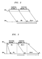
- FIG. 2 a diagram illustrates the transmission of consecutive time-stamped packets without PDV, but with different clock source frequencies, according to an embodiment of the present invention.
- An initial packet is time-stamped with So at a first clock source at a transmit node 202.
- the initial packet is time-stamped with R 0 by a second clock source.
- a subsequent packet in a transfer queue is time-stamped with S 1 at transmit node 202, and upon arriving at receive node 204, the packet is time-stamped with R 1 .
- the first transmit time difference, dS 1 is calculated by subtracting the first transmit time stamp So from the second transmit time stamp S 1 .
- the first receive time difference, dR 1 is calculated by subtracting the first receive time stamp R 0 from the second receive time stamp R 1 . Similar interval calculations are performed for additional packets in the transfer queue, such as, for S 2 , R 2 , respectively, to determine a next transmit and receive time difference, dS 2 , dR 2 , respectively.
- FIG. 3 a diagram illustrates the transmission of consecutive time-stamped packets with PDV and identical clock source frequencies, according to an embodiment of the present invention.
- FIG. 3 provides a similar illustration to that of FIG. 2 ; however LPDV is illustrated.
- An initial packet is time-stamped with So from a first clock source at a transmit node 302, and R 0 from a second clock source at a receive node 304.
- subsequent packets are time-stamped with S 1 , R 1 and S 2 , R 2 , respectively.
- FIG. 3 differs from FIG. 2 in that there is increasing propagation delay, which is shown in the changing of the packet transfer angle from transmit node 302 to receive node 304.
- PDV may be illustrated where the ratio dRn/dSn fluctuates randomly, or as shown in FIG. 3 , the ratio may remain the same for consecutive intervals, however, it is a constant that is not proportional to the relative difference in frequency. Because the frequencies are equal in the illustrative embodiment of FIG. 3 , the relative difference in frequency is 1; however the ratio is greater than 1 as a result of LPDV. Such a condition may degrade frequency synchronization through the introduction of a false correction.
- FIG. 4 a flow diagram illustrates a clock synchronization methodology in a packet network, according to an embodiment of the present invention.
- the methodology begins in block 402 where transmit and receive time stamps are continuously provided for a plurality of packets in a transfer queue.
- the transmit time stamps are provided at the transmit node in accordance with a transmit clock
- the receive time stamps are provided at the receive node in accordance with a receive clock.
- the acceptance window allows for a tolerated error in numerical calculations due to some floor of PDV that is completely random and cannot be reduced to null. It is also allows for time stamping in accuracy at both transmit and receive nodes and other random delay noise encountered in the network. This acceptance window parameter is specific to each network and the equipment used, and can be determined through experimental statistical measurements.
- the acceptance window is increased when it is determined that consecutive intervals of transferred time-stamped packets cannot be found within a specified time period. This indicates that the difference in delay noise was higher than the level accepted by the acceptance window value. The methodology then returns to block 402 for determination of additional intervals of transferred time-stamped packets.
- the consecutive intervals having a difference in delay noise within the defined acceptance window are selected in block 408. It is determined in block 410 if the consecutive intervals pass additional filtering criteria. If the consecutive intervals do not pass the additional filtering criteria, the methodology returns to block 402. In block 412, a correction factor, C n , for the clock source of the receive node is determined based on transmit and receive time stamps of the bounding transferred time-stamped packets of the consecutive intervals. In block 414, the correction factor is applied to the clock source of the receive node for synchronization with the clock source of the transmit node.
- the number of required transferred time-stamped packets for selection of an interval may be increased, the acceptance window for difference in delay noise may be decreased, or both, before the methodology returns to block 402 to repeat and maintain timing synchronization.
- the methodology returns to block 402 to repeat and maintain timing synchronization.
- the algorithm may be processed in the background for every F samples, such as, for example, one second, or 16 samples.
- F can fluctuate as it is just function of when CPU is available to do the calculations. It is basically the difference between the last processed sample in the queue, marked as L, and the actual sample, L+F.
- There will be a circular queue of about 128 locations (D 128).
- the present invention may be implemented in the form of one or more integrated circuits or computer programs.
- a given system node in accordance with the invention may be implemented as one or more integrated circuits comprising at least one processor and at least one memory. Numerous other configurations are possible.
- a plurality of identical die is typically formed in a repeated pattern on a surface of a semiconductor wafer.
- Each die includes a device described herein, and may include other structures or circuits.
- the individual die are cut or diced from the wafer, then packaged as an integrated circuit.
- One skilled in the art would know how to dice wafers and package die to produce integrated circuits. Integrated circuits so manufactured are considered part of this invention.
Landscapes
- Engineering & Computer Science (AREA)
- Computer Networks & Wireless Communication (AREA)
- Signal Processing (AREA)
- Health & Medical Sciences (AREA)
- Cardiology (AREA)
- General Health & Medical Sciences (AREA)
- Environmental & Geological Engineering (AREA)
- Synchronisation In Digital Transmission Systems (AREA)
- Data Exchanges In Wide-Area Networks (AREA)
Applications Claiming Priority (2)
| Application Number | Priority Date | Filing Date | Title |
|---|---|---|---|
| US11/536,989 US7839897B2 (en) | 2006-09-29 | 2006-09-29 | Methods and apparatus for unidirectional timing message transport over packet networks |
| PCT/US2007/067900 WO2008042464A1 (en) | 2006-09-29 | 2007-05-01 | Methods and apparatus for unidirectional timing message transport over packet networks |
Publications (2)
| Publication Number | Publication Date |
|---|---|
| EP2067305A1 EP2067305A1 (en) | 2009-06-10 |
| EP2067305B1 true EP2067305B1 (en) | 2012-08-15 |
Family
ID=38962702
Family Applications (1)
| Application Number | Title | Priority Date | Filing Date |
|---|---|---|---|
| EP07761657A Active EP2067305B1 (en) | 2006-09-29 | 2007-05-01 | Methods and apparatus for unidirectional timing message transport over packet networks |
Country Status (7)
Families Citing this family (23)
| Publication number | Priority date | Publication date | Assignee | Title |
|---|---|---|---|---|
| US7839897B2 (en) | 2006-09-29 | 2010-11-23 | Agere Systems Inc. | Methods and apparatus for unidirectional timing message transport over packet networks |
| DE102008039793A1 (de) * | 2008-08-26 | 2010-03-04 | Siemens Aktiengesellschaft | Verfahren zur Taktsynchronisierung in einem Kommunikationsnetz und Kommunikationsnetz |
| US8416812B2 (en) | 2008-09-22 | 2013-04-09 | Codrut Radu Radulescu | Network timing synchronization systems |
| EP2359510B1 (en) * | 2008-10-24 | 2012-10-10 | Telefonaktiebolaget L M Ericsson (PUBL) | Method and device for packet network synchronization |
| EP2228927A1 (en) * | 2009-03-12 | 2010-09-15 | Alcatel Lucent | Method for processing distributed data having a chosen type for synchronizing communication nodes of a data packet network, and associated device |
| GB0908884D0 (en) * | 2009-05-22 | 2009-07-01 | Zarlink Semiconductor Inc | Time recovery over packet networks |
| CN102045828A (zh) * | 2009-10-22 | 2011-05-04 | 中兴通讯股份有限公司 | 一种发送语音信息的方法和设备 |
| CN101719867B (zh) * | 2009-11-23 | 2012-07-25 | 中兴通讯股份有限公司 | 一种包交换网络中的时钟恢复方法及系统 |
| JP2011217062A (ja) * | 2010-03-31 | 2011-10-27 | Sony Corp | カメラシステム、信号遅延量調整方法及びプログラム |
| EP2445127A1 (fr) * | 2010-10-22 | 2012-04-25 | Alcatel Lucent | Procédé non intrusif de synchronisation d'horloges maître et esclave d'un réseau à commutation de paquets, et dispositifs de synchronisation associés |
| CN102111259A (zh) * | 2011-03-03 | 2011-06-29 | 北京航空航天大学 | 天基路由交换系统数据同步传输方法、装置和系统 |
| CN103814338A (zh) * | 2011-07-20 | 2014-05-21 | 航空网络公司 | 网络同步的系统和方法 |
| US20130077641A1 (en) * | 2011-09-22 | 2013-03-28 | Harley F. Burger, Jr. | Systems, Circuits and Methods for Time Stamp Based One-Way Communications |
| EP2782272B1 (en) * | 2011-11-17 | 2022-05-04 | ZTE Corporation | Method and apparatus for packet timing recovery |
| JP6214008B2 (ja) * | 2012-01-04 | 2017-10-18 | マーベル ワールド トレード リミテッド | 時間認識デバイス間で時間情報を通信する方法および装置 |
| EP2618502A1 (en) * | 2012-01-19 | 2013-07-24 | ABB Technology AG | Data transmission over packet switched network |
| US9106352B2 (en) * | 2012-02-27 | 2015-08-11 | Telefonaktiebolaget L M Ericsson (Publ) | Frequency distribution using precision time protocol |
| US8681772B2 (en) * | 2012-05-11 | 2014-03-25 | Vitesse Semiconductor Corporation | Timing synchronization for networks with radio links |
| US9664539B2 (en) * | 2012-11-30 | 2017-05-30 | Blackberry Limited | Time stamping a sensor sample |
| US20170195980A1 (en) * | 2015-12-31 | 2017-07-06 | Bose Corporation | Synchronizing clocks in a network |
| ES3023683T3 (en) | 2016-12-06 | 2025-06-02 | Ericsson Telefon Ab L M | Method and apparatus for latency monitoring |
| EP3584780B1 (en) * | 2017-02-17 | 2021-10-13 | Nippon Telegraph And Telephone Corporation | Sensing system and time stamp correction method |
| EP3382918B1 (en) * | 2017-03-30 | 2022-09-28 | ADVA Optical Networking SE | System and method of clock management in a packet data network |
Family Cites Families (15)
| Publication number | Priority date | Publication date | Assignee | Title |
|---|---|---|---|---|
| US5533021A (en) * | 1995-02-03 | 1996-07-02 | International Business Machines Corporation | Apparatus and method for segmentation and time synchronization of the transmission of multimedia data |
| JP3134048B2 (ja) * | 1996-03-07 | 2001-02-13 | 三菱電機株式会社 | クロック再生装置およびクロック再生方法 |
| JPH10210019A (ja) * | 1997-01-21 | 1998-08-07 | Mitsubishi Electric Corp | クロック再生装置およびクロック再生方法 |
| JP3358528B2 (ja) * | 1998-03-27 | 2002-12-24 | ヤマハ株式会社 | 通信装置及び通信方法 |
| US7103124B1 (en) * | 1999-12-30 | 2006-09-05 | Telefonaktiebolaget Lm Ericsson (Publ) | Synchronization of nodes |
| US7068746B1 (en) * | 2000-03-01 | 2006-06-27 | Lucent Technologies Inc. | Base station transceiver to radio network controller synchronization filtering function |
| JP3417392B2 (ja) * | 2000-09-08 | 2003-06-16 | ヤマハ株式会社 | 同期制御装置 |
| US6898213B1 (en) * | 2000-10-16 | 2005-05-24 | Iprad Ltd. | Circuit emulation service (CES) over IP |
| JP4623867B2 (ja) * | 2001-06-18 | 2011-02-02 | ティーオーエー株式会社 | 受信装置及び受信再生方法 |
| US7043651B2 (en) | 2001-09-18 | 2006-05-09 | Nortel Networks Limited | Technique for synchronizing clocks in a network |
| JP3655249B2 (ja) * | 2002-03-05 | 2005-06-02 | 松下電器産業株式会社 | データ受信再生方法およびデータ通信装置 |
| GB2392588A (en) | 2002-08-24 | 2004-03-03 | Zarlink Semiconductor Ltd | Adaptive TDM clock recovery using timestamps |
| US20040223515A1 (en) * | 2003-01-14 | 2004-11-11 | Rygielski Ronald E. | Method and apparatus for the synchronization of a system time of a communications network with a clock reference |
| KR100640492B1 (ko) * | 2004-08-31 | 2006-10-30 | 삼성전자주식회사 | 네트워크의 가용 대역폭 측정 방법 |
| US7839897B2 (en) | 2006-09-29 | 2010-11-23 | Agere Systems Inc. | Methods and apparatus for unidirectional timing message transport over packet networks |
-
2006
- 2006-09-29 US US11/536,989 patent/US7839897B2/en active Active
-
2007
- 2007-05-01 CA CA002660030A patent/CA2660030A1/en not_active Abandoned
- 2007-05-01 EP EP07761657A patent/EP2067305B1/en active Active
- 2007-05-01 KR KR1020097006449A patent/KR101323956B1/ko not_active Expired - Fee Related
- 2007-05-01 CN CN2007800354663A patent/CN101517968B/zh not_active Expired - Fee Related
- 2007-05-01 WO PCT/US2007/067900 patent/WO2008042464A1/en active Application Filing
- 2007-05-01 JP JP2009530484A patent/JP5330247B2/ja not_active Expired - Fee Related
Also Published As
| Publication number | Publication date |
|---|---|
| JP5330247B2 (ja) | 2013-10-30 |
| KR20090076901A (ko) | 2009-07-13 |
| CA2660030A1 (en) | 2008-04-10 |
| CN101517968A (zh) | 2009-08-26 |
| KR101323956B1 (ko) | 2013-12-19 |
| WO2008042464A1 (en) | 2008-04-10 |
| EP2067305A1 (en) | 2009-06-10 |
| US20080080567A1 (en) | 2008-04-03 |
| CN101517968B (zh) | 2012-08-22 |
| US7839897B2 (en) | 2010-11-23 |
| JP2010505362A (ja) | 2010-02-18 |
Similar Documents
| Publication | Publication Date | Title |
|---|---|---|
| EP2067305B1 (en) | Methods and apparatus for unidirectional timing message transport over packet networks | |
| US7876791B2 (en) | Synchronizing apparatus and method in packet network | |
| US8451867B2 (en) | Network time protocol precision timestamping service | |
| US8644348B2 (en) | Method for generating a robust timing correction in timing transfer systems | |
| EP3284217B1 (en) | Methods, systems, and computer readable medium for synchronizing timing among network interface cards (nics) in a network equipment test device | |
| EP2342850B1 (en) | A method for synchronizing clocks in a communication network | |
| US8427963B2 (en) | Method and system for analyzing and qualifying routes in packet networks | |
| US8467487B2 (en) | Network synchronization method and apparatus for performing time synchronization between nodes | |
| EP2490357A2 (en) | A method of time synchronization of free running nodes in an avionics network | |
| US7120090B2 (en) | Method of determining a timing offset between a first clock and a second clock in a communications network | |
| US9270607B2 (en) | Method and devices for packet selection | |
| US20190260568A1 (en) | Methods, systems, and computer readable media for transmit timestamp autocalibration | |
| EP2599247B1 (en) | Method and device for processing data on a connection between two nodes of a communication network | |
| EP3334067A1 (en) | Synchronization device and system for communication networks | |
| US7103514B1 (en) | Filter turning point detection | |
| EP2627040A1 (en) | Method for eliminating systematical error components in a set of one-way delay measurement results for communications between two or more computing systems in a communication network, apparatus for performing the method and computer program product | |
| EP3080951B1 (en) | Method and devices for packet selection | |
| Kim et al. | End-to-end one-way delay estimation using one-way delay variation and round-trip time | |
| HK1126050A1 (en) | Using travel-time as means for improving the accuracy of simple network time protocol | |
| HK1126050B (en) | Using travel-time as means for improving the accuracy of simple network time protocol |
Legal Events
| Date | Code | Title | Description |
|---|---|---|---|
| PUAI | Public reference made under article 153(3) epc to a published international application that has entered the european phase |
Free format text: ORIGINAL CODE: 0009012 |
|
| 17P | Request for examination filed |
Effective date: 20090331 |
|
| AK | Designated contracting states |
Kind code of ref document: A1 Designated state(s): AT BE BG CH CY CZ DE DK EE ES FI FR GB GR HU IE IS IT LI LT LU LV MC MT NL PL PT RO SE SI SK TR |
|
| AX | Request for extension of the european patent |
Extension state: AL BA HR MK RS |
|
| RIN1 | Information on inventor provided before grant (corrected) |
Inventor name: RADULESCU, CODRUT, RADU |
|
| 17Q | First examination report despatched |
Effective date: 20091214 |
|
| DAX | Request for extension of the european patent (deleted) | ||
| RBV | Designated contracting states (corrected) |
Designated state(s): DE FI GB |
|
| GRAP | Despatch of communication of intention to grant a patent |
Free format text: ORIGINAL CODE: EPIDOSNIGR1 |
|
| GRAS | Grant fee paid |
Free format text: ORIGINAL CODE: EPIDOSNIGR3 |
|
| GRAA | (expected) grant |
Free format text: ORIGINAL CODE: 0009210 |
|
| AK | Designated contracting states |
Kind code of ref document: B1 Designated state(s): DE FI GB |
|
| REG | Reference to a national code |
Ref country code: GB Ref legal event code: FG4D |
|
| REG | Reference to a national code |
Ref country code: DE Ref legal event code: R096 Ref document number: 602007024798 Country of ref document: DE Effective date: 20121011 |
|
| PLBE | No opposition filed within time limit |
Free format text: ORIGINAL CODE: 0009261 |
|
| STAA | Information on the status of an ep patent application or granted ep patent |
Free format text: STATUS: NO OPPOSITION FILED WITHIN TIME LIMIT |
|
| 26N | No opposition filed |
Effective date: 20130516 |
|
| REG | Reference to a national code |
Ref country code: DE Ref legal event code: R097 Ref document number: 602007024798 Country of ref document: DE Effective date: 20130516 |
|
| PGFP | Annual fee paid to national office [announced via postgrant information from national office to epo] |
Ref country code: FI Payment date: 20140512 Year of fee payment: 8 |
|
| PGFP | Annual fee paid to national office [announced via postgrant information from national office to epo] |
Ref country code: GB Payment date: 20150424 Year of fee payment: 9 |
|
| PG25 | Lapsed in a contracting state [announced via postgrant information from national office to epo] |
Ref country code: FI Free format text: LAPSE BECAUSE OF NON-PAYMENT OF DUE FEES Effective date: 20150501 |
|
| REG | Reference to a national code |
Ref country code: DE Ref legal event code: R082 Ref document number: 602007024798 Country of ref document: DE Representative=s name: DILG, HAEUSLER, SCHINDELMANN PATENTANWALTSGESE, DE Ref country code: DE Ref legal event code: R082 Ref document number: 602007024798 Country of ref document: DE Representative=s name: DILG HAEUSLER SCHINDELMANN PATENTANWALTSGESELL, DE Ref country code: DE Ref legal event code: R081 Ref document number: 602007024798 Country of ref document: DE Owner name: AVAGO TECHNOLOGIES GENERAL IP (SINGAPORE) PTE., SG Free format text: FORMER OWNER: AGERE SYSTEMS, INC., ALLENTOWN, PA., US Ref country code: DE Ref legal event code: R081 Ref document number: 602007024798 Country of ref document: DE Owner name: AVAGO TECHNOLOGIES INTERNATIONAL SALES PTE. LI, SG Free format text: FORMER OWNER: AGERE SYSTEMS, INC., ALLENTOWN, PA., US |
|
| REG | Reference to a national code |
Ref country code: DE Ref legal event code: R082 Ref document number: 602007024798 Country of ref document: DE Representative=s name: DILG, HAEUSLER, SCHINDELMANN PATENTANWALTSGESE, DE Ref country code: DE Ref legal event code: R082 Ref document number: 602007024798 Country of ref document: DE Representative=s name: DILG HAEUSLER SCHINDELMANN PATENTANWALTSGESELL, DE Ref country code: DE Ref legal event code: R081 Ref document number: 602007024798 Country of ref document: DE Owner name: AVAGO TECHNOLOGIES GENERAL IP (SINGAPORE) PTE., SG Free format text: FORMER OWNER: AGERE SYSTEMS LLC (N.D.GES.D. STAATES DELAWARE), ALLENTOWN, PA., US Ref country code: DE Ref legal event code: R081 Ref document number: 602007024798 Country of ref document: DE Owner name: AVAGO TECHNOLOGIES INTERNATIONAL SALES PTE. LI, SG Free format text: FORMER OWNER: AGERE SYSTEMS LLC (N.D.GES.D. STAATES DELAWARE), ALLENTOWN, PA., US |
|
| GBPC | Gb: european patent ceased through non-payment of renewal fee |
Effective date: 20160501 |
|
| PG25 | Lapsed in a contracting state [announced via postgrant information from national office to epo] |
Ref country code: GB Free format text: LAPSE BECAUSE OF NON-PAYMENT OF DUE FEES Effective date: 20160501 |
|
| REG | Reference to a national code |
Ref country code: DE Ref legal event code: R081 Ref document number: 602007024798 Country of ref document: DE Owner name: AVAGO TECHNOLOGIES INTERNATIONAL SALES PTE. LI, SG Free format text: FORMER OWNER: AVAGO TECHNOLOGIES GENERAL IP (SINGAPORE) PTE. LTD., SINGAPORE, SG Ref country code: DE Ref legal event code: R082 Ref document number: 602007024798 Country of ref document: DE Representative=s name: DILG, HAEUSLER, SCHINDELMANN PATENTANWALTSGESE, DE Ref country code: DE Ref legal event code: R082 Ref document number: 602007024798 Country of ref document: DE Representative=s name: DILG HAEUSLER SCHINDELMANN PATENTANWALTSGESELL, DE |
|
| REG | Reference to a national code |
Ref country code: DE Ref legal event code: R079 Ref document number: 602007024798 Country of ref document: DE Free format text: PREVIOUS MAIN CLASS: H04L0012260000 Ipc: H04L0043000000 |
|
| PGFP | Annual fee paid to national office [announced via postgrant information from national office to epo] |
Ref country code: DE Payment date: 20240510 Year of fee payment: 18 |