EP2066468B2 - Procédé et appareil pour la densification de la surface d'une pièce frittée - Google Patents
Procédé et appareil pour la densification de la surface d'une pièce frittée Download PDFInfo
- Publication number
- EP2066468B2 EP2066468B2 EP07800161.7A EP07800161A EP2066468B2 EP 2066468 B2 EP2066468 B2 EP 2066468B2 EP 07800161 A EP07800161 A EP 07800161A EP 2066468 B2 EP2066468 B2 EP 2066468B2
- Authority
- EP
- European Patent Office
- Prior art keywords
- die
- sintered part
- sintered
- section
- pressing
- Prior art date
- Legal status (The legal status is an assumption and is not a legal conclusion. Google has not performed a legal analysis and makes no representation as to the accuracy of the status listed.)
- Active
Links
- 238000000034 method Methods 0.000 title claims description 60
- 238000003825 pressing Methods 0.000 claims description 61
- 238000005056 compaction Methods 0.000 claims description 14
- 230000005489 elastic deformation Effects 0.000 claims description 9
- 230000007704 transition Effects 0.000 claims description 6
- 230000003247 decreasing effect Effects 0.000 claims description 5
- 125000006850 spacer group Chemical group 0.000 claims description 4
- 238000005245 sintering Methods 0.000 claims description 3
- 238000011144 upstream manufacturing Methods 0.000 claims 1
- 238000003780 insertion Methods 0.000 description 17
- 230000037431 insertion Effects 0.000 description 17
- 230000008569 process Effects 0.000 description 13
- 238000007906 compression Methods 0.000 description 12
- 230000006835 compression Effects 0.000 description 11
- 230000000694 effects Effects 0.000 description 11
- 230000007423 decrease Effects 0.000 description 8
- 238000004519 manufacturing process Methods 0.000 description 8
- 239000000843 powder Substances 0.000 description 8
- 230000004323 axial length Effects 0.000 description 7
- 239000000463 material Substances 0.000 description 5
- 238000013461 design Methods 0.000 description 4
- 238000004898 kneading Methods 0.000 description 4
- 230000008859 change Effects 0.000 description 3
- 238000000280 densification Methods 0.000 description 3
- 238000001125 extrusion Methods 0.000 description 3
- 238000011049 filling Methods 0.000 description 3
- 239000002184 metal Substances 0.000 description 3
- 229910052751 metal Inorganic materials 0.000 description 3
- 230000009467 reduction Effects 0.000 description 3
- WFKWXMTUELFFGS-UHFFFAOYSA-N tungsten Chemical compound [W] WFKWXMTUELFFGS-UHFFFAOYSA-N 0.000 description 3
- 229910052721 tungsten Inorganic materials 0.000 description 3
- 239000010937 tungsten Substances 0.000 description 3
- 230000002411 adverse Effects 0.000 description 2
- 238000004873 anchoring Methods 0.000 description 2
- 238000005452 bending Methods 0.000 description 2
- 230000002349 favourable effect Effects 0.000 description 2
- 239000010410 layer Substances 0.000 description 2
- 239000011159 matrix material Substances 0.000 description 2
- 238000002844 melting Methods 0.000 description 2
- 230000008018 melting Effects 0.000 description 2
- 239000002923 metal particle Substances 0.000 description 2
- 230000000750 progressive effect Effects 0.000 description 2
- 238000007493 shaping process Methods 0.000 description 2
- 208000030814 Eating disease Diseases 0.000 description 1
- 208000019454 Feeding and Eating disease Diseases 0.000 description 1
- 230000009471 action Effects 0.000 description 1
- 230000009286 beneficial effect Effects 0.000 description 1
- 238000004364 calculation method Methods 0.000 description 1
- 238000010276 construction Methods 0.000 description 1
- 235000014632 disordered eating Nutrition 0.000 description 1
- 239000012530 fluid Substances 0.000 description 1
- 238000005242 forging Methods 0.000 description 1
- 238000000227 grinding Methods 0.000 description 1
- 238000007654 immersion Methods 0.000 description 1
- 238000012423 maintenance Methods 0.000 description 1
- 238000005259 measurement Methods 0.000 description 1
- 238000012545 processing Methods 0.000 description 1
- 230000008929 regeneration Effects 0.000 description 1
- 238000011069 regeneration method Methods 0.000 description 1
- 239000007787 solid Substances 0.000 description 1
- 238000007711 solidification Methods 0.000 description 1
- 230000008023 solidification Effects 0.000 description 1
- 239000002344 surface layer Substances 0.000 description 1
- 229910052724 xenon Inorganic materials 0.000 description 1
- FHNFHKCVQCLJFQ-UHFFFAOYSA-N xenon atom Chemical compound [Xe] FHNFHKCVQCLJFQ-UHFFFAOYSA-N 0.000 description 1
Images


Classifications
-
- B—PERFORMING OPERATIONS; TRANSPORTING
- B22—CASTING; POWDER METALLURGY
- B22F—WORKING METALLIC POWDER; MANUFACTURE OF ARTICLES FROM METALLIC POWDER; MAKING METALLIC POWDER; APPARATUS OR DEVICES SPECIALLY ADAPTED FOR METALLIC POWDER
- B22F3/00—Manufacture of workpieces or articles from metallic powder characterised by the manner of compacting or sintering; Apparatus specially adapted therefor ; Presses and furnaces
- B22F3/12—Both compacting and sintering
- B22F3/16—Both compacting and sintering in successive or repeated steps
- B22F3/164—Partial deformation or calibration
-
- B—PERFORMING OPERATIONS; TRANSPORTING
- B22—CASTING; POWDER METALLURGY
- B22F—WORKING METALLIC POWDER; MANUFACTURE OF ARTICLES FROM METALLIC POWDER; MAKING METALLIC POWDER; APPARATUS OR DEVICES SPECIALLY ADAPTED FOR METALLIC POWDER
- B22F3/00—Manufacture of workpieces or articles from metallic powder characterised by the manner of compacting or sintering; Apparatus specially adapted therefor ; Presses and furnaces
- B22F3/02—Compacting only
- B22F3/03—Press-moulding apparatus therefor
-
- Y—GENERAL TAGGING OF NEW TECHNOLOGICAL DEVELOPMENTS; GENERAL TAGGING OF CROSS-SECTIONAL TECHNOLOGIES SPANNING OVER SEVERAL SECTIONS OF THE IPC; TECHNICAL SUBJECTS COVERED BY FORMER USPC CROSS-REFERENCE ART COLLECTIONS [XRACs] AND DIGESTS
- Y10—TECHNICAL SUBJECTS COVERED BY FORMER USPC
- Y10T—TECHNICAL SUBJECTS COVERED BY FORMER US CLASSIFICATION
- Y10T29/00—Metal working
- Y10T29/49—Method of mechanical manufacture
- Y10T29/49462—Gear making
- Y10T29/49467—Gear shaping
- Y10T29/49474—Die-press shaping
Definitions
- the invention relates to a method for surface compacting of sintered parts with the features of claim 1.
- Sintered parts, ie workpieces made of pressed and sintered metal powder have long been an alternative to cast or from the fully machined workpieces.
- more or less pronounced porosity of the sintered parts has a negative effect on the flexural strength and the wear resistance, which limits, for example, the use of powder-metallurgically produced gears in high-load gearboxes.
- a method using a die tool for this purpose is known from US 6,168,754 B1 known.
- a sintered blank that is pressed from powder metal and then sintered part is compacted on its outer surface by this is pressed by a multi-stage die tool.
- the die tool comprises a plurality of axially spaced die plates with die openings, which substantially correspond to the shape of the sintered blank, but whose inner diameter decreases gradually and is smaller than the outer diameter of the sintered blank.
- the outer periphery of the sintered part is plastically and elastically deformed, whereby the surface is compacted and the sintered part receives its final dimension.
- the distances between the die plates allow the sintered part to expand by expanding a portion of the elastic deformations after each die plate.
- the sintered part undergoes intermediate relief after each die plate, as a result of which a compressive residual stress remaining after deformation in the sintered part is built up in stages.
- a method for producing tungsten caps for electrodes of xenon lamps is known.
- the tungsten caps are produced by forging from a sintered tungsten body, which is formed in a first step, the inner contour and then the excess material is removed on the outer contour.
- a die is used which has an insertion section, a subsequent conical pressing area and a subsequent withdrawal area thereon.
- the US 2,957,232 A describes a method for producing a sintered part, according to which a pressed and sintered blank in an extrusion mold is shaped to the finished sintered part.
- the extrusion die has a first cylindrical portion having a larger diameter than the blank.
- the first section of the extrusion mold is followed by a conical section and, adjacent to this, a second cylindrical section with a smaller diameter compared to the first cylindrical section.
- the blank is partially pressed from the first to the second cylindrical section for shaping.
- a method for producing a contact pin from a sinter powder includes introducing a sintered blank of predetermined shape into a die having a shaping cavity of larger diameter than the blank.
- the blank is compacted by application of pressure in this forming cavity and thereby applied to the wall of the forming cavity.
- the WO 03/020460 A2 describes a method for producing a metallic sintered part, in particular a ball raceway having inner joint part of a shaft joint, wherein powder is filled into a filling space, the filling space is limited by a die, at least one forming mandrel and a Fandorn arranged opposite this, a center mandrel, at least one lower and one Oberstempel, wherein the powder is pressed in the filling space by pressure on the upper and / or lower punch to a green compact, ejected and sintered.
- the object of the invention is to provide a method for surface compacting a sintered part, which offers the possibility of a high compression of a sintered part surface while at the same time a simple tool design.
- the compaction of the surface does not have to take place on the entire outer circumference of a sintered part, but can be limited to subsections of the outer surface.
- the term inner diameter in this application is not limited to the diameter of a cylinder, but is generally understood to mean the distance between facing press surfaces as measured between cooperating pressing surfaces.
- the inner diameter within a die section is constant, i. that the die section does not taper.
- the pressing surface of the die section acting on it is a circular-cylindrical surface with generatrixes parallel to the axis. Since a circular cylindrical die portion is relatively easy to manufacture, a die tool for circular cylindrical sintered parts can be produced by simple means, when all die sections each have constant inner diameters.
- the transition from a die section to a subsequent die section is formed with at least one rounding, wherein in the pressing direction to a concave curve connects a convex curve.
- the sintered part In a die tool in which the last die section terminates inside the tool body, the sintered part must be removed after reversing the motion through the first die opening from the die tool, but the method can be advantageously supplemented by the sintered part by a second die opening opposite the first die opening the die tool is moved.
- the relative movement between the sintered part and the die tool can advantageously be rectilinear or in a screwing motion.
- Sintered parts whose contact surfaces are rotationally symmetrical with respect to the axis can be pressed both rectilinearly and with a screwing motion or a combination thereof through the die tool.
- Sintered parts whose contact surfaces are formed by screw surfaces must be pressed in a screwing motion by the die tool.
- additional tangential stress components can be introduced into the surface of the sintered part by a rotating movement, which can favorably influence the compacting process.
- the movement is carried out by the sintered part and / or the die tool.
- the sintered part is moved from the first die section to the last die section, but it can be advantageous for structural reasons or for procedural reasons to let the movement be performed by the die tool or to drive both the sintered part and the die tool.
- the same drive concepts but also different drive concepts for the two components can be used, e.g.
- the sintered part or the die tool performs a smooth, slow movement
- the die tool or die performs an intermittent fast movement, resulting in a pulsating relative speed, which may be advantageous when a relative movement stop is undesirable and the movement from one Matrizenabites to the subsequent section with higher speed to be executed.
- the sintered part can be pressed and pulled both in the axial direction, and the introduction of correspondingly high tensile forces should be avoided in the axial direction of small dimensions of the sintered part due to the risk of breakage and should remain limited to sintered parts with axially larger dimensions.
- Optimum introduction of the required forces into the sintered part is achieved when the sintered part is placed between two pressure elements, e.g. two stamping associated with drive means, is largely pressurized over the entire surface axially.
- the movement through the die tool can also be carried out with a reversal of the direction without the risk of the sintered part being damaged by the occurrence of higher tensile stresses.
- the sintered part can be clamped between two pressure punches whose shape substantially corresponds to the matrix shape.
- An advantageous variant of the method can also be that the sintered part is removed from the mold after reaching the last die section through the first die opening, i. the direction of movement is reversed after reaching the last die section. Due to the fact that the part removal onto the die tool takes place at the same position as the parts feed before the process is carried out, this variant can be advantageous for the part flow.
- the last die section has an influence on the finished size of the sintered part achieved after the process, it is advantageous if the sintered part in the last die section is compressed to an inner diameter which reduces a nominal dimension of a sintered part by the value of the elastic deformation of the sintered part caused by the pressing forces Sintered parts corresponds to this inner diameter. Since the plastic deformation takes place substantially on the outer surface of the sintered body, the elastic portion of the deformation can be estimated relatively well by calculation methods, and therefore it is possible to form the last die portion such that the sintered body after being removed from the last die portion substantially Has nominal size. The dimensional accuracy achieved thereby can subsequent processing steps for further approximation the finished measure to a nominal size, eg make a grinding process unnecessary.
- the sintered part is introduced into an insertion section arranged in front of the first die opening, which has an insertion diameter which is greater than a rough measurement of the sintered part on its outer surface.
- This insertion section may e.g. be formed by an additional insertion plate, which is arranged in the pressing direction before the first die portion, and has an opening which is larger by a small functional clearance, as the Rohabstoryen the sintered part on its outer surface. This results in reliable positioning and guidance of the sintered part before and during the pressing into the first die section.
- the sintered part is moved after the last die section into a subsequent calibration section, which has a calibration diameter corresponding to a desired diameter of the sintered part on its outer surface.
- the calibration section can connect directly to the last die section, or it can also be provided with a gap between the last die section and the dimensional calibration section, whereby an intermediate relief of the sintered part is possible before the calibration.
- a possible embodiment of the method consists in that a sequence of sintered parts with or without pressure-resistant spacer elements each arranged between two sintered parts is moved by the die tool.
- the method is carried out approximately at room temperature, it may be advantageous if the sintered part has a temperature below the melting temperature, in particular in a range of 100 ° C. or 200 ° C. below the melting temperature, during the process. lies. Due to the increased temperature compared to the room temperature in the process execution of the process of surface compaction and thereby occurring change of the structure can be facilitated, which on the one hand, the surface properties of the finished sintered part can be favorably influenced and the forces required for the process performance can be reduced.
- the sintered part is designed as a bearing bush, as a bearing shell, as a gear wheel, as a sprocket, as a toothed belt wheel or as a cam element.
- the achievable with the method surface compaction and increasing the bending strength proves to be particularly advantageous in these applications of a sintered part.
- the sintered part can be moved through the entire die tool, in particular pressed.
- an axial die section length is greater than an axial contact face length. This ensures that a sintered part or its contact surface is wholly introduced into a die section before a leading edge of the sintered part or the contact surface already undergoes the deformation by the subsequent die section.
- the for the movement of the Sintered parts required force is thus occasionally largely constant, whereby a phase-wise, constant movement speed relatively easy, eg via a pressure control of a fluid cylinder which acts on the sintered part, can be achieved.
- the axial die section length of the last die section may be less than 30% of the contact surface length of the sintered part.
- Last Matrizenabites causes a limited to a small proportion of the contact surface kneading effect, which can increase the effectiveness of surface compaction in addition.
- this Matrizenabites be conical, whereby the kneading effect is enhanced.
- this is advantageous if the sintered part is removed again from the die tool through the first die opening.
- the total axial length of all die sections is smaller in total than the axial contact surface length of the sintered part.
- the surface compression takes place only on a small part of the contact surface and the influences of the axial sliding friction are thereby lower compared to a longer tool.
- the inner diameter in the last die section has a value which reduces a nominal dimension of the sintered part by the value of the elastic deformation of the sintered part due to the pressing forces this inner diameter corresponds.
- the elastic deformation of the sintered part can be estimated for this purpose with sufficiently good accuracy, whereby the sintered part after passing through the last die section has at least approximately its nominal dimension.
- the inner contour is rotationally symmetrical with respect to the axis.
- the surface of a circular cylindrical sintered part can be compacted with a single process implementation over its entire circumference, while in only partially executed as a circular cylinder pressing surfaces a two or more times performing the pressing operation with intermediate rotation of the sintered part would be required.
- the inner contour is rotationally symmetrical with respect to the axis, whereby the die tool, in particular for the surface compression of sintered gears, toothed belt wheels or sprockets is applicable.
- the method is also applicable to irregularly shaped sintered parts, when the pressing surface of a Matrizenabitess is formed as a general cylindrical surface. The application is therefore not limited to rotational or rotationally symmetrical sintered parts.
- the pressing surface of a die portion can also be formed by a screw surface, whereby the surfaces of a helical gear can be compressed when the movement is performed by the die tool with a screwing movement.
- the pressing surfaces of the die sections are each formed at least in sections by internal straight toothing.
- the tooth flanks extend in the axial direction.
- the pressing surfaces of the die sections are each formed, at least in sections, by internal helical gearing, helical spur gears or spur gear segments can also be surface-compacted.
- the die tool can be composed of several die parts both in the axial and in the radial direction, but an extremely robust design is achieved if the die tool is made in one piece.
- the introduction of a sintered part into the die tool is substantially facilitated if, in the direction of the second die opening, before the first die section, an insertion section whose inner diameter is larger than a raw diameter of the sintered part is arranged.
- the insertion section corresponds to a die section, but with a clearance fit instead of a press fit to the sintered part.
- the calibration can connect directly to the last Matrizenabites or be provided therebetween a distance which causes an intermediate relief of the sintered part, which thereby at least partially degrades its elastic deformation by expansion before the actual calibration section.
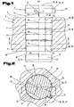
- Fig. 1 3 shows a longitudinal section through a die tool 1 for surface compacting a sintered part 2 by moving it along an axis 3 through the die tool 1.
- This comprises a tool main body 4 which has a first die opening 6 on a tool surface 5, of which several die sections 7 along the axis 3 , 8 and 9 lead into the interior of the tool base 4.
- a first die section 7 adjoins the first die opening 6
- a last die section 9 extends in the illustrated embodiment to an opposing second tool surface 10 and thereby forms a second die opening 11.
- the last die section 9 also in the interior of the tool base 4 end, whereby no second die opening 11 is formed.
- the sintered part 2 must in any case be removed again from the die tool 1 through the first die opening 6.
- the sintered part 2 consists of pressed and subsequently sintered powder metal, the methods and materials for producing such a sintered blank from the prior art are sufficiently known and therefore not further explained.
- the sintered part 2 is designed disc-shaped in the illustrated embodiment and has on an outer surface 12 has a diameter 13, which corresponds to a raw diameter 14 before the surface compression and after the surface compression corresponds to a smaller final diameter 15.
- the surface compacting of the sintered part 2 is carried out by being introduced through the first die opening 6 in the first die section 7 and subsequently in all other die sections 8 and also to the last die section 9, wherein in each die section 7, 8, 9, the outer surface 12 of the sintered part 2 at least on portions of the outer surface 12 against wall surfaces 16 of the die sections 7, 8, 9 is pressed.
- the contact surface 17 may thus by a part of the outer surface 12 or through the entire outer surface 12 may be formed;
- the pressing surface 18 may be formed by a portion of the wall surface 16 or even by the entire wall surface 16, wherein the portion may relate to the axial extent and / or on the extent in the circumferential direction.
- the pressing effect is achieved by an inner diameter 19, which is defined by the clear width between opposing or cooperating sections of the pressing surface 18 of a die section 7, 8, 9, being smaller than the raw diameter 14 of the sintered part 2.
- the term inner diameter 19 is not limited to circular cross-sections to understand, but also as a clear width between co-operating press surface parts that do not necessarily have to go through the axis 3 of the die tool 1.
- the diameter 13 on the sintered part 2 is not limited to radial directions.
- the successive die sections 7, 8, 9 along the axis 3 merge into one another continuously and have from the first die section 7 to the last die section 9 monotonically decreasing inner diameter 19, ie successive inner diameter 19 may be equal or decrease, but not larger ,
- a pressing direction 20 is defined, which is defined by the first Matrizenabêt 7 to the last die section 9 has.
- the movement of the sintered part 2 in the die tool 1 takes place in a straight line in the pressing direction 20 from the first die opening 6 to the last die section 9, followed by removal of the sintered part 2 from the die tool 1 via the second die opening 11 or reversing the direction of movement Pressing direction 20 through the first die opening 6.
- the rectilinear movement in the direction of the axis 3 can also be a rotational movement, e.g. in a rotational direction 21, be superimposed, whereby the sintered part 2 performs a screwing in the die 1.
- sintered parts 2 can also be compacted on their surface with the die workpiece 1, the outer surface 12 of which also comprises screwed surfaces.
- the movement of the sintered part 2 in this case takes place about a screw axis 22 which coincides or is parallel to the axis 3, for example if the screw surface to be compacted on the outer surface 12 of the sintered part 2 is not disposed on the entire circumference of the sintered part 2 and this does not have a rotationally symmetrical basic body.
- the direction of movement of the sintered part 2 in the die tool 1 can, as well as the speed of movement for optimizing the surface compaction, have an arbitrary course and, for example, also include a reversal of the direction of movement, a stoppage of movement, very slow but also very fast movements. Due to the interference fit, which is effective between the contact surfaces 17 and the pressing surfaces 18, compressive stresses, which are oriented substantially perpendicular to the contact surfaces 17, by the movement of the sintered part experiences the contact surface 17 in addition also a sliding friction stress in the axial direction with rectilinear motion or both in the axial and tangential direction in a screwing movement.
- the axial length of the sintered part 2 or the length of its contact surfaces 17 and the axial lengths of the die sections 7, 8, 9 Fig. 1 may be shorter than the contact surface length 24 of the die Sintered parts 2. It is even possible that the contact surface length 24 is greater than the sum of all die sections 7, 8, 9th
- the relative movement between the sintered part 2 and the die tool 1 required for carrying out the method can be effected by moving the sintered part 2 and / or by moving the die tool 1, wherein the sintered part 2 and the die tool 1 are each connected to a suitable drive or a fixed frame ,
- the sintered part 2 leaves the last die section 9 either through the second die opening 11 or after reversal of the direction of movement against the pressing direction 20 through the first die opening 6.
- the elastic deformations of the sintered part 2 which occur during the pressing in may thereby at least partially degrade and the diameter 13 of the sintered part 2 rises from the inner diameter 19 of the last Matrizenabitess 9 by the elastic spring back slightly on the larger end diameter 15, which corresponds as possible to the nominal diameter of the sintered part 2.
- Fig. 1 this is shown with a sintered part 2 shown in dashed lines, which is located in the pressing direction 20 after the last die section 9 and the end diameter 15 is slightly larger than the inner diameter 19 of the last die section.
- Fig. 2 shows a cross section according to the lines II-II in Fig. 1 This is in the illustrated embodiment, not rotationally symmetrical with respect to the axis 3, further extends its contact surface 17, takes place on the surface compression, not over its entire outer circumference, ie that only a portion of its outer surface 12 compacts becomes.
- the stencil tool 1 does not involve the entire wall surface 16 at the compression, but only the pressing surfaces 18, which contact the corresponding contact surfaces 17 of the sintered part 2. It can be seen that in the most general case the compaction of the surface takes place only where an inner contour 25 of a die section 7, 8, 9 defined by the wall surface 16 cooperates with an outer contour 26 defined by the outer surface 12 of the sintered part 2.
- a contact surface 17 on the sintered part 2 can be compressed in all die sections 7, 8, 9 by a corresponding pressing surface 18, but it is also possible that in individual or multiple die sections 7, 8 and or 9 only individual contact surfaces 7 or parts be compacted by the pressing surfaces 18 in single or more die sections 7, 8, 9 are made smaller.
- diameter 13 are considered in the context of the invention, which also extend through the axis 3, but also diameter 13, which correspond to a tooth thickness 27 on an outer toothing of the sintered part 2. Also in this case, opposite contact surfaces 17 of the sintered part 2 are pressed and compacted by opposing pressing surfaces 18 of a die section 7, 8, 9 by monotonically decreasing inner diameter 19.
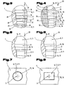
- Fig. 3 shows a section of a longitudinal section through an embodiment of the die tool 1 with four die sections 7, 8, 9, the inner diameter 19 in the pressing direction 20 are gradually smaller.
- the transition from a die section 7, 8 to the adjoining die section 8, 9 can be designed as a chamfer 28, or be provided with a rounding 29, wherein in the pressing direction 20 can connect to a concave curve convex rounding.
- a smooth transition of the sintered part 2 from one die section 7, 8 to the subsequent die section 8, 9 can take place without an unintentional material removal at the sintered part 2 being effected by a sheep-edged step, or the edges breaking off at the transitions of the die tool 1.
- Fig. 4 shows a section of a longitudinal section through an embodiment of the die tool 1, which is not in one piece in this embodiment, but is composed of a plurality of die plates 30. Notwithstanding the execution according to Fig. 3 in which the inner diameters 19 within the die sections 7, 8, 9 are respectively constant, ie are formed by a circular cylindrical surface 31, the die tool 1 has according to FIG Fig. 4 between each two die sections 7 and 8, 8 and 8, or 8 and 9 with circular cylindrical surfaces 31 and a die section 8, which has a cross-sectional taper 32 in the pressing direction 20.
- Fig. 5 1 shows a section from a longitudinal section through a further embodiment of the die tool 1.
- a die section 8 which is arranged between two further die sections 7 and 8, or 8 and 8, or 8 and 9 with circular cylinder surfaces 31, has a tapering surface 35, which has a progressive course in the pressing direction 20, ie the decrease of the inner diameter 19 within the die section 8 in the pressing direction 20 becomes stronger or increases.
- the decrease in the inner diameter 19 is progressive in the region of the taper surface 35.
- Fig. 6 shows a section of a longitudinal section through a further embodiment of the Matrizenwerkmaschines 1, wherein arranged between two Matrizenabitesen 7 and 8, or 8 and 8, or 8 and 9 with a circular cylindrical surface 31 as a wall surface 16, a die section 8 with a tapering surface 35 as a wall surface 16 is, in which the decrease in the inner diameter 19 in the pressing direction is lower, so has a degressive course.
- Fig. 7 shows a plan view of a further embodiment of the die tool 1, in which the inner contour 25 of the wall surface 16 is rotationally symmetrical with respect to the axis 3.
- Fig. 8 1 shows a plan view of a further embodiment of the die tool 1, in which the inner contour 25 of the wall surface 16 of the die sections 7, 8, 9 is rectangular performs.
- the inner contour 25 is therefore only rotationally symmetrical with respect to the axis 3 and suitable for compacting sintered parts with a rectangular cross-section.
- Fig. 9 a plan view of another embodiment of the die tool 1 with an inner contour 25 of the wall surfaces 16 of the die sections 7, 8, 9 which is composed of a circular section, a straight and a toothing.
- the method for compacting the surface of sintered parts 2 is thus not applicable to rotationally symmetrical or rotationally symmetrical outer contours 26 of sintered parts 2, but also for arbitrarily shaped outer contours 26.
- Fig. 10 shows a plan view of a further embodiment of the die tool 1, in which the inner contour 25 of the wall surfaces 16 of the die sections 7, 8, 9 form an internal toothing 36 with which the outer surfaces 12 of a gear can be compressed.
- the inner contour 25 can thereby run straight in the direction of the axis 3, whereby the Matrizenwerkmaschine 1 is suitable for surface compression of straight-toothed gears, the inner contour 25 is in the tool interior, however, not rectilinear, but continues with an additional screwing in the direction of rotation 21, with the die tool 1 gear wheels with helical teeth are surface-compressed.
- the wall surfaces 16 in inner contours 25 of the wall surfaces 16, according to the embodiments Fig. 8 and Fig. 9 follow a screwing movement, and compress the formed as a screw surfaces wall surfaces 16 of the die 1 according to cooperating as cooperating screw surfaces shaped contact surfaces 17 of an axially twisted, helical sintered part 2.
- Fig. 11 shows a longitudinal section through a further embodiment of the die tool 1, which has only a first die opening 6 and a sintered part 2 is therefore removed again after reaching the last die section 9 through the first die opening 6 from the die tool 1.
- the pressing surfaces 18 of the individual die sections 7 go in this embodiment with linear decreasing inner diameter 19 steplessly into one another. As a result, the individual die sections 7 merge into a single large die section.
- This embodiment of the die tool 1 can also be used to influence the final diameter 15 of the sintered part 2, by the sintered part 2 is used with different depth of immersion 37 in the die tool 1.
- sintered parts 2 can be surface-compacted with this embodiment of the die tool 1, in which it is not the maintenance of a specific final diameter 15 that is the focus, but the degree of surface compression. If, for example, a constant maximum force is always expended for the movement of the sintered part 2 in the pressing direction 20, in each case approximately the same surface compaction is achieved even when the raw diameters 14 of the sintered parts 2 fluctuate.
- Fig. 12 shows a longitudinal section through a further embodiment of the die tool 1, in which the individual die sections 7, 8, 9 are also fused to a single die section.
- Whose wall surface 16 and the pressing surface 18 is formed by a general tapering surface 35, the inner diameter 19 decreases degressively in the pressing direction 20 and expires with a circular cylindrical surface 31 in the region of the second die opening 11.
- Fig. 13 shows the implementation of the method according to the invention, in which two sintered parts 2 are pressed by means of a pressed against an end face 38 of a sintered part 2 pressure element 39, for example a ram in the pressing direction 20 by the die 1. Between the two sintered parts 2, a pressure-resistant spacer element 56 is arranged.
- the pressure element 39 is for this purpose connected to a suitable drive device 40, for example with a hydraulic press, a pneumatic press, a mechanical press, etc.
- Fig. 14 shows the implementation of the method in which a sintered part 2 is pulled in the pressing direction 20 by the die tool 1.
- a tension element 41 is fastened with a suitable anchoring 42, for example by screwing in the tension element 41, which in turn is connected to a suitable drive device 40.
- the implementation of the method with pushing through the sintered part 2 by the die 1 is particularly recommended for sintered parts 2, the axial length, in particular the contact surface length 24, is small, compared to the diameter 13, while the process variant with the pulling of the sintered part 2 by the die tool 1 can be used for sintered parts 2, whose axial length is greater than the diameter 13 of its cross section.
- Fig. 15 shows a further variant of the method for surface compaction, in which the sintered part 2 during the entire compression process at its two opposite end faces 38 between two pressure elements 39 with compressive forces 43 - indicated by small arrows - is acted upon. Both in a movement in the pressing direction 20, as well as in a movement in an opposite direction 44 - indicated by a dashed arrow.
- a reversal of the direction of movement can also be carried out in the case of disc-shaped sintered parts 2 with a small axial length, for example in order to enable intermediate relief and a reduction of elastic deformation.
- Fig. 16 1 shows a die tool 45, which has a die tool 1, an additional insertion section 46, which is arranged in the pressing direction 20 in front of the first die opening 6 of the die tool 1 and comprises an additional calibration section 47 which, viewed in the pressing direction 20, faces the second die opening 11 of the die tool 1 is arranged.
- the insertion section 46 is formed by an insertion plate 48, which is directly adjacent to the first tool surface 5 of the die tool 1.
- the insertion plate 48 is arranged coaxially with the die tool insertion opening 49, the wall surface 16, the same inner contour 25, as the die sections 7, 8, 9, but has an insertion diameter 50 which is greater than the raw diameter 14 of the sintered part. 2
- the insertion section 46 thus facilitates the accurate and positionally correct feeding of the sintered part 2 into the first die section 7 of the die tool 1.
- the calibration section 47 comprises a calibration plate 51 abutting the second, opposite tool surface 10, which has a calibration opening 52 coaxial with the die tool 1, the wall surface 16 of which has the same inner contour 25 as the matrix tool 1, but has a calibration diameter 53 corresponding to the nominal diameter of the sintered part 2 corresponds or is smaller. After the last die section whose diameter 19 is smaller than the nominal diameter of the finished sintered part 2, this can extend in the calibration section 47 up to the calibration diameter 53, ie the nominal diameter, whereby the final diameter 15 at least approximately corresponds to the nominal diameter.
- a relief section 54 can be connected directly to the second die opening 11, which has a relief diameter 55 which is greater than the nominal diameter or The end diameter 15 of the sintered part 2.
- the calibration stage can be longer in the direction of the axis 3 than the overall height of the sintered part in this direction. Furthermore, the calibration stage can alseisen a larger diameter than the last die section 9, whereby in the ejection of the sintered part 2 on the first die opening 6 in turn a kneading effect is achieved.
Landscapes
- Engineering & Computer Science (AREA)
- Manufacturing & Machinery (AREA)
- Mechanical Engineering (AREA)
- Powder Metallurgy (AREA)
Claims (14)
- Procédé pour le compactage de la surface d'une pièce frittée (2), dans lequel une pièce frittée (2) est déplacée dans un outil à matricer (1) qui comprend entre trois et sept segments de matrice (7, 8, 9) ayant un diamètre intérieur (19) respectivement constant et diminuant en gradins dans la direction de compression et respectivement une longueur de segment de matrice, à travers les segments de matrice (7, 8, 9) le long d'un axe (3) dans une direction de compression (20) à partir d'un premier segment de matrice (7) au niveau d'une première ouverture de matrice (6) vers un dernier segment de matrice (9), une surface de paroi (16) de chaque segment de matrice (7, 8, 9) formant au moins une surface de compression (18), contre laquelle est poussée une surface de contact (17) ayant une longueur de surface de contact (24) formée par une surface extérieure (12) de la pièce frittée (2), et un contour intérieur (25) situé dans une section transversale par rapport à l'axe (3) et définie par la surface de compression (18) correspondant au moins à peu près à un contour extérieur (26) défini par la surface de contact (17), en outre, la surface étant compactée, pendant le mouvement de la pièce frittée (2) à partir de la première ouverture de matrice (6) vers le dernier segment de matrice (9), sous l'effet des segments de matrice (7, 8, 9) s'engageant en permanence l'un dans l'autre et sous l'effet de la diminution monotone des diamètres intérieurs (19) des segments de matrice (7, 8, 9), lesquels sont mesurés entre les surfaces de compression (18) coopérantes et sont définis par la largeur entre les surfaces de compression coopérantes, caractérisé en ce que la transition entre un segment de matrice (7, 8, 9) et un segment de matrice (7, 8, 9) suivant est formée par au moins un arrondi (29), un arrondi convexe faisant suite à un arrondi concave, dans la direction de compression (20) et en ce que certaines ou plusieurs longueurs de segment de matrice sont plus courtes que la longueur de surface de contact (24) de la pièce frittée (2).
- Procédé selon la revendication 1, caractérisé en ce que la pièce frittée (2) est déplacée hors de l'outil à matricer (1) à travers une deuxième ouverture de matrice (11) opposée à la première ouverture de matrice (6).
- Procédé selon la revendication 1 ou 2, caractérisé en ce que le mouvement est un mouvement rectiligne ou un mouvement hélicoïdal.
- Procédé selon l'une quelconque des revendications 1 à 3, caractérisé en ce que le mouvement est effectué par la pièce frittée (2) et/ou par l'outil à matricer (1).
- Procédé selon l'une quelconque des revendications 1 à 4, caractérisé en ce que la pièce frittée (2) est poussée ou tirée à travers l'outil à matricer (1) sur une ou deux faces frontales (38).
- Procédé selon l'une quelconque des revendications 2 à 5, caractérisé en ce que la pièce frittée (2), pendant le déplacement à travers l'outil à matricer (1), est sollicitée en pression axialement en grande partie sur toute la surface entre deux éléments de pression (39).
- Procédé selon l'une quelconque des revendications 1 à 6, caractérisé en ce que le sens de déplacement de la pièce frittée (2) est modifié au moins une fois avant que celle-ci atteigne le dernier segment de matrice (9).
- Procédé selon les revendications 1 ou 3 à 7, caractérisé en ce que la pièce frittée (2), après avoir atteint le dernier segment de matrice (9), est déplacée hors de l'outil à matricer (1) à travers la première ouverture de matrice (6).
- Procédé selon l'une quelconque des revendications 1 à 8, caractérisé en ce que la pièce frittée (2) est comprimée dans le dernier segment de matrice (9) à un diamètre intérieur (19) qui correspond à une valeur de consigne de la pièce frittée (2) moins la valeur de la déformation élastique de la pièce frittée (2), due aux forces de compression, au niveau de ce diamètre intérieur (19).
- Procédé selon l'une quelconque des revendications 1 à 9, caractérisé en ce que la pièce frittée (2) est introduite dans une partie d'introduction (46), disposée en amont de la première ouverture de matrice (6), avec un diamètre d'introduction (50) supérieur à un diamètre brut (14) de la pièce frittée (2) sur sa surface extérieure (12).
- Procédé selon l'une quelconque des revendications 2 à 10, caractérisé en ce que la pièce frittée (2), en aval de la deuxième ouverture de matrice (11), est déplacée dans une partie de calibrage (47) qui est consécutive à celle-ci et possède un diamètre de calibrage (53) qui correspond à une dimension de consigne de la pièce frittée (2) sur sa surface extérieure (12).
- Procédé selon l'une quelconque des revendications 2 à 11, caractérisé en ce que plusieurs pièces frittées (2) avec ou sans écarteurs (56) disposés respectivement entre deux pièces frittées (2) sont déplacées simultanément à travers l'outil à matricer (1).
- Procédé selon l'une quelconque des revendications 1 à 12, caractérisé en ce que pendant la mise en oeuvre du procédé, la pièce frittée (2) a une température située à 100°C, en particulier 200°C en dessous de la température de frittage.
- Procédé selon l'une quelconque des revendications 1 à 13, caractérisé en ce que la pièce frittée (2) est réalisée sous la forme d'un coussinet, d'une coquille de coussinet, d'une roue dentée, d'une roue à chaîne, d'une roue à courroie dentée ou d'une came.
Applications Claiming Priority (2)
| Application Number | Priority Date | Filing Date | Title |
|---|---|---|---|
| AT0146806A AT504081B1 (de) | 2006-09-04 | 2006-09-04 | Verfahren zur oberflächenverdichtung eines sinterteils |
| PCT/AT2007/000416 WO2008028207A2 (fr) | 2006-09-04 | 2007-08-31 | Procédé de densification de la surface d'une pièce frittée |
Publications (3)
| Publication Number | Publication Date |
|---|---|
| EP2066468A2 EP2066468A2 (fr) | 2009-06-10 |
| EP2066468B1 EP2066468B1 (fr) | 2014-06-04 |
| EP2066468B2 true EP2066468B2 (fr) | 2017-12-06 |
Family
ID=39099795
Family Applications (1)
| Application Number | Title | Priority Date | Filing Date |
|---|---|---|---|
| EP07800161.7A Active EP2066468B2 (fr) | 2006-09-04 | 2007-08-31 | Procédé et appareil pour la densification de la surface d'une pièce frittée |
Country Status (7)
| Country | Link |
|---|---|
| US (1) | US8474295B2 (fr) |
| EP (1) | EP2066468B2 (fr) |
| JP (1) | JP2010502834A (fr) |
| CN (1) | CN101557894B (fr) |
| AT (1) | AT504081B1 (fr) |
| CA (1) | CA2662392A1 (fr) |
| WO (1) | WO2008028207A2 (fr) |
Cited By (1)
| Publication number | Priority date | Publication date | Assignee | Title |
|---|---|---|---|---|
| WO2022083874A1 (fr) | 2020-10-23 | 2022-04-28 | Schunk Sintermetalltechnik Gmbh | Procédé de production d'un élément fritté |
Families Citing this family (15)
| Publication number | Priority date | Publication date | Assignee | Title |
|---|---|---|---|---|
| AT9818U1 (de) | 2007-04-04 | 2008-04-15 | Miba Sinter Austria Gmbh | Vorrichtung und verfahren zum kalibrieren eines sinterformteils |
| AT507913B1 (de) | 2009-03-02 | 2013-08-15 | Miba Sinter Austria Gmbh | Vorrichtung zum verdichten eines sinterbauteils |
| AT509588B1 (de) * | 2010-06-10 | 2011-10-15 | Miba Sinter Austria Gmbh | Verdichtungswerkzeug |
| CN102248359B (zh) * | 2011-04-22 | 2013-06-05 | 柳州市龙杰汽车配件有限责任公司 | 带轴承皮带轮的制造方法 |
| CN105018824B (zh) * | 2014-04-17 | 2017-09-26 | 东睦新材料集团股份有限公司 | 一种粉末冶金凸轮的制备方法 |
| AT516779B1 (de) * | 2015-01-23 | 2017-04-15 | Miba Sinter Austria Gmbh | Verfahren zur Herstellung einer Balligkeit auf einem Sinterbauteil |
| AT517989B1 (de) * | 2015-12-14 | 2019-01-15 | Miba Sinter Austria Gmbh | Verfahren zum Oberflächenverdichten und Kalibrieren eines Sinterbauteils |
| CN107470617B (zh) * | 2017-02-28 | 2019-08-13 | 重庆大学 | 变节距的螺杆转子成型装置 |
| AT520315B1 (de) * | 2018-01-24 | 2019-03-15 | Miba Sinter Austria Gmbh | Verfahren zur Herstellung eines Sinterbauteils |
| DE102018107637A1 (de) * | 2018-03-29 | 2019-10-02 | Dorst Technologies Gmbh & Co. Kg | Kalibrierverfahren |
| AT520531B1 (de) * | 2018-04-24 | 2019-05-15 | Miba Sinter Austria Gmbh | Zahnrad |
| CN111231562A (zh) * | 2020-03-03 | 2020-06-05 | 台州市皓仔邦工业设计有限公司 | 仿古银元模具的直边齿成型组合件 |
| CN111112368A (zh) * | 2020-03-03 | 2020-05-08 | 台州市皓仔邦工业设计有限公司 | 机外脱模仿古银元模具的推料装置 |
| US11707786B2 (en) * | 2020-04-17 | 2023-07-25 | PMG Indiana LLC | Apparatus and method for internal surface densification of powder metal articles |
| CN112090975B (zh) * | 2020-08-27 | 2022-07-05 | 东风商用车有限公司 | 一种表面挤压强化的发动机齿轮制造工艺及挤压成型模具 |
Citations (16)
| Publication number | Priority date | Publication date | Assignee | Title |
|---|---|---|---|---|
| DE1918679A1 (de) † | 1969-04-12 | 1970-10-15 | Daimler Benz Ag | Matrize eines Warmfliesspresswerkzeuges |
| US3608350A (en) † | 1969-03-04 | 1971-09-28 | Terumoto Yamaguchi | Apparatus and method for producing blanks for commutators for miniature electric devices |
| US3842646A (en) † | 1973-04-20 | 1974-10-22 | Gleason Works | Process and apparatus for densifying powder metal compact to form a gear having a hub portion,and preferred powder metal compact shape for use therewith |
| US3910091A (en) † | 1974-04-30 | 1975-10-07 | Ford Motor Co | Apparatus and method for cold extrusion of gears |
| US4622842A (en) † | 1984-12-13 | 1986-11-18 | Ford Motor Company | Die for extruding toothed helical members |
| US4878370A (en) † | 1988-08-15 | 1989-11-07 | Ford Motor Company | Cold extrusion process for internal helical gear teeth |
| US4924690A (en) † | 1987-12-26 | 1990-05-15 | M. H. Center Limited | Method and apparatus for plastically forming helical internal gears and helical gears |
| US5325698A (en) † | 1992-09-30 | 1994-07-05 | Ford Motor Company | Stepped extrusion die assembly |
| JPH1085995A (ja) † | 1996-09-20 | 1998-04-07 | Toyota Motor Corp | 焼結部品の表面緻密化方法 |
| US5995393A (en) † | 1998-07-31 | 1999-11-30 | Philips Electronics N.A. Corporation | Latching shutdown and delayed restart of DC power supply in broadband network |
| WO2000048773A1 (fr) † | 1999-02-17 | 2000-08-24 | Federal-Mogul Corporation | Procede de densification de la paroi d'une ouverture dans une preforme frittee |
| RU2156179C2 (ru) † | 1998-11-10 | 2000-09-20 | ЗАО "Научно-производственное предприятие "Технология" | Способ изготовления высокоплотных спеченных деталей на одноосном прессе |
| US6318145B1 (en) † | 1999-10-29 | 2001-11-20 | Hidaka Seiki Kabushiki Kaisha | Tube expanding bullet and method of expanding tube |
| EP1201338A2 (fr) † | 2000-10-30 | 2002-05-02 | Unisia Jecs Corporation | Procédé de frittage et forgeage de matière première |
| US20040136858A1 (en) † | 2003-01-14 | 2004-07-15 | Woolf Richard Mark | Method of producing surface densified metal articles |
| WO2005099938A1 (fr) † | 2004-04-08 | 2005-10-27 | Pmg Ohio Corp. | Procede et appareil destines a densifier des engrenages a base de metal pulverulent |
Family Cites Families (14)
| Publication number | Priority date | Publication date | Assignee | Title |
|---|---|---|---|---|
| US2306263A (en) * | 1939-08-14 | 1942-12-22 | Westinghouse Electric & Mfg Co | Method of manufacturing contact pins |
| US2957232A (en) * | 1954-07-29 | 1960-10-25 | Thompson Ramo Wooldridge Inc | Forged powdered metal articles |
| US3874207A (en) * | 1957-10-22 | 1975-04-01 | Jerome H Lemelson | Extrusion apparatus |
| US3605475A (en) * | 1969-06-19 | 1971-09-20 | Nat Machinery Co The | Method and apparatus for extruding gear blanks |
| US3705509A (en) * | 1969-11-12 | 1972-12-12 | Federal Mogul Corp | Fluid-conducting hot-forging die and method of making the same |
| US4008021A (en) * | 1971-08-10 | 1977-02-15 | Schwelmer Eisenwerk Muller & Co. Gmbh | Apparatus for forming a sinterable compact of a powder |
| US4111031A (en) * | 1977-09-09 | 1978-09-05 | General Motors Corporation | Powder metal crown gear forming process |
| US4712411A (en) * | 1986-05-15 | 1987-12-15 | Clevite Industries Inc. | Apparatus for making a forged metal article |
| GB2275054A (en) * | 1993-02-10 | 1994-08-17 | Rank Brimar Ltd | Tungsten articles and method for making them |
| US5659955A (en) * | 1994-01-21 | 1997-08-26 | Plamper; Gerhard | Method of making powder metal helical gears |
| US5996393A (en) * | 1998-02-23 | 1999-12-07 | Osram Sylvania Inc. | Extrusion die for tungsten alloys |
| US5996229A (en) * | 1998-09-25 | 1999-12-07 | Yang; Tsung-Hsun | Method and mold die for forming a spiral bevel gear from metal powders |
| US6168754B1 (en) | 1999-02-17 | 2001-01-02 | Federal-Mogul World Wide, Inc. | Method and apparatus for densifying powder metal preforms |
| DE10142805C2 (de) | 2001-08-31 | 2003-10-16 | Gkn Sinter Metals Gmbh | Einteiliger Gelenkkörper |
-
2006
- 2006-09-04 AT AT0146806A patent/AT504081B1/de active
-
2007
- 2007-08-31 US US12/310,772 patent/US8474295B2/en active Active
- 2007-08-31 WO PCT/AT2007/000416 patent/WO2008028207A2/fr active Application Filing
- 2007-08-31 JP JP2009526984A patent/JP2010502834A/ja active Pending
- 2007-08-31 CN CN2007800373217A patent/CN101557894B/zh active Active
- 2007-08-31 CA CA002662392A patent/CA2662392A1/fr not_active Abandoned
- 2007-08-31 EP EP07800161.7A patent/EP2066468B2/fr active Active
Patent Citations (18)
| Publication number | Priority date | Publication date | Assignee | Title |
|---|---|---|---|---|
| US3608350A (en) † | 1969-03-04 | 1971-09-28 | Terumoto Yamaguchi | Apparatus and method for producing blanks for commutators for miniature electric devices |
| DE1918679A1 (de) † | 1969-04-12 | 1970-10-15 | Daimler Benz Ag | Matrize eines Warmfliesspresswerkzeuges |
| US3842646A (en) † | 1973-04-20 | 1974-10-22 | Gleason Works | Process and apparatus for densifying powder metal compact to form a gear having a hub portion,and preferred powder metal compact shape for use therewith |
| US3910091A (en) † | 1974-04-30 | 1975-10-07 | Ford Motor Co | Apparatus and method for cold extrusion of gears |
| US4622842A (en) † | 1984-12-13 | 1986-11-18 | Ford Motor Company | Die for extruding toothed helical members |
| US4924690A (en) † | 1987-12-26 | 1990-05-15 | M. H. Center Limited | Method and apparatus for plastically forming helical internal gears and helical gears |
| US4878370A (en) † | 1988-08-15 | 1989-11-07 | Ford Motor Company | Cold extrusion process for internal helical gear teeth |
| US5325698A (en) † | 1992-09-30 | 1994-07-05 | Ford Motor Company | Stepped extrusion die assembly |
| JPH1085995A (ja) † | 1996-09-20 | 1998-04-07 | Toyota Motor Corp | 焼結部品の表面緻密化方法 |
| US5995393A (en) † | 1998-07-31 | 1999-11-30 | Philips Electronics N.A. Corporation | Latching shutdown and delayed restart of DC power supply in broadband network |
| RU2156179C2 (ru) † | 1998-11-10 | 2000-09-20 | ЗАО "Научно-производственное предприятие "Технология" | Способ изготовления высокоплотных спеченных деталей на одноосном прессе |
| WO2000048773A1 (fr) † | 1999-02-17 | 2000-08-24 | Federal-Mogul Corporation | Procede de densification de la paroi d'une ouverture dans une preforme frittee |
| DE60007857T2 (de) † | 1999-02-17 | 2004-12-30 | Federal-Mogul Corp., Southfield | Verfahren zum Verdichten der Wand einer Öffnung eines Rohlings aus metallischem Pulver |
| US6318145B1 (en) † | 1999-10-29 | 2001-11-20 | Hidaka Seiki Kabushiki Kaisha | Tube expanding bullet and method of expanding tube |
| EP1201338A2 (fr) † | 2000-10-30 | 2002-05-02 | Unisia Jecs Corporation | Procédé de frittage et forgeage de matière première |
| US20040136858A1 (en) † | 2003-01-14 | 2004-07-15 | Woolf Richard Mark | Method of producing surface densified metal articles |
| WO2004065044A1 (fr) † | 2003-01-14 | 2004-08-05 | Sinterstahl Corp-Powertrain | Procede de production d'articles metalliques a surface densifiee |
| WO2005099938A1 (fr) † | 2004-04-08 | 2005-10-27 | Pmg Ohio Corp. | Procede et appareil destines a densifier des engrenages a base de metal pulverulent |
Non-Patent Citations (2)
| Title |
|---|
| Fase, aus http://de.wikipedia.org/w/index.php?title=Fase&solid=19717357, veröffentlicht am 2. August 2006 † |
| HOISCHEN H.: "Technisches Zeichnen", 1988, CORNELSEN VERLAG, DÜSSELDORF, pages: 90 - 91 † |
Cited By (1)
| Publication number | Priority date | Publication date | Assignee | Title |
|---|---|---|---|---|
| WO2022083874A1 (fr) | 2020-10-23 | 2022-04-28 | Schunk Sintermetalltechnik Gmbh | Procédé de production d'un élément fritté |
Also Published As
| Publication number | Publication date |
|---|---|
| US20110132057A1 (en) | 2011-06-09 |
| WO2008028207A3 (fr) | 2008-11-06 |
| CN101557894A (zh) | 2009-10-14 |
| JP2010502834A (ja) | 2010-01-28 |
| AT504081B1 (de) | 2008-11-15 |
| EP2066468A2 (fr) | 2009-06-10 |
| WO2008028207A2 (fr) | 2008-03-13 |
| AT504081A1 (de) | 2008-03-15 |
| EP2066468B1 (fr) | 2014-06-04 |
| US8474295B2 (en) | 2013-07-02 |
| CA2662392A1 (fr) | 2008-03-13 |
| CN101557894B (zh) | 2013-08-14 |
| WO2008028207A9 (fr) | 2010-09-30 |
Similar Documents
| Publication | Publication Date | Title |
|---|---|---|
| EP2066468B2 (fr) | Procédé et appareil pour la densification de la surface d'une pièce frittée | |
| EP2060346B1 (fr) | Outil d'étanchéité, dispositif de compactage comprenant cet outil et procédé pour la compactage d'une pièce frittée ou de poudres | |
| DE60036608T2 (de) | Verfahren und vorrichtung zum verdichten von metallpulver-vorformlingen | |
| DE60007857T2 (de) | Verfahren zum Verdichten der Wand einer Öffnung eines Rohlings aus metallischem Pulver | |
| EP1133374B1 (fr) | Procede pour la production d'une piece frittee avec formage ulterieur de l'ebauche | |
| AT516779B1 (de) | Verfahren zur Herstellung einer Balligkeit auf einem Sinterbauteil | |
| AT517989B1 (de) | Verfahren zum Oberflächenverdichten und Kalibrieren eines Sinterbauteils | |
| EP2580010B1 (fr) | Outil de compactage | |
| DE10222132B4 (de) | Mehrfach schrägverzahntes, einteilig gepresstes Zahnrad sowie Verfahren und Vorrichtung zu seiner Herstellung | |
| AT521836B1 (de) | Verfahren zum Pressen eines Grünlings | |
| AT17771U1 (de) | Werkzeug und verfahren zur herstellung eines schrägverzahnten sektorzahnrads und zugehöriges schrägsektorzahnrad | |
| EP2440805B1 (fr) | Dispositif de calibrage et méthode de calibrage | |
| AT504080B1 (de) | Verfahren zur herstellung von unrunden zahnriemenrädern oder kettenrädern | |
| EP2834029B1 (fr) | Procédé de traitement d'une partie fonctionnelle | |
| AT412955B (de) | Verfahren zum herstellen eines zahnrades | |
| AT524440B1 (de) | Vorrichtung zur Herstellung eines Zahnradgrünlings | |
| EP2834030B1 (fr) | Procédé de fabrication de tourillons forgés | |
| AT524211B1 (de) | Verfahren zum Verbinden eines ersten Bauteils mit einem zweiten Bauteil zu einer Baugruppe | |
| EP0244648A1 (fr) | Procédé et appareil de fabrication de roues dentées | |
| AT521391B1 (de) | Schiebemuffe | |
| DD249652A5 (de) | Vorrichtung zum plastischen stauchen poroeser rotationssymmetrischer sintermetallteile | |
| CH412532A (de) | Verfahren zur spanlosen Formgebung von Kegelradritzeln mit Spiralverzahnung sowie Gesenk-, Press- bzw. Giessform zur Durchführung des Verfahrens |
Legal Events
| Date | Code | Title | Description |
|---|---|---|---|
| PUAI | Public reference made under article 153(3) epc to a published international application that has entered the european phase |
Free format text: ORIGINAL CODE: 0009012 |
|
| AK | Designated contracting states |
Kind code of ref document: A2 Designated state(s): AT BE BG CH CY CZ DE DK EE ES FI FR GB GR HU IE IS IT LI LT LU LV MC MT NL PL PT RO SE SI SK TR |
|
| AX | Request for extension of the european patent |
Extension state: AL BA HR MK RS |
|
| 17P | Request for examination filed |
Effective date: 20080326 |
|
| DAX | Request for extension of the european patent (deleted) | ||
| 17Q | First examination report despatched |
Effective date: 20120723 |
|
| REG | Reference to a national code |
Ref country code: DE Ref legal event code: R079 Ref document number: 502007013169 Country of ref document: DE Free format text: PREVIOUS MAIN CLASS: B22F0003160000 Ipc: B22F0003030000 |
|
| RIC1 | Information provided on ipc code assigned before grant |
Ipc: B22F 3/16 20060101ALI20131031BHEP Ipc: B22F 3/03 20060101AFI20131031BHEP |
|
| GRAP | Despatch of communication of intention to grant a patent |
Free format text: ORIGINAL CODE: EPIDOSNIGR1 |
|
| INTG | Intention to grant announced |
Effective date: 20131211 |
|
| GRAS | Grant fee paid |
Free format text: ORIGINAL CODE: EPIDOSNIGR3 |
|
| GRAA | (expected) grant |
Free format text: ORIGINAL CODE: 0009210 |
|
| AK | Designated contracting states |
Kind code of ref document: B1 Designated state(s): AT BE BG CH CY CZ DE DK EE ES FI FR GB GR HU IE IS IT LI LT LU LV MC MT NL PL PT RO SE SI SK TR |
|
| REG | Reference to a national code |
Ref country code: GB Ref legal event code: FG4D Free format text: NOT ENGLISH |
|
| REG | Reference to a national code |
Ref country code: CH Ref legal event code: EP |
|
| REG | Reference to a national code |
Ref country code: AT Ref legal event code: REF Ref document number: 670770 Country of ref document: AT Kind code of ref document: T Effective date: 20140615 |
|
| REG | Reference to a national code |
Ref country code: IE Ref legal event code: FG4D Free format text: LANGUAGE OF EP DOCUMENT: GERMAN |
|
| REG | Reference to a national code |
Ref country code: DE Ref legal event code: R096 Ref document number: 502007013169 Country of ref document: DE Effective date: 20140717 |
|
| REG | Reference to a national code |
Ref country code: NL Ref legal event code: VDEP Effective date: 20140604 |
|
| PG25 | Lapsed in a contracting state [announced via postgrant information from national office to epo] |
Ref country code: GR Free format text: LAPSE BECAUSE OF FAILURE TO SUBMIT A TRANSLATION OF THE DESCRIPTION OR TO PAY THE FEE WITHIN THE PRESCRIBED TIME-LIMIT Effective date: 20140905 Ref country code: CY Free format text: LAPSE BECAUSE OF FAILURE TO SUBMIT A TRANSLATION OF THE DESCRIPTION OR TO PAY THE FEE WITHIN THE PRESCRIBED TIME-LIMIT Effective date: 20140604 Ref country code: LT Free format text: LAPSE BECAUSE OF FAILURE TO SUBMIT A TRANSLATION OF THE DESCRIPTION OR TO PAY THE FEE WITHIN THE PRESCRIBED TIME-LIMIT Effective date: 20140604 Ref country code: FI Free format text: LAPSE BECAUSE OF FAILURE TO SUBMIT A TRANSLATION OF THE DESCRIPTION OR TO PAY THE FEE WITHIN THE PRESCRIBED TIME-LIMIT Effective date: 20140604 |
|
| REG | Reference to a national code |
Ref country code: LT Ref legal event code: MG4D |
|
| PG25 | Lapsed in a contracting state [announced via postgrant information from national office to epo] |
Ref country code: SE Free format text: LAPSE BECAUSE OF FAILURE TO SUBMIT A TRANSLATION OF THE DESCRIPTION OR TO PAY THE FEE WITHIN THE PRESCRIBED TIME-LIMIT Effective date: 20140604 Ref country code: LV Free format text: LAPSE BECAUSE OF FAILURE TO SUBMIT A TRANSLATION OF THE DESCRIPTION OR TO PAY THE FEE WITHIN THE PRESCRIBED TIME-LIMIT Effective date: 20140604 |
|
| PG25 | Lapsed in a contracting state [announced via postgrant information from national office to epo] |
Ref country code: ES Free format text: LAPSE BECAUSE OF FAILURE TO SUBMIT A TRANSLATION OF THE DESCRIPTION OR TO PAY THE FEE WITHIN THE PRESCRIBED TIME-LIMIT Effective date: 20140604 Ref country code: SK Free format text: LAPSE BECAUSE OF FAILURE TO SUBMIT A TRANSLATION OF THE DESCRIPTION OR TO PAY THE FEE WITHIN THE PRESCRIBED TIME-LIMIT Effective date: 20140604 Ref country code: RO Free format text: LAPSE BECAUSE OF FAILURE TO SUBMIT A TRANSLATION OF THE DESCRIPTION OR TO PAY THE FEE WITHIN THE PRESCRIBED TIME-LIMIT Effective date: 20140604 Ref country code: CZ Free format text: LAPSE BECAUSE OF FAILURE TO SUBMIT A TRANSLATION OF THE DESCRIPTION OR TO PAY THE FEE WITHIN THE PRESCRIBED TIME-LIMIT Effective date: 20140604 Ref country code: EE Free format text: LAPSE BECAUSE OF FAILURE TO SUBMIT A TRANSLATION OF THE DESCRIPTION OR TO PAY THE FEE WITHIN THE PRESCRIBED TIME-LIMIT Effective date: 20140604 Ref country code: PT Free format text: LAPSE BECAUSE OF FAILURE TO SUBMIT A TRANSLATION OF THE DESCRIPTION OR TO PAY THE FEE WITHIN THE PRESCRIBED TIME-LIMIT Effective date: 20141006 |
|
| REG | Reference to a national code |
Ref country code: DE Ref legal event code: R026 Ref document number: 502007013169 Country of ref document: DE |
|
| PG25 | Lapsed in a contracting state [announced via postgrant information from national office to epo] |
Ref country code: PL Free format text: LAPSE BECAUSE OF FAILURE TO SUBMIT A TRANSLATION OF THE DESCRIPTION OR TO PAY THE FEE WITHIN THE PRESCRIBED TIME-LIMIT Effective date: 20140604 Ref country code: NL Free format text: LAPSE BECAUSE OF FAILURE TO SUBMIT A TRANSLATION OF THE DESCRIPTION OR TO PAY THE FEE WITHIN THE PRESCRIBED TIME-LIMIT Effective date: 20140604 Ref country code: IS Free format text: LAPSE BECAUSE OF FAILURE TO SUBMIT A TRANSLATION OF THE DESCRIPTION OR TO PAY THE FEE WITHIN THE PRESCRIBED TIME-LIMIT Effective date: 20141004 |
|
| PLBI | Opposition filed |
Free format text: ORIGINAL CODE: 0009260 |
|
| PG25 | Lapsed in a contracting state [announced via postgrant information from national office to epo] |
Ref country code: MC Free format text: LAPSE BECAUSE OF FAILURE TO SUBMIT A TRANSLATION OF THE DESCRIPTION OR TO PAY THE FEE WITHIN THE PRESCRIBED TIME-LIMIT Effective date: 20140604 Ref country code: LU Free format text: LAPSE BECAUSE OF FAILURE TO SUBMIT A TRANSLATION OF THE DESCRIPTION OR TO PAY THE FEE WITHIN THE PRESCRIBED TIME-LIMIT Effective date: 20140831 |
|
| REG | Reference to a national code |
Ref country code: CH Ref legal event code: PL |
|
| 26 | Opposition filed |
Opponent name: PMG HOLDING GMBH Effective date: 20150304 Opponent name: SCHUNK SINTERMETALLTECHNIK GMBH Effective date: 20150226 |
|
| PLAX | Notice of opposition and request to file observation + time limit sent |
Free format text: ORIGINAL CODE: EPIDOSNOBS2 |
|
| PG25 | Lapsed in a contracting state [announced via postgrant information from national office to epo] |
Ref country code: LI Free format text: LAPSE BECAUSE OF NON-PAYMENT OF DUE FEES Effective date: 20140831 Ref country code: CH Free format text: LAPSE BECAUSE OF NON-PAYMENT OF DUE FEES Effective date: 20140831 Ref country code: DK Free format text: LAPSE BECAUSE OF FAILURE TO SUBMIT A TRANSLATION OF THE DESCRIPTION OR TO PAY THE FEE WITHIN THE PRESCRIBED TIME-LIMIT Effective date: 20140604 Ref country code: IT Free format text: LAPSE BECAUSE OF FAILURE TO SUBMIT A TRANSLATION OF THE DESCRIPTION OR TO PAY THE FEE WITHIN THE PRESCRIBED TIME-LIMIT Effective date: 20140604 Ref country code: BE Free format text: LAPSE BECAUSE OF NON-PAYMENT OF DUE FEES Effective date: 20140831 |
|
| REG | Reference to a national code |
Ref country code: DE Ref legal event code: R026 Ref document number: 502007013169 Country of ref document: DE Effective date: 20150226 |
|
| GBPC | Gb: european patent ceased through non-payment of renewal fee |
Effective date: 20140904 |
|
| REG | Reference to a national code |
Ref country code: IE Ref legal event code: MM4A |
|
| PG25 | Lapsed in a contracting state [announced via postgrant information from national office to epo] |
Ref country code: SI Free format text: LAPSE BECAUSE OF FAILURE TO SUBMIT A TRANSLATION OF THE DESCRIPTION OR TO PAY THE FEE WITHIN THE PRESCRIBED TIME-LIMIT Effective date: 20140604 Ref country code: GB Free format text: LAPSE BECAUSE OF NON-PAYMENT OF DUE FEES Effective date: 20140904 |
|
| PLAF | Information modified related to communication of a notice of opposition and request to file observations + time limit |
Free format text: ORIGINAL CODE: EPIDOSCOBS2 |
|
| PG25 | Lapsed in a contracting state [announced via postgrant information from national office to epo] |
Ref country code: IE Free format text: LAPSE BECAUSE OF NON-PAYMENT OF DUE FEES Effective date: 20140831 |
|
| PLBB | Reply of patent proprietor to notice(s) of opposition received |
Free format text: ORIGINAL CODE: EPIDOSNOBS3 |
|
| REG | Reference to a national code |
Ref country code: AT Ref legal event code: MM01 Ref document number: 670770 Country of ref document: AT Kind code of ref document: T Effective date: 20140831 |
|
| PG25 | Lapsed in a contracting state [announced via postgrant information from national office to epo] |
Ref country code: AT Free format text: LAPSE BECAUSE OF NON-PAYMENT OF DUE FEES Effective date: 20140831 |
|
| REG | Reference to a national code |
Ref country code: FR Ref legal event code: PLFP Year of fee payment: 9 |
|
| PG25 | Lapsed in a contracting state [announced via postgrant information from national office to epo] |
Ref country code: BG Free format text: LAPSE BECAUSE OF FAILURE TO SUBMIT A TRANSLATION OF THE DESCRIPTION OR TO PAY THE FEE WITHIN THE PRESCRIBED TIME-LIMIT Effective date: 20140604 |
|
| PG25 | Lapsed in a contracting state [announced via postgrant information from national office to epo] |
Ref country code: MT Free format text: LAPSE BECAUSE OF FAILURE TO SUBMIT A TRANSLATION OF THE DESCRIPTION OR TO PAY THE FEE WITHIN THE PRESCRIBED TIME-LIMIT Effective date: 20140604 |
|
| PG25 | Lapsed in a contracting state [announced via postgrant information from national office to epo] |
Ref country code: HU Free format text: LAPSE BECAUSE OF FAILURE TO SUBMIT A TRANSLATION OF THE DESCRIPTION OR TO PAY THE FEE WITHIN THE PRESCRIBED TIME-LIMIT; INVALID AB INITIO Effective date: 20070831 Ref country code: TR Free format text: LAPSE BECAUSE OF FAILURE TO SUBMIT A TRANSLATION OF THE DESCRIPTION OR TO PAY THE FEE WITHIN THE PRESCRIBED TIME-LIMIT Effective date: 20140604 |
|
| REG | Reference to a national code |
Ref country code: FR Ref legal event code: PLFP Year of fee payment: 10 |
|
| PLBP | Opposition withdrawn |
Free format text: ORIGINAL CODE: 0009264 |
|
| REG | Reference to a national code |
Ref country code: FR Ref legal event code: PLFP Year of fee payment: 11 |
|
| PUAH | Patent maintained in amended form |
Free format text: ORIGINAL CODE: 0009272 |
|
| STAA | Information on the status of an ep patent application or granted ep patent |
Free format text: STATUS: PATENT MAINTAINED AS AMENDED |
|
| 27A | Patent maintained in amended form |
Effective date: 20171206 |
|
| AK | Designated contracting states |
Kind code of ref document: B2 Designated state(s): AT BE BG CH CY CZ DE DK EE ES FI FR GB GR HU IE IS IT LI LT LU LV MC MT NL PL PT RO SE SI SK TR |
|
| REG | Reference to a national code |
Ref country code: DE Ref legal event code: R102 Ref document number: 502007013169 Country of ref document: DE |
|
| PG25 | Lapsed in a contracting state [announced via postgrant information from national office to epo] |
Ref country code: LV Free format text: LAPSE BECAUSE OF FAILURE TO SUBMIT A TRANSLATION OF THE DESCRIPTION OR TO PAY THE FEE WITHIN THE PRESCRIBED TIME-LIMIT Effective date: 20140604 |
|
| REG | Reference to a national code |
Ref country code: FR Ref legal event code: PLFP Year of fee payment: 12 |
|
| REG | Reference to a national code |
Ref country code: DE Ref legal event code: R082 Ref document number: 502007013169 Country of ref document: DE Representative=s name: ABP BURGER RECHTSANWALTSGESELLSCHAFT MBH, DE |
|
| P01 | Opt-out of the competence of the unified patent court (upc) registered |
Effective date: 20230529 |
|
| PGFP | Annual fee paid to national office [announced via postgrant information from national office to epo] |
Ref country code: FR Payment date: 20230810 Year of fee payment: 17 Ref country code: DE Payment date: 20230807 Year of fee payment: 17 |