EP2066468B2 - Method and apparatus for compacting the surface of a sintered part - Google Patents
Method and apparatus for compacting the surface of a sintered part Download PDFInfo
- Publication number
- EP2066468B2 EP2066468B2 EP07800161.7A EP07800161A EP2066468B2 EP 2066468 B2 EP2066468 B2 EP 2066468B2 EP 07800161 A EP07800161 A EP 07800161A EP 2066468 B2 EP2066468 B2 EP 2066468B2
- Authority
- EP
- European Patent Office
- Prior art keywords
- die
- sintered part
- sintered
- section
- pressing
- Prior art date
- Legal status (The legal status is an assumption and is not a legal conclusion. Google has not performed a legal analysis and makes no representation as to the accuracy of the status listed.)
- Active
Links
- 238000000034 method Methods 0.000 title claims description 60
- 238000003825 pressing Methods 0.000 claims description 61
- 238000005056 compaction Methods 0.000 claims description 14
- 230000005489 elastic deformation Effects 0.000 claims description 9
- 230000007704 transition Effects 0.000 claims description 6
- 230000003247 decreasing effect Effects 0.000 claims description 5
- 125000006850 spacer group Chemical group 0.000 claims description 4
- 238000005245 sintering Methods 0.000 claims description 3
- 238000011144 upstream manufacturing Methods 0.000 claims 1
- 238000003780 insertion Methods 0.000 description 17
- 230000037431 insertion Effects 0.000 description 17
- 230000008569 process Effects 0.000 description 13
- 238000007906 compression Methods 0.000 description 12
- 230000006835 compression Effects 0.000 description 11
- 230000000694 effects Effects 0.000 description 11
- 230000007423 decrease Effects 0.000 description 8
- 238000004519 manufacturing process Methods 0.000 description 8
- 239000000843 powder Substances 0.000 description 8
- 230000004323 axial length Effects 0.000 description 7
- 239000000463 material Substances 0.000 description 5
- 238000013461 design Methods 0.000 description 4
- 238000004898 kneading Methods 0.000 description 4
- 230000008859 change Effects 0.000 description 3
- 238000000280 densification Methods 0.000 description 3
- 238000001125 extrusion Methods 0.000 description 3
- 238000011049 filling Methods 0.000 description 3
- 239000002184 metal Substances 0.000 description 3
- 229910052751 metal Inorganic materials 0.000 description 3
- 230000009467 reduction Effects 0.000 description 3
- WFKWXMTUELFFGS-UHFFFAOYSA-N tungsten Chemical compound [W] WFKWXMTUELFFGS-UHFFFAOYSA-N 0.000 description 3
- 229910052721 tungsten Inorganic materials 0.000 description 3
- 239000010937 tungsten Substances 0.000 description 3
- 230000002411 adverse Effects 0.000 description 2
- 238000004873 anchoring Methods 0.000 description 2
- 238000005452 bending Methods 0.000 description 2
- 230000002349 favourable effect Effects 0.000 description 2
- 239000010410 layer Substances 0.000 description 2
- 239000011159 matrix material Substances 0.000 description 2
- 238000002844 melting Methods 0.000 description 2
- 230000008018 melting Effects 0.000 description 2
- 239000002923 metal particle Substances 0.000 description 2
- 230000000750 progressive effect Effects 0.000 description 2
- 238000007493 shaping process Methods 0.000 description 2
- 208000030814 Eating disease Diseases 0.000 description 1
- 208000019454 Feeding and Eating disease Diseases 0.000 description 1
- 230000009471 action Effects 0.000 description 1
- 230000009286 beneficial effect Effects 0.000 description 1
- 238000004364 calculation method Methods 0.000 description 1
- 238000010276 construction Methods 0.000 description 1
- 235000014632 disordered eating Nutrition 0.000 description 1
- 239000012530 fluid Substances 0.000 description 1
- 238000005242 forging Methods 0.000 description 1
- 238000000227 grinding Methods 0.000 description 1
- 238000007654 immersion Methods 0.000 description 1
- 238000012423 maintenance Methods 0.000 description 1
- 238000005259 measurement Methods 0.000 description 1
- 238000012545 processing Methods 0.000 description 1
- 230000008929 regeneration Effects 0.000 description 1
- 238000011069 regeneration method Methods 0.000 description 1
- 239000007787 solid Substances 0.000 description 1
- 238000007711 solidification Methods 0.000 description 1
- 230000008023 solidification Effects 0.000 description 1
- 239000002344 surface layer Substances 0.000 description 1
- 229910052724 xenon Inorganic materials 0.000 description 1
- FHNFHKCVQCLJFQ-UHFFFAOYSA-N xenon atom Chemical compound [Xe] FHNFHKCVQCLJFQ-UHFFFAOYSA-N 0.000 description 1
Images


Classifications
-
- B—PERFORMING OPERATIONS; TRANSPORTING
- B22—CASTING; POWDER METALLURGY
- B22F—WORKING METALLIC POWDER; MANUFACTURE OF ARTICLES FROM METALLIC POWDER; MAKING METALLIC POWDER; APPARATUS OR DEVICES SPECIALLY ADAPTED FOR METALLIC POWDER
- B22F3/00—Manufacture of workpieces or articles from metallic powder characterised by the manner of compacting or sintering; Apparatus specially adapted therefor ; Presses and furnaces
- B22F3/12—Both compacting and sintering
- B22F3/16—Both compacting and sintering in successive or repeated steps
- B22F3/164—Partial deformation or calibration
-
- B—PERFORMING OPERATIONS; TRANSPORTING
- B22—CASTING; POWDER METALLURGY
- B22F—WORKING METALLIC POWDER; MANUFACTURE OF ARTICLES FROM METALLIC POWDER; MAKING METALLIC POWDER; APPARATUS OR DEVICES SPECIALLY ADAPTED FOR METALLIC POWDER
- B22F3/00—Manufacture of workpieces or articles from metallic powder characterised by the manner of compacting or sintering; Apparatus specially adapted therefor ; Presses and furnaces
- B22F3/02—Compacting only
- B22F3/03—Press-moulding apparatus therefor
-
- Y—GENERAL TAGGING OF NEW TECHNOLOGICAL DEVELOPMENTS; GENERAL TAGGING OF CROSS-SECTIONAL TECHNOLOGIES SPANNING OVER SEVERAL SECTIONS OF THE IPC; TECHNICAL SUBJECTS COVERED BY FORMER USPC CROSS-REFERENCE ART COLLECTIONS [XRACs] AND DIGESTS
- Y10—TECHNICAL SUBJECTS COVERED BY FORMER USPC
- Y10T—TECHNICAL SUBJECTS COVERED BY FORMER US CLASSIFICATION
- Y10T29/00—Metal working
- Y10T29/49—Method of mechanical manufacture
- Y10T29/49462—Gear making
- Y10T29/49467—Gear shaping
- Y10T29/49474—Die-press shaping
Definitions
- the invention relates to a method for surface compacting of sintered parts with the features of claim 1.
- Sintered parts, ie workpieces made of pressed and sintered metal powder have long been an alternative to cast or from the fully machined workpieces.
- more or less pronounced porosity of the sintered parts has a negative effect on the flexural strength and the wear resistance, which limits, for example, the use of powder-metallurgically produced gears in high-load gearboxes.
- a method using a die tool for this purpose is known from US 6,168,754 B1 known.
- a sintered blank that is pressed from powder metal and then sintered part is compacted on its outer surface by this is pressed by a multi-stage die tool.
- the die tool comprises a plurality of axially spaced die plates with die openings, which substantially correspond to the shape of the sintered blank, but whose inner diameter decreases gradually and is smaller than the outer diameter of the sintered blank.
- the outer periphery of the sintered part is plastically and elastically deformed, whereby the surface is compacted and the sintered part receives its final dimension.
- the distances between the die plates allow the sintered part to expand by expanding a portion of the elastic deformations after each die plate.
- the sintered part undergoes intermediate relief after each die plate, as a result of which a compressive residual stress remaining after deformation in the sintered part is built up in stages.
- a method for producing tungsten caps for electrodes of xenon lamps is known.
- the tungsten caps are produced by forging from a sintered tungsten body, which is formed in a first step, the inner contour and then the excess material is removed on the outer contour.
- a die is used which has an insertion section, a subsequent conical pressing area and a subsequent withdrawal area thereon.
- the US 2,957,232 A describes a method for producing a sintered part, according to which a pressed and sintered blank in an extrusion mold is shaped to the finished sintered part.
- the extrusion die has a first cylindrical portion having a larger diameter than the blank.
- the first section of the extrusion mold is followed by a conical section and, adjacent to this, a second cylindrical section with a smaller diameter compared to the first cylindrical section.
- the blank is partially pressed from the first to the second cylindrical section for shaping.
- a method for producing a contact pin from a sinter powder includes introducing a sintered blank of predetermined shape into a die having a shaping cavity of larger diameter than the blank.
- the blank is compacted by application of pressure in this forming cavity and thereby applied to the wall of the forming cavity.
- the WO 03/020460 A2 describes a method for producing a metallic sintered part, in particular a ball raceway having inner joint part of a shaft joint, wherein powder is filled into a filling space, the filling space is limited by a die, at least one forming mandrel and a Fandorn arranged opposite this, a center mandrel, at least one lower and one Oberstempel, wherein the powder is pressed in the filling space by pressure on the upper and / or lower punch to a green compact, ejected and sintered.
- the object of the invention is to provide a method for surface compacting a sintered part, which offers the possibility of a high compression of a sintered part surface while at the same time a simple tool design.
- the compaction of the surface does not have to take place on the entire outer circumference of a sintered part, but can be limited to subsections of the outer surface.
- the term inner diameter in this application is not limited to the diameter of a cylinder, but is generally understood to mean the distance between facing press surfaces as measured between cooperating pressing surfaces.
- the inner diameter within a die section is constant, i. that the die section does not taper.
- the pressing surface of the die section acting on it is a circular-cylindrical surface with generatrixes parallel to the axis. Since a circular cylindrical die portion is relatively easy to manufacture, a die tool for circular cylindrical sintered parts can be produced by simple means, when all die sections each have constant inner diameters.
- the transition from a die section to a subsequent die section is formed with at least one rounding, wherein in the pressing direction to a concave curve connects a convex curve.
- the sintered part In a die tool in which the last die section terminates inside the tool body, the sintered part must be removed after reversing the motion through the first die opening from the die tool, but the method can be advantageously supplemented by the sintered part by a second die opening opposite the first die opening the die tool is moved.
- the relative movement between the sintered part and the die tool can advantageously be rectilinear or in a screwing motion.
- Sintered parts whose contact surfaces are rotationally symmetrical with respect to the axis can be pressed both rectilinearly and with a screwing motion or a combination thereof through the die tool.
- Sintered parts whose contact surfaces are formed by screw surfaces must be pressed in a screwing motion by the die tool.
- additional tangential stress components can be introduced into the surface of the sintered part by a rotating movement, which can favorably influence the compacting process.
- the movement is carried out by the sintered part and / or the die tool.
- the sintered part is moved from the first die section to the last die section, but it can be advantageous for structural reasons or for procedural reasons to let the movement be performed by the die tool or to drive both the sintered part and the die tool.
- the same drive concepts but also different drive concepts for the two components can be used, e.g.
- the sintered part or the die tool performs a smooth, slow movement
- the die tool or die performs an intermittent fast movement, resulting in a pulsating relative speed, which may be advantageous when a relative movement stop is undesirable and the movement from one Matrizenabites to the subsequent section with higher speed to be executed.
- the sintered part can be pressed and pulled both in the axial direction, and the introduction of correspondingly high tensile forces should be avoided in the axial direction of small dimensions of the sintered part due to the risk of breakage and should remain limited to sintered parts with axially larger dimensions.
- Optimum introduction of the required forces into the sintered part is achieved when the sintered part is placed between two pressure elements, e.g. two stamping associated with drive means, is largely pressurized over the entire surface axially.
- the movement through the die tool can also be carried out with a reversal of the direction without the risk of the sintered part being damaged by the occurrence of higher tensile stresses.
- the sintered part can be clamped between two pressure punches whose shape substantially corresponds to the matrix shape.
- An advantageous variant of the method can also be that the sintered part is removed from the mold after reaching the last die section through the first die opening, i. the direction of movement is reversed after reaching the last die section. Due to the fact that the part removal onto the die tool takes place at the same position as the parts feed before the process is carried out, this variant can be advantageous for the part flow.
- the last die section has an influence on the finished size of the sintered part achieved after the process, it is advantageous if the sintered part in the last die section is compressed to an inner diameter which reduces a nominal dimension of a sintered part by the value of the elastic deformation of the sintered part caused by the pressing forces Sintered parts corresponds to this inner diameter. Since the plastic deformation takes place substantially on the outer surface of the sintered body, the elastic portion of the deformation can be estimated relatively well by calculation methods, and therefore it is possible to form the last die portion such that the sintered body after being removed from the last die portion substantially Has nominal size. The dimensional accuracy achieved thereby can subsequent processing steps for further approximation the finished measure to a nominal size, eg make a grinding process unnecessary.
- the sintered part is introduced into an insertion section arranged in front of the first die opening, which has an insertion diameter which is greater than a rough measurement of the sintered part on its outer surface.
- This insertion section may e.g. be formed by an additional insertion plate, which is arranged in the pressing direction before the first die portion, and has an opening which is larger by a small functional clearance, as the Rohabstoryen the sintered part on its outer surface. This results in reliable positioning and guidance of the sintered part before and during the pressing into the first die section.
- the sintered part is moved after the last die section into a subsequent calibration section, which has a calibration diameter corresponding to a desired diameter of the sintered part on its outer surface.
- the calibration section can connect directly to the last die section, or it can also be provided with a gap between the last die section and the dimensional calibration section, whereby an intermediate relief of the sintered part is possible before the calibration.
- a possible embodiment of the method consists in that a sequence of sintered parts with or without pressure-resistant spacer elements each arranged between two sintered parts is moved by the die tool.
- the method is carried out approximately at room temperature, it may be advantageous if the sintered part has a temperature below the melting temperature, in particular in a range of 100 ° C. or 200 ° C. below the melting temperature, during the process. lies. Due to the increased temperature compared to the room temperature in the process execution of the process of surface compaction and thereby occurring change of the structure can be facilitated, which on the one hand, the surface properties of the finished sintered part can be favorably influenced and the forces required for the process performance can be reduced.
- the sintered part is designed as a bearing bush, as a bearing shell, as a gear wheel, as a sprocket, as a toothed belt wheel or as a cam element.
- the achievable with the method surface compaction and increasing the bending strength proves to be particularly advantageous in these applications of a sintered part.
- the sintered part can be moved through the entire die tool, in particular pressed.
- an axial die section length is greater than an axial contact face length. This ensures that a sintered part or its contact surface is wholly introduced into a die section before a leading edge of the sintered part or the contact surface already undergoes the deformation by the subsequent die section.
- the for the movement of the Sintered parts required force is thus occasionally largely constant, whereby a phase-wise, constant movement speed relatively easy, eg via a pressure control of a fluid cylinder which acts on the sintered part, can be achieved.
- the axial die section length of the last die section may be less than 30% of the contact surface length of the sintered part.
- Last Matrizenabites causes a limited to a small proportion of the contact surface kneading effect, which can increase the effectiveness of surface compaction in addition.
- this Matrizenabites be conical, whereby the kneading effect is enhanced.
- this is advantageous if the sintered part is removed again from the die tool through the first die opening.
- the total axial length of all die sections is smaller in total than the axial contact surface length of the sintered part.
- the surface compression takes place only on a small part of the contact surface and the influences of the axial sliding friction are thereby lower compared to a longer tool.
- the inner diameter in the last die section has a value which reduces a nominal dimension of the sintered part by the value of the elastic deformation of the sintered part due to the pressing forces this inner diameter corresponds.
- the elastic deformation of the sintered part can be estimated for this purpose with sufficiently good accuracy, whereby the sintered part after passing through the last die section has at least approximately its nominal dimension.
- the inner contour is rotationally symmetrical with respect to the axis.
- the surface of a circular cylindrical sintered part can be compacted with a single process implementation over its entire circumference, while in only partially executed as a circular cylinder pressing surfaces a two or more times performing the pressing operation with intermediate rotation of the sintered part would be required.
- the inner contour is rotationally symmetrical with respect to the axis, whereby the die tool, in particular for the surface compression of sintered gears, toothed belt wheels or sprockets is applicable.
- the method is also applicable to irregularly shaped sintered parts, when the pressing surface of a Matrizenabitess is formed as a general cylindrical surface. The application is therefore not limited to rotational or rotationally symmetrical sintered parts.
- the pressing surface of a die portion can also be formed by a screw surface, whereby the surfaces of a helical gear can be compressed when the movement is performed by the die tool with a screwing movement.
- the pressing surfaces of the die sections are each formed at least in sections by internal straight toothing.
- the tooth flanks extend in the axial direction.
- the pressing surfaces of the die sections are each formed, at least in sections, by internal helical gearing, helical spur gears or spur gear segments can also be surface-compacted.
- the die tool can be composed of several die parts both in the axial and in the radial direction, but an extremely robust design is achieved if the die tool is made in one piece.
- the introduction of a sintered part into the die tool is substantially facilitated if, in the direction of the second die opening, before the first die section, an insertion section whose inner diameter is larger than a raw diameter of the sintered part is arranged.
- the insertion section corresponds to a die section, but with a clearance fit instead of a press fit to the sintered part.
- the calibration can connect directly to the last Matrizenabites or be provided therebetween a distance which causes an intermediate relief of the sintered part, which thereby at least partially degrades its elastic deformation by expansion before the actual calibration section.
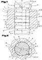
- Fig. 1 3 shows a longitudinal section through a die tool 1 for surface compacting a sintered part 2 by moving it along an axis 3 through the die tool 1.
- This comprises a tool main body 4 which has a first die opening 6 on a tool surface 5, of which several die sections 7 along the axis 3 , 8 and 9 lead into the interior of the tool base 4.
- a first die section 7 adjoins the first die opening 6
- a last die section 9 extends in the illustrated embodiment to an opposing second tool surface 10 and thereby forms a second die opening 11.
- the last die section 9 also in the interior of the tool base 4 end, whereby no second die opening 11 is formed.
- the sintered part 2 must in any case be removed again from the die tool 1 through the first die opening 6.
- the sintered part 2 consists of pressed and subsequently sintered powder metal, the methods and materials for producing such a sintered blank from the prior art are sufficiently known and therefore not further explained.
- the sintered part 2 is designed disc-shaped in the illustrated embodiment and has on an outer surface 12 has a diameter 13, which corresponds to a raw diameter 14 before the surface compression and after the surface compression corresponds to a smaller final diameter 15.
- the surface compacting of the sintered part 2 is carried out by being introduced through the first die opening 6 in the first die section 7 and subsequently in all other die sections 8 and also to the last die section 9, wherein in each die section 7, 8, 9, the outer surface 12 of the sintered part 2 at least on portions of the outer surface 12 against wall surfaces 16 of the die sections 7, 8, 9 is pressed.
- the contact surface 17 may thus by a part of the outer surface 12 or through the entire outer surface 12 may be formed;
- the pressing surface 18 may be formed by a portion of the wall surface 16 or even by the entire wall surface 16, wherein the portion may relate to the axial extent and / or on the extent in the circumferential direction.
- the pressing effect is achieved by an inner diameter 19, which is defined by the clear width between opposing or cooperating sections of the pressing surface 18 of a die section 7, 8, 9, being smaller than the raw diameter 14 of the sintered part 2.
- the term inner diameter 19 is not limited to circular cross-sections to understand, but also as a clear width between co-operating press surface parts that do not necessarily have to go through the axis 3 of the die tool 1.
- the diameter 13 on the sintered part 2 is not limited to radial directions.
- the successive die sections 7, 8, 9 along the axis 3 merge into one another continuously and have from the first die section 7 to the last die section 9 monotonically decreasing inner diameter 19, ie successive inner diameter 19 may be equal or decrease, but not larger ,
- a pressing direction 20 is defined, which is defined by the first Matrizenabêt 7 to the last die section 9 has.
- the movement of the sintered part 2 in the die tool 1 takes place in a straight line in the pressing direction 20 from the first die opening 6 to the last die section 9, followed by removal of the sintered part 2 from the die tool 1 via the second die opening 11 or reversing the direction of movement Pressing direction 20 through the first die opening 6.
- the rectilinear movement in the direction of the axis 3 can also be a rotational movement, e.g. in a rotational direction 21, be superimposed, whereby the sintered part 2 performs a screwing in the die 1.
- sintered parts 2 can also be compacted on their surface with the die workpiece 1, the outer surface 12 of which also comprises screwed surfaces.
- the movement of the sintered part 2 in this case takes place about a screw axis 22 which coincides or is parallel to the axis 3, for example if the screw surface to be compacted on the outer surface 12 of the sintered part 2 is not disposed on the entire circumference of the sintered part 2 and this does not have a rotationally symmetrical basic body.
- the direction of movement of the sintered part 2 in the die tool 1 can, as well as the speed of movement for optimizing the surface compaction, have an arbitrary course and, for example, also include a reversal of the direction of movement, a stoppage of movement, very slow but also very fast movements. Due to the interference fit, which is effective between the contact surfaces 17 and the pressing surfaces 18, compressive stresses, which are oriented substantially perpendicular to the contact surfaces 17, by the movement of the sintered part experiences the contact surface 17 in addition also a sliding friction stress in the axial direction with rectilinear motion or both in the axial and tangential direction in a screwing movement.
- the axial length of the sintered part 2 or the length of its contact surfaces 17 and the axial lengths of the die sections 7, 8, 9 Fig. 1 may be shorter than the contact surface length 24 of the die Sintered parts 2. It is even possible that the contact surface length 24 is greater than the sum of all die sections 7, 8, 9th
- the relative movement between the sintered part 2 and the die tool 1 required for carrying out the method can be effected by moving the sintered part 2 and / or by moving the die tool 1, wherein the sintered part 2 and the die tool 1 are each connected to a suitable drive or a fixed frame ,
- the sintered part 2 leaves the last die section 9 either through the second die opening 11 or after reversal of the direction of movement against the pressing direction 20 through the first die opening 6.
- the elastic deformations of the sintered part 2 which occur during the pressing in may thereby at least partially degrade and the diameter 13 of the sintered part 2 rises from the inner diameter 19 of the last Matrizenabitess 9 by the elastic spring back slightly on the larger end diameter 15, which corresponds as possible to the nominal diameter of the sintered part 2.
- Fig. 1 this is shown with a sintered part 2 shown in dashed lines, which is located in the pressing direction 20 after the last die section 9 and the end diameter 15 is slightly larger than the inner diameter 19 of the last die section.
- Fig. 2 shows a cross section according to the lines II-II in Fig. 1 This is in the illustrated embodiment, not rotationally symmetrical with respect to the axis 3, further extends its contact surface 17, takes place on the surface compression, not over its entire outer circumference, ie that only a portion of its outer surface 12 compacts becomes.
- the stencil tool 1 does not involve the entire wall surface 16 at the compression, but only the pressing surfaces 18, which contact the corresponding contact surfaces 17 of the sintered part 2. It can be seen that in the most general case the compaction of the surface takes place only where an inner contour 25 of a die section 7, 8, 9 defined by the wall surface 16 cooperates with an outer contour 26 defined by the outer surface 12 of the sintered part 2.
- a contact surface 17 on the sintered part 2 can be compressed in all die sections 7, 8, 9 by a corresponding pressing surface 18, but it is also possible that in individual or multiple die sections 7, 8 and or 9 only individual contact surfaces 7 or parts be compacted by the pressing surfaces 18 in single or more die sections 7, 8, 9 are made smaller.
- diameter 13 are considered in the context of the invention, which also extend through the axis 3, but also diameter 13, which correspond to a tooth thickness 27 on an outer toothing of the sintered part 2. Also in this case, opposite contact surfaces 17 of the sintered part 2 are pressed and compacted by opposing pressing surfaces 18 of a die section 7, 8, 9 by monotonically decreasing inner diameter 19.
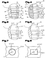
- Fig. 3 shows a section of a longitudinal section through an embodiment of the die tool 1 with four die sections 7, 8, 9, the inner diameter 19 in the pressing direction 20 are gradually smaller.
- the transition from a die section 7, 8 to the adjoining die section 8, 9 can be designed as a chamfer 28, or be provided with a rounding 29, wherein in the pressing direction 20 can connect to a concave curve convex rounding.
- a smooth transition of the sintered part 2 from one die section 7, 8 to the subsequent die section 8, 9 can take place without an unintentional material removal at the sintered part 2 being effected by a sheep-edged step, or the edges breaking off at the transitions of the die tool 1.
- Fig. 4 shows a section of a longitudinal section through an embodiment of the die tool 1, which is not in one piece in this embodiment, but is composed of a plurality of die plates 30. Notwithstanding the execution according to Fig. 3 in which the inner diameters 19 within the die sections 7, 8, 9 are respectively constant, ie are formed by a circular cylindrical surface 31, the die tool 1 has according to FIG Fig. 4 between each two die sections 7 and 8, 8 and 8, or 8 and 9 with circular cylindrical surfaces 31 and a die section 8, which has a cross-sectional taper 32 in the pressing direction 20.
- Fig. 5 1 shows a section from a longitudinal section through a further embodiment of the die tool 1.
- a die section 8 which is arranged between two further die sections 7 and 8, or 8 and 8, or 8 and 9 with circular cylinder surfaces 31, has a tapering surface 35, which has a progressive course in the pressing direction 20, ie the decrease of the inner diameter 19 within the die section 8 in the pressing direction 20 becomes stronger or increases.
- the decrease in the inner diameter 19 is progressive in the region of the taper surface 35.
- Fig. 6 shows a section of a longitudinal section through a further embodiment of the Matrizenwerkmaschines 1, wherein arranged between two Matrizenabitesen 7 and 8, or 8 and 8, or 8 and 9 with a circular cylindrical surface 31 as a wall surface 16, a die section 8 with a tapering surface 35 as a wall surface 16 is, in which the decrease in the inner diameter 19 in the pressing direction is lower, so has a degressive course.
- Fig. 7 shows a plan view of a further embodiment of the die tool 1, in which the inner contour 25 of the wall surface 16 is rotationally symmetrical with respect to the axis 3.
- Fig. 8 1 shows a plan view of a further embodiment of the die tool 1, in which the inner contour 25 of the wall surface 16 of the die sections 7, 8, 9 is rectangular performs.
- the inner contour 25 is therefore only rotationally symmetrical with respect to the axis 3 and suitable for compacting sintered parts with a rectangular cross-section.
- Fig. 9 a plan view of another embodiment of the die tool 1 with an inner contour 25 of the wall surfaces 16 of the die sections 7, 8, 9 which is composed of a circular section, a straight and a toothing.
- the method for compacting the surface of sintered parts 2 is thus not applicable to rotationally symmetrical or rotationally symmetrical outer contours 26 of sintered parts 2, but also for arbitrarily shaped outer contours 26.
- Fig. 10 shows a plan view of a further embodiment of the die tool 1, in which the inner contour 25 of the wall surfaces 16 of the die sections 7, 8, 9 form an internal toothing 36 with which the outer surfaces 12 of a gear can be compressed.
- the inner contour 25 can thereby run straight in the direction of the axis 3, whereby the Matrizenwerkmaschine 1 is suitable for surface compression of straight-toothed gears, the inner contour 25 is in the tool interior, however, not rectilinear, but continues with an additional screwing in the direction of rotation 21, with the die tool 1 gear wheels with helical teeth are surface-compressed.
- the wall surfaces 16 in inner contours 25 of the wall surfaces 16, according to the embodiments Fig. 8 and Fig. 9 follow a screwing movement, and compress the formed as a screw surfaces wall surfaces 16 of the die 1 according to cooperating as cooperating screw surfaces shaped contact surfaces 17 of an axially twisted, helical sintered part 2.
- Fig. 11 shows a longitudinal section through a further embodiment of the die tool 1, which has only a first die opening 6 and a sintered part 2 is therefore removed again after reaching the last die section 9 through the first die opening 6 from the die tool 1.
- the pressing surfaces 18 of the individual die sections 7 go in this embodiment with linear decreasing inner diameter 19 steplessly into one another. As a result, the individual die sections 7 merge into a single large die section.
- This embodiment of the die tool 1 can also be used to influence the final diameter 15 of the sintered part 2, by the sintered part 2 is used with different depth of immersion 37 in the die tool 1.
- sintered parts 2 can be surface-compacted with this embodiment of the die tool 1, in which it is not the maintenance of a specific final diameter 15 that is the focus, but the degree of surface compression. If, for example, a constant maximum force is always expended for the movement of the sintered part 2 in the pressing direction 20, in each case approximately the same surface compaction is achieved even when the raw diameters 14 of the sintered parts 2 fluctuate.
- Fig. 12 shows a longitudinal section through a further embodiment of the die tool 1, in which the individual die sections 7, 8, 9 are also fused to a single die section.
- Whose wall surface 16 and the pressing surface 18 is formed by a general tapering surface 35, the inner diameter 19 decreases degressively in the pressing direction 20 and expires with a circular cylindrical surface 31 in the region of the second die opening 11.
- Fig. 13 shows the implementation of the method according to the invention, in which two sintered parts 2 are pressed by means of a pressed against an end face 38 of a sintered part 2 pressure element 39, for example a ram in the pressing direction 20 by the die 1. Between the two sintered parts 2, a pressure-resistant spacer element 56 is arranged.
- the pressure element 39 is for this purpose connected to a suitable drive device 40, for example with a hydraulic press, a pneumatic press, a mechanical press, etc.
- Fig. 14 shows the implementation of the method in which a sintered part 2 is pulled in the pressing direction 20 by the die tool 1.
- a tension element 41 is fastened with a suitable anchoring 42, for example by screwing in the tension element 41, which in turn is connected to a suitable drive device 40.
- the implementation of the method with pushing through the sintered part 2 by the die 1 is particularly recommended for sintered parts 2, the axial length, in particular the contact surface length 24, is small, compared to the diameter 13, while the process variant with the pulling of the sintered part 2 by the die tool 1 can be used for sintered parts 2, whose axial length is greater than the diameter 13 of its cross section.
- Fig. 15 shows a further variant of the method for surface compaction, in which the sintered part 2 during the entire compression process at its two opposite end faces 38 between two pressure elements 39 with compressive forces 43 - indicated by small arrows - is acted upon. Both in a movement in the pressing direction 20, as well as in a movement in an opposite direction 44 - indicated by a dashed arrow.
- a reversal of the direction of movement can also be carried out in the case of disc-shaped sintered parts 2 with a small axial length, for example in order to enable intermediate relief and a reduction of elastic deformation.
- Fig. 16 1 shows a die tool 45, which has a die tool 1, an additional insertion section 46, which is arranged in the pressing direction 20 in front of the first die opening 6 of the die tool 1 and comprises an additional calibration section 47 which, viewed in the pressing direction 20, faces the second die opening 11 of the die tool 1 is arranged.
- the insertion section 46 is formed by an insertion plate 48, which is directly adjacent to the first tool surface 5 of the die tool 1.
- the insertion plate 48 is arranged coaxially with the die tool insertion opening 49, the wall surface 16, the same inner contour 25, as the die sections 7, 8, 9, but has an insertion diameter 50 which is greater than the raw diameter 14 of the sintered part. 2
- the insertion section 46 thus facilitates the accurate and positionally correct feeding of the sintered part 2 into the first die section 7 of the die tool 1.
- the calibration section 47 comprises a calibration plate 51 abutting the second, opposite tool surface 10, which has a calibration opening 52 coaxial with the die tool 1, the wall surface 16 of which has the same inner contour 25 as the matrix tool 1, but has a calibration diameter 53 corresponding to the nominal diameter of the sintered part 2 corresponds or is smaller. After the last die section whose diameter 19 is smaller than the nominal diameter of the finished sintered part 2, this can extend in the calibration section 47 up to the calibration diameter 53, ie the nominal diameter, whereby the final diameter 15 at least approximately corresponds to the nominal diameter.
- a relief section 54 can be connected directly to the second die opening 11, which has a relief diameter 55 which is greater than the nominal diameter or The end diameter 15 of the sintered part 2.
- the calibration stage can be longer in the direction of the axis 3 than the overall height of the sintered part in this direction. Furthermore, the calibration stage can alseisen a larger diameter than the last die section 9, whereby in the ejection of the sintered part 2 on the first die opening 6 in turn a kneading effect is achieved.
Landscapes
- Engineering & Computer Science (AREA)
- Manufacturing & Machinery (AREA)
- Mechanical Engineering (AREA)
- Powder Metallurgy (AREA)
Description
Die Erfindung betrifft ein Verfahren zur Oberflächenverdichtung von Sinterteilen mit den Merkmalen des Anspruches 1.The invention relates to a method for surface compacting of sintered parts with the features of
Sinterteile, also Werkstücke aus gepresstem und gesintertem Metallpulver sind schon seit Längerem eine Alternative zu gegossenen oder aus den vollen bearbeiteten Werkstücken. Die durch das Herstellverfahren bedingte, jeweils mehr oder weniger stark ausgeprägte Porosität der Sinterteile wirkt sich jedoch negativ auf die Biegefestigkeit und die Verschleißfestigkeit aus, was beispielsweise den Einsatz von pulvermetallurgisch hergestellten Zahnrädern in hoch belasteten Getrieben einschränkt.Sintered parts, ie workpieces made of pressed and sintered metal powder have long been an alternative to cast or from the fully machined workpieces. However, due to the manufacturing process, in each case more or less pronounced porosity of the sintered parts has a negative effect on the flexural strength and the wear resistance, which limits, for example, the use of powder-metallurgically produced gears in high-load gearboxes.
Um die nachteiligen Auswirkungen der Porosität von Sinterteilen zu reduzieren, ist es bekannt, an Sinterteilrohlingen durch Nachpressen eine Oberflächenverdichtung zu bewirken. Ein Verfahren, das dazu ein Matrizenwerkzeug verwendet, ist aus der
Diese Druck-Eigenspannungen erhöhen die Biegefestigkeit in zugbeanspruchten Zonen und verbessern gleichzeitig die Verschleißfestigkeit der derart verdichteten Oberfläche. Nachteilig bei dem in der US-B1 beschriebenen Verfahren bzw. Matrizenwerkzeug ist jedoch, dass das Matrizenwerkzeug aufgrund der zwischen den einzelnen Matrizenplatten ausgeführten Zwischenräume eine geringere Stabilität und Verschleißfestigkeit aufweist, wodurch die vom Matrizenwerkzeug ertragbaren Umformkräfte deutlich begrenzt sind und die erzielbare Oberflächenverdichtung für gewisse Anwendungen noch unzureichend ist.These compressive residual stresses increase the bending strength in tensile stressed zones and at the same time improve the wear resistance of the surface thus compacted. adversely However, in the method or die tool described in US-B1, the die tool has a lower stability and wear resistance due to the spaces between the die plates, which significantly limits the forming forces that can be borne by the die tool, and the achievable surface densification for certain applications is insufficient.
Aus der
Die
Aus der
Die
Aufgabe der Erfindung ist es ein Verfahren zur Oberflächenverdichtung eines Sinterteils bereitzustellen, das die Möglichkeit einer hohen Verdichtung einer Sinterteiloberfläche bei gleichzeitig einfachem Werkzeugaufbau bietet.The object of the invention is to provide a method for surface compacting a sintered part, which offers the possibility of a high compression of a sintered part surface while at the same time a simple tool design.
Diese Aufgabe wird durch ein Verfahren zur Oberflächenverdichtung von Sinterteilen mit den Merkmalen des unabhängigen Anspruchs 1 gelöst. Dadurch, dass die Matrizenabschnitte stetig ineinander übergehen und ein zwischen zusammenwirkenden Pressflächenteilen gemessener Innendurchmesser an der Innenkontur vom ersten Matrizenabschnitt bis zum letzten Matrizenabschnitt monoton abnimmt, wird bei der Bewegung eines Sinterteils in Pressrichtung bis auf den letzten Matrizenabschnitt jeder Matrizenabschnitt vom nachfolgenden gestützt und Verformungen des Matrizenwerkzeugs weitgehend verhindert. Durch diese robuste Bauweise des Matrizenwerkzeuges kann die insgesamte Reduktion der Innendurchmesser stärker ausgeführt werden, wodurch die Oberflächenverdichtung des Sinterteils deutlich verbessert wird. Ein überraschender Effekt an dieser Ausbildung ist, dass auch ohne die aus dem Stand der Technik bekannte Zwischenentlastung zwischen aufeinander folgenden Matrizenabschnitten die Oberflächen der Sinterteile ohne negative Auswirkungen der hohen Umformkräfte, wie z.B. Fresserscheinungen, verdichtet werden können.This object is achieved by a method for surface compacting sintered parts having the features of
Die Verdichtung der Oberfläche muss dabei nicht am gesamten Außenumfang eines Sinterteils erfolgen, sondern kann sich auf Teilabschnitte der Außenfläche beschränken. Für die Durchführung des Verfahrens ist dabei lediglich erforderlich, dass die auf die Kontaktflächen am Sinterteil wirkenden Pressflächen etwa gegenüberliegend angeordnet sind, um die radial wirkenden Kräfte ausgleichen zu können. Der Begriff Innendurchmesser ist in dieser Anmeldung nicht eingeschränkt auf den Durchmesser eines Zylinders zu verstehen, sondern allgemein als zwischen zusammenwirkenden Pressflächen gemessene Weite zwischen einander zugewandten Pressflächenteilen.The compaction of the surface does not have to take place on the entire outer circumference of a sintered part, but can be limited to subsections of the outer surface. For carrying out the method, it is merely necessary for the pressing surfaces acting on the contact surfaces on the sintered part to be arranged approximately opposite one another in order to be able to compensate for the radially acting forces. The term inner diameter in this application is not limited to the diameter of a cylinder, but is generally understood to mean the distance between facing press surfaces as measured between cooperating pressing surfaces.
Der Innendurchmesser innerhalb eines Matrizenabschnitts verläuft konstant, d.h. dass sich der Matrizenabschnitt nicht verjüngt. Im Fall einer rotationssymmetrischen Kontaktfläche am Sinterteil ist die auf diese einwirkende Pressfläche des Matrizenabschnitts eine kreiszylindrische Fläche mit zur Achse parallelen erzeugenden. Da ein kreiszylindrischer Matrizenabschnitt relativ einfach herzustellen ist, kann ein Matrizenwerkzeug für kreiszylindrische Sinterteile mit einfachen Mitteln hergestellt werden, wenn alle Matrizenabschnitte jeweils konstante Innendurchmesser aufweisen.The inner diameter within a die section is constant, i. that the die section does not taper. In the case of a rotationally symmetrical contact surface on the sintered part, the pressing surface of the die section acting on it is a circular-cylindrical surface with generatrixes parallel to the axis. Since a circular cylindrical die portion is relatively easy to manufacture, a die tool for circular cylindrical sintered parts can be produced by simple means, when all die sections each have constant inner diameters.
Der Übergang von einem Matrizenabschnitt zu einem nachfolgenden Matrizenabschnitt ist mit zumindest einer Rundung ausgebildet, wobei in der Pressrichtung an eine konkave Rundung eine konvexe Rundung anschließt. Eine scharfkantige Ausbildung eines stufenartigen Überganges und ein dementsprechend höherer Verschleiß am Matrizenwerkzeug kann dadurch weitestgehend vermieden werden.The transition from a die section to a subsequent die section is formed with at least one rounding, wherein in the pressing direction to a concave curve connects a convex curve. A sharp-edged design of a stepped transition and a correspondingly higher wear on the die tool can be largely avoided.
Bei einem Matrizenwerkzeug, bei dem der letzte Matrizenabschnitt im Inneren des Werkzeugkörpers endet, muss der Sinterteil nach Bewegungsumkehr durch die erste Matrizenöffnung aus dem Matrizenwerkzeug entnommen werden, das Verfahren kann jedoch vorteilhaft ergänzt werden, indem der Sinterteil durch eine der ersten Matrizenöffnung gegenüberliegende zweite Matrizenöffnung aus dem Matrizenwerkzeug bewegt wird.In a die tool in which the last die section terminates inside the tool body, the sintered part must be removed after reversing the motion through the first die opening from the die tool, but the method can be advantageously supplemented by the sintered part by a second die opening opposite the first die opening the die tool is moved.
Die Relativbewegung zwischen Sinterteil und Matrizenwerkzeug kann dabei vorteilhaft geradlinig oder in einer Schraubbewegung erfolgen. Sinterteile, deren Kontaktflächen rotationssymmetrisch bezüglich der Achse sind, können sowohl geradlinig als auch mit einer Schraubbewegung oder einer Kombination daraus durch das Matrizenwerkzeug gedrückt werden, Sinterteile, deren Kontaktflächen durch Schraubflächen gebildet sind, müssen in einer Schraubbewegung durch das Matrizenwerkzeug gedrückt werden. Bei einem rotationssymmetrischen Sinterteil, können zusätzlich zu den axial wirkenden Gleitreibungskräften an den Pressflächen der Matrizenabschnitte durch eine drehende Bewegung zusätzlich tangentiale Spannungskomponenten in die Oberfläche des Sinterteils eingeleitet werden, was den Verdichtungsvorgang günstig beeinflussen kann.The relative movement between the sintered part and the die tool can advantageously be rectilinear or in a screwing motion. Sintered parts whose contact surfaces are rotationally symmetrical with respect to the axis can be pressed both rectilinearly and with a screwing motion or a combination thereof through the die tool. Sintered parts whose contact surfaces are formed by screw surfaces must be pressed in a screwing motion by the die tool. In the case of a rotationally symmetrical sintered part, in addition to the axially acting sliding friction forces on the pressing faces of the die sections, additional tangential stress components can be introduced into the surface of the sintered part by a rotating movement, which can favorably influence the compacting process.
Für die Durchführung des Verfahrens kann es auch von Vorteil sein, wenn die Bewegung vom Sinterteil und/oder vom Matrizenwerkzeug ausgeführt wird. Im einfachsten Fall wird bei feststehendem Matrizenwerkzeug der Sinterteil vom ersten Matrizenabschnitt bis zum letzten Matrizenabschnitt bewegt, es kann jedoch aus baulichen Gründen oder aus Verfahrensgründen vorteilhaft sein, die Bewegung vom Matrizenwerkzeug ausführen zu lassen oder sowohl den Sinterteil als auch das Matrizenwerkzeug anzutreiben. Dabei können gleiche Antriebskonzepte aber auch unterschiedliche Antriebskonzepte für die beiden Bestandteile eingesetzt werden, z.B. indem der Sinterteil oder das Matrizenwerkzeug eine gleichmäßige langsame Bewegung ausführt, und das Matrizenwerkzeug bzw. der Sinterteil eine intermittierende schnelle Bewegung ausführt, wodurch sich eine pulsierende Relativgeschwindigkeit ergibt, was von Vorteil sein kann, wenn ein Stillstand der Relativbewegung unerwünscht ist und die Bewegung von einem Matrizenabschnitt zum nachfolgenden Abschnitt mit höherer Geschwindigkeit ausgeführt werden soll.For carrying out the method, it can also be advantageous if the movement is carried out by the sintered part and / or the die tool. In the simplest case, with a fixed die tool, the sintered part is moved from the first die section to the last die section, but it can be advantageous for structural reasons or for procedural reasons to let the movement be performed by the die tool or to drive both the sintered part and the die tool. In this case, the same drive concepts but also different drive concepts for the two components can be used, e.g. in that the sintered part or the die tool performs a smooth, slow movement, and the die tool or die performs an intermittent fast movement, resulting in a pulsating relative speed, which may be advantageous when a relative movement stop is undesirable and the movement from one Matrizenabschnitt to the subsequent section with higher speed to be executed.
Bei der Bewegung durch das Matrizenwerkzeug kann der Sinterteil dabei sowohl in Achsrichtung gedrückt als auch gezogen werden, wobei die Einleitung entsprechend hoher Zugkräfte bei in axialer Richtung geringen Abmessungen des Sinterteils aufgrund der Bruchgefahr zu vermeiden ist und auf Sinterteile mit axial größeren Abmessungen beschränkt bleiben sollte.During the movement through the die tool, the sintered part can be pressed and pulled both in the axial direction, and the introduction of correspondingly high tensile forces should be avoided in the axial direction of small dimensions of the sintered part due to the risk of breakage and should remain limited to sintered parts with axially larger dimensions.
Eine optimale Einleitung der erforderlichen Kräfte in den Sinterteil erzielt man, wenn der Sinterteil zwischen zwei Druckelementen, z.B. zwei mit Antriebseinrichtungen verbundenen Stempeln, weitgehend vollflächig axial druckbeaufschlagt wird. Dadurch kann die Bewegung durch das Matrizenwerkzeug auch mit einer Richtungsumkehr ausgeführt werden, ohne dass die Gefahr besteht, dass der Sinterteil durch das Auftreten von höheren Zugspannungen Schaden nimmt. Der Sinterteil kann dazu zwischen zwei Druckstempeln, deren Form im Wesentlichen der Matrizenform entspricht, eingespannt sein.Optimum introduction of the required forces into the sintered part is achieved when the sintered part is placed between two pressure elements, e.g. two stamping associated with drive means, is largely pressurized over the entire surface axially. As a result, the movement through the die tool can also be carried out with a reversal of the direction without the risk of the sintered part being damaged by the occurrence of higher tensile stresses. For this purpose, the sintered part can be clamped between two pressure punches whose shape substantially corresponds to the matrix shape.
Für die Durchführung des Verfahrens kann es günstig sein, die Bewegungsrichtung des Sinterteils vor Erreichen der zweiten Matrizenöffnung zumindest einmal zu ändern, beispielsweise um bei einem empfindlicheren Sinterwerkstoff eine Zwischenentlastung vor dem Bewegen in oder durch den letzten Matrizenabschnitt zu ermöglichen.For carrying out the method, it may be favorable to change the direction of movement of the sintered part at least once before reaching the second die opening, for example to enable intermediate relief in a more sensitive sintered material before moving into or through the last die section.
Eine vorteilhafte Variante des Verfahrens kann auch darin bestehen, dass der Sinterteil nach Erreichen des letzten Matrizenabschnitts durch die erste Matrizenöffnung aus dem Werkzeug entformt wird, d.h. die Bewegungsrichtung nach dem Erreichen des letzten Matrizenabschnitts umgekehrt wird. Dadurch, dass die Teileabfuhr auf den Matrizenwerkzeug an derselben Position wie die Teilezufuhr vor der Verfahrensdurchführung erfolgt, kann diese Variante vorteilhaft für den Teilefluss sein.An advantageous variant of the method can also be that the sintered part is removed from the mold after reaching the last die section through the first die opening, i. the direction of movement is reversed after reaching the last die section. Due to the fact that the part removal onto the die tool takes place at the same position as the parts feed before the process is carried out, this variant can be advantageous for the part flow.
Da der letzte Matrizenabschnitt Einfluss auf das nach der Verfahrensdurchführung erzielte Fertigmaß des Sinterteils hat, ist es von Vorteil, wenn der Sinterteil im letzten Matrizenabschnitt auf einen Innendurchmesser komprimiert wird, der einem Sollmaß eines Sinterteils verringert um den Wert der aufgrund der Presskräfte bewirkten elastischen Verformung des Sinterteils an diesem Innendurchmesser entspricht. Da die plastische Verformung im Wesentlichen an der äußeren Oberfläche des Sinterteils erfolgt, kann der elastische Anteil der Verformung durch Rechenverfahren verhältnismäßig gut abgeschätzt werden, weshalb es dadurch möglich ist, den letzten Matrizenabschnitt derart auszubilden, dass der Sinterteil nach Entformung des letzten Matrizenabschnitts im Wesentlichen sein Sollmaß aufweist. Die dadurch erreichte Maßgenauigkeit kann nachfolgende Bearbeitungsschritte zur weiteren Annäherung des Fertigmaßes an ein Sollmaß, z.B. einen Schleifvorgang, entbehrlich machen.Since the last die section has an influence on the finished size of the sintered part achieved after the process, it is advantageous if the sintered part in the last die section is compressed to an inner diameter which reduces a nominal dimension of a sintered part by the value of the elastic deformation of the sintered part caused by the pressing forces Sintered parts corresponds to this inner diameter. Since the plastic deformation takes place substantially on the outer surface of the sintered body, the elastic portion of the deformation can be estimated relatively well by calculation methods, and therefore it is possible to form the last die portion such that the sintered body after being removed from the last die portion substantially Has nominal size. The dimensional accuracy achieved thereby can subsequent processing steps for further approximation the finished measure to a nominal size, eg make a grinding process unnecessary.
Zur Erleichterung des Einbringens des Sinterteils in das Matrizenwerkzeug, ist es günstig, wenn der Sinterteil in einen vor der ersten Matrizenöffnung angeordneten Einführabschnitt eingebracht wird, der einen Einführdurchmesser aufweist, der größer ist, als eine Rohabmessung des Sinterteils an seiner Außenfläche. Dieser Einführabschnitt kann z.B. durch eine zusätzliche Einführplatte, die in Pressrichtung vor dem ersten Matrizenabschnitt angeordnet ist, gebildet sein und weist eine Öffnung auf, die um ein kleines Funktionsspiel größer ist, als die Rohabmessungen des Sinterteils an seiner Außenfläche. Dadurch erfolgt eine zuverlässige Positionierung sowie eine Führung des Sinterteils vor und während des Einpressens in den ersten Matrizenabschnitt.In order to facilitate the introduction of the sintered part into the die tool, it is favorable if the sintered part is introduced into an insertion section arranged in front of the first die opening, which has an insertion diameter which is greater than a rough measurement of the sintered part on its outer surface. This insertion section may e.g. be formed by an additional insertion plate, which is arranged in the pressing direction before the first die portion, and has an opening which is larger by a small functional clearance, as the Rohabmessungen the sintered part on its outer surface. This results in reliable positioning and guidance of the sintered part before and during the pressing into the first die section.
Ebenfalls von Vorteil ist es, wenn der Sinterteil nach dem letzten Matrizenabschnitt in einen daran anschließenden Kalibrierabschnitt bewegt wird, der einen Kalibrierdurchmesser aufweist, der einem Solldurchmesser des Sinterteils an seiner Außenfläche entspricht. Der Kalibrierabschnitt kann dabei unmittelbar an den letzten Matrizenabschnitt anschließen, oder aber auch mit einem Zwischenraum zwischen dem letzten Matrizenabschnitt und dem maßhaltigen Kalibrierabschnitt versehen sein, wodurch vor der Kalibrierung eine Zwischenentlastung des Sinterteils möglich ist.It is also advantageous if the sintered part is moved after the last die section into a subsequent calibration section, which has a calibration diameter corresponding to a desired diameter of the sintered part on its outer surface. In this case, the calibration section can connect directly to the last die section, or it can also be provided with a gap between the last die section and the dimensional calibration section, whereby an intermediate relief of the sintered part is possible before the calibration.
Eine mögliche Ausführung des Verfahrens besteht darin, dass eine Folge von Sinterteilen mit oder ohne jeweils zwischen zwei Sinterteilen angeordneten, druckfesten Distanzelementen durch das Matrizenwerkzeug bewegt wird.A possible embodiment of the method consists in that a sequence of sintered parts with or without pressure-resistant spacer elements each arranged between two sintered parts is moved by the die tool.
Während im einfachsten Fall das Verfahren etwa bei Raumtemperatur durchgeführt wird, kann es von Vorteil sein, wenn der Sinterteil bei der Verfahrensdurchführung eine Temperatur aufweist, die unterhalb der Schmelztemperatur, insbesondere in einem Bereich von 100 °C bzw. 200 °C unter der Schmelztemperatur, liegt. Durch die gegenüber der Raumtemperatur erhöhte Temperatur bei der Verfahrensausführung kann der Vorgang der Oberflächenverdichtung und die dabei ablaufende Änderung des Gefüges erleichtert werden, wodurch einerseits die Oberflächeneigenschaften des fertigen Sinterteils vorteilhaft beeinflusst werden können und die für die Verfahrensdurchführung erforderlichen Kräfte reduziert sein können.While in the simplest case the method is carried out approximately at room temperature, it may be advantageous if the sintered part has a temperature below the melting temperature, in particular in a range of 100 ° C. or 200 ° C. below the melting temperature, during the process. lies. Due to the increased temperature compared to the room temperature in the process execution of the process of surface compaction and thereby occurring change of the structure can be facilitated, which on the one hand, the surface properties of the finished sintered part can be favorably influenced and the forces required for the process performance can be reduced.
Die Anwendung des Verfahrens ist insbesondere von Vorteil, wenn der Sinterteil als Lagerbuchse, als Lagerschale, als Zahnrad, als Kettenrad, als Zahnriemenrad oder als Nockenelement ausgeführt ist. Die mit dem Verfahren erzielbare Oberflächenverdichtung und Erhöhung der Biegefestigkeit erweist sich bei diesen Anwendungen eines Sinterteils als besonders vorteilhaft.The application of the method is particularly advantageous if the sintered part is designed as a bearing bush, as a bearing shell, as a gear wheel, as a sprocket, as a toothed belt wheel or as a cam element. The achievable with the method surface compaction and increasing the bending strength proves to be particularly advantageous in these applications of a sintered part.
Vorteilhaft für die Verwendung des Matrizenwerkzeugs kann es sein, wenn an den letzten Matrizenabschnitt eine zur ersten Matrizenöffnung gegenüberliegende zweite Matrizenöffnung anschließt, d.h. der Sinterteil durch das gesamte Matrizenwerkzeug hindurch bewegt, insbesondere gepresst werden kann.It may be advantageous for the use of the die tool if a second die opening opposite the first die opening adjoins the last die section, i. the sintered part can be moved through the entire die tool, in particular pressed.
Für die Durchführung des Verfahrens kann es sich auch als vorteilhaft erweisen, wenn eine axiale Matrizenabschnittslänge größer ist, als eine axiale Kontaktflächenlänge. Dadurch ist sichergestellt, dass ein Sinterteil bzw. dessen Kontaktfläche zur Gänze in einen Matrizenabschnitt eingeführt ist, bevor eine Vorderkante des Sinterteils bzw. der Kontaktfläche schon die Verformung durch den nachfolgenden Matrizenabschnitt erfährt. Die für die Bewegung des Sinterteils erforderliche Kraft ist dadurch fallweise weitgehend gleich bleibend, wodurch eine phasenweise, gleich bleibende Bewegungsgeschwindigkeit relativ einfach, z.B. über eine Drucksteuerung eines Fluidzylinders, der auf des Sinterteil wirkt, erzielbar ist.For carrying out the method, it may also prove advantageous if an axial die section length is greater than an axial contact face length. This ensures that a sintered part or its contact surface is wholly introduced into a die section before a leading edge of the sintered part or the contact surface already undergoes the deformation by the subsequent die section. The for the movement of the Sintered parts required force is thus occasionally largely constant, whereby a phase-wise, constant movement speed relatively easy, eg via a pressure control of a fluid cylinder which acts on the sintered part, can be achieved.
Die axiale Matrizenabschnittslänge des letzten Matrizenabschnitts kann weniger als 30 % der Kontaktflächenlänge des Sinterteils betragen. Ein derart relativ kurz ausgeführter letzter Matrizenabschnitt bewirkt einen auf einen kleinen Anteil der Kontaktfläche begrenzten Kneteffekt, der die Wirksamkeit der Oberflächenverdichtung zusätzlich erhöhen kann. Dabei kann dieser Matrizenabschnitt konisch ausgebildet sein, wodurch der Kneteffekt verstärkt wird. Insbesondere ist dies von Vorteil, wenn der Sinterteil wieder durch die erste Matrizenöffnung aus dem Matrizenwerkzeug entfernt wird.The axial die section length of the last die section may be less than 30% of the contact surface length of the sintered part. Such a relatively short executed Last Matrizenabschnitt causes a limited to a small proportion of the contact surface kneading effect, which can increase the effectiveness of surface compaction in addition. In this case, this Matrizenabschnitt be conical, whereby the kneading effect is enhanced. In particular, this is advantageous if the sintered part is removed again from the die tool through the first die opening.
Insbesondere bei Sinterteilen mit großer Länge ist es von Vorteil, wenn die axiale Länge aller Matrizenabschnitte in Summe kleiner ist, als die axiale Kontaktflächenlänge des Sinterteils. Dadurch erfolgt die Oberflächenverdichtung jeweils nur auf einem geringen Teil der Kontaktfläche und die Einflüsse der axialen Gleitreibung sind dadurch gegenüber einem längeren Werkzeug geringer.Particularly in the case of long-length sintered parts, it is advantageous if the total axial length of all die sections is smaller in total than the axial contact surface length of the sintered part. As a result, the surface compression takes place only on a small part of the contact surface and the influences of the axial sliding friction are thereby lower compared to a longer tool.
Für die Ausführung des Verfahrens ist es notwendig, insgesamt zwischen drei und sieben, insbesondere fünf, Matrizenabschnitte mit jeweils konstantem Innendurchmesser vorzusehen. Da die zunehmende Verdichtung der Randschicht auch eine Verfestigung bewirkt, die ähnlich einer festen Schale weiteren Verformungen zunehmenden Widerstand entgegensetzt, ist die mögliche Durchmesserreduktion begrenzt, wobei die Aufteilung auf die genannten Anzahlen an Matrizenabschnitten von Vorteil ist, da die Herstellungskosten für das Matrizenwerkzeug mit der Anzahl der Matrizenabschnitte zunehmen.For the execution of the method, it is necessary to provide a total of between three and seven, in particular five, die sections each having a constant inner diameter. Since the increasing densification of the surface layer also causes a solidification, which opposes further deformations increasingly resistance similar to a solid shell, the possible diameter reduction is limited, the division of said numbers of die sections is advantageous because the manufacturing costs for the die tool with the number increase the Matrizenabschnitte.
Um einen durch das Matrizenwerkzeug erreichbaren Istdurchmesser des Sinterteils möglichst an einen Solldurchmesser anzunähern, ist es von Vorteil, wen der Innendurchmesser im letzten Matrizenabschnitt einen Wert aufweist, der einem Sollmaß des Sinterteils verringert um den Wert, der aufgrund der Presskräfte bewirkten elastischen Verformung des Sinterteils an diesem Innendurchmesser entspricht. Wie bereits zuvor erläutert, kann die elastische Verformung des Sinterteils zu diesem Zweck mit hinreichend guter Genauigkeit abgeschätzt werden, wodurch der Sinterteil nach Passieren des letzten Matrizenabschnitts zumindest annähernd sein Sollmaß aufweist.In order to approximate an actual diameter of the sintered part achievable by the die tool to a target diameter, it is advantageous if the inner diameter in the last die section has a value which reduces a nominal dimension of the sintered part by the value of the elastic deformation of the sintered part due to the pressing forces this inner diameter corresponds. As already explained above, the elastic deformation of the sintered part can be estimated for this purpose with sufficiently good accuracy, whereby the sintered part after passing through the last die section has at least approximately its nominal dimension.
Für die Oberflächenverdichtung von kreiszylindrischen Sinterteilen, wie z.B. Lagerbuchsen, ist es von Vorteil, wenn die Innenkontur bezüglich der Achse rotationssymmetrisch ist. Dadurch kann die Oberfläche eines kreiszylindrischen Sinterteils mit einmaliger Verfahrensdurchführung an ihrem gesamten Umfang verdichtet werden, während bei nur teilweise als Kreiszylinder ausgeführten Pressflächen ein zwei- oder mehrmaliges Durchführen des Pressvorgangs mit dazwischen liegendem Verdrehen des Sinterteils erforderlich wäre.For the surface compaction of circular cylindrical sintered parts, such as e.g. Bushings, it is advantageous if the inner contour is rotationally symmetrical with respect to the axis. Thereby, the surface of a circular cylindrical sintered part can be compacted with a single process implementation over its entire circumference, while in only partially executed as a circular cylinder pressing surfaces a two or more times performing the pressing operation with intermediate rotation of the sintered part would be required.
Ebenfalls vorteilhaft ist, wenn die Innenkontur bezüglich der Achse drehsymmetrisch ist, wodurch das Matrizenwerkzeug, insbesondere auch für die Oberflächenverdichtung von gesinterten Zahnrädern, Zahnriemenrädern oder Kettenrädern anwendbar ist. Das Verfahren ist jedoch auch bei unregelmäßig geformten Sinterteilen anwendbar, wenn die Pressfläche eines Matrizenabschnitts als allgemeine Zylinderfläche gebildet ist. Die Anwendung ist somit nicht auf rotations- bzw. drehsymmetrische Sinterteile beschränkt.It is also advantageous if the inner contour is rotationally symmetrical with respect to the axis, whereby the die tool, in particular for the surface compression of sintered gears, toothed belt wheels or sprockets is applicable. However, the method is also applicable to irregularly shaped sintered parts, when the pressing surface of a Matrizenabschnitts is formed as a general cylindrical surface. The application is therefore not limited to rotational or rotationally symmetrical sintered parts.
Die Pressfläche eines Matrizenabschnitts kann auch durch eine Schraubfläche gebildet sein, wodurch auch die Oberflächen eines schräg verzahnten Zahnrades verdichtet werden kann, wenn die Bewegung durch das Matrizenwerkzeug mit einer Schraubbewegung durchgeführt wird.The pressing surface of a die portion can also be formed by a screw surface, whereby the surfaces of a helical gear can be compressed when the movement is performed by the die tool with a screwing movement.
Zur Verdichtung der Oberfläche eines geradverzahnten Stirnrades oder eines Stirnradsegments, sind die Pressflächen der Matrizenabschnitte jeweils zumindest abschnittsweise durch eine Innengeradverzahnung gebildet. Die Zahnflanken verlaufen dabei in axialer Richtung.For compacting the surface of a straight-toothed spur gear or a spur gear segment, the pressing surfaces of the die sections are each formed at least in sections by internal straight toothing. The tooth flanks extend in the axial direction.
Wenn die Pressflächen der Matrizenabschnitte jeweils zumindest abschnittsweise durch eine Innenschrägverzahnung gebildet sind, können auch schräg verzahnte Stirnräder oder Stirnradsegmente oberflächenverdichtet werden.If the pressing surfaces of the die sections are each formed, at least in sections, by internal helical gearing, helical spur gears or spur gear segments can also be surface-compacted.
Das Matrizenwerkzeug kann sowohl in axialer als auch in radialer Richtung aus mehreren Matrizenteilen zusammengesetzt sein, eine äußerst robuste Ausführung erzielt man jedoch, wenn das Matrizenwerkzeug einstückig ausgeführt ist.The die tool can be composed of several die parts both in the axial and in the radial direction, but an extremely robust design is achieved if the die tool is made in one piece.
Das Einführen eines Sinterteils in das Matrizenwerkzeug wird wesentlich erleichtert, wenn in Richtung zur zweiten Matrizenöffnung, vor dem ersten Matrizenabschnitt, ein Einführabschnitt, dessen Innendurchmesser größer ist, als ein Rohdurchmesser des Sinterteils, angeordnet ist. Der Einführabschnitt entspricht dabei einem Matrizenabschnitt, allerdings mit einer Spielpassung anstatt einer Presspassung zum Sinterteil.The introduction of a sintered part into the die tool is substantially facilitated if, in the direction of the second die opening, before the first die section, an insertion section whose inner diameter is larger than a raw diameter of the sintered part is arranged. The insertion section corresponds to a die section, but with a clearance fit instead of a press fit to the sintered part.
Zur Erhöhung der Maßgenauigkeit kann weiters vorgesehen sein, dass in Pressrichtung nach dem letzten Matrizenabschnitt ein Kalibrierabschnitt anschließt, der einen Kalibrierdurchmesser aufweist, der kleiner ist als der Solldurchmesser des Sinterteils. Dabei kann der Kalibrierabschnitt direkt an den letzten Matrizenabschnitt anschließen oder dazwischen ein Abstand vorgesehen sein, der eine Zwischenentlastung des Sinterteils bewirkt, der dadurch vor dem eigentlichen Kalibierabschnitt seine elastische Verformung durch Ausdehnung zumindest teilweise abbaut.To increase the dimensional accuracy can further be provided that in the pressing direction after the last die section followed by a Kalibrierabschnitt having a Kalibrierdurchmesser which is smaller than the nominal diameter of the sintered part. In this case, the calibration can connect directly to the last Matrizenabschnitt or be provided therebetween a distance which causes an intermediate relief of the sintered part, which thereby at least partially degrades its elastic deformation by expansion before the actual calibration section.
Die Erfindung wird im Nachfolgenden anhand der in den Zeichnungen dargestellten Ausführungsbeispiele näher erläutert.The invention will be explained in more detail below with reference to the embodiments illustrated in the drawings.
Es zeigen jeweils in vereinfachter schematischer Darstellung:
- Fig. 1
- einen Längsschnitt gemäß der Linie I-I in
Fig. 2 durch ein nicht erfindungsgemäßes Matrizenwerkzeug mit einem damit zu bearbeitenden Sinterteil; - Fig. 2
- einen Querschnitt durch ein nicht erfindungsgemäßes Matrizenwerkzeug mit einem damit bearbeiteten Sinterteil gemäß den Linien II-II in
Fig. 1 ; - Fig. 3
- einen Ausschnitt aus einem Längsschnitt einer Ausführungsform eines Matrizenwerkzeugs;
- Fig. 4
- einen Ausschnitt aus einem Längsschnitt eines nicht erfindungsgemäßen Matrizen werkzeugs;
- Fig. 5
- einen Ausschnitt aus einem Längsschnitt eines nicht erfindungsgemäßen Matrizenwerkzeugs;
- Fig. 6
- einen Ausschnitt aus einem Längsschnitt eines nicht erfindungsgemäßen Matrizenwerkzeugs;
- Fig. 7
- eine axiale Draufsicht auf eine weitere Ausführungsform des Matrizenwerkzeugs;
- Fig. 8
- eine Draufsicht auf eine weitere Ausführungsform des Matrizenwerkzeugs;
- Fig. 9
- eine Draufsicht auf eine weitere Ausführungsform des Matrizenwerkzeugs;
- Fig. 10
- eine Draufsicht auf zwei weitere Ausführungsformen des Matrizenwerkzeugs mit einer geraden sowie einer schrägen Innenverzahnung;
- Fig. 11
- einen Längsschnitt durch ein nicht erfindungsgemäßes Matrizenwerkzeug;
- Fig. 12
- einen Längsschnitt durch ein nicht erfindungsgemäßes Matrizenwerkzeug;
- Fig. 13
- die Durchführung des Verfahrens mit gleichzeitigem Durchdrücken von zwei Sinterteilen durch das Matrizenwerkzeug;
- Fig. 14
- das Verfahren mit Durchziehen des Sinterteils durch das Matrizenwerkzeug;
- Fig. 15
- die Verfahrensdurchführung mit beidseitig druckbeaufschlagbarem Sinterteil;
- Fig. 16
- ein nicht erfindungsgemäßes Matrizenwerkzeug mit einem zusätzlichen Einführabschnitt und einem zusätzlichen Kalibrierabschnitt.
- Fig. 1
- a longitudinal section along the line II in
Fig. 2 by a non-inventive die tool with a sintered part to be machined therewith; - Fig. 2
- a cross section through a non-inventive die tool with a processed sintered part according to the lines II-II in
Fig. 1 ; - Fig. 3
- a detail of a longitudinal section of an embodiment of a Matrizenwerkzeugs;
- Fig. 4
- a section of a longitudinal section of a non-inventive dies tool;
- Fig. 5
- a detail of a longitudinal section of a non-inventive die tool;
- Fig. 6
- a detail of a longitudinal section of a non-inventive die tool;
- Fig. 7
- an axial plan view of another embodiment of the die tool;
- Fig. 8
- a plan view of another embodiment of the die tool;
- Fig. 9
- a plan view of another embodiment of the die tool;
- Fig. 10
- a plan view of two further embodiments of the die tool with a straight and angled inner teeth;
- Fig. 11
- a longitudinal section through a non-inventive die tool;
- Fig. 12
- a longitudinal section through a non-inventive die tool;
- Fig. 13
- the implementation of the method with simultaneous pressing of two sintered parts by the die tool;
- Fig. 14
- the method with pulling the sintered part through the die tool;
- Fig. 15
- the process implementation with both sides druckbeaufschlagbarem sintered part;
- Fig. 16
- a non-inventive die tool with an additional insertion and an additional calibration.
Einführend sei festgehalten, dass in den unterschiedlich beschriebenen Ausführungsformen gleiche Teile mit gleichen Bezugszeichen bzw. gleichen Bauteilbezeichnungen versehen werden, wobei die in der gesamten Beschreibung enthaltenen Offenbarungen sinngemäß auf gleiche Teile mit gleichen Bezugszeichen bzw. gleichen Bauteilbezeichnungen übertragen werden können. Auch sind die in der Beschreibung gewählten Lageangaben, wie z.B. oben, unten, seitlich usw. auf die unmittelbar beschriebene sowie dargestellte Figur bezogen und sind bei einer Lageänderung sinngemäß auf die neue Lage zu übertragen. Weiters können auch Einzelmerkmale oder Merkmalskombinationen aus den gezeigten und beschriebenen unterschiedlichen Ausführungsbeispielen für sich eigenständige, erfinderische oder erfindungsgemäße Lösungen darstellen.By way of introduction, it should be noted that in the differently described embodiments, the same parts are provided with the same reference numerals or the same component names, the disclosures contained in the entire description can be mutatis mutandis to the same parts with the same reference numerals or component names. Also, the location information chosen in the description, such as top, bottom, side, etc. related to the immediately described and illustrated figure and are to be transferred to the new situation mutatis mutandis when a change in position. Furthermore, individual features or combinations of features from the different exemplary embodiments shown and described can also represent independent, inventive or inventive solutions.
Der Sinterteil 2 besteht dabei aus gepresstem und anschließend gesinterten Pulvermetall, wobei die Verfahren und Materialien zur Herstellung eines derartigen Sinterrohlings aus dem Stand der Technik hinreichend bekannt sind und deshalb nicht näher erläutert werden.The
Der Sinterteil 2 ist im dargestellten Ausführungsbeispiel scheibenförmig ausgeführt und hat an einer Außenfläche 12 einen Durchmesser 13, der vor der Oberflächenverdichtung einem Rohdurchmesser 14 entspricht und nach der Oberflächenverdichtung einem dazu kleinerem Enddurchmesser 15 entspricht.The
Die Oberflächenverdichtung des Sinterteils 2 erfolgt, indem dieser durch die erste Matrizenöffnung 6 in den ersten Matrizenabschnitt 7 eingeführt wird und nachfolgend in alle weiteren Matrizenabschnitte 8 und auch bis zum letzten Matrizenabschnitt 9, bewegt wird, wobei in jedem Matrizenabschnitt 7, 8, 9 die Außenfläche 12 des Sinterteils 2 zumindest auf Abschnitten der Außenfläche 12 gegen Wandflächen 16 der Matrizenabschnitte 7, 8, 9 gepresst wird. Dabei treten eine oder mehrere Kontaktflächen 17 an der Außenfläche 12 des Sinterteils 2 in Druckkontakt mit einer oder mehreren Pressflächen 18 an den Wandflächen 16 der Matrizenabschnitte 7, 8, 9. Die Kontaktfläche 17 kann also durch einen Teil der Außenfläche 12 oder aber auch durch die gesamte Außenfläche 12 gebildet sein; die Pressfläche 18 kann durch einen Teilabschnitt der Wandfläche 16 oder aber auch durch die gesamte Wandfläche 16 gebildet sein, wobei sich der Teilabschnitt auf die axiale Erstreckung und/oder auch auf die Erstreckung in Umfangsrichtung beziehen kann.The surface compacting of the
Erreicht wird die Presswirkung dadurch, dass ein Innendurchmesser 19, der durch die lichte Weite zwischen gegenüberliegenden bzw. zusammenwirkenden Abschnitten der Pressfläche 18 eines Matrizenabschnitts 7, 8, 9 definiert ist, jeweils kleiner ist als der Rohdurchmesser 14 des Sinterteils 2. Der Begriff Innendurchmesser 19 ist dabei nicht auf kreisförmige Querschnitte beschränkt zu verstehen, sondern auch als lichte Weite zwischen zusammenwirkenden Pressflächenteilen, die nicht zwingend durch die Achse 3 des Matrizenwerkzeugs 1 gehen müssen. Ebenso ist der Durchmesser 13 am Sinterteil 2 nicht auf radiale Richtungen beschränkt aufzufassen.The pressing effect is achieved by an
Die entlang der Achse 3 aufeinander folgenden Matrizenabschnitte 7, 8, 9 gehen stetig ineinander über und weisen vom ersten Matrizenabschnitt 7 bis zum letzten Matrizenabschnitt 9 monoton abnehmende Innendurchmesser 19 auf, d.h. aufeinander folgende Innendurchmesser 19 können gleich groß sein oder abnehmen, jedoch nicht größer werden. Dadurch nimmt die Presswirkung auf die Kontaktfläche 17 des Sinterteils 2 vom ersten Matrizenabschnitt 7 bis zum letzten Matrizenabschnitt 9 zu, wodurch eine Pressrichtung 20 definiert ist, die vom ersten Matrizenabschnitt 7 zum letzten Matrizenabschnitt 9 weist. Die Bewegung des Sinterteils 2 im Matrizenwerkzeug 1 erfolgt dabei im einfachsten Fall geradlinig in Pressrichtung 20 von der ersten Matrizenöffnung 6 bis zum letzten Matrizenabschnitt 9, anschließend daran erfolgt die Entformung des Sinterteils 2 aus dem Matrizenwerkzeug 1 über die zweite Matrizenöffnung 11 oder nach Bewegungsrichtungsumkehr entgegen der Pressrichtung 20 durch die erste Matrizenöffnung 6.The
Der geradlinigen Bewegung in Richtung der Achse 3 kann auch eine Drehbewegung, z.B. in eine Drehrichtung 21, überlagert sein, wodurch der Sinterteil 2 im Matrizenwerkzeug 1 eine Schraubbewegung ausführt. Durch diese Bewegungsform können mit dem Matrizenwerkstück 1 auch Sinterteile 2 an ihrer Oberfläche verdichtet werden, deren Außenfläche 12 auch Schraubflächen umfasst. Die Bewegung des Sinterteils 2 erfolgt in diesem Fall um eine Schraubachse 22, die mit der Achse 3 zusammenfällt oder zu dieser parallel ist, beispielsweise wenn die zu verdichtende Schraubenfläche an der Außenfläche 12 des Sinterteils 2 nicht am gesamten Umfang des Sinterteils 2 angeordnet ist und dieser keinen rotationssymmetrischen Grundkörper aufweist.The rectilinear movement in the direction of the
Die Bewegungsrichtung des Sinterteils 2 im Matrizenwerkzeug 1 kann dabei ebenso wie die Bewegungsgeschwindigkeit zur Optimierung der Oberflächenverdichtung einen beliebigen Verlauf aufweisen und z.B. auch eine Bewegungsrichtungsumkehr, Bewegungsstillstand, sehr langsame aber auch sehr schnelle Bewegungen umfassen. Durch die Presspassung, die zwischen den Kontaktflächen 17 und den Pressflächen 18 wirksam ist, entstehen Druckspannungen, die im Wesentlichen senkrecht auf die Kontaktflächen 17 orientiert sind, durch die Bewegung des Sinterteils erfährt die Kontaktfläche 17 zusätzlich auch eine Gleitreibungsspannung in axialer Richtung bei geradliniger Bewegung oder sowohl in axialer und tangentialer Richtung bei einer Schraubbewegung. Diese auf die Kontaktflächen 17 einwirkenden Spannungen im Sinterteil 2 bewirken sowohl eine elastische als auch eine plastische Verformung des Sinterteils 2, wobei der plastische Anteil die bleibende Oberflächenverdichtung verursacht. Bei dieser Oberflächenverdichtung werden die durch das Pressen und anschließende Sintern an so genannten Brücken miteinander verbundenen Pulvermetallteilchen stark gegeneinander gedrückt und plastisch verformt. Die zwischen den Pulvermetallteilchen nach dem Sintern vorhandenen porenartige Hohlräume werden dadurch in ihrem Volumen reduziert und die Materialdichte in diesem Bereich erhöht.The direction of movement of the
Die Wirkung der Oberflächenverdichtung ist durch die zusätzlichen Gleitreibungsspannungen direkt an der Kontaktfläche 17 am größten und nimmt in Richtung zum Inneren des Sinterteils 2 ab. Mit Hilfe des Verfahrens können typischerweise Randschichten von Sinterteilen 2 mit einer Dicke von wenigen hundertstel Millimeter bis hinauf zu mehreren zehntel Millimeter und darüber verdichtet werden. Nach dieser Oberflächenverdichtung verbleiben im Sinterteil 2 in seinen Randschichten Druckeigenspannungen, die eine vorteilhafte Erhöhung der Biegefestigkeit und eine Erhöhung der Verschleißfestigkeit bewirken.The effect of surface compaction is greatest due to the additional sliding friction stresses directly on the
Vom Einfluss auf das Verfahren sind weiters die axiale Länge des Sinterteils 2 bzw. die Länge dessen Kontaktflächen 17 sowie die axialen Längen der Matrizenabschnitte 7, 8, 9. In
Die für die Verfahrensdurchführung erforderliche Relativbewegung zwischen dem Sinterteil 2 und dem Matrizenwerkzeug 1 kann durch Bewegung des Sinterteils 2 und/oder durch Bewegung des Matrizenwerkzeugs 1 erfolgen, wobei der Sinterteil 2 und das Matrizenwerkzeug 1 dazu jeweils mit einem geeigneten Antrieb oder einem feststehenden Gestell verbunden sind.The relative movement between the
Nach Abschluss des Verfahrens zur Verdichtung der Oberfläche verlässt der Sinterteil 2 den letzten Matrizenabschnitt 9 entweder durch die zweite Matrizenöffnung 11 oder nach Umkehr der Bewegungsrichtung entgegen der Pressrichtung 20 durch die erste Matrizenöffnung 6. Die während des Einpressens aufgetretenen elastischen Verformungen des Sinterteils 2 können sich dabei zumindest teilweise abbauen und der Durchmesser 13 des Sinterteils 2 steigt vom Innendurchmesser 19 des letzten Matrizenabschnitts 9 durch die elastische Rückfederung geringfügig auf den größeren Enddurchmesser 15 an, der möglichst dem Solldurchmesser des Sinterteils 2 entspricht. In
Wie in
Die Innenkontur 25 kann dabei geradlinig in Richtung der Achse 3 verlaufen, wodurch das Matrizenwerkzeug 1 zur Oberflächenverdichtung von gerade verzahnten Zahnrädern geeignet ist, setzt sich die Innenkontur 25 in das Werkzeuginnere jedoch nicht geradlinig, sondern mit einer zusätzlichen Schraubbewegung in Drehrichtung 21 fort, können mit dem Matrizenwerkzeug 1 Zahnräder mit Schrägverzahnung oberflächenverdichtet werden. Ebenso können beispielsweise auch die Wandflächen 16 bei Innenkonturen 25 der Wandflächen 16, gemäß den Ausführungsbeispielen
Die Durchführung des Verfahrens mit Durchdrücken des Sinterteils 2 durch das Matrizenwerkzeug 1 empfiehlt sich insbesondere bei Sinterteilen 2, deren axiale Länge, insbesondere die Kontaktflächenlänge 24, klein ist, gegenüber dem Durchmesser 13, während sich die Verfahrensvariante mit dem Ziehen des Sinterteils 2 durch das Matrizenwerkzeug 1 für Sinterteile 2 angewendet werden kann, deren axiale Länge größer ist, als der Durchmesser 13 seines Querschnitts.The implementation of the method with pushing through the
Der Einführabschnitt 46 ist durch eine Einführplatte 48 gebildet, die direkt an die erste Werkzeugoberfläche 5 des Matrizenwerkzeugs 1 angrenzt. In der Einführplatte 48 ist eine koaxial zum Matrizenwerkzeug angeordnete Einführöffnung 49 ausgebildet, deren Wandfläche 16 die gleiche Innenkontur 25, wie die Matrizenabschnitte 7, 8, 9 aufweisen, jedoch einen Einführdurchmesser 50 aufweist, der größer ist, als der Rohdurchmesser 14 des Sinterteils 2. Der Einführabschnitt 46 erleichtert damit das genaue und positionsgerechte Zuführen des Sinterteils 2 in den ersten Matrizenabschnitt 7 des Matrizenwerkzeugs 1.The
Der Kalibrierabschnitt 47 umfasst eine an die zweite, gegenüberliegende Werkzeugoberfläche 10 anliegende Kalibrierplatte 51, die eine zum Matrizenwerkzeug 1 koaxiale Kalibrieröffnung 52 aufweist, deren Wandfläche 16 dieselbe Innenkontur 25 wie das Matrizenwerkzeug 1 aufweist, jedoch einen Kalibrierdurchmesser 53 aufweist, der dem Solldurchmesser des Sinterteils 2 entspricht bzw. dazu kleiner ist. Nach dem letzten Matrizenabschnitt, dessen Durchmesser 19 kleiner ist als der Solldurchmesser des fertigen Sinterteils 2, kann sich dieser im Kalibrierabschnitt 47 bis auf den Kalibrierdurchmesser 53, also den Solldurchmesser ausdehnen, wodurch der Enddurchmesser 15 zumindest annähernd dem Solldurchmesser entspricht. Zusätzlich kann direkt an die zweite Matrizenöffnung 11 ein Entlastungsabschnitt 54 anschließen, der einen Entlastungsdurchmesser 55 aufweist, der größer ist als der Solldurchmesser bzw. der Enddurchmesser 15 des Sinterteils 2. Dieser kann dadurch im Entlastungsabschnitt 54 seine elastische Verformung zum größten Teil abbauen, wodurch die Genauigkeit des nachfolgenden Kalibriervorgangs erhöht wird. Durch einen kleiner Kalibrierdurchmesser wird ein zusätzlicher Kneteffekt erreicht. Mithilfe der Kalibrierung ist es möglich, axiale Konizitäten, die aufgrund des Verdichtungsverfahrens möglicherweise entstehen, auszugleichen.The
Die Kalibrierstufe kann in Richtung der Achse 3 eine länger sein als die Bauhöhe des Sinterteils in dieser Richtung. Weiters kann die Kalibrierstufe einen größeren Durchmesser als der letzte Matrizenabschnitt 9 aufeisen, wodurch beim Ausstoßen des Sinterteils 2 über die erste Matrizenöffnung 6 wiederum ein Kneteffekt erreicht wird.The calibration stage can be longer in the direction of the
Der Ordnung halber sei abschließend darauf hingewiesen, dass zum besseren Verständnis des Aufbaus des Matrizenwerkzeugs dieses bzw. dessen Bestandteile teilweise unmaßstäblich und/oder vergrößert und/oder verkleinert dargestellt wurden.
Claims (14)
- A method of compacting the surface of a sintered part (2) in which a sintered part (2) is moved along an axis (3) in a pressing direction (20) in a die (1), which has between three and seven die portions (7, 8, 9) each with a constant internal diameter (19) decreasing in steps and each with a die portion length, through the die portions (7, 8, 9) from a first die portion (7) at a first die orifice (6) into a last die portion (9), with a wall surface (16) of each die portion (7, 8, 9) forming at least one pressing surface (18) against which a contact surface (17) having a contact surface length (24) formed by an external surface (12) of the sintered part (2) is pressed, and an internal contour (25) lying in a cross-section with respect to the axis (3) and defined by the pressing surface (18) corresponds at least approximately to an external contour (26) defined by the contact surface (17), and furthermore as the sintered part (2) is moved from the first die orifice (6) into the last die portion (9), a surface compaction takes place due to die portions (7, 8, 9) which merge continuously into one another and due to monotonously decreasing internal diameters (19) of the die portions (7, 8, 9) as measured between co-operating pressing surfaces (18) defined by the width between co-operating pressing surfaces, characterized in that the transition from one die portion (7, 8, 9) to a subsequent die portion (7, 8, 9) is formed by at least one rounded region (29), a convex rounded region (29) adjoining a concave rounded region (29) in the pressing direction (20), and individual die portion lengths or several thereof are shorter than the contact surface length (24) of the sintered part (2).
- Method according to claim 1, characterized in that the sintered part (2) is removed from the die (1) through a second die orifice (11) lying opposite the first die orifice (6).
- Method according to claim 1 or 2, characterized in that the movement is effected in a straight line or is a screwing movement.
- Method according to one of claims 1 to 3, characterized in that the movement is effected by the sintered part (2) and/or by the die (1).
- Method according to one of claims 1 to 4, characterized in that the sintered part (2) is pushed or pulled through the die (1) from one or both end faces (38).
- Method according to one of claims 2 to 5, characterized in that pressure is axially applied to the sintered part (2) substantially across the full surface between two pressing elements (39) during the movement through the die (1).
- Method according to one of claims 1 to 6, characterized in that the direction of movement of the sintered part (2) is changed at least once before reaching the last die portion (9).
- Method according to one of claims 1 or 3 to 7, characterized in that the sintered part (2) is removed from the die (1) through the first die orifice (6) once the last die portion (9) has been reached.
- Method according to one of claims 1 to 8, characterized in that the sintered part (2) is compressed in the last die portion (9) to have an internal diameter (19) which corresponds to a desired size of the sintered part (2) reduced by the value of the elastic deformation of the sintered part (2) caused by the pressing forces at this internal diameter (19).
- Method according to one of claims 1 to 9, characterized in that the sintered part (2) is introduced into an inlet portion (46) disposed upstream of the first die orifice (6) with an inlet diameter (50) which is bigger than a non-processed diameter (14) of the sintered part (2) at its external surface (12).
- Method according to one of claims 2 to 10, characterized in that downstream of the second die orifice (11), the sintered part (2) is moved into a calibration portion (47) adjoining the latter, which calibration portion (47) has a calibrating diameter (53) corresponding to a desired dimension of the sintered part (2) at its external surface (12).
- Method according to one of claims 2 to 11, characterized in that a plurality of sintered parts (2) with or without spacer elements (56) each disposed between two sintered parts (2) are moved through the die (1) simultaneously.
- Method according to one of claims 1 to 12, characterized in that the sintered part, whilst implementing the method, is at a temperature between about 100° C, in particular 200° C, below the sintering temperature.
- Method according to one of claims 1 to 13, characterized in that the sintered part (2) is embodied to be a bearing bush, bearing shell, gear, chain wheel, sprocket wheel or cam element.
Applications Claiming Priority (2)
| Application Number | Priority Date | Filing Date | Title |
|---|---|---|---|
| AT0146806A AT504081B1 (en) | 2006-09-04 | 2006-09-04 | METHOD FOR THE SURFACE COMPACTION OF A SINTERED PART |
| PCT/AT2007/000416 WO2008028207A2 (en) | 2006-09-04 | 2007-08-31 | Method of compacting the surface of a sintered part |
Publications (3)
| Publication Number | Publication Date |
|---|---|
| EP2066468A2 EP2066468A2 (en) | 2009-06-10 |
| EP2066468B1 EP2066468B1 (en) | 2014-06-04 |
| EP2066468B2 true EP2066468B2 (en) | 2017-12-06 |
Family
ID=39099795
Family Applications (1)
| Application Number | Title | Priority Date | Filing Date |
|---|---|---|---|
| EP07800161.7A Active EP2066468B2 (en) | 2006-09-04 | 2007-08-31 | Method and apparatus for compacting the surface of a sintered part |
Country Status (7)
| Country | Link |
|---|---|
| US (1) | US8474295B2 (en) |
| EP (1) | EP2066468B2 (en) |
| JP (1) | JP2010502834A (en) |
| CN (1) | CN101557894B (en) |
| AT (1) | AT504081B1 (en) |
| CA (1) | CA2662392A1 (en) |
| WO (1) | WO2008028207A2 (en) |
Cited By (1)
| Publication number | Priority date | Publication date | Assignee | Title |
|---|---|---|---|---|
| WO2022083874A1 (en) | 2020-10-23 | 2022-04-28 | Schunk Sintermetalltechnik Gmbh | Method for producing a sintered component |
Families Citing this family (17)
| Publication number | Priority date | Publication date | Assignee | Title |
|---|---|---|---|---|
| AT9818U1 (en) * | 2007-04-04 | 2008-04-15 | Miba Sinter Austria Gmbh | DEVICE AND METHOD FOR CALIBRATING A SINTERING PART |
| AT507913B1 (en) | 2009-03-02 | 2013-08-15 | Miba Sinter Austria Gmbh | DEVICE FOR COMPRESSING AN SINTER COMPONENT |
| AT509588B1 (en) | 2010-06-10 | 2011-10-15 | Miba Sinter Austria Gmbh | COMPRESSION TOOL |
| CN102248359B (en) * | 2011-04-22 | 2013-06-05 | 柳州市龙杰汽车配件有限责任公司 | Method for manufacturing belt pulley with a bearing |
| CN105018824B (en) * | 2014-04-17 | 2017-09-26 | 东睦新材料集团股份有限公司 | A kind of preparation method of P/M cam |
| AT516779B1 (en) * | 2015-01-23 | 2017-04-15 | Miba Sinter Austria Gmbh | Method for producing a crown on a sintered component |
| AT517989B1 (en) | 2015-12-14 | 2019-01-15 | Miba Sinter Austria Gmbh | Method for surface compacting and calibrating a sintered component |
| CN107470617B (en) * | 2017-02-28 | 2019-08-13 | 重庆大学 | The screw rotor molding machine of pitches |
| AT520315B1 (en) * | 2018-01-24 | 2019-03-15 | Miba Sinter Austria Gmbh | Process for producing a sintered component |
| DE102018107637A1 (en) * | 2018-03-29 | 2019-10-02 | Dorst Technologies Gmbh & Co. Kg | calibration |
| AT520531B1 (en) * | 2018-04-24 | 2019-05-15 | Miba Sinter Austria Gmbh | gear |
| DE102019134153A1 (en) * | 2019-12-12 | 2021-06-17 | Gkn Sinter Metals Engineering Gmbh | Sintered part and process for its manufacture |
| CN111231562A (en) * | 2020-03-03 | 2020-06-05 | 台州市皓仔邦工业设计有限公司 | Straight-edge tooth forming assembly of antique silver element mold |
| CN111112368A (en) * | 2020-03-03 | 2020-05-08 | 台州市皓仔邦工业设计有限公司 | Pushing device of external demoulding antique silver element mould |
| US11707786B2 (en) * | 2020-04-17 | 2023-07-25 | PMG Indiana LLC | Apparatus and method for internal surface densification of powder metal articles |
| CN112090975B (en) * | 2020-08-27 | 2022-07-05 | 东风商用车有限公司 | Surface extrusion reinforced engine gear manufacturing process and extrusion forming die |
| AT526921B1 (en) * | 2023-05-22 | 2024-09-15 | Miba Sinter Austria Gmbh | Method for producing a cooling device |
Citations (16)
| Publication number | Priority date | Publication date | Assignee | Title |
|---|---|---|---|---|
| DE1918679A1 (en) † | 1969-04-12 | 1970-10-15 | Daimler Benz Ag | Die for hot deep-drawing tool |
| US3608350A (en) † | 1969-03-04 | 1971-09-28 | Terumoto Yamaguchi | Apparatus and method for producing blanks for commutators for miniature electric devices |
| US3842646A (en) † | 1973-04-20 | 1974-10-22 | Gleason Works | Process and apparatus for densifying powder metal compact to form a gear having a hub portion,and preferred powder metal compact shape for use therewith |
| US3910091A (en) † | 1974-04-30 | 1975-10-07 | Ford Motor Co | Apparatus and method for cold extrusion of gears |
| US4622842A (en) † | 1984-12-13 | 1986-11-18 | Ford Motor Company | Die for extruding toothed helical members |
| US4878370A (en) † | 1988-08-15 | 1989-11-07 | Ford Motor Company | Cold extrusion process for internal helical gear teeth |
| US4924690A (en) † | 1987-12-26 | 1990-05-15 | M. H. Center Limited | Method and apparatus for plastically forming helical internal gears and helical gears |
| US5325698A (en) † | 1992-09-30 | 1994-07-05 | Ford Motor Company | Stepped extrusion die assembly |
| JPH1085995A (en) † | 1996-09-20 | 1998-04-07 | Toyota Motor Corp | Method for making surface of sintered part dense |
| US5995393A (en) † | 1998-07-31 | 1999-11-30 | Philips Electronics N.A. Corporation | Latching shutdown and delayed restart of DC power supply in broadband network |
| WO2000048773A1 (en) † | 1999-02-17 | 2000-08-24 | Federal-Mogul Corporation | Method of densifying the wall of an opening in a powder metal preform |
| RU2156179C2 (en) † | 1998-11-10 | 2000-09-20 | ЗАО "Научно-производственное предприятие "Технология" | Method of manufacture of high-density sintered parts by monoaxial press |
| US6318145B1 (en) † | 1999-10-29 | 2001-11-20 | Hidaka Seiki Kabushiki Kaisha | Tube expanding bullet and method of expanding tube |
| EP1201338A2 (en) † | 2000-10-30 | 2002-05-02 | Unisia Jecs Corporation | Method of sintering and forging raw material |
| US20040136858A1 (en) † | 2003-01-14 | 2004-07-15 | Woolf Richard Mark | Method of producing surface densified metal articles |
| WO2005099938A1 (en) † | 2004-04-08 | 2005-10-27 | Pmg Ohio Corp. | Method and apparatus for densifying powder gears |
Family Cites Families (14)
| Publication number | Priority date | Publication date | Assignee | Title |
|---|---|---|---|---|
| US2306263A (en) | 1939-08-14 | 1942-12-22 | Westinghouse Electric & Mfg Co | Method of manufacturing contact pins |
| US2957232A (en) | 1954-07-29 | 1960-10-25 | Thompson Ramo Wooldridge Inc | Forged powdered metal articles |
| US3874207A (en) * | 1957-10-22 | 1975-04-01 | Jerome H Lemelson | Extrusion apparatus |
| US3605475A (en) * | 1969-06-19 | 1971-09-20 | Nat Machinery Co The | Method and apparatus for extruding gear blanks |
| US3705509A (en) * | 1969-11-12 | 1972-12-12 | Federal Mogul Corp | Fluid-conducting hot-forging die and method of making the same |
| US4008021A (en) * | 1971-08-10 | 1977-02-15 | Schwelmer Eisenwerk Muller & Co. Gmbh | Apparatus for forming a sinterable compact of a powder |
| US4111031A (en) * | 1977-09-09 | 1978-09-05 | General Motors Corporation | Powder metal crown gear forming process |
| US4712411A (en) * | 1986-05-15 | 1987-12-15 | Clevite Industries Inc. | Apparatus for making a forged metal article |
| GB2275054A (en) * | 1993-02-10 | 1994-08-17 | Rank Brimar Ltd | Tungsten articles and method for making them |
| US5659955A (en) * | 1994-01-21 | 1997-08-26 | Plamper; Gerhard | Method of making powder metal helical gears |
| US5996393A (en) * | 1998-02-23 | 1999-12-07 | Osram Sylvania Inc. | Extrusion die for tungsten alloys |
| US5996229A (en) * | 1998-09-25 | 1999-12-07 | Yang; Tsung-Hsun | Method and mold die for forming a spiral bevel gear from metal powders |
| US6168754B1 (en) | 1999-02-17 | 2001-01-02 | Federal-Mogul World Wide, Inc. | Method and apparatus for densifying powder metal preforms |
| DE10142805C2 (en) | 2001-08-31 | 2003-10-16 | Gkn Sinter Metals Gmbh | One-piece joint body |
-
2006
- 2006-09-04 AT AT0146806A patent/AT504081B1/en active
-
2007
- 2007-08-31 CN CN2007800373217A patent/CN101557894B/en active Active
- 2007-08-31 EP EP07800161.7A patent/EP2066468B2/en active Active
- 2007-08-31 WO PCT/AT2007/000416 patent/WO2008028207A2/en active Application Filing
- 2007-08-31 JP JP2009526984A patent/JP2010502834A/en active Pending
- 2007-08-31 US US12/310,772 patent/US8474295B2/en active Active
- 2007-08-31 CA CA002662392A patent/CA2662392A1/en not_active Abandoned
Patent Citations (18)
| Publication number | Priority date | Publication date | Assignee | Title |
|---|---|---|---|---|
| US3608350A (en) † | 1969-03-04 | 1971-09-28 | Terumoto Yamaguchi | Apparatus and method for producing blanks for commutators for miniature electric devices |
| DE1918679A1 (en) † | 1969-04-12 | 1970-10-15 | Daimler Benz Ag | Die for hot deep-drawing tool |
| US3842646A (en) † | 1973-04-20 | 1974-10-22 | Gleason Works | Process and apparatus for densifying powder metal compact to form a gear having a hub portion,and preferred powder metal compact shape for use therewith |
| US3910091A (en) † | 1974-04-30 | 1975-10-07 | Ford Motor Co | Apparatus and method for cold extrusion of gears |
| US4622842A (en) † | 1984-12-13 | 1986-11-18 | Ford Motor Company | Die for extruding toothed helical members |
| US4924690A (en) † | 1987-12-26 | 1990-05-15 | M. H. Center Limited | Method and apparatus for plastically forming helical internal gears and helical gears |
| US4878370A (en) † | 1988-08-15 | 1989-11-07 | Ford Motor Company | Cold extrusion process for internal helical gear teeth |
| US5325698A (en) † | 1992-09-30 | 1994-07-05 | Ford Motor Company | Stepped extrusion die assembly |
| JPH1085995A (en) † | 1996-09-20 | 1998-04-07 | Toyota Motor Corp | Method for making surface of sintered part dense |
| US5995393A (en) † | 1998-07-31 | 1999-11-30 | Philips Electronics N.A. Corporation | Latching shutdown and delayed restart of DC power supply in broadband network |
| RU2156179C2 (en) † | 1998-11-10 | 2000-09-20 | ЗАО "Научно-производственное предприятие "Технология" | Method of manufacture of high-density sintered parts by monoaxial press |
| WO2000048773A1 (en) † | 1999-02-17 | 2000-08-24 | Federal-Mogul Corporation | Method of densifying the wall of an opening in a powder metal preform |
| DE60007857T2 (en) † | 1999-02-17 | 2004-12-30 | Federal-Mogul Corp., Southfield | Method of compacting the wall of an opening of a metallic powder blank |
| US6318145B1 (en) † | 1999-10-29 | 2001-11-20 | Hidaka Seiki Kabushiki Kaisha | Tube expanding bullet and method of expanding tube |
| EP1201338A2 (en) † | 2000-10-30 | 2002-05-02 | Unisia Jecs Corporation | Method of sintering and forging raw material |
| US20040136858A1 (en) † | 2003-01-14 | 2004-07-15 | Woolf Richard Mark | Method of producing surface densified metal articles |
| WO2004065044A1 (en) † | 2003-01-14 | 2004-08-05 | Sinterstahl Corp-Powertrain | Method of producing surface densified metal articles |
| WO2005099938A1 (en) † | 2004-04-08 | 2005-10-27 | Pmg Ohio Corp. | Method and apparatus for densifying powder gears |
Non-Patent Citations (2)
| Title |
|---|
| Fase, aus http://de.wikipedia.org/w/index.php?title=Fase&solid=19717357, veröffentlicht am 2. August 2006 † |
| HOISCHEN H.: "Technisches Zeichnen", 1988, CORNELSEN VERLAG, DÜSSELDORF, pages: 90 - 91 † |
Cited By (1)
| Publication number | Priority date | Publication date | Assignee | Title |
|---|---|---|---|---|
| WO2022083874A1 (en) | 2020-10-23 | 2022-04-28 | Schunk Sintermetalltechnik Gmbh | Method for producing a sintered component |
Also Published As
| Publication number | Publication date |
|---|---|
| EP2066468A2 (en) | 2009-06-10 |
| CA2662392A1 (en) | 2008-03-13 |
| CN101557894A (en) | 2009-10-14 |
| US8474295B2 (en) | 2013-07-02 |
| WO2008028207A3 (en) | 2008-11-06 |
| JP2010502834A (en) | 2010-01-28 |
| AT504081A1 (en) | 2008-03-15 |
| AT504081B1 (en) | 2008-11-15 |
| WO2008028207A2 (en) | 2008-03-13 |
| EP2066468B1 (en) | 2014-06-04 |
| US20110132057A1 (en) | 2011-06-09 |
| WO2008028207A9 (en) | 2010-09-30 |
| CN101557894B (en) | 2013-08-14 |
Similar Documents
| Publication | Publication Date | Title |
|---|---|---|
| EP2066468B2 (en) | Method and apparatus for compacting the surface of a sintered part | |
| EP2060346B1 (en) | Densification tool, press comprising such tool and process for the densification of a sintered part or powder | |
| DE60036608T2 (en) | METHOD AND DEVICE FOR COMPACTING METAL POWDER PREFORMS | |
| DE60007857T2 (en) | Method of compacting the wall of an opening of a metallic powder blank | |
| EP1133374B1 (en) | Method for producing a sintered part with a subsequent shaping of the green compact | |
| AT516779B1 (en) | Method for producing a crown on a sintered component | |
| DE10222132B4 (en) | Multiple helical, one-piece pressed gear and method and apparatus for its production | |
| AT517989B1 (en) | Method for surface compacting and calibrating a sintered component | |
| EP2580010B1 (en) | Compacting device | |
| AT521836B1 (en) | Process for pressing a green body | |
| AT504080B1 (en) | METHOD FOR PRODUCING OUTSIDE TIMING BELTS OR CHAIN WHEELS | |
| AT17771U1 (en) | TOOL AND METHOD FOR MAKING A HELICAL SECTOR GEAR AND RELATED HELICAL GEAR | |
| EP2440805B1 (en) | Calibration device and method of calibration | |
| EP2834029B1 (en) | Process for processing a functional part | |
| EP2834030B1 (en) | Process for the manufacture of forged bearing pins | |
| AT412955B (en) | METHOD FOR MANUFACTURING A GEAR WHEEL | |
| AT524440B1 (en) | Apparatus for manufacturing a green gear wheel | |
| AT524211B1 (en) | Method for connecting a first component to a second component to form an assembly | |
| EP0244648A1 (en) | Method and apparatus for making toothed wheels | |
| AT521391B1 (en) | Sliding sleeve | |
| DD249652A5 (en) | DEVICE FOR PLASTIC TASKING OF POROESER ROTATION SYMMETRICAL SINTERED METAL PARTS | |
| CH412532A (en) | Process for the non-cutting shaping of bevel gear pinions with spiral toothing as well as die, press or casting mold for carrying out the process |
Legal Events
| Date | Code | Title | Description |
|---|---|---|---|
| PUAI | Public reference made under article 153(3) epc to a published international application that has entered the european phase |
Free format text: ORIGINAL CODE: 0009012 |
|
| AK | Designated contracting states |
Kind code of ref document: A2 Designated state(s): AT BE BG CH CY CZ DE DK EE ES FI FR GB GR HU IE IS IT LI LT LU LV MC MT NL PL PT RO SE SI SK TR |
|
| AX | Request for extension of the european patent |
Extension state: AL BA HR MK RS |
|
| 17P | Request for examination filed |
Effective date: 20080326 |
|
| DAX | Request for extension of the european patent (deleted) | ||
| 17Q | First examination report despatched |
Effective date: 20120723 |
|
| REG | Reference to a national code |
Ref country code: DE Ref legal event code: R079 Ref document number: 502007013169 Country of ref document: DE Free format text: PREVIOUS MAIN CLASS: B22F0003160000 Ipc: B22F0003030000 |
|
| RIC1 | Information provided on ipc code assigned before grant |
Ipc: B22F 3/16 20060101ALI20131031BHEP Ipc: B22F 3/03 20060101AFI20131031BHEP |
|
| GRAP | Despatch of communication of intention to grant a patent |
Free format text: ORIGINAL CODE: EPIDOSNIGR1 |
|
| INTG | Intention to grant announced |
Effective date: 20131211 |
|
| GRAS | Grant fee paid |
Free format text: ORIGINAL CODE: EPIDOSNIGR3 |
|
| GRAA | (expected) grant |
Free format text: ORIGINAL CODE: 0009210 |
|
| AK | Designated contracting states |
Kind code of ref document: B1 Designated state(s): AT BE BG CH CY CZ DE DK EE ES FI FR GB GR HU IE IS IT LI LT LU LV MC MT NL PL PT RO SE SI SK TR |
|
| REG | Reference to a national code |
Ref country code: GB Ref legal event code: FG4D Free format text: NOT ENGLISH |
|
| REG | Reference to a national code |
Ref country code: CH Ref legal event code: EP |
|
| REG | Reference to a national code |
Ref country code: AT Ref legal event code: REF Ref document number: 670770 Country of ref document: AT Kind code of ref document: T Effective date: 20140615 |
|
| REG | Reference to a national code |
Ref country code: IE Ref legal event code: FG4D Free format text: LANGUAGE OF EP DOCUMENT: GERMAN |
|
| REG | Reference to a national code |
Ref country code: DE Ref legal event code: R096 Ref document number: 502007013169 Country of ref document: DE Effective date: 20140717 |
|
| REG | Reference to a national code |
Ref country code: NL Ref legal event code: VDEP Effective date: 20140604 |
|
| PG25 | Lapsed in a contracting state [announced via postgrant information from national office to epo] |
Ref country code: GR Free format text: LAPSE BECAUSE OF FAILURE TO SUBMIT A TRANSLATION OF THE DESCRIPTION OR TO PAY THE FEE WITHIN THE PRESCRIBED TIME-LIMIT Effective date: 20140905 Ref country code: CY Free format text: LAPSE BECAUSE OF FAILURE TO SUBMIT A TRANSLATION OF THE DESCRIPTION OR TO PAY THE FEE WITHIN THE PRESCRIBED TIME-LIMIT Effective date: 20140604 Ref country code: LT Free format text: LAPSE BECAUSE OF FAILURE TO SUBMIT A TRANSLATION OF THE DESCRIPTION OR TO PAY THE FEE WITHIN THE PRESCRIBED TIME-LIMIT Effective date: 20140604 Ref country code: FI Free format text: LAPSE BECAUSE OF FAILURE TO SUBMIT A TRANSLATION OF THE DESCRIPTION OR TO PAY THE FEE WITHIN THE PRESCRIBED TIME-LIMIT Effective date: 20140604 |
|
| REG | Reference to a national code |
Ref country code: LT Ref legal event code: MG4D |
|
| PG25 | Lapsed in a contracting state [announced via postgrant information from national office to epo] |
Ref country code: SE Free format text: LAPSE BECAUSE OF FAILURE TO SUBMIT A TRANSLATION OF THE DESCRIPTION OR TO PAY THE FEE WITHIN THE PRESCRIBED TIME-LIMIT Effective date: 20140604 Ref country code: LV Free format text: LAPSE BECAUSE OF FAILURE TO SUBMIT A TRANSLATION OF THE DESCRIPTION OR TO PAY THE FEE WITHIN THE PRESCRIBED TIME-LIMIT Effective date: 20140604 |
|
| PG25 | Lapsed in a contracting state [announced via postgrant information from national office to epo] |
Ref country code: ES Free format text: LAPSE BECAUSE OF FAILURE TO SUBMIT A TRANSLATION OF THE DESCRIPTION OR TO PAY THE FEE WITHIN THE PRESCRIBED TIME-LIMIT Effective date: 20140604 Ref country code: SK Free format text: LAPSE BECAUSE OF FAILURE TO SUBMIT A TRANSLATION OF THE DESCRIPTION OR TO PAY THE FEE WITHIN THE PRESCRIBED TIME-LIMIT Effective date: 20140604 Ref country code: RO Free format text: LAPSE BECAUSE OF FAILURE TO SUBMIT A TRANSLATION OF THE DESCRIPTION OR TO PAY THE FEE WITHIN THE PRESCRIBED TIME-LIMIT Effective date: 20140604 Ref country code: CZ Free format text: LAPSE BECAUSE OF FAILURE TO SUBMIT A TRANSLATION OF THE DESCRIPTION OR TO PAY THE FEE WITHIN THE PRESCRIBED TIME-LIMIT Effective date: 20140604 Ref country code: EE Free format text: LAPSE BECAUSE OF FAILURE TO SUBMIT A TRANSLATION OF THE DESCRIPTION OR TO PAY THE FEE WITHIN THE PRESCRIBED TIME-LIMIT Effective date: 20140604 Ref country code: PT Free format text: LAPSE BECAUSE OF FAILURE TO SUBMIT A TRANSLATION OF THE DESCRIPTION OR TO PAY THE FEE WITHIN THE PRESCRIBED TIME-LIMIT Effective date: 20141006 |
|
| REG | Reference to a national code |
Ref country code: DE Ref legal event code: R026 Ref document number: 502007013169 Country of ref document: DE |
|
| PG25 | Lapsed in a contracting state [announced via postgrant information from national office to epo] |
Ref country code: PL Free format text: LAPSE BECAUSE OF FAILURE TO SUBMIT A TRANSLATION OF THE DESCRIPTION OR TO PAY THE FEE WITHIN THE PRESCRIBED TIME-LIMIT Effective date: 20140604 Ref country code: NL Free format text: LAPSE BECAUSE OF FAILURE TO SUBMIT A TRANSLATION OF THE DESCRIPTION OR TO PAY THE FEE WITHIN THE PRESCRIBED TIME-LIMIT Effective date: 20140604 Ref country code: IS Free format text: LAPSE BECAUSE OF FAILURE TO SUBMIT A TRANSLATION OF THE DESCRIPTION OR TO PAY THE FEE WITHIN THE PRESCRIBED TIME-LIMIT Effective date: 20141004 |
|
| PLBI | Opposition filed |
Free format text: ORIGINAL CODE: 0009260 |
|
| PG25 | Lapsed in a contracting state [announced via postgrant information from national office to epo] |
Ref country code: MC Free format text: LAPSE BECAUSE OF FAILURE TO SUBMIT A TRANSLATION OF THE DESCRIPTION OR TO PAY THE FEE WITHIN THE PRESCRIBED TIME-LIMIT Effective date: 20140604 Ref country code: LU Free format text: LAPSE BECAUSE OF FAILURE TO SUBMIT A TRANSLATION OF THE DESCRIPTION OR TO PAY THE FEE WITHIN THE PRESCRIBED TIME-LIMIT Effective date: 20140831 |
|
| REG | Reference to a national code |
Ref country code: CH Ref legal event code: PL |
|
| 26 | Opposition filed |
Opponent name: PMG HOLDING GMBH Effective date: 20150304 Opponent name: SCHUNK SINTERMETALLTECHNIK GMBH Effective date: 20150226 |
|
| PLAX | Notice of opposition and request to file observation + time limit sent |
Free format text: ORIGINAL CODE: EPIDOSNOBS2 |
|
| PG25 | Lapsed in a contracting state [announced via postgrant information from national office to epo] |
Ref country code: LI Free format text: LAPSE BECAUSE OF NON-PAYMENT OF DUE FEES Effective date: 20140831 Ref country code: CH Free format text: LAPSE BECAUSE OF NON-PAYMENT OF DUE FEES Effective date: 20140831 Ref country code: DK Free format text: LAPSE BECAUSE OF FAILURE TO SUBMIT A TRANSLATION OF THE DESCRIPTION OR TO PAY THE FEE WITHIN THE PRESCRIBED TIME-LIMIT Effective date: 20140604 Ref country code: IT Free format text: LAPSE BECAUSE OF FAILURE TO SUBMIT A TRANSLATION OF THE DESCRIPTION OR TO PAY THE FEE WITHIN THE PRESCRIBED TIME-LIMIT Effective date: 20140604 Ref country code: BE Free format text: LAPSE BECAUSE OF NON-PAYMENT OF DUE FEES Effective date: 20140831 |
|
| REG | Reference to a national code |
Ref country code: DE Ref legal event code: R026 Ref document number: 502007013169 Country of ref document: DE Effective date: 20150226 |
|
| GBPC | Gb: european patent ceased through non-payment of renewal fee |
Effective date: 20140904 |
|
| REG | Reference to a national code |
Ref country code: IE Ref legal event code: MM4A |
|
| PG25 | Lapsed in a contracting state [announced via postgrant information from national office to epo] |
Ref country code: SI Free format text: LAPSE BECAUSE OF FAILURE TO SUBMIT A TRANSLATION OF THE DESCRIPTION OR TO PAY THE FEE WITHIN THE PRESCRIBED TIME-LIMIT Effective date: 20140604 Ref country code: GB Free format text: LAPSE BECAUSE OF NON-PAYMENT OF DUE FEES Effective date: 20140904 |
|
| PLAF | Information modified related to communication of a notice of opposition and request to file observations + time limit |
Free format text: ORIGINAL CODE: EPIDOSCOBS2 |
|
| PG25 | Lapsed in a contracting state [announced via postgrant information from national office to epo] |
Ref country code: IE Free format text: LAPSE BECAUSE OF NON-PAYMENT OF DUE FEES Effective date: 20140831 |
|
| PLBB | Reply of patent proprietor to notice(s) of opposition received |
Free format text: ORIGINAL CODE: EPIDOSNOBS3 |
|
| REG | Reference to a national code |
Ref country code: AT Ref legal event code: MM01 Ref document number: 670770 Country of ref document: AT Kind code of ref document: T Effective date: 20140831 |
|
| PG25 | Lapsed in a contracting state [announced via postgrant information from national office to epo] |
Ref country code: AT Free format text: LAPSE BECAUSE OF NON-PAYMENT OF DUE FEES Effective date: 20140831 |
|
| REG | Reference to a national code |
Ref country code: FR Ref legal event code: PLFP Year of fee payment: 9 |
|
| PG25 | Lapsed in a contracting state [announced via postgrant information from national office to epo] |
Ref country code: BG Free format text: LAPSE BECAUSE OF FAILURE TO SUBMIT A TRANSLATION OF THE DESCRIPTION OR TO PAY THE FEE WITHIN THE PRESCRIBED TIME-LIMIT Effective date: 20140604 |
|
| PG25 | Lapsed in a contracting state [announced via postgrant information from national office to epo] |
Ref country code: MT Free format text: LAPSE BECAUSE OF FAILURE TO SUBMIT A TRANSLATION OF THE DESCRIPTION OR TO PAY THE FEE WITHIN THE PRESCRIBED TIME-LIMIT Effective date: 20140604 |
|
| PG25 | Lapsed in a contracting state [announced via postgrant information from national office to epo] |
Ref country code: HU Free format text: LAPSE BECAUSE OF FAILURE TO SUBMIT A TRANSLATION OF THE DESCRIPTION OR TO PAY THE FEE WITHIN THE PRESCRIBED TIME-LIMIT; INVALID AB INITIO Effective date: 20070831 Ref country code: TR Free format text: LAPSE BECAUSE OF FAILURE TO SUBMIT A TRANSLATION OF THE DESCRIPTION OR TO PAY THE FEE WITHIN THE PRESCRIBED TIME-LIMIT Effective date: 20140604 |
|
| REG | Reference to a national code |
Ref country code: FR Ref legal event code: PLFP Year of fee payment: 10 |
|
| PLBP | Opposition withdrawn |
Free format text: ORIGINAL CODE: 0009264 |
|
| REG | Reference to a national code |
Ref country code: FR Ref legal event code: PLFP Year of fee payment: 11 |
|
| PUAH | Patent maintained in amended form |
Free format text: ORIGINAL CODE: 0009272 |
|
| STAA | Information on the status of an ep patent application or granted ep patent |
Free format text: STATUS: PATENT MAINTAINED AS AMENDED |
|
| 27A | Patent maintained in amended form |
Effective date: 20171206 |
|
| AK | Designated contracting states |
Kind code of ref document: B2 Designated state(s): AT BE BG CH CY CZ DE DK EE ES FI FR GB GR HU IE IS IT LI LT LU LV MC MT NL PL PT RO SE SI SK TR |
|
| REG | Reference to a national code |
Ref country code: DE Ref legal event code: R102 Ref document number: 502007013169 Country of ref document: DE |
|
| PG25 | Lapsed in a contracting state [announced via postgrant information from national office to epo] |
Ref country code: LV Free format text: LAPSE BECAUSE OF FAILURE TO SUBMIT A TRANSLATION OF THE DESCRIPTION OR TO PAY THE FEE WITHIN THE PRESCRIBED TIME-LIMIT Effective date: 20140604 |
|
| REG | Reference to a national code |
Ref country code: FR Ref legal event code: PLFP Year of fee payment: 12 |
|
| REG | Reference to a national code |
Ref country code: DE Ref legal event code: R082 Ref document number: 502007013169 Country of ref document: DE Representative=s name: ABP BURGER RECHTSANWALTSGESELLSCHAFT MBH, DE |
|
| P01 | Opt-out of the competence of the unified patent court (upc) registered |
Effective date: 20230529 |
|
| PGFP | Annual fee paid to national office [announced via postgrant information from national office to epo] |
Ref country code: FR Payment date: 20230810 Year of fee payment: 17 Ref country code: DE Payment date: 20230807 Year of fee payment: 17 |