EP2065893B1 - Semiconductor integrated circuit device - Google Patents
Semiconductor integrated circuit device Download PDFInfo
- Publication number
- EP2065893B1 EP2065893B1 EP08253714A EP08253714A EP2065893B1 EP 2065893 B1 EP2065893 B1 EP 2065893B1 EP 08253714 A EP08253714 A EP 08253714A EP 08253714 A EP08253714 A EP 08253714A EP 2065893 B1 EP2065893 B1 EP 2065893B1
- Authority
- EP
- European Patent Office
- Prior art keywords
- address
- signal
- cpu
- data
- output
- Prior art date
- Legal status (The legal status is an assumption and is not a legal conclusion. Google has not performed a legal analysis and makes no representation as to the accuracy of the status listed.)
- Expired - Fee Related
Links
Images


Classifications
-
- G—PHYSICS
- G11—INFORMATION STORAGE
- G11C—STATIC STORES
- G11C7/00—Arrangements for writing information into, or reading information out from, a digital store
- G11C7/10—Input/output [I/O] data interface arrangements, e.g. I/O data control circuits, I/O data buffers
- G11C7/1015—Read-write modes for single port memories, i.e. having either a random port or a serial port
- G11C7/1039—Read-write modes for single port memories, i.e. having either a random port or a serial port using pipelining techniques, i.e. using latches between functional memory parts, e.g. row/column decoders, I/O buffers, sense amplifiers
-
- G—PHYSICS
- G11—INFORMATION STORAGE
- G11C—STATIC STORES
- G11C16/00—Erasable programmable read-only memories
- G11C16/02—Erasable programmable read-only memories electrically programmable
- G11C16/06—Auxiliary circuits, e.g. for writing into memory
- G11C16/26—Sensing or reading circuits; Data output circuits
-
- G—PHYSICS
- G11—INFORMATION STORAGE
- G11C—STATIC STORES
- G11C7/00—Arrangements for writing information into, or reading information out from, a digital store
- G11C7/10—Input/output [I/O] data interface arrangements, e.g. I/O data control circuits, I/O data buffers
- G11C7/1075—Input/output [I/O] data interface arrangements, e.g. I/O data control circuits, I/O data buffers for multiport memories each having random access ports and serial ports, e.g. video RAM
Definitions
- the present invention relates to a semiconductor integrated circuit including a non-volatile semiconductor memory accessible for CPUs (Central Processing Units), and more particularly a technique useful e.g. in application to a multi processor system.
- CPUs Central Processing Units
- CPUs on two or more modules read a diagnosis program on a non-volatile memory common to the CPUs, which is a diagnosis module, concurrently, and thus the system performance is deteriorated.
- a FROM slave non-volatile ROM
- FW has been saved in FROM in each processor module in advance.
- a program which has been checked about the coherency of FW per se is used as a master program, and FW on FROM in each processor module and FW on FROM in the diagnosis module are checked against each other before execution of FW on FROM in each processor module.
- FW on FROM in the diagnosis module SVP is compared in version with FW on FROM in each processor module. Then, a non-volatile memory with FW of a newer version stored therein is disposed as a master ROM in an address space.
- the process of making such comparison of version and decision can be performed by just comparing data of at most several bytes. Therefore, it is possible to reduce the number of instruction fetches through a diagnosis path which latens the speed of access.
- non-volatile memories are not limited to only such initial diagnoses.
- a user program and data for control are stored in an on-chip non-volatile memory, which are to be read by CPUs.
- Basic processes during the time of running a user program are instruction fetch from a non-volatile memory, instruction decode and instruction execution by each CPU.
- read from a non-volatile memory into a register in CPU is conducted frequently. For this reason, in regard to not only the system setup, but also read of a non-volatile semiconductor memory as a normal operation, it is required to lower the latency.
- microcontrollers are required to achieve high performance, high reliability and a low cost.
- What is essential to achieve a high performance and a low cost in regard to microcontrollers simultaneously is a techique to materialize non-volatile semiconductor memories which can be read with low latency even with read requests from CPUs conflicting in spite of adopting the shared memory system.
- EP-A-0562605 discloses a semiconductor integral circuit device in the form of a random access memory which is accessible from a CPU.
- the memory has intersecting word and bit lines which connect to memory cells, X and Y decodes for decoding signals from the CPU to select one of the word and one of the bit lines, to drive a word driver, and to connect a bit line to a sense amplifier via a column multiplexer. There are then respective latches between the X decoder and the wordline driver, between the Y decoder and the column multiplexer and between the sense amplifier and an output buffer to control signal transfer.
- US-A-2006/171239 discloses a dual port memory accessible from two CPUs. It has an address multiplexer with nodes into which X and Y address signals from the CPUs are input and those address signals are selectively output according to a control signal derived from a clock signal.
- a semiconductor integrated circuit device comprising a non-volatile semiconductor memory accessible for a first CPU and a second CPU different from the first CPU in accordance with a clock signal, wherein the non-volatile semiconductor memory includes:
- the present invention enables a technique for materializing a low latency access even in case of occurrence of conflict between access requests from CPUs.
- the structure of the present invention also makes it possible to pipeline-control a series of processes for reading data stored in the non-volatile semiconductor memory. In addition, it enables low-latency access even with access requests from CPUs conflicting.
- FIG. 18 shows a multi processor system, as an example of a semiconductor integrated circuit device in accordance with the invention.
- the multi processor system 10 shown in FIG. 18 is formed on a single semiconductor substrate, such as single crystal silicon substrate, by the well-known techniques of manufacturing semiconductor integrated circuits.
- the multi processor system 10 shown in FIG. 18 has processors CPU0 and CPU1, an input/output (I/O) circuit 200 and a non-volatile semiconductor memory (MEM) 100 connected by a system bus BUS so that they can exchange signal with one another.
- the input/output circuit 200 is connected to two or more peripheral circuits (PER) 300 through a local bus 400.
- the peripheral circuits 300 include an A/D converter for converting an input analog signal into a digital signal, and a timer for measuring time.
- the non-volatile semiconductor memory 100 is shared by the processors CPU0 and CPU1, which can access the memory randomly.
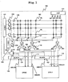
- FIG. 1 shows an example of the structure of the non-volatile semiconductor memory 100.
- the non-volatile semiconductor memory 100 is a NONOS type flash memory, which has a dual port.
- the dual port has sets of address and data buses; each exclusively for the corresponding one of the processors CPU0 and CPU1.
- the non-volatile semiconductor memory 100 has a set of ports PORTO and PORT1; the port PORT0 is connected to the processor CPU0 through the address bus ABUS0 and data bus DBUS0, and the port PORT1 is connected to the processor CPU1 through the address bus ABUS1 and data bus DBUS1.
- Such structure eliminates the need for an arbiter for performing arbitration at the time of occurrence of bus conflict, and the need for changing a circuit of a single-core CPU structure.
- address decode power supply to a selected word line WL; connection between a selected bit line and a sense amplifier; data sensing; and data output.
- a latch is placed in each of an address path and a data path.
- an address latch (ALACH) 101 operable to hold an address signal from the processor CPU0
- an address latch (ALACH) 102 operable to hold an address signal from the processor CPU1
- An address multiplexer 103 behind the address latches 101 and 102 selectively transfers output signals from the address latches 101 and 102 to a circuit in its subsequent stage.
- Word lines WL and bit lines BL are laid out so as to intersect one another; a memory cell MC is located at each intersection.
- the memory cell MC is a non-volatile memory cell as described later in detail.
- the memory cell MC is connected with the word line WL and bit line BL, and enables storage of a program and data.
- an X decoder (X-DEC) 121 for decoding a row address signal is provided.
- X-DEC X decoder
- a group of X decode latches 104 operable to hold a result of decode by the X decoder 121 are disposed.
- a word driver 106 is disposed corresponding to each X decode latch 104.
- the word driver 106 drives the word line WL to a select level.
- a Y decoder (Y-DEC) 122 for decoding a Y address signal is provided.
- a group of Y decode latches 105 operable to hold a result of decode by the Y decoder 122 are disposed.
- An output signal from each Y decode latch 105 is transferred to a column multiplexer (Y-MUX) 107 for selecting the bit lines BL.
- the selecting operation of the column multiplexer 107 is controlled. Further, in a stage subsequent to the column multiplexer 107, a sense amplifier 108 for sensing an output signal from the column multiplexer 107 is disposed. In a stage subsequent to the sense amplifier 108, a group of data latches 109 and 110 are disposed corresponding to the each sense amplifier 108. In the stage subsequent to each data latch 109, a bus driver (output buffer) 111 is disposed. An output signal form each data latch 109 is transferred to the processor CPU0 through the corresponding bus driver 111. Further, in the subsequent stage of each data latch 110, a bus driver 112 is disposed.
- a control circuit (CNT) 131 is provided in the non-volatile semiconductor memory.
- the control circuit 131 controls the operation of an important portion in the non-volatile semiconductor memory 100.
- the control circuit 131 produces various kinds of control signals including an address multiplexer control signal 201, a trigger 202 for X and Y decode latches, a trigger 203 for data latch of the output side of the processor CPU0, and a trigger 204 for data latch of the output side of the processor CPU1.
- the selecting operation of the address multiplexer 103 is controlled by the address multiplexer control signal 201.
- the trigger 202 for X and Y decode latches is used to control the operations of the X decode latch 104 and Y decode latch 105.
- the trigger 203 for data latch of the output side of the processor CPU0 is used to control the operation of the data latch 109.
- the trigger 204 for data latch of the output side of the processor CPU1 is used to control the operation of the data latch 110.
- X decode latches 104 are provided in the subsequent stage of the X decoder 121, and the Y decode latches 105 are disposed in the subsequent stage of the Y decoder 122, and the data latches 109 and 110 are disposed in the subsequent stage of each sense amplifier 108, which makes it possible to carry out a pipeline operation for data reading.
- the read latency can be kept below twice as high as in case of no conflict.
- FIG. 1 shows an example of the dual core structure having the processors CPU0 and CPU1
- the number of such processors are not limited particularly.
- the latency in case of occurrence of conflict among read accesses by n CPUs can be kept n times that in case of no conflict or below by application of a multi core structure with n CPUs, which results from expansion of a dual core structure.
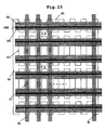
- FIG. 15 shows an example of the layout of the memory cells MC.
- the memory cells MC have a split gate type memory cell structure with a memory gate MG and a control gate CG, each can be regarded as a cell constituted by a combination of a MG-MOS and a CG-MOS connected in series; MG-MOS has a gate composed of the memory gate MG, and CG-MOS has a gate composed of the control gate CG. Each control gate CG corresponds to the word line.
- the CG-MOS is turned on by raising the voltage of the control gate CG, and a current depending on the threshold voltage Vth of MG-MOS is made to pass through the bit lines BL. While this is not shown in the drawing, data is read by a sense amplifier connected to each bit lines BL as follows.
- the logic value of data is made “1” in case that a current passing through the bit line BL is larger than a set threshold current, i.e. the threshold (Vth) of the memory cell MC is lower; the logic value of data is made "0" in case that the current passing through the bit line BL is smaller than the threshold current, i.e. the threshold (Vth) of the memory cell is higher.
- the drains of memory cells MC are paired in columns' direction i.e. a direction in parallel with the bit lines, and the drains of each pair share one contact CT and are connected through the contact CT to the corresponding bit line BL on a metal trace.
- the sources of the memory cells MC are connected through a diffusion layer DIF, which is connected through the contacts CT to source lines SL on the metal trace at intervals.
- formed is a parallel-connected NOR-type array that the memory cells MC arrayed in the columns' direction share the bit line BL, and all the memory cells share the source line SL.
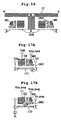
- FIG. 16 represents a cross sectional view of the memory cell MC (i.e. sectional view taken along the line A-A' of FIG. 15 ).
- a film stack consisting of silicon oxide, silicon nitride and silicon oxide (which is referred to as ONO film stack) is formed.
- a poly silicon memory gate MG is formed with ONO film stack left as a side wall.
- ONO film stack can be formed under the memory gate MG.
- the silicon nitride film is an insulator having a trapping ability.
- the threshold voltage (Vth) of MG-MOS is controlled by trapping charges, whereby data can be stored. After program and erase, charges are left trapped in the insulator film discretely. Therefore, an event that all of trapped charges are lost through defects in oxide film as in a floating gate type memory of low resistance is hard to occur, and such charge lost can be restricted only in the vicinities of defects. As a result, the oxide film can be thinned, and a relatively larger memory cell current in comparison to that in a floating gate type memory can be gained.
- the non-volatile semiconductor memory 100 can achieve a low-latency read because of its large memory cell current and read circuit using thin oxide devices.
- FIGs. 17A-17C show read, program and erase operations with respect to the memory cells MC.
- a high-potential-side source voltage Vdd is supplied to the drain D and control gate CG, and a predetermined voltage Vmg_read for read is supplied to the memory gate MG.
- the source is set to zero volt (ground level).
- the read operation is performed by making a judgment on whether or not the current 171 traveling between the source S and drain D is equal to or larger than the threshold current.
- the data programming to the memory cell MC is performed through a source side injection.
- the drain D is connected with a current source.
- the control gate CG, memory gate MG and source S are supplied with predetermined voltages Vcg_prog, Vmg_prog, and Vs_prog for programming, respectively.
- current 172 flows between the source S and drain D. Electrons of the current 172 are accelerated by a lateral electric field between the source and drain thereby to generate hot electrons having high energy.
- the hot electrons which have gained an energy over the height of energy barrier of the oxide go through the silicon oxide with the aid of the vertical electric field brought by high-voltage memory gate MG, and are trapped in the silicon nitride, whereby the threshold voltage Vth with respect to the memory gate MG is raised. In this way, the data programming is performed.
- Erasing data on the memory cell MC is performed through the band-to-band tunneling hot hole injection, as shown in FIG. 17C .
- band-to-band tunneling is caused by applying a positive voltage Vs_erase to the source S and biasing the memory gate MG with a negative voltage Vmg_erase, whereby the resultant hot holes are injected into the silicon nitride.
- Vs_erase positive voltage
- Vmg_erase negative voltage
- non-volatile semiconductor memory 100 Into the non-volatile semiconductor memory 100 are latched address signals on the address busses ABUS0 and ABUS1, which are output by the processors CPU0 and CPU1, at a rising edge of a bus clock BCLK.
- the following are performed: decoding the latched address signals, selecting the word line WL and bit line BL corresponding to the resultant addresses, supplying a voltage to the selected word line, and connecting the selected bit line BL with the corresponding sense amplifier 108.
- the sense amplifier 108 reads data from the selected memory cell MC.
- the data is output to the data bus DBUS0 or DBUS1.
- the data thus read is fetched by the processors CPU0 and CPU1 at a rising edge of the bus clock BCLK.
- the inside components of the processors CPU0 and CPU1 work in synchronization with the bus clock BCLK, and therefore the non-volatile semiconductor memory 100, and the processors CPU0 and CPU1 operate in synchronization with each other.
- the processors CPU0 and CPU1 each have an independent program counter and a register.
- the processors CPU0 and CPU1 can make requests for read to the non-volatile semiconductor memory 100 in the same bus clock cycle.
- the non-volatile semiconductor memory 100 latches address signals from the processors CPU0 and CPU1, which have been triggered by the same bus clock rising edge, into the address latches 101 and 102.
- an address requested by the processor CPU0 is denoted by A0
- an address requested by the processor CPU1 is denoted by A1.
- the address multiplexer 103 placed in the subsequent stage of the address latches 101 and 102 first selects an output from the address latch 101, i.e. the address A0 from the processor CPU0, and sends the X and Y decoders 121 and 122 the address A0, or only bits of the address A0 respectively required for the X and Y decoders 121 and 122.
- the X and Y decoders 121 and 122 decode the address A0 to decide the selected word line WL and selected bit line BL.
- the longer time is referred to as "decode time”.
- the decode time varies depending on the variations of power supply voltage, operation temperature and process. Therefore, a length of time resulting from addition of a margin to the decode time under the worst condition shall be herein denoted by T1 as shown in FIG. 2 .
- the time T1 represents the worst delay time from the address latches 101 and 102 to the X decode latch 104 or Y decode latch 122 plus a margin.
- the address latch 102 is selected according to the address multiplexer control signal 201. Further, at the same timing, a trigger 202 for the X and Y decode latches 104 and 105 is asserted. Although no special restriction is intended, using the X and Y decode latches 104 and 105 each composed of an edge trigger type D-flip flop can ease the restriction in design of timing rather than using transparent latches. One of functions of these latches is to latch input data using a rising edge of the trigger signal to update their contents and outputs.
- the word driver 106 supplies a voltage to the selected word line WL in accordance with the content of the X decode latch 104, and the column multiplexer 107 connect s between the selected bit line BL and sense amplifier 108 in accordance with the content of the Y decode latch 105.
- the sense amplifier 108 makes a judgment on whether data is 0 or 1 from the voltage of the selected bit line BL.
- decode of the requested address A1 is triggered by switching of the control signal 201 of the address multiplexer 103.
- T2 a length of time resulting from addition of a margin to the worst time required to set up the selected word line WL, connect between the selected bit line BL and sense amplifier 108 in charge, and determine the data read by the sense amplifier 108 shall be herein denoted by T2 as shown in FIG. 2 .
- a trigger 203 for a data latch 109 of the output side of the processor CPU0 is started, and data D0 stored at the address A0 is latched in the data latch 109.
- the data latch 109 may be composed of a positive edge trigger type D-flip flop.
- the trigger 202 for the X and Y decode latches 104 and 105 is started, and the result of decode of the address A1 is output to the relevant word driver 106 and column multiplexer 107.
- the bus driver 111 begins driving a data bus, and the data D0 is output to the processor CPU0.
- setup of the selected word line by the word driver 106 and connection between the selected bit line and relevant sense amplifier (108) are begun based on the result of decode of the address A1, whereby the sense amplifier reads data D1.
- T3 the worst delay time from the time when the data D0 left the data latch 109 to the time when the data D0 reaches the processor CPU0 through the bus driver 111 is herein denoted by T3.
- the trigger 204 for the data latch 110 in charge of the processor CPU1 is started to latch the data D1.
- the data latch 110 may be composed of a positive edge trigger type D-flip flop like the data latch 109.
- the data D1 is output to the processor CPU1 through the bus driver 112. Specifically, at the time when the time "T1+T2+T2+T3" elapses after the rising edge of the bus clock, sending of the data D1 to the processor CPU1 is completed.
- timings of T1, T2, T3 can be created by a delay circuit on the basis of the bus clock BCLK.
- two or more delay circuits are prepared, by which the bus clock is delayed.
- pulses with any waveform can be materialized.
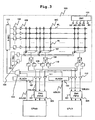
- FIG. 3 shows an example of another structure of the multi processor system 10.
- the non-volatile semiconductor memory 100 shown in FIG. 3 differs from that shown in FIG. 1 significantly in that first-in first-out buffers (2-bit FIFO) 303 and 304 which take a 2-bit structure of address bus ABUS and data bus DBUS are provided.
- the operations of the 2-bit FIFOs 303 and 304 are controlled in accordance with a 2-bit FIFO trigger signal 401 produced by the control circuit 131.
- the first embodiment requires that the read from the non-volatile semiconductor memory should meet the following condition expressed using the clock cycle TCLK defined as shown in FIG. 2 and the time lengths T1 to T3: T1+2T2+T3 ⁇ TCLK".
- the difference in speed between CPUs and memories tends to expand year by year in general. Therefore, it is difficult to meet the condition as described above except when a very high performance is not required and the CPUs' clocks are at most tens of megahertz.
- FIG. 4 presents an operation timing chart in connection with the structure as shown in FIG. 3 .
- the following condition holds: 1TCLK ⁇ T1+T2+T3 ⁇ 2TCLK.
- the read latency is 2TCLK. Therefore, if no pipeline structure is constructed for a read operation in the non-volatile semiconductor memory 100, the read latency at the time of occurrence of conflict between read accesses from the processors CPU0 and CPU1 would be 4TCLK. Therefore, three stages pipelines for decode, select of the word line WL and read through it, and data output are herein built as shown in FIG. 4 to meet the condition "T1+2T2+T3 ⁇ 2TCLK". As a result, it becomes possible for both the processors CPU0 and CPU1 to read with a latency of 2TCLK.
- a read operation is performed based on the output of the data D0 and result of decode of the address A1.
- the decoders have already finished decode of the addresses A0 and A1, and therefore they can accept and begin decoding a subsequent address.
- the address A2 from the processor CPU0 and the address A3 from the processor CPU1 are latched in the address latch 301 and the address latch 302. After that, the pipeline operations are performed in the same way as in the case of the addresses A0 and A1.
- the data D2 has been already driven onto the data bus of the processor CPU0 at the time when the processor CPU0 attempts to fetch the data D0 at the third bus clock rising edge, as shown in FIG. 4 .
- the processors CPU0 and CPU1 each have some buffer memory.
- FIFOs 303 and 304 configured of two bits or larger as shown in FIG. 3 may suffice.
- the 2-bit FIFOs 303 and 304 are provided with two rows of latches. Data from the non-volatile semiconductor memory 100 are written into the two rows of latches alternately. The data thus written are alternately output to the processors CPU0 and CPU1 in the order in which the data are written.
- the timing of write into the 2-bit FIFOs 303 and 304 may be after data output onto the data bus have reached an input portion of each FIFO and before subsequent data start activating the data buses.
- the 2-bit FIFO trigger signal 401 used for that is produced in the control circuit 131 so that the signal is asserted into its high level at the times as shown in FIG. 4 .
- the control circuit 131 uses an appropriate delay circuit to delay a signal with respect to an edge of the bus clock BCLK, thereby to produce the trigger signal.
- the read latency is 2TCLK because of the system layout that the 2-bit FIFOs 303 and 304 are placed in positions near the CPUs on the data buses as shown in FIG. 3 , and the condition of "T1+T3 ⁇ TCLK" and "2T2 ⁇ TCLK” as shown in FIG. 4 .
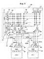
- FIG. 5 shows an example of another structure of the multi processor system 10.
- the multi processor system shown in FIG. 5 differs from that shown in FIG. 3 in that the read latency is improved by cache memories (CMEM) 501 and 502 disposed between the processors CPU0 and CPU1 and the non-volatile semiconductor memory 100.
- CMEM cache memories
- the multi processor system in accordance with the second embodiment offers a sufficient throughput because an address can be accepted to output data every clock cycle.
- the read latency is 2TCLK, which has the effect of reducing the latency at the time of occurrence of read conflict between two CPUs by half, however cannot shorten the read latency per read to 1TCLK.
- low-latency cache memories 501 and 502 are placed between the processors CPU0 and CPU1 and the non-volatile semiconductor memory 100 as shown in FIG. 5 .
- the cache memories 501 and 502 each offer a latency of 1TCLK and have a performance that execution of hit decision and read are enabled.
- Such cache memories 501 and 502 may be composed of static RAMs (Random Access Memory), or low-latency memories such as flip flops. However, no special restriction is intended in this respect.
- the processors CPU0 and CPU1 output address signals to the cache memories 501 and 502, respectively.
- detection is made based on tag data about whether or not data corresponding to the address signals sent from the processors CPU0 and CPU1 have been stored in their memories. If the cache memories 501 and 502 have the data corresponding the address signals therein, the result of the detection is a cache hit. Then, the cache memories 501 and 502 output the data corresponding to the address to the processors CPU0 and CPU1 respectively. If the cache memories 501 and 502 have no such data therein, the result of the detection is a cache miss. Then, the cache memories 501 and 502 pass the address signals to the non-volatile semiconductor memory 100 to read data, and perform output of the data to the processors CPU0 and CPU1, and write of the data into the cache memories 501 and 502.
- the latency is 1TCLK at the time of cache hit, and 2TCLK at the time of cache miss, which corresponds to the read latency.
- the cache memories increase the footprint and cost of the chip.
- the cache memories have an advantage that the peak performance can be enhanced.
- the construction of a pipeline structure of read operations of the non-volatile semiconductor memory 100 exerts an effect in case that cache miss occurs, in regard to both the processors CPU0 and CPU1.
- the cache hit ratio depends on the configuration and capacities of cache memories, and a user program.
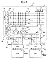
- FIG. 6 shows an example of another structure of the multi processor system 10.
- the multi processor system 10 shown in FIG. 6 has cache memories 501 and 502 between the processors CPU0 and CPU1, and non-volatile semiconductor memory 100 respectively, as in the case of the third embodiment.
- the multi processor system 10 shown in FIG. 6 differs from that in accordance with the third embodiment shown in FIG. 5 in the following point. That is, sufficiently large widths of the data buses DBUS0 and DBUS1 between the non-volatile semiconductor memory 100 and the cache memories 501 and 502 are ensured to lower the probability of occurrence of successive cache misses, whereby the restriction on the speed of the non-volatile semiconductor memory 100 is eased without causing a large deterioration in performance in comparison to the system in accordance with the third embodiment.
- the width of the data buses DBUS0 and DBUS1 between the non-volatile semiconductor memory 100 and the cache memories 501 and 502 shall be N bits; the width of the data buses DBUS01 and DBUS11 between the cache memories 501 and 502 and the processors CPU0 and CPU1 shall be M bits.
- N is sufficiently larger than M, a larger amount of data can be read from the non-volatile semiconductor memory 100, and written into the cache memories 501 and 502 by one read operation at the time of occurrence of cache miss. Therefore, it is expected that making N sufficiently larger than M can lower the probability of occurrence of successive cache misses as long as sufficiently large capacities of the cache memories 501 and 502 are ensured.
- N is sufficiently larger, it is expected that the effect of performing acceptance of an address and data output every clock cycle at the second read and later as in the second embodiment of FIG. 4 is weakened. Therefore, the restriction on the speed of a read operation from the non-volatile semiconductor memory 100 can be eased by making N larger.
- N can be made larger by increasing the number of the sense amplifiers 108, decreasing inputs to the column multiplexer 107, and decreasing the number of bit lines per sense amplifier 108.
- FIG. 7 shows the operation timing in connection with the multi processor system shown in FIG. 6 .
- the situations in the first to third bus clocks are as follows. In the first bus clock, both the processors CPU0 and CPU1 go into cache miss. Then, these reads are performed on the non-volatile semiconductor memory over 2TCLK. In the third bus clock, cache hits take place.
- N is set to be sufficiently large, the probability of occurrence of such successive cache misses is small. Therefore, it is expected that making N sufficiently larger than M can ease the restriction on the speed of reading the non-volatile semiconductor memory 100, and the performance is not deteriorated to a larger extent in comparison to that achieved in accordance with the third embodiment.
- the third embodiment differs from the second embodiment just in that cache memories 501 and 502 are added therein. Therefore, the condition making a restriction on the speed of reading the non-volatile semiconductor memory 100 in accordance with the third embodiment is "T1+2T2+T3 ⁇ 2TCLK" and "2T2 ⁇ TCLK", which is the same as that in the second embodiment. However, in the fourth embodiment, such restriction can be eased to just "T1+2T2+T3 ⁇ 2TCLK". In addition, the overwrite of data on the data bus as cited in the description concerning the second embodiment does not occur. Therefore, the need for 2-bit FIFOs 303 and 304 as shown in FIGs. 3 and 5 is eliminated.
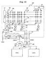
- FIG. 8 shows an example of another structure of the multi processor system 10.
- the address and data busses are decreased in number of lines, and the chip area is reduced.
- the processors CPU0 and CPU1 each have independent address and data buses.
- the address and data buses are shared by the processors CPU0 and CPU1, which makes it possible to reduce the number of these long bus lines and chip area.
- a shared address bus CABUS, and a shared data bus CDBUS are provided instead, which are shared by the processors CPU0 and CPU1.
- a right of the processor CPU0 to use a bus and a right of the processor CPU1 to use a bus, and an arbiter (ARB) 801 for arbitration of conflict are provided.
- the arbiter 801 provides the right to possess the shared address bus CABUS to one of the processors, and notifies the other processor that the shared address bus CABUS is busy.
- FIG. 9 shows the operation timing in connection with the multi processor system shown in FIG. 8 .
- the arbiter 801 provides the processor CPU0 with the right to use the address bus, and allows the processor CPU0 to send an address A0 to the non-volatile semiconductor memory.
- the arbiter 801 notifies the processor CPU1 that the shared address bus CABUS is busy, and it is required to wait for 1TCLK to elapse.
- the non-volatile semiconductor memory 100 undergoes read in connection with the address A0. Then, the non-volatile semiconductor memory 100 outputs data D0 to the processor CPU0 through the shared data bus CBUS and arbiter 801.
- the processor CPU0 acquires data D0 2TCLK behind the data read request in connection with the address A0 at the rising edge of the bus clock BCLK.
- the arbiter 801 sends an address A1 to the non-volatile semiconductor memory 100 1TCLK behind the data request in connection with the address A0 from the processor CPU0. Then, the non-volatile semiconductor memory 100 begins decoding the address A1 in parallel with reading data D0. 2TCLK behind the sending of the address A1 to the non-volatile semiconductor memory 100, i.e. 3TCLK behind the data read request in connection with the address A1, output of data D1 is completed.
- the data D1 be output after elapse of 3TCLK i.e. this 2TCLK plus 1TCLK for waiting for using the address bus, and the processor CPU1 can acquire this.
- the read latency at the time of cache hit is 1TCLK.
- the latency at the time of cache miss is 2TCLK without the conflict of the shared address bus.
- the latency is 3TCLK for CPU which is made to wait for using the address bus.
- FIG. 10 shows an example of another structure of the multi processor system 10.
- shared address buses CABUS and CDBUS are shared by the processors CPU0 and CPU1.
- both rising and falling edges of the bus clock BCLK are used to send an address at double the transfer rate despite of reducing the area of wiring lines, whereby the read latency is shortened.
- Address signals from the processors CPU0 and CPU1 are selectively transferred to the non-volatile semiconductor memory 100 by the address multiplexer (MUX) 1001.
- MUX address multiplexer
- Output data of the bus driver 112 are transferred to the processors CPU0 and CPU1 through the shared data bus CDBUS and 2-bit FIFO 1007.
- the non-volatile semiconductor memory 100 is provided with address latches (ALACH) 1003 and 1004, which are operated in synchronization with the bus clock BCLK, and an address multiplexer 1005.
- Address signals from the processors CPU0 and CPU1 are sent to the address multiplexer 1001, allocated to the address latches 1003 and 1004 by the address multiplexer, and then held by the address latches.
- the address signals stored in the address latches 1003 and 1004 are selectively transferred to the X decoder 121 and Y decoder 122 by the address multiplexer 1005.
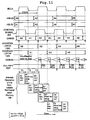
- FIG. 11 shows the operation timing in connection with the multi processor system shown in FIG. 10 .
- Addresses output from the processors CPU0 and CPU1 are multiplexed by the address multiplexer 1001, and sent to the non-volatile semiconductor memory 100 through the shared address bus CABUS at double the transfer rate.
- the address multiplexer control signal 205 has the same frequency as that of the bus clock BCLK, which the control circuit 131 produces by delaying the bus clock.
- the address multiplexer 1001 selects an address in association with the processor CPU0 when the address multiplexer control signal 205 has a logical value "1". When the address multiplexer control signal 205 has a logical value "0", the address multiplexer selects an address in association with the processor CPU1.
- an address coming from the processor CPU0 has reached the non-volatile semiconductor memory 100 at a rising edge of the bus clock BCLK when viewed from the non-volatile semiconductor memory 100, and an address coming from the processor CPU1 has reached the non-volatile semiconductor memory 100 at a falling edge.
- an address latch 1003 operable to latch an address at a rising edge of the bus clock BCLK, and an address latch 1004 operable to latch an address at a falling edge thereof are provided.
- the address multiplexer 1005 which is disposed in a stage subsequent to the address latches 1003 and 1004, is controlled using the bus clock BCLK.
- an address coming from the processor CPU0 and an address coming from the processor CPU1 are sent to the X and Y decoders 121 122 every half TCLK, and therefore it becomes possible to decode two addresses within 1TCLK.
- pipeline operations of lengths of T1, T2 and T3 are performed.
- An operation of the same frequency as that of CPU such as successively accepting two addresses from the processors CPU0 and CPU1 with the cycle of TCLK and then outputting two pieces of data, can be performed as long as the condition "T1+T3 ⁇ TCLK" and "2T2 ⁇ TCLK" is satisfied.
- the latency of each read is 2TCLK.
- an FIFO 1007 of two bits or larger is required as in the second and third embodiments.
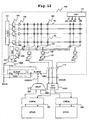
- FIG. 12 shows an example of another structure of the multi processor system 10.
- the structure of the multi processor system shown in FIG. 12 differs from that of FIG. 10 in that cache memories (CMEM) 501 and 502 are provided between the processors CPU0 and CPU1 and the non-volatile semiconductor memory 100 respectively, whereby the read latency is improved.
- CMEM cache memories
- the sixth embodiment is sufficient in throughput because acceptance of an address and data output every clock cycle can be achieved.
- 2TCLK the read latency of 2TCLK
- the effect of reducing by half the latency at the time of occurrence of the conflict of reads by two CPUs it is impossible to shorten the latency to 1TCLK at one read.
- low-latency cache memories 501 and 502 are provided between the processors CPU0 and CPU1 and the non-volatile semiconductor memory 100.
- the cache memories 501 and 502 are composed of low-latency memories, such as SRAMs and flip flops.
- the read latency is 1TCLK at the time of cache hit, and 2TCLK at the time of cache miss. Therefore, this multi processor system is advantageous in that the peak performance is improved despite of the increase in chip area and the rise in cost owing to the addition of the cache memories.
- the application of the pipeline control to an operation to read the non-volatile semiconductor memory 100 exerts an effect when both the processors CPU0 and CPU1 go into cache miss.
- the cache hit ratio depends on the configuration and capacities of cache memories, and a user program.
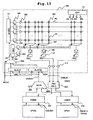
- FIG. 13 shows an example of another structure of the multi processor system 10.
- cache memories 501 and 502 are provided between the processors CPU0 and CPU1 and the non-volatile semiconductor memory 100 respectively, as in the case of the seventh embodiment.
- the multi processor system 10 shown in FIG. 13 largely differs from that in accordance with the seventh embodiment in the following point. That is, the sufficiently large width of the shared data bus CDBUS between the non-volatile semiconductor memory 100 and the cache memories 501 and 502 is ensured to lower the probability of occurrence of successive cache misses, whereby the restriction on the speed of the non-volatile semiconductor memory 100 is eased without causing a large deterioration in performance in comparison to the system in accordance with the seventh embodiment.
- the width of the shared data buses CDBUS between the non-volatile semiconductor memory 100 and the cache memories 501 and 502 shall be N bits; the width of the data buses DBUS01 and DBUS11 between the cache memories 501 and 502, and the processors CPU0 and CPU1 shall be M bits.
- N is sufficiently larger than M, a larger amount of data can be read from the non-volatile semiconductor memory 100, and written into the cache memories 501 and 502 by one read operation at the time of occurrence of cache miss. Therefore, it is expected that making N sufficiently larger than M can lower the probability of occurrence of successive cache misses as long as sufficiently large capacities of the cache memories 501 and 502 are ensured.
- N is sufficiently larger, it is expected that the effect of performing acceptance of an address and data output every clock cycle at the second read and later as in the sixth embodiment of FIG. 11 is weakened. Therefore, the restriction on the speed of a read operation from the non-volatile semiconductor memory can be eased by making N larger.
- N can be made larger by increasing the number of the sense amplifiers, decreasing inputs to the column multiplexer, and decreasing the number of bit lines per sense amplifier.
- FIG. 14 shows the operation timing in connection with the multi processor system shown in FIG. 13 .
- the situations in the first to third bus.clocks are as follows.
- both the processors CPU0 and CPU1 go into cache miss.
- these reads are performed on the non-volatile semiconductor memory 100 over 2TCLK.
- cache hits take place for both the addresses A2 and A3. Therefore, as to addresses after the addresses A2 and A3, the address signals are not sent to the non-volatile semiconductor memory 100. If cache miss occurs with the addresses A2 and A3 trailing the addresses A0 and A1, the outputs of the data D2 and D3 will be delayed by 1TCLK in comparison to the example of FIG. 11 .
- N is set to be sufficiently large, the probability of occurrence of such successive cache misses is small. Therefore, it is expected that making N sufficiently larger than M can ease the restriction on the speed of reading the non-volatile semiconductor memory 100, and the performance is not deteriorated to a larger extent in comparison to that achieved in accordance with the seventh embodiment.
- the seventh embodiment differs from the sixth embodiment just in that cache memories 501 and 502 are added therein. Therefore, the condition making a restriction on the speed of reading the non-volatile semiconductor memory 100 in accordance with the seventh embodiment is "T1+2T2+T3 ⁇ 2TCLK" and "2T2 ⁇ TCLK", which is the same as that in the sixth embodiment. However, in the eighth embodiment, such restriction can be eased to just "T1+2T2+T3 ⁇ 2TCLK".
- the invention is applicable on condition that such semiconductor integrated circuit devices include at least a non-volatile semiconductor memory.
Landscapes
- Engineering & Computer Science (AREA)
- Multimedia (AREA)
- Read Only Memory (AREA)
- Memory System (AREA)
Applications Claiming Priority (1)
| Application Number | Priority Date | Filing Date | Title |
|---|---|---|---|
| JP2007297479A JP2009123298A (ja) | 2007-11-16 | 2007-11-16 | 半導体集積回路装置 |
Publications (2)
| Publication Number | Publication Date |
|---|---|
| EP2065893A1 EP2065893A1 (en) | 2009-06-03 |
| EP2065893B1 true EP2065893B1 (en) | 2012-06-06 |
Family
ID=40303728
Family Applications (1)
| Application Number | Title | Priority Date | Filing Date |
|---|---|---|---|
| EP08253714A Expired - Fee Related EP2065893B1 (en) | 2007-11-16 | 2008-11-13 | Semiconductor integrated circuit device |
Country Status (4)
| Country | Link |
|---|---|
| US (1) | US7848177B2 (enExample) |
| EP (1) | EP2065893B1 (enExample) |
| JP (1) | JP2009123298A (enExample) |
| CN (1) | CN101436430B (enExample) |
Families Citing this family (19)
| Publication number | Priority date | Publication date | Assignee | Title |
|---|---|---|---|---|
| KR101644169B1 (ko) | 2010-04-29 | 2016-08-01 | 삼성전자주식회사 | 비휘발성 메모리 장치 및 이를 포함하는 비휘발성 메모리 시스템 |
| TW201225529A (en) * | 2010-12-03 | 2012-06-16 | Fortune Semiconductor Corp | Test mode controller and electronic apparatus with self-testing thereof |
| US8593878B2 (en) | 2011-11-17 | 2013-11-26 | Macronix International Co., Ltd. | Program method and flash memory using the same |
| CN103514956B (zh) * | 2012-06-15 | 2016-04-13 | 晶豪科技股份有限公司 | 半导体存储器元件及其测试方法 |
| US9190172B2 (en) * | 2013-01-24 | 2015-11-17 | Semiconductor Energy Laboratory Co., Ltd. | Semiconductor device |
| JP6359491B2 (ja) * | 2015-06-12 | 2018-07-18 | 東芝メモリ株式会社 | 半導体記憶装置 |
| US11048583B1 (en) * | 2015-09-11 | 2021-06-29 | Green Mountain Semiconductor Inc. | Flexible, low-latency error correction architecture for semiconductor memory products |
| DE102015221064A1 (de) * | 2015-10-28 | 2017-05-04 | Robert Bosch Gmbh | Anordnung aus wenigstens zwei Mikrocontrollern und Verfahren zur Herstellung einer solchen Anordnung |
| KR102557324B1 (ko) * | 2016-02-15 | 2023-07-20 | 에스케이하이닉스 주식회사 | 메모리 장치 |
| KR102682253B1 (ko) * | 2016-11-29 | 2024-07-08 | 에스케이하이닉스 주식회사 | 메모리 시스템 및 메모리 시스템의 동작방법 |
| US9997212B1 (en) * | 2017-04-24 | 2018-06-12 | Micron Technology, Inc. | Accessing data in memory |
| US10347307B2 (en) * | 2017-06-29 | 2019-07-09 | SK Hynix Inc. | Skew control circuit and interface circuit including the same |
| JP2019040646A (ja) * | 2017-08-22 | 2019-03-14 | 東芝メモリ株式会社 | 半導体記憶装置 |
| US11360704B2 (en) | 2018-12-21 | 2022-06-14 | Micron Technology, Inc. | Multiplexed signal development in a memory device |
| CN111489773B (zh) * | 2019-01-29 | 2023-04-07 | 合肥格易集成电路有限公司 | 一种读取数据的电路、非易失存储器以及读取数据的方法 |
| US11676657B2 (en) * | 2020-04-16 | 2023-06-13 | Mediatek Inc. | Time-interleaving sensing scheme for pseudo dual-port memory |
| US11443823B2 (en) * | 2020-10-29 | 2022-09-13 | SambaNova Systems, Inc. | Method and circuit for scan dump of latch array |
| US12321262B2 (en) * | 2020-12-28 | 2025-06-03 | Kioxia Corporation | Memory system which orders data fetching from a latch circuit during execution of a read operation |
| JP7614966B2 (ja) * | 2021-07-14 | 2025-01-16 | キオクシア株式会社 | 半導体記憶装置 |
Family Cites Families (9)
| Publication number | Priority date | Publication date | Assignee | Title |
|---|---|---|---|---|
| JP2855633B2 (ja) | 1989-02-03 | 1999-02-10 | ミノルタ株式会社 | マルチプロセッサシステムにおけるデュアルポートメモリの故障診断装置 |
| JP2830594B2 (ja) | 1992-03-26 | 1998-12-02 | 日本電気株式会社 | 半導体メモリ装置 |
| US5375089A (en) | 1993-10-05 | 1994-12-20 | Advanced Micro Devices, Inc. | Plural port memory system utilizing a memory having a read port and a write port |
| JP2001306307A (ja) | 2000-04-25 | 2001-11-02 | Hitachi Ltd | ファームウェアの処理方法。 |
| JP4704541B2 (ja) * | 2000-04-27 | 2011-06-15 | エルピーダメモリ株式会社 | 半導体集積回路装置 |
| US6246634B1 (en) | 2000-05-01 | 2001-06-12 | Silicon Storage Technology, Inc. | Integrated memory circuit having a flash memory array and at least one SRAM memory array with internal address and data bus for transfer of signals therebetween |
| JP4331966B2 (ja) | 2003-04-14 | 2009-09-16 | 株式会社ルネサステクノロジ | 半導体集積回路 |
| US7349285B2 (en) | 2005-02-02 | 2008-03-25 | Texas Instruments Incorporated | Dual port memory unit using a single port memory core |
| JP2007297479A (ja) | 2006-04-28 | 2007-11-15 | Hitachi Chem Co Ltd | 樹脂組成物及び電気機器絶縁物の製造方法 |
-
2007
- 2007-11-16 JP JP2007297479A patent/JP2009123298A/ja active Pending
-
2008
- 2008-11-12 US US12/269,098 patent/US7848177B2/en not_active Expired - Fee Related
- 2008-11-13 EP EP08253714A patent/EP2065893B1/en not_active Expired - Fee Related
- 2008-11-13 CN CN2008101814389A patent/CN101436430B/zh not_active Expired - Fee Related
Also Published As
| Publication number | Publication date |
|---|---|
| CN101436430B (zh) | 2012-02-29 |
| EP2065893A1 (en) | 2009-06-03 |
| US7848177B2 (en) | 2010-12-07 |
| JP2009123298A (ja) | 2009-06-04 |
| CN101436430A (zh) | 2009-05-20 |
| US20090129173A1 (en) | 2009-05-21 |
Similar Documents
| Publication | Publication Date | Title |
|---|---|---|
| EP2065893B1 (en) | Semiconductor integrated circuit device | |
| US7586794B2 (en) | Methods of reading data including comparing current and previous section addresses and related devices | |
| EP2652741B1 (en) | Memory controller and method for interleaving dram and mram accesses | |
| US8111562B2 (en) | Semiconductor storage device and method of reading data therefrom | |
| US8189424B2 (en) | Semiconductor memory device having plurality of types of memories integrated on one chip | |
| US7369447B2 (en) | Random cache read | |
| US20140254267A1 (en) | Memory devices with different sized blocks of memory cells and methods | |
| US11269779B2 (en) | Memory system with a predictable read latency from media with a long write latency | |
| US9355051B2 (en) | Apparatus, method, and manufacture for using a read preamble to optimize data capture | |
| US6657913B2 (en) | Array organization for high-performance memory devices | |
| US8140778B1 (en) | Apparatus and method for data capture using a read preamble | |
| US11423958B2 (en) | Semiconductor memory device having a first plane and a second plane including respective latch circuits, and first and second FIFO circuits for fetching read data from the latch circuits | |
| TWI683310B (zh) | 波管線 | |
| US7542355B2 (en) | Semiconductor storage device | |
| US7483334B2 (en) | Interleaved input signal path for multiplexed input | |
| US7701781B2 (en) | Semiconductor memory device with memory cell including a charge storage layer and a control gate and method of controlling the same | |
| US6292401B1 (en) | Method and apparatus for global bitline multiplexing for a high-speed memory | |
| US6747898B2 (en) | Column decode circuit for high density/high performance memories | |
| JP2001229674A (ja) | 半導体装置 | |
| US9349461B1 (en) | Applying substantially the same voltage differences across memory cells at different locations along an access line while programming | |
| US9223726B2 (en) | Apparatus and method for programmable read preamble with training pattern | |
| JP4650900B2 (ja) | 半導体装置 | |
| US8990605B2 (en) | Apparatus and method for read preamble disable | |
| US8037231B2 (en) | Memory architecture for separation of code and data in a memory device | |
| US20120155191A1 (en) | Semiconductor memory device |
Legal Events
| Date | Code | Title | Description |
|---|---|---|---|
| PUAI | Public reference made under article 153(3) epc to a published international application that has entered the european phase |
Free format text: ORIGINAL CODE: 0009012 |
|
| 17P | Request for examination filed |
Effective date: 20081201 |
|
| AK | Designated contracting states |
Kind code of ref document: A1 Designated state(s): AT BE BG CH CY CZ DE DK EE ES FI FR GB GR HR HU IE IS IT LI LT LU LV MC MT NL NO PL PT RO SE SI SK TR |
|
| AX | Request for extension of the european patent |
Extension state: AL BA MK RS |
|
| 17Q | First examination report despatched |
Effective date: 20091125 |
|
| AKX | Designation fees paid |
Designated state(s): DE FR GB IT |
|
| RAP1 | Party data changed (applicant data changed or rights of an application transferred) |
Owner name: RENESAS ELECTRONICS CORPORATION |
|
| REG | Reference to a national code |
Ref country code: DE Ref legal event code: R079 Ref document number: 602008016158 Country of ref document: DE Free format text: PREVIOUS MAIN CLASS: G11C0007100000 Ipc: G11C0016260000 |
|
| GRAP | Despatch of communication of intention to grant a patent |
Free format text: ORIGINAL CODE: EPIDOSNIGR1 |
|
| RIC1 | Information provided on ipc code assigned before grant |
Ipc: G11C 7/10 20060101ALI20111123BHEP Ipc: G11C 16/26 20060101AFI20111123BHEP |
|
| GRAS | Grant fee paid |
Free format text: ORIGINAL CODE: EPIDOSNIGR3 |
|
| RBV | Designated contracting states (corrected) |
Designated state(s): DE |
|
| GRAA | (expected) grant |
Free format text: ORIGINAL CODE: 0009210 |
|
| AK | Designated contracting states |
Kind code of ref document: B1 Designated state(s): DE |
|
| REG | Reference to a national code |
Ref country code: DE Ref legal event code: R096 Ref document number: 602008016158 Country of ref document: DE Effective date: 20120802 |
|
| PGFP | Annual fee paid to national office [announced via postgrant information from national office to epo] |
Ref country code: DE Payment date: 20121126 Year of fee payment: 5 |
|
| PLBE | No opposition filed within time limit |
Free format text: ORIGINAL CODE: 0009261 |
|
| STAA | Information on the status of an ep patent application or granted ep patent |
Free format text: STATUS: NO OPPOSITION FILED WITHIN TIME LIMIT |
|
| 26N | No opposition filed |
Effective date: 20130307 |
|
| REG | Reference to a national code |
Ref country code: DE Ref legal event code: R097 Ref document number: 602008016158 Country of ref document: DE Effective date: 20130307 |
|
| REG | Reference to a national code |
Ref country code: DE Ref legal event code: R119 Ref document number: 602008016158 Country of ref document: DE |
|
| PG25 | Lapsed in a contracting state [announced via postgrant information from national office to epo] |
Ref country code: DE Free format text: LAPSE BECAUSE OF NON-PAYMENT OF DUE FEES Effective date: 20140603 |
|
| REG | Reference to a national code |
Ref country code: DE Ref legal event code: R119 Ref document number: 602008016158 Country of ref document: DE Effective date: 20140603 |