EP2065877B1 - Bildprojektionssystem mittels einer hochspannungsentladungslampe des gleichstromtyps - Google Patents
Bildprojektionssystem mittels einer hochspannungsentladungslampe des gleichstromtyps Download PDFInfo
- Publication number
- EP2065877B1 EP2065877B1 EP06798402A EP06798402A EP2065877B1 EP 2065877 B1 EP2065877 B1 EP 2065877B1 EP 06798402 A EP06798402 A EP 06798402A EP 06798402 A EP06798402 A EP 06798402A EP 2065877 B1 EP2065877 B1 EP 2065877B1
- Authority
- EP
- European Patent Office
- Prior art keywords
- discharge lamp
- color filter
- pressure discharge
- synchronization signal
- image projection
- Prior art date
- Legal status (The legal status is an assumption and is not a legal conclusion. Google has not performed a legal analysis and makes no representation as to the accuracy of the status listed.)
- Expired - Fee Related
Links
- 230000003287 optical effect Effects 0.000 claims description 23
- 230000004907 flux Effects 0.000 claims description 17
- 239000003086 colorant Substances 0.000 claims description 9
- 239000002699 waste material Substances 0.000 description 5
- 230000000694 effects Effects 0.000 description 4
- 238000010891 electric arc Methods 0.000 description 4
- 238000000034 method Methods 0.000 description 4
- 230000001360 synchronised effect Effects 0.000 description 3
- 230000001174 ascending effect Effects 0.000 description 2
- 230000008901 benefit Effects 0.000 description 2
- 230000008859 change Effects 0.000 description 2
- 230000002542 deteriorative effect Effects 0.000 description 2
- 238000010586 diagram Methods 0.000 description 2
- 238000001704 evaporation Methods 0.000 description 2
- 230000008020 evaporation Effects 0.000 description 2
- 230000001747 exhibiting effect Effects 0.000 description 2
- 230000000630 rising effect Effects 0.000 description 2
- 230000000903 blocking effect Effects 0.000 description 1
- 230000003247 decreasing effect Effects 0.000 description 1
- 230000005684 electric field Effects 0.000 description 1
- 238000002474 experimental method Methods 0.000 description 1
- 238000010438 heat treatment Methods 0.000 description 1
- 229910001507 metal halide Inorganic materials 0.000 description 1
- 150000005309 metal halides Chemical class 0.000 description 1
- 230000000737 periodic effect Effects 0.000 description 1
- 230000008569 process Effects 0.000 description 1
- 239000004065 semiconductor Substances 0.000 description 1
- 238000000926 separation method Methods 0.000 description 1
- 230000001629 suppression Effects 0.000 description 1
- 230000001052 transient effect Effects 0.000 description 1
- WFKWXMTUELFFGS-UHFFFAOYSA-N tungsten Chemical compound [W] WFKWXMTUELFFGS-UHFFFAOYSA-N 0.000 description 1
- 229910052721 tungsten Inorganic materials 0.000 description 1
- 239000010937 tungsten Substances 0.000 description 1
Images


Classifications
-
- G—PHYSICS
- G09—EDUCATION; CRYPTOGRAPHY; DISPLAY; ADVERTISING; SEALS
- G09G—ARRANGEMENTS OR CIRCUITS FOR CONTROL OF INDICATING DEVICES USING STATIC MEANS TO PRESENT VARIABLE INFORMATION
- G09G3/00—Control arrangements or circuits, of interest only in connection with visual indicators other than cathode-ray tubes
- G09G3/001—Control arrangements or circuits, of interest only in connection with visual indicators other than cathode-ray tubes using specific devices not provided for in groups G09G3/02 - G09G3/36, e.g. using an intermediate record carrier such as a film slide; Projection systems; Display of non-alphanumerical information, solely or in combination with alphanumerical information, e.g. digital display on projected diapositive as background
- G09G3/002—Control arrangements or circuits, of interest only in connection with visual indicators other than cathode-ray tubes using specific devices not provided for in groups G09G3/02 - G09G3/36, e.g. using an intermediate record carrier such as a film slide; Projection systems; Display of non-alphanumerical information, solely or in combination with alphanumerical information, e.g. digital display on projected diapositive as background to project the image of a two-dimensional display, such as an array of light emitting or modulating elements or a CRT
-
- H—ELECTRICITY
- H04—ELECTRIC COMMUNICATION TECHNIQUE
- H04N—PICTORIAL COMMUNICATION, e.g. TELEVISION
- H04N9/00—Details of colour television systems
- H04N9/12—Picture reproducers
- H04N9/31—Projection devices for colour picture display, e.g. using electronic spatial light modulators [ESLM]
- H04N9/3102—Projection devices for colour picture display, e.g. using electronic spatial light modulators [ESLM] using two-dimensional electronic spatial light modulators
- H04N9/3111—Projection devices for colour picture display, e.g. using electronic spatial light modulators [ESLM] using two-dimensional electronic spatial light modulators for displaying the colours sequentially, e.g. by using sequentially activated light sources
- H04N9/3114—Projection devices for colour picture display, e.g. using electronic spatial light modulators [ESLM] using two-dimensional electronic spatial light modulators for displaying the colours sequentially, e.g. by using sequentially activated light sources by using a sequential colour filter producing one colour at a time
-
- H—ELECTRICITY
- H04—ELECTRIC COMMUNICATION TECHNIQUE
- H04N—PICTORIAL COMMUNICATION, e.g. TELEVISION
- H04N9/00—Details of colour television systems
- H04N9/12—Picture reproducers
- H04N9/31—Projection devices for colour picture display, e.g. using electronic spatial light modulators [ESLM]
- H04N9/3141—Constructional details thereof
- H04N9/315—Modulator illumination systems
- H04N9/3155—Modulator illumination systems for controlling the light source
-
- G—PHYSICS
- G09—EDUCATION; CRYPTOGRAPHY; DISPLAY; ADVERTISING; SEALS
- G09G—ARRANGEMENTS OR CIRCUITS FOR CONTROL OF INDICATING DEVICES USING STATIC MEANS TO PRESENT VARIABLE INFORMATION
- G09G2310/00—Command of the display device
- G09G2310/02—Addressing, scanning or driving the display screen or processing steps related thereto
- G09G2310/0235—Field-sequential colour display
-
- G—PHYSICS
- G09—EDUCATION; CRYPTOGRAPHY; DISPLAY; ADVERTISING; SEALS
- G09G—ARRANGEMENTS OR CIRCUITS FOR CONTROL OF INDICATING DEVICES USING STATIC MEANS TO PRESENT VARIABLE INFORMATION
- G09G2320/00—Control of display operating conditions
- G09G2320/02—Improving the quality of display appearance
- G09G2320/0247—Flicker reduction other than flicker reduction circuits used for single beam cathode-ray tubes
Definitions
- the present invention relates to an image projection system equipped with an optical element and a color filter.
- An image projection system is a system for extracting, e.g., the three primary colors (i.e., R (red), G (green), and B (blue)) in a time-division manner by applying light to a color filter which rotates at a high speed, forming an image pattern using a reflective type optical element called a digital micromirror device (hereinafter referred to as a "DMD"), ⁇ and projecting a color image onto a screen through a projection lens system and is used for a home theater, an RPTV (rear projection TV), and the like.
- DMD digital micromirror device
- High-intensity discharge lamps used as light sources of image projection systems are classified according to their driving current waveforms into two types: one (AC system) which is lighted by a square-wave alternating current and the other (DC system) which is lighted by a direct current.
- AC system AC system
- DC system DC system
- Initial systems were mostly AC systems, and simple color filters composed only of the three primary colors of R, G, and B were common.
- Patent Document 1 discloses an image projection device capable of freely varying a tone by varying an output power used to drive a light source according to a particular color (R, G, B) in an image projection system including a color filter whose color segments are composed of three types (R, G, B) (note that examples all use an AC light source).
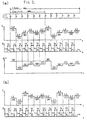
- An electrode unit of a high-pressure discharge lamp has a cathode which emits electrons and an anode which receives electrons emitted from the cathode. Since electrons accelerated by an electric field collide with each other in the anode, the anode is heated to a high temperature and wastes due to evaporation. Since the polarity changes at fixed intervals in an AC high-pressure discharge lamp, a cathode and an anode periodically replace each other. As a result, both the electrodes waste.
- Figure 4(a) shows states of electrode structures 101a and 101b of a general AC high-pressure discharge lamp and an arc discharge A100.
- two electrodes are designed to be of the same shape and the same size such that the electrodes waste uniformly.
- the direction of an AC lamp current switches to the opposite direction when the cycle switches between a positive half cycle and a negative half cycle.
- reference characters 101a denote the cathode during the cycle
- reference characters 101b denote the anode.
- an arc spot appears near K101.
- the direction of the current in the negative half cycle is as indicated by an arrow C2
- reference characters 101b denote the cathode
- reference characters 101a denote the anode.
- An arc spot appears near K102.
- Figure 4(b) shows an example in which, in an AC image projection device, a driving current of a light source is varied such that "the amplitude of red pulses (both positive and negative pulses) is larger than that of blue pulses, and the amplitude of blue pulses is larger than that of green pulses" (see Figure 2b of Patent Document 1 described above).
- a driving current of a light source is varied such that "the amplitude of red pulses (both positive and negative pulses) is larger than that of blue pulses, and the amplitude of blue pulses is larger than that of green pulses” (see Figure 2b of Patent Document 1 described above).
- each color segment and a driving current need to be appropriately synchronized, and the realization is extremely difficult.
- the detailed description of the invention” of Patent Document 1 only describes that "... must operate ... in order that the power in the positive pulses equal the power in the negative pulses", and a specific method for forming a synchronization signal and the like are unclear.
- an AC high-pressure discharge lamp has the essential problem specific to an AC system of a periodic variation in a bright spot position.
- the present invention has been made in consideration of the above, and has as its main object to provide an image projection system which adopts a new synchronization method capable of, even if the magnitude of a driving current is changed for each segment, reliably synchronizing the driving current of a high-pressure discharge lamp and the color segment.
- An image projection system is an image projection system including a DC high-pressure discharge lamp 1, a rotary color filter 3 which separates a light flux ⁇ 1 applied from the high-pressure discharge lamp into a plurality of colors, a reflective optical element 4 which gives gradation to and performs picture signal-based modulation on a light flux ⁇ 2 having passed through the color filter, DC lighting means 5 for driving the high-pressure discharge lamp with a direct current, a projection lens system 6 which projects a light flux ⁇ 3 reflected by the optical element onto a screen, and a synchronization signal generating device 9 which detects rotation of the color filter and generates a synchronization signal S, characterized in that the synchronization signal generating device 9 generates a synchronization signal S composed of a plurality of on-off patterns in synchronism with rotation of the color filter and outputs each of predetermined power levels (e.g., L1 to L4) corresponding one-to-one with the on-off patterns to the high-pressure discharge lamp at fixed timing.
- the on-off patterns of the synchronization signal S (more specifically rectangular pulses Ts1 to Ts4 with different on times) and the power levels (L1 to L4) outputted to the high-pressure discharge lamp are set in advance to correspond one-to-one with each other.
- a power level corresponding to the pattern e.g., L1 for Ts1
- the time for the output is set to be after a lapse of a fixed time T0 from the rising edge of the synchronization signal, it is possible to accurately synchronize rotation of the color filter (i.e., each color segment) and the synchronization signal.
- the maximum value L4 of the power level is set to be not less than 1.1 times the minimum value L1 of the power level.
- electrodes of the high-pressure discharge lamp are configured such that the mass of an anode is preferably set to be larger than that of a cathode. This is because since waste in the anode (evaporation caused by heating) is more likely to occur with an increase in the maximum value (L4) of the power level, the mass of the anode set to be large in advance can make it difficult for the life of a high-pressure discharge lamp to decrease even if the ratio between the maximum value (L4) of the power level and the minimum value (L1) is made large.
- the present invention is defined in claim 1.
- Figure 1 shows an example of a block diagram for explaining the system configuration of an image projection system according to the present invention.
- the system is composed of a light source E made up of a DC high-pressure discharge lamp 1 and a reflector 2, a color filter 3 including a plurality of color segments 3a to 3f, an optical element 4, and a projection lens system 6.
- a light flux ⁇ applied from the high-pressure discharge lamp 1 is directly applied or is reflected by the reflector 2.
- a light flux ⁇ 1 is applied to the color filter 3. After the light flux ⁇ 1 is optically modulated by the optical element 4, a predetermined image pattern is projected onto a screen 7 through the projection lens system 6.
- the color filter 3 includes a plurality of color segments, each of which is composed of a dichroic filter having the property of selectively letting a visible wavelength pass therethrough.
- the color filter 3 in Figure 1 is of six colors of R, G, B, Y, M, and C (red, green, blue, yellow, magenta, and cyan) (3a to 3f).
- the optical element 4 is composed of a reflective digital optical modulator such as a DMD and is a device for reflecting light fluxs ⁇ 2 which have passed through the color segments 3a to 3f and have been separated into respective colors and performing optical modulation using a picture signal (e.g., a video signal) supplied from an optical element driving element 14.
- a reflective digital optical modulator such as a DMD
- a device for reflecting light fluxs ⁇ 2 which have passed through the color segments 3a to 3f and have been separated into respective colors and performing optical modulation using a picture signal (e.g., a video signal) supplied from an optical element driving element 14.
- a DMD is an optical element (optical modulator) for giving gradation to light for each segment having passed through a color filter by giving lightness and performing picture signal-based modulation.
- a DMD is formed by attaching a large number of mirror elements onto a semiconductor memory cell. The inclination of each mirror element is controlled by the optical element driving element 14, and a predetermined pattern can be formed by switching between passing and blocking light in each mirror element.
- DC lighting means 5 incorporates a DC power supply circuit and a controlling circuit which selectively outputs one of a plurality of power levels in accordance with a synchronization signal and is a device which supplies a lamp current for turning on the high-pressure discharge lamp 1. The details of a pattern for a driving current to a high-pressure discharge lamp will be described later.
- the projection lens system 6 is an optical lens for projecting a light flux ⁇ 3 reflected by the surface of the optical element 4 onto the screen (7).
- a color filter driving device 8 is a driving device for rotating the color filter 3 and functions to rotate the color filter 3 at a fixed speed. For example, in the case of a video signal whose frequency for one frame is 60 Hz (a screen changes 60 times per second), the color filter rotates at a speed which is an integral multiple of the frame frequency (e.g., twice, i.e., a frequency of 120 Hz).
- the light flux ⁇ 1 applied from the light source E is subjected to time-division color separation when it passes through the segments 3a to 3f of the color filter 3 rotating at the fixed speed.
- the light fluxs ⁇ 2 separated into the respective colors are launched into the optical element (4) through a light pipe (not shown) or the like.
- the color filter 3 has a positional indicator 3g for detecting timing.
- a photo sensor detects the timing for one rotation of the color filter by sensing the positional indicator 3g and generates a timing reference signal S0.
- the reference signal S0 is inputted to a synchronization signal generating device 9, and a plurality of synchronization signals based on the reference signal S0 in synchronism with the color segments are inputted to the DC lighting means 5.
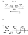
- Figure 2 illustrates, on the same time base, the segment status of a color filter (the top row), a DC lamp current waveform IL (the second row), the waveform of a synchronization signal S (the third row), and the signal strength of the light flux ⁇ 1 applied from the high-pressure discharge lamp 1, in the image projection system according to the present invention.
- Figure 2 shows an example in which a color filter including six segments of R, G, B, Y, M, and C (red, green, blue, yellow, magenta, and cyan) as shown in Figure 1 is rotated at a speed twice a frequency for one frame (one frame: 60 Hz, video field: 120 Hz). Note that although a spoke time may be actually set to absorb effects of the boundary between color segments, a description of transient characteristics will be omitted.
- FIG. 2 An example is shown in Figure 2 in which four types of power levels, L1, L2, L3, and L4, are set in ascending order of power level. On times for the synchronization signal S are identified with Ts1, Ts2, Ts3, and Ts4 in descending order of duration. Any one current strength of the plurality of power levels set in advance is outputted after a lapse of a fixed time T0 from the rising edge of the synchronization signal.
- next driving current IL is set to the level L1 when a pulse width of Ts1 is detected, is set to the level L2 when a pulse width of Ts2 is detected, is set to the level L3 when a pulse width of Ts3 is detected, and is set to the level L4 when a pulse width of Ts4 is detected.
- Ts1 is set to be 100 ⁇ s; Ts2, 150 ⁇ s; Ts3, 200 ⁇ s; Ts4, 250 ⁇ s; and T0, 300 ⁇ s L1, L2, L3, and L4 are set in advance so as to correspond to Ts1 to Ts4.
- the controlling circuit in the synchronization signal generating device 9 adjusts the timing of the synchronization signal, and the DC lighting means 5 need not be changed. Even if the angle of each color segment is changed, if the frame frequency is changed to, e.g., 50 Hz, or if the number of rotations of the color filter is changed, the timing of the synchronization signal only needs to be changed.
- the power levels are associated in ascending order of power level in the following manner:
- the image projection system according to the present invention makes it possible to represent various tints to suit user preferences only by changing patterns of a synchronization signal. Additionally, since change of a circuit and the like of lighting means is unnecessary, the degree of freedom of system design is extremely high.
- a high-pressure discharge lamp serving as a light source uses a DC system, and polarity switching need not be considered, unlike an AC system. It is thus easy to generate a current waveform as described above in a segment next to one when a synchronization signal is received according to the type of the synchronization signal. Note that since symmetry and the like need to be considered, an AC system has many limitations. In contrast, the present system has the advantage of being able to freely arrange the power levels (L1 to L4).
- the number of color segments has been described to be 6 (RGBYMC), and the number of power levels has been described to be 4 (L1 to L4), the numbers are illustrative only. It will be appreciated that the number of segments and the number of power levels can be freely changed by changing the correspondence between a synchronization signal and power levels.
- a high-pressure discharge lamp is driven by a DC system in the present system, an arc spot is fixed in one direction on the cathode side, and a gradation disorder is unlikely to occur.
- superposition of a pulse current on a direct current allows suppression of an arc jump (e.g., Japanese Patent Laid-Open No. 2004-212890 ).
- the waveform of a driving current in the present system is equivalent to that of a direct current with a pulse of the same polarity superposed thereon. Accordingly, if a power level difference (L1 to L4) is set to be not less than a certain level in a video field, the effect of suppressing a flicker caused by an arc jump is expected.
- the effect of suppressing a flicker was experimentally confirmed when, as for the difference between a maximum value (L4) of a power level and a minimum value (L1), the ratio between the maximum value and the minimum value was not less than 1.1.
- FIG 3 shows states of electrode structures 1a and 1b of a general DC high-pressure discharge lamp and an arc discharge A.
- the DC high-pressure discharge lamp illustrated in this embodiment is configured such that the mass of the anode 1b is larger than that of the cathode 1a.
- the ratio between the mass of an anode and that of a cathode for a DC high-pressure discharge lamp of this type is typically about 1.5 to 2.
- a current flows in a direction indicated by an arrow R, and the arc discharge A as in Figure 3 occurs. At this time, a bright spot K appears in the vicinity of the cathode la.
- the mass ratio between the anode and the cathode was set to be a slightly higher value than usual, about 2.5 (2.3 to 2.7).
- a maximum value (L4) of a power level could be set to up to 150% of (1.5 times) a minimum value (L1). This means that a tone adjustable range is wide.
- the level difference is further increased, the anode side may be excessively heated, a tungsten electrode may evaporate, and the life of the discharge lamp may be decreased.
- the vapor pressure of the discharge lamp, the shapes of the electrodes, and the like are optimized, it may be possible to set the level difference to be slightly larger.
- An image projection system is capable of freely supplying different power levels to color segments of a video field, a flicker caused by an arc jump is suppressed, and an arc can be stably maintained.
- the mass of an anode is made larger than that of a cathode, since the level difference between a maximum value of a power level and a minimum value can be set to up to, e.g., about 150%, a range within which a tone can be changed to suit user preferences is wide. Since a DC system is used, a spot position does not vary, and no error occurs in a light flux ( ⁇ ) applied to a color filter for each video field. Accordingly, it is possible to continue to output a stable light flux.
Claims (3)
- Bildprojektionssystem, mit einer Gleichspannungs-Entladungslampe (1) mit hoher Intensität, einem Drehfarbfilter (3), der einen Lichtfluss (φ1), der von der Hochdruck-Entladungslampe eingegeben wird, in mehrere Farben trennt, einem reflektierenden optischen Element (4), das eine Abstufung erzeugt und eine Modulation auf Bildsignalbasis an einem Lichtfluss (φ2), der sich durch den Farbfilter bewegt hat, ausführt, Gleichspannungs-Beleuchtungsmitteln (5), um die Hochdruck-Entladungslampe mit einem Gleichstrom anzusteuern, einem Projektionslinsensystem (6), das einen Lichtfluss (φ3), der durch das optische Element reflektiert wird, auf einen Schirm projiziert, und einer Synchronisationssignal-Erzeugungsvorrichtung (9), die eine Drehung des Farbfilters detektiert und ein Synchronisationssignal (S) erzeugt,
dadurch gekennzeichnet, dass die Synchronisationssignal-Erzeugungsvorrichtung (9) dafür ausgelegt ist, ein Synchronisationssignal (S), das aus mehreren Ein/Aus-Mustern von Rechteckimpulsen mit unterschiedlichen Einschaltzeiten aufgebaut ist, synchron mit der Drehung des Farbfilters zu erzeugen und jeweils vorgegebene Leistungspegel (z. B. L1 bis L4), die Eins-zu-Eins den Ein/Aus-Mustern entsprechen, zu der Hochdruck-Entladungslampe mit fester Zeitvorgabe für das nächste Farbsegment des Drehfarbfilters (3) auszugeben. - Bildprojektionssystem nach Anspruch 1, dadurch gekennzeichnet, dass ein Maximalwert (L4) der Leistungspegel so eingestellt ist, dass er nicht kleiner als der 1,1-fache Minimalwert (L1) der Leistungspegel ist.
- Bildprojektionssystem nach Anspruch 1, dadurch gekennzeichnet, dass Elektroden der Hochdruck-Entladungslampe in der Weise konfiguriert sind, dass eine Anode eine größere Masse besitzt als eine Katode.
Applications Claiming Priority (1)
| Application Number | Priority Date | Filing Date | Title |
|---|---|---|---|
| PCT/JP2006/319354 WO2008038382A1 (fr) | 2006-09-28 | 2006-09-28 | Système de projection d'image au moyen d'une lampe à décharge haute tension de type courant continu |
Publications (3)
| Publication Number | Publication Date |
|---|---|
| EP2065877A1 EP2065877A1 (de) | 2009-06-03 |
| EP2065877A4 EP2065877A4 (de) | 2010-01-20 |
| EP2065877B1 true EP2065877B1 (de) | 2012-12-05 |
Family
ID=39229830
Family Applications (1)
| Application Number | Title | Priority Date | Filing Date |
|---|---|---|---|
| EP06798402A Expired - Fee Related EP2065877B1 (de) | 2006-09-28 | 2006-09-28 | Bildprojektionssystem mittels einer hochspannungsentladungslampe des gleichstromtyps |
Country Status (3)
| Country | Link |
|---|---|
| US (1) | US20100026726A1 (de) |
| EP (1) | EP2065877B1 (de) |
| WO (1) | WO2008038382A1 (de) |
Families Citing this family (12)
| Publication number | Priority date | Publication date | Assignee | Title |
|---|---|---|---|---|
| SE523855C2 (sv) | 2000-11-10 | 2004-05-25 | Alfa Laval Corp Ab | Järnbaserat lodmaterial för sammanfogning av elememt och lödd produkt framställd härmed |
| CN101454719B (zh) * | 2006-05-29 | 2010-06-23 | 松下电器产业株式会社 | 投射型显示装置 |
| JP2009288349A (ja) * | 2008-05-27 | 2009-12-10 | Panasonic Electric Works Co Ltd | 放電灯点灯装置およびそれを用いる画像表示装置 |
| US9165756B2 (en) | 2011-06-08 | 2015-10-20 | Xenex Disinfection Services, Llc | Ultraviolet discharge lamp apparatuses with one or more reflectors |
| US9093258B2 (en) | 2011-06-08 | 2015-07-28 | Xenex Disinfection Services, Llc | Ultraviolet discharge lamp apparatuses having optical filters which attenuate visible light |
| US9114182B2 (en) | 2012-02-28 | 2015-08-25 | Xenex Disinfection Services, Llc | Germicidal systems and apparatuses having hollow tumbling chambers |
| CN103375773A (zh) * | 2012-04-12 | 2013-10-30 | 鼎众股份有限公司 | 手术灯的色温调整装置 |
| AU2012396233B2 (en) | 2012-12-06 | 2017-09-28 | Xenex Disinfection Services, Llc | Systems which determine operating parameters and disinfection schedules for germicidal devices and germicidal lamp apparatuses including lens systems |
| US8816301B2 (en) | 2012-12-07 | 2014-08-26 | Xenex Healthcare Services, Llc | Lamp and reflector arrangements for apparatuses with multiple germicidal lamps |
| JP2016045346A (ja) * | 2014-08-22 | 2016-04-04 | 株式会社リコー | 画像投射装置 |
| US9517284B1 (en) | 2015-07-02 | 2016-12-13 | Xenex Disinfection Services, Llc. | Germicidal apparatuses with configurations to selectively conduct different disinfection modes interior and exterior to the apparatus |
| US9867894B2 (en) | 2015-07-02 | 2018-01-16 | Xenex Disinfection Services, Llc. | Germicidal apparatuses with configurations to selectively conduct different disinfection modes interior and exterior to the apparatus |
Family Cites Families (13)
| Publication number | Priority date | Publication date | Assignee | Title |
|---|---|---|---|---|
| JPH05113604A (ja) * | 1991-10-22 | 1993-05-07 | Sony Corp | プロジエクタ装置 |
| US5479065A (en) * | 1992-12-28 | 1995-12-26 | Toshiba Lighting & Technology Corporation | Metal halide discharge lamp suitable for an optical light source having a bromine to halogen ratio of 60-90%, a wall load substantially greater than 40 W/cm2, and a D.C. potential between the anode and cathode |
| EP0676115B1 (de) | 1993-10-21 | 2000-06-07 | Koninklijke Philips Electronics N.V. | Bildprojektionsvorrichtung und lampensteuerungssystem zur verwendung darin |
| JPH07225364A (ja) * | 1994-02-15 | 1995-08-22 | Mitsubishi Heavy Ind Ltd | 液晶ディスプレイ装置 |
| US6002452A (en) * | 1995-06-08 | 1999-12-14 | Texas Instruments Incorporated | Sequential color display system with spoke synchronous frame rate conversion |
| DE19714008A1 (de) * | 1997-04-04 | 1998-10-08 | Patent Treuhand Ges Fuer Elektrische Gluehlampen Mbh | Gleichstrombogenlampe |
| JP3899641B2 (ja) * | 1998-02-24 | 2007-03-28 | 株式会社富士通ゼネラル | 反射型プロジェクタ |
| DE10048759A1 (de) * | 2000-09-29 | 2002-04-11 | Aixtron Gmbh | Verfahren und Vorrichtung zum Abscheiden insbesondere organischer Schichten im Wege der OVPD |
| US6520648B2 (en) * | 2001-02-06 | 2003-02-18 | Infocus Corporation | Lamp power pulse modulation in color sequential projection displays |
| JP2005049362A (ja) * | 2001-06-04 | 2005-02-24 | Matsushita Electric Ind Co Ltd | 液晶表示装置 |
| JP2004212890A (ja) | 2003-01-08 | 2004-07-29 | Phoenix Denki Kk | 投射型システムとその作動方法 |
| KR100629534B1 (ko) * | 2004-02-12 | 2006-09-27 | 엘지전자 주식회사 | 온도변화에 따른 색오차 보정방법 및 장치 |
| US7623286B2 (en) * | 2006-02-24 | 2009-11-24 | Texas Instruments Incorporated | System and method for displaying images |
-
2006
- 2006-09-28 WO PCT/JP2006/319354 patent/WO2008038382A1/ja active Application Filing
- 2006-09-28 US US12/443,205 patent/US20100026726A1/en not_active Abandoned
- 2006-09-28 EP EP06798402A patent/EP2065877B1/de not_active Expired - Fee Related
Also Published As
| Publication number | Publication date |
|---|---|
| EP2065877A1 (de) | 2009-06-03 |
| EP2065877A4 (de) | 2010-01-20 |
| US20100026726A1 (en) | 2010-02-04 |
| WO2008038382A1 (fr) | 2008-04-03 |
Similar Documents
| Publication | Publication Date | Title |
|---|---|---|
| EP2065877B1 (de) | Bildprojektionssystem mittels einer hochspannungsentladungslampe des gleichstromtyps | |
| CN101263747B (zh) | 用于操作高强度放电灯的方法、灯驱动器以及投影系统 | |
| US8044602B2 (en) | Method of driving discharge lamp, driving device, and projector | |
| CN102301828B (zh) | 用于驱动气体放电灯的方法和电子驱动设备以及投影器 | |
| US8591041B2 (en) | Method for driving a high-pressure gas discharge lamp of a projector system | |
| WO2006088965A2 (en) | System and method for increasing bit-depth in a video display system using a pulsed lamp | |
| JP2004212890A (ja) | 投射型システムとその作動方法 | |
| JP2009237302A (ja) | 画像投影装置、プロジェクタ用の光源点灯装置 | |
| US8461772B2 (en) | High pressure discharge lamp ballast and light source apparatus | |
| JP4397870B2 (ja) | 直流方式の高圧放電灯による画像投射システム | |
| EP3102006B1 (de) | Entladungslampenansteuerungsvorrichtung, lichtquellenvorrichtung, projektor und entladungslampenansteuerungsverfahren | |
| US7517093B2 (en) | Projection-type system and method of operating the same | |
| CN102301829A (zh) | 用于驱动气体放电灯的方法和电子驱动设备以及投影器 | |
| US20100134765A1 (en) | Method of driving a discharge lamp in a projection system, and driving unit | |
| JP2009048019A (ja) | 画像投影装置、及び画像投影装置の調光制御方法 | |
| JP2007047234A (ja) | 直流点灯の高圧放電灯による投射型システム | |
| JP2008116781A (ja) | 画像投射システム | |
| JP2007155952A (ja) | 高圧放電灯による投射型システム | |
| US8143802B2 (en) | Method of driving discharge lamp, driving device, and projector |
Legal Events
| Date | Code | Title | Description |
|---|---|---|---|
| PUAI | Public reference made under article 153(3) epc to a published international application that has entered the european phase |
Free format text: ORIGINAL CODE: 0009012 |
|
| 17P | Request for examination filed |
Effective date: 20090331 |
|
| AK | Designated contracting states |
Kind code of ref document: A1 Designated state(s): DE FR GB |
|
| AX | Request for extension of the european patent |
Extension state: AL BA HR MK RS |
|
| A4 | Supplementary search report drawn up and despatched |
Effective date: 20091222 |
|
| 17Q | First examination report despatched |
Effective date: 20100322 |
|
| REG | Reference to a national code |
Ref country code: DE Ref legal event code: R079 Ref document number: 602006033502 Country of ref document: DE Free format text: PREVIOUS MAIN CLASS: G09G0003340000 Ipc: G09G0003000000 |
|
| RIC1 | Information provided on ipc code assigned before grant |
Ipc: G09G 3/00 20060101AFI20111229BHEP |
|
| GRAP | Despatch of communication of intention to grant a patent |
Free format text: ORIGINAL CODE: EPIDOSNIGR1 |
|
| DAX | Request for extension of the european patent (deleted) | ||
| GRAS | Grant fee paid |
Free format text: ORIGINAL CODE: EPIDOSNIGR3 |
|
| RAP1 | Party data changed (applicant data changed or rights of an application transferred) |
Owner name: PHOENIX ELECTRIC CO., LTD. |
|
| GRAA | (expected) grant |
Free format text: ORIGINAL CODE: 0009210 |
|
| AK | Designated contracting states |
Kind code of ref document: B1 Designated state(s): DE FR GB |
|
| REG | Reference to a national code |
Ref country code: GB Ref legal event code: FG4D |
|
| RIN1 | Information on inventor provided before grant (corrected) |
Inventor name: NAKAGAWA, ATSUJI Inventor name: FUJII, TOSHITAKA |
|
| REG | Reference to a national code |
Ref country code: DE Ref legal event code: R096 Ref document number: 602006033502 Country of ref document: DE Effective date: 20130124 |
|
| PLBE | No opposition filed within time limit |
Free format text: ORIGINAL CODE: 0009261 |
|
| STAA | Information on the status of an ep patent application or granted ep patent |
Free format text: STATUS: NO OPPOSITION FILED WITHIN TIME LIMIT |
|
| PGFP | Annual fee paid to national office [announced via postgrant information from national office to epo] |
Ref country code: DE Payment date: 20130925 Year of fee payment: 8 |
|
| 26N | No opposition filed |
Effective date: 20130906 |
|
| REG | Reference to a national code |
Ref country code: DE Ref legal event code: R097 Ref document number: 602006033502 Country of ref document: DE Effective date: 20130906 |
|
| GBPC | Gb: european patent ceased through non-payment of renewal fee |
Effective date: 20130928 |
|
| REG | Reference to a national code |
Ref country code: FR Ref legal event code: ST Effective date: 20140530 |
|
| PG25 | Lapsed in a contracting state [announced via postgrant information from national office to epo] |
Ref country code: GB Free format text: LAPSE BECAUSE OF NON-PAYMENT OF DUE FEES Effective date: 20130928 |
|
| PG25 | Lapsed in a contracting state [announced via postgrant information from national office to epo] |
Ref country code: FR Free format text: LAPSE BECAUSE OF NON-PAYMENT OF DUE FEES Effective date: 20130930 |
|
| REG | Reference to a national code |
Ref country code: DE Ref legal event code: R119 Ref document number: 602006033502 Country of ref document: DE |
|
| PG25 | Lapsed in a contracting state [announced via postgrant information from national office to epo] |
Ref country code: DE Free format text: LAPSE BECAUSE OF NON-PAYMENT OF DUE FEES Effective date: 20150401 |