EP2065150A1 - A device for making continuous veining of desired patterns extending through the entire thickness of a product and process of making thereof - Google Patents
A device for making continuous veining of desired patterns extending through the entire thickness of a product and process of making thereof Download PDFInfo
- Publication number
- EP2065150A1 EP2065150A1 EP07450217A EP07450217A EP2065150A1 EP 2065150 A1 EP2065150 A1 EP 2065150A1 EP 07450217 A EP07450217 A EP 07450217A EP 07450217 A EP07450217 A EP 07450217A EP 2065150 A1 EP2065150 A1 EP 2065150A1
- Authority
- EP
- European Patent Office
- Prior art keywords
- distributing
- materials
- cartridge
- tray
- material receiving
- Prior art date
- Legal status (The legal status is an assumption and is not a legal conclusion. Google has not performed a legal analysis and makes no representation as to the accuracy of the status listed.)
- Granted
Links
Images


Classifications
-
- B—PERFORMING OPERATIONS; TRANSPORTING
- B28—WORKING CEMENT, CLAY, OR STONE
- B28B—SHAPING CLAY OR OTHER CERAMIC COMPOSITIONS; SHAPING SLAG; SHAPING MIXTURES CONTAINING CEMENTITIOUS MATERIAL, e.g. PLASTER
- B28B13/00—Feeding the unshaped material to moulds or apparatus for producing shaped articles; Discharging shaped articles from such moulds or apparatus
- B28B13/02—Feeding the unshaped material to moulds or apparatus for producing shaped articles
- B28B13/0215—Feeding the moulding material in measured quantities from a container or silo
- B28B13/022—Feeding several successive layers, optionally of different materials
-
- B—PERFORMING OPERATIONS; TRANSPORTING
- B28—WORKING CEMENT, CLAY, OR STONE
- B28B—SHAPING CLAY OR OTHER CERAMIC COMPOSITIONS; SHAPING SLAG; SHAPING MIXTURES CONTAINING CEMENTITIOUS MATERIAL, e.g. PLASTER
- B28B1/00—Producing shaped prefabricated articles from the material
- B28B1/005—Devices or processes for obtaining articles having a marble appearance
Definitions
- System S.p.A. an Italian machinery manufacturer, developed a tile forming press for a large format, capable of producing ceramic tiles of up to 3 meters in length.
- System S.p.A. has detailed its technique for making patterns throughout the mass of the ceramic tiles in EP 1334811 .
- the technique is characterized by a double-pressing that comprises first a low pressure compacting.
- the compacted ceramic tiles are subsequently decorated by an ink-jet system to apply, according to the design, special ceramic colors which can penetrate into the tile mass.
- appearance of the patterns in the tile mass is somewhat partial and the level of depth of pattern penetration is not deep enough to provide the pattern to the lowest layer of the tile mass.
- a pattern regulating sensor (80) is also provided.
- the pattern regulating sensor (80) (“the sensor") is positioned such that it can scan the pattern forming inside the vertical material receiving-distributing cartridge (30) to read the pattern values (pre-coded values which are predetermined in order to produce a desired pattern). More preferably, it is positioned above the vertical material receiving-distributing cartridge (30).
- the sensor (80) is linked to the software application which records pre-coded values of the desired pattern which in turn control the operation mechanism of the material distributing control cartridge (10) as well as the material distributing tray (60).
- the vertical material receiving-distributing unit (30) is configured such that at least one of its sidewalls, preferably the sidewall with large surface area, is able to move in a loop, similar to a conveyer.
- the moveable sidewall is set to drive in the same direction with the movement of the materials discharging from the vertical material receiving-distributing cartridge (30). If tiles or slabs with greater thickness are desired, it is desirable to provide the vertical material receiving-distributing cartridge (30) with two opposing movable walls.
- the movable sidewall helps to reduce friction between the material granules and the wall surface, thus discharging the patterned materials onto the conveyer belt (40) is easier and with minimal dispersion of patterned materials. Thus, the formed pattern is maintained. Accordingly, with the use of the vertical material receiving-distributing cartridge (30) having movable sidewalls, a 90-degree turn of the material receiving unit is no longer necessary. Consequently, irregularities or damages to the pattern are reduced.
- the process for making continuous veining of desired patterns extending throughout the entire thickness of the products according to the invention comprises the following three main stages:
- the predetermined materials on the arrangement belt (20) After the predetermined materials on the arrangement belt (20) have moved to the farthest position of the arrangement belt (20), those materials fall into the vertical material receiving-distributing cartridge (30) through the first opening (32) which remains open. The process is repeated.
- the materials inside the vertical material receiving-distributing cartridge (30) are formed in such a manner that one layer is placed over another in accordance with the pattern, the quantity of the materials, and the position at which the predetermined patterns is created.
- the patterned materials on the conveyor belts (40) move forward to the horizontal material receiving-distributing cartridge (50) through the first exit (52). After the patterned materials move completely inside the cover sheet (51), the open-close member (54) is closed down. Then the horizontal material receiving-distributing cartridge (50) will move forward to bring the patterned materials to the pressing machine.
- the pressing sheet (56) moves down to lay flat against the upper surface of the patterned materials while the patterned materials are moving towards the pressing machine so that the powdery materials around the areas are saved from dispersion which damages the surface patterns. While the horizontal material receiving-distributing cartridge (50) is moving, the conveyor belt (40) also moves in order to prevent damage to the lower layer of the patterns.
Landscapes
- Engineering & Computer Science (AREA)
- Manufacturing & Machinery (AREA)
- Chemical & Material Sciences (AREA)
- Ceramic Engineering (AREA)
- Mechanical Engineering (AREA)
- Devices For Post-Treatments, Processing, Supply, Discharge, And Other Processes (AREA)
Abstract
Description
- This invention relates to mechanical, electrical, and electronics engineering, more specifically, a device for making a continuous veining of desired pattern in a ceramic tile using powdery or granular material as described in the preamble of claim 1, as well as a corresponding method.
- Research in the ceramic tile production sector is currently aimed at obtaining tiles that closely resemble natural stones by using many different technologies. Natural stones, such as marble, sandstones, and other kinds of stones, possess a natural beauty that is highly appreciated by consumers. Not only does the production of ceramic tiles for achieving the resemblance of natural stones have benefits in terms of beauty, but also it is advantageous in terms of properties of hardness and durability, technically much better than natural stones. The traditional art relating to techniques of the production of patterned ceramic tiles involved only a thin layer on the surface of the tiles, such as pattern printings, depositing desired patterns before or after pressing by using either wet or dry powder application method. In the described traditional techniques, the desired patterns only appear on the surface of the tiles. However, abrasion from weathering and use cause deterioration on the surface of the desired patterned ceramic tiles, which results in deviations from the original pattern. Due to this limitation of the techniques that patterns appear only on the surface of the tiles, there are considerable requirements for technological development of the production of ceramic tiles, enabling the tiles to possess a continuous veining of desired pattern extending through their entire thickness. Typical examples of said development are referred to hereinafter.
- System S.p.A., an Italian machinery manufacturer, developed a tile forming press for a large format, capable of producing ceramic tiles of up to 3 meters in length. System S.p.A. has detailed its technique for making patterns throughout the mass of the ceramic tiles in
EP 1334811 . The technique is characterized by a double-pressing that comprises first a low pressure compacting. The compacted ceramic tiles are subsequently decorated by an ink-jet system to apply, according to the design, special ceramic colors which can penetrate into the tile mass. By this technique, however, appearance of the patterns in the tile mass is somewhat partial and the level of depth of pattern penetration is not deep enough to provide the pattern to the lowest layer of the tile mass. - CMF S.r.1 of Italy has introduced a technique of filling tubes with a mixture of powdery materials of different characteristics and then distributing the powdery materials through openings which are of two sizes, small and large. The powder distribution technique creates a continuous veining of patterns stored in a compartment which is in a position perpendicular to the plane. Once the powdery materials are fully filled and arranged in layers of the continuous veining of patterns inside the compartment, the compartment is rotated 90 degrees in order to lie parallel to the plane. The powdery materials in the desired patterns are then transferred into the mold. From this technique, the transfer of powdery materials into the mold is also problematic. It has been found that the powder mass is mixed on the tile surface, requiring the ceramic tiles to be polished after firing in order to obtain the visible veining effect of the patterns. A still further disadvantage of the technique is that the veining pattern is not continuous and appears to zigzag. Since the tubes used for holding materials have openings on only two sizes, it is impossible to control the quantity of the material relative to the changes either in dimension or width of the veining patterns.
- Sacmi of Italy, the world's leading machinery company in the ceramic tile industry, has tried to develop a technique to make continuous veining of patterns extending through the entire thickness of tiles or slabs, as mentioned in
EP 1273408 andWO 2004/071733 . However, there remains the possibility that materials on the surface layer have been mixed, causing the desired pattern to be distorted. There has been, therefore, a necessity to remove those mixed materials at the surface layer by suction before pressing in order to obtain patterns that are visible without having to polish the upper surfaces of ceramic tiles after firing. - This application is a development of
EP 1717 000 A1 . The device according to the mentioned European application comprises a material distributing control cartridge which consists of multiple tubes which act as a container for holding the powder or granulated materials for making the tiles. All of the tubes are fixed but movable reciprocally on an axle having the course of movement on the horizontal direction, perpendicular to the movement direction of the arrangement belt. The materials are then released through open-closed valves fitted at the end of the tubes on the arrangement belt and subsequently into the vertical material receiving-distributing cartridge to form the desired pattern. Once the vertical material receiving-distributing cartridge is filled, the vertical material receiving-distributing cartridge is rotated 90 degrees to horizontally discharge the patterned materials onto the conveyer belts. The discharged patterned materials are then guide-fed into the horizontal material receiving-distributing unit bringing the patterned materials toward the pressing station to press the patterned materials into a tile. - The disadvantages of the mentioned prior application were the fact that the tubes are fixed and the materials are released from the open-closed valves which are fixed to said tubes, which limits the patterns produced thereby. In addition, in the prior application, the amount of different colors and different characteristics of the materials are controlled-released using the valves, thus making it very time consuming for the materials to fill the vertical materials receiving-distributing cartridge. Consequently, the production volume is very low. Further, there are still irregularities in the pattern once the patterned materials were transferred from the vertical material receiving-distributing cartridge onto the conveyer belt. Therefore, further improvement to the device is needed.
- The present invention relates to a device and a process of making continuous veining of desired patterns extending through the entire thickness of the products from powdery materials or granulated powders employing a device developed therefor. The powdery materials or granulated powders can be either organic or inorganic substances which possess a continuous and uniform flow. The process is to bring about the continuous veining of desired patterns by varying the width of veining of patterns which can be done continuously, smoothly, and successfully without appreciable mixing of the powdery materials of different colors at the surface layer of the products. Therefore, the products obtained from this process are well defined and meet with the desired patterns. However, if desired, the product may objectively be subjected to further beautifying or decorating processes to enhance the beauty or value of the product.
- The invention is an improved process and device for making patterns from powdery materials or granulated powders which have the quality of a continuous flow in order to bring about the making of continuous veining of patterns extending through the entire thickness of products in a desired format and to be able to adjust or change the patterns easily during production. The invention aims to obviate the limitations of the pattern created by the materials distributing control cartridge and drawbacks of irregularities of the pattern while transferring the patterned material from the vertical.
- This aim is achieved by a device and a corresponding method according to the present invention as described in the dependent claims.
- The characteristics and outstanding features of the invention as described above will become more apparent from the discussion of a nonrestrictive preferred embodiment of the invention which is illustrated in the attached figures.
-
Figure 1 shows an overall view of an embodiment of the present invention, including the material distributing control cartridge (10), the material distributing tray (60), the arrangement belt (20), the vertical material receiving-distributing cartridge (30), the conveyer belt (40), and the horizontal receiving-distributing cartridge (50); -
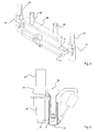
Figure 2 shows a perspective view of the material distributing control cartridge (10) indicating its ability to move in multi directions; -
Figure 3 shows a perspective view of the material distributing tray (60); -
Figure 4 shows a side view of the material distributing tray (60); -
Figure 5 shows an operation of the material distributing tray (60), the arrangement belt (20), and the vertical material receiving-distributing cartridge (30); -
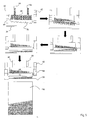
Figure 6 shows an example of the formation of the pattern and the relationship of the material distribution tray (60), the sensor (80), the arrangement belt (20), the vertical material receiving-distributing cartridge (30), and the conveyer belt (40); -
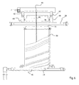
Figure 7 shows a side view of the configuration and mechanism of the vertical material receiving-distributing cartridge (30); -
Figure 8 shows the operation of the vertical material receiving-distributing cartridge (30), the conveyer belt (40) ,and the horizontal receiving-distributing cartridge (50) inside of which the materials are contained until full moving toward a pressing unit; -
Figure 9 shows a side view detail of the horizontal material receiving-distributing cartridge (50). - According to one exemplary embodiment, as shown in
Fig. 1 , the device and method for making continuous veining of patterns throughout the entire thickness of the products comprises a material distributing control cartridge (10) which is installed to be driven with reciprocating motion above an arrangement belt (20), a vertical material receiving-distributing cartridge (30) which is installed at the farthest end position of and under the arrangement belt (20), but situated above a conveyor belt (40), and a horizontal material receiving-distributing cartridge (50) which is installed on the conveyor belt (40). A detailed description of the apparatus follows: - The material distributing control cartridge (10) consists of more than one tube (12), which are containers for holding the material of different characteristics and different colors. There can be more than one tube (12) depending on the different characteristics and different colors of the materials used. The material distributing control cartridge is capable of moving in multi-directions as shown in
Fig. 2 . All of the tubes (12) are movable reciprocally on an axle (14) (support beam) that is able to rotate in multi-directions, having the course of movement perpendicular to the movement direction of the arrangement belt (20). Open-close valves (16) are located at the end of each tube (12). The fact that the material distributing control cartridge (10) is able to rotate will increase the range of pattern as the tubes (12) will now be able to form veins with curved, circular, diagonal, or free-form characters. The material distributing control cartridge (10) is further equipped with a material distributing tray (60). - Within this disclosure, the term "open-close" is meant to describe devices which can be controlled (switched) between an open and closed state, such as a shutter. An open-close means will open or close in accordance with the stored data, i.e., in response to the control program.
- Referring to
Figs. 3 and 4 , the material distributing tray (60) is located away from (i.e., at a distance to) the tubes (12) but above the arrangement belts (20) as with the tubes (12). The material distributing tray (60) is situated between two arms (62) of an axle (not shown). Each arm (62) has an outer sleeve (64) which is capable of moving up and down along the arm (62) and relative to the arrangement belt (20). The material distributing tray (60) is capable of holding a large quantity of the materials released from a plurality of delivering means (66) similar to the tubes (12) of the material distributing control cartridge (10), but preferably larger in size. The material distributing tray (60) comprises a first tray (68) and a second tray (70), wherein the first tray (68) is situated on top, i.e., farther above relative to the second tray (70) while its bottom region is situated within the top portion of the second tray (70). The bottom of both the first tray (68) and the second tray (70) has an open-closed flap (72, 73). The second tray (70) is connected to the sleeves (64) of the arms (62) by joint members (74) enabling to second tray (70) to move up or down along the arm (62). Preferably, the sleeves (64) of the arms (62) are capable of moving up and down along the arms (62) such that the height of the second tray (70) can be altered relative to the arrangement belt (20) so as to bring the second tray (70) closer to or further away from the arrangement belt (20). The movement of each of the sleeves (64) can be adjusted independently from each other as required allowing the second tray (70) to move closer to or further away from the arrangement belt (20) and/or to be positioned level and/or tilted left or right as required. - Referring again to
Fig. 1 , a pattern regulating sensor (80) is also provided. Preferably, the pattern regulating sensor (80) ("the sensor") is positioned such that it can scan the pattern forming inside the vertical material receiving-distributing cartridge (30) to read the pattern values (pre-coded values which are predetermined in order to produce a desired pattern). More preferably, it is positioned above the vertical material receiving-distributing cartridge (30). The sensor (80) is linked to the software application which records pre-coded values of the desired pattern which in turn control the operation mechanism of the material distributing control cartridge (10) as well as the material distributing tray (60). In general, the material distributing control cartridge (10) as well as the material distributing tray (60) dispense the materials in accordance with the pre-coded values to form the desired pattern. However, deviation of the pattern may be experienced due to inconsistency of factors such as flow rate of the materials, amount of material being dispensed, the degree of tilting of the second tray (70), etc. Accordingly, once the materials are layered inside the vertical material receiving-distributing cartridge (30), the sensor (80) would scan for values, for example, the slope, or curve values of the pattern being formed against the set values. If discrepancies are detected, the sensor (80) will transmit the information to the control unit which will cause the material distributing control cartridge (10) and/or the material distributing tray (60) to recalibrate to bring the values back to the set values. -
Fig. 6 shows an example of the pattern being formed inside the vertical material receiving-distributing cartridge (30) which is made of layers of various sizes of curvy sloped veins arranged in an alternating manner. If the value of the slope detected by the sensor (80) does not match with the set value, the sensor (80) will send the detected value to the control unit to recalibrate or adjust the degree of tilting of the second tray (70) accordingly to meet the set value. The degree of tilting should always correspond to the pre-coded values of the desired pattern design as well as the slope of the last batch of materials forming a pattern inside the vertical material receiving-distributing cartridge (30). This feature will ensure the consistency of the pattern. - As mentioned, the present invention further comprises the material distributing tray (60). The material distributing tray (60) will shorten the time required for the materials to fill the vertical material receiving-distributing cartridge (30), in comparison to the device with a material distributing control cartridge (10) alone and without the material distributing tray (60) because the material distributing tray (60) will be able to dispense a load faster and with larger quantity of the material onto the arrangement belt (20). Thus, production volume over time is higher. The feature of having material distributing tray (60) is also particularly useful when a pattern with one single color and/or characteristic of large area of single color alternated with smaller vein(s) of color(s) is desired. The material distributing tray (60) may be located before or after the material control cartridge (10).
- Referring to
Figs. 6 and7 , the vertical material receiving-distributing cartridge (30) is a flat rectangular box installed under the farthest end position of the movement of the arrangement belt (20) but situated above the conveyor belt (40) by being placed perpendicular to both the arrangement belt (20) and the conveyor belt (40), as well as perpendicular to movement directions of both belts. This vertical material receiving-distributing unit (30) has two connected ridges forming first opening (32) and second opening (34). The mouth of first opening (32) is formed into a slant lip wherein its upper part is wider than its lower part so as to facilitate receiving of the materials from the arrangement belt (20). The mouth of the second opening (34) also has a lip slightly bent forward to allow that the material easily glides onto the conveyer belt (40). In the present invention, the vertical material receiving-distributing unit (30) is configured such that at least one of its sidewalls, preferably the sidewall with large surface area, is able to move in a loop, similar to a conveyer. The moveable sidewall is set to drive in the same direction with the movement of the materials discharging from the vertical material receiving-distributing cartridge (30). If tiles or slabs with greater thickness are desired, it is desirable to provide the vertical material receiving-distributing cartridge (30) with two opposing movable walls. The movable sidewall helps to reduce friction between the material granules and the wall surface, thus discharging the patterned materials onto the conveyer belt (40) is easier and with minimal dispersion of patterned materials. Thus, the formed pattern is maintained. Accordingly, with the use of the vertical material receiving-distributing cartridge (30) having movable sidewalls, a 90-degree turn of the material receiving unit is no longer necessary. Consequently, irregularities or damages to the pattern are reduced. - Referring to
Figs. 8 and 9 , the horizontal material receiving-distributing cartridge (50) consists of a flat rectangular cover sheet (51) with two ridges on opposite sides forming first exit (52) and second exit (53). An open-close member (54) is positioned at the mouth of the first exit (52), while an open-close and excess material removal flap (55) is positioned at the second exit (53). Inside the cover sheet (51), a pressing sheet (56) is positioned. The horizontal material receiving-distributing cartridge (50) is laid prone on the conveyor belt (40). The direction of the in-and-out path of materials from the horizontal material receiving-distributing cartridge (50) is the same as the movement direction of the conveyor belt (40). - The process for making continuous veining of desired patterns extending throughout the entire thickness of the products according to the invention comprises the following three main stages:
- First Stage. Distributing the materials onto the arrangement belt (20). The materials are to be distributed from the tubes (12) as well as from the material distributing tray (60) onto the arrangement belt (20) which is moving forward in order to control a succession of materials, the quantity of the material, and the position at which the materials are released onto the vertical material receiving-distributing cartridge (30) in accordance with the predetermined patterns. Preferably, the materials distributed from the tubes (12) are for producing smaller veins or finer patterns while the materials distributed from the material distributing tray (60) will form larger veins wherein alternation of small with large veins forms into a desired pattern. The apparatus which control the work in this procedure are the material distributing control cartridge (10), the material distributing tray (60), and the arrangement belt (20).
- Second Stage. Allowing the material which is already distributed onto the arrangement belt (20) to flow into the vertical material receiving-distributing cartridge (30) to bring about the patterns. The materials will be allowed to fall down in such a manner as to form layered patterns inside the vertical material receiving-distributing cartridge (30) in accordance with the predetermined patterns, quantity, and position of the materials to form the desired patterns. From then on, the movable sidewalls will activate and drive the materials which have formed into the desired pattern inside the vertical material receiving-distributing cartridge (30) through the second opening (34) transferring the patterned materials onto the conveyor belt (40) which will move forward in order to transfer said materials from the vertical material receiving-distributing cartridge (30). The apparatus which control the work in this procedure are the vertical material receiving-distributing cartridge (30), the arrangement belt (20), and the conveyor belt (40).
- Third Stage. Relocating the patterned materials from the conveyor belt (40) to the pressing machine by having the cover sheet (51) protect against damage to the patterns during the relocation. The apparatus which control the work in this procedure are the horizontal material receiving-distributing cartridge (50) and the conveyor belt (40).
- The work starts from the material distributing control cartridge (10) in combination with the material distributing tray (60) which performs the duty of distributing the materials onto the arrangement belt (20) in accordance with the predetermined patterns, quantity, and position of the materials. The material which will form smaller veins or finer patterns will be distributed through the operation of the open-close valves (16) of the tubes (12). The open-close valves (16) control the distribution and the quantity of the materials while the tubes (12) are moving in the reciprocating motion on the axle (14). The movement of the arrangement belt (20) determines the position at which the materials will be distributed. The material which will form larger veins or chunky patterns will be distributed by the operation of the material distributing tray (60). As shown in
Fig. 5 , the materials are fed into the first tray (68); at this stage the open-close flap (72) at the bottom of the first tray (68) is in a closed state. Thereafter, the open-closed flap (72) at the bottom of the first tray (68) will open and discharge a specified amount of the materials into the second tray (70) while the open-close flap (73) at the bottom of the second tray (70) is in a closed state. As disclosed, the materials are being dispensed from the material distributing control cartridge (10) and the material distributing tray (60) in accordance with the pre-coded values. If the desired pattern involves veins of material arranged in slopes as shown inFig. 5 , the value of the slope will be pre-coded in the software application. The pre-coded slope values will correlate with the degree of tilting of the second tray (while in production, the sensor (80) will simultaneously detect the slope value of the material inside the vertical material receiving-distributing cartridge (30) as shown inFig. 6 ). The detected value is checked against the set value. If there is discrepancy, the control unit will recalibrate and cause the second tray (70) to tilt to the determined value to maintain the desired pattern. This is to ensure the consistency of the pattern. The materials are dispensed from the first tray (68) (by opening the open-close flap (72) into the second tray (70) while the second tray (70) is tilted to the desired degree while the open-close flap (73) at the second tray (70) remains closed. After the specified amount of the material has been distributed into the second tray (70), the open-close flap (72) at the first tray will close. Thereafter, the second tray (70) will be adjusted to positioned parallel to the arrangement belt (20). The second tray (70) will then move toward the arrangement belt (20), while remaining parallel to the arrangement (20), through the movement of the sleeves (64) on the arms (62). Once a desired distance between the bottom of the second tray (70) and the arrangement belt (20) is reached, the open-closed flap (73) at the bottom of the second tray (70) will open and discharge the materials onto the arrangement belt (20). Lowering the second tray (70) toward the arrangement belt (20) prior to dispensing the materials will reduce dispersion of the materials. Thereafter, the empty second tray (70) will move up toward the first tray (68) and resume the position ready to receive a new batch of materials from the first tray (68). - The open-close flap (72, 73) at the bottom of the material distributing tray (60) controls the distribution and the quantity of the materials in accordance with the predetermined pattern. In one exemplary pattern, the pattern is brought about by alternating ranges of smaller veins alternated with a large vein. This is achieved by having the tubes (12) distribute the materials onto the arrangement belt (20) in the required amount and position to form the desired veins as the materials move along the arrangement belt (20). After the material has moved passed the material distributing tray (30), the open-close flap (73) at the bottom of the second tray (70) will open and discharge the materials contained therein onto the arrangement belt (20). After the predetermined materials on the arrangement belt (20) have moved to the farthest position of the arrangement belt (20), those materials fall into the vertical material receiving-distributing cartridge (30) through the first opening (32) which remains open. The process is repeated. The materials inside the vertical material receiving-distributing cartridge (30) are formed in such a manner that one layer is placed over another in accordance with the pattern, the quantity of the materials, and the position at which the predetermined patterns is created. The results through this means are the same as when the materials are distributed directly from the tubes (12) to the material receiving unit of the earlier version except that when a desired pattern is composed of a combination of small veins and large veins, distribution of materials to form large veins by using the material distributing tray (60) increases the speed of production as the vertical material receiving-distributing cartridge (30) will be filled faster. Further, with the help of the movement of the vertical material receiving-distributing cartridge's walls, the patterned material is smoothly and continuously transferred onto the conveyer belt (40) without requiring a 90-degree rotation. The ability to transfer the patterned material onto the conveyer belt (40) without requiring a 90-degree rotation also helps to reduce separation of the pattern and irregularity of the pattern caused by dispersion of the materials during transferring. Not only does the process according to the present invention better maintain the pattern, the time which would normally be required for the prior version of the vertical material receiving-distributing cartridge to turn and then transfer the material and resume its position is cut. Consequently, the volume of the production is increased. Since definition of the patterns and width of the veining patterns depend on the quantity of the materials deposited onto the arrangement belt (20), the use of electrical and electronic instruments with high precision and accuracy, such as a servomotor to regulate the operation of the open-close valves (16), makes the stage and degree of valve opening more continuous, precise, and accurate. Suitable use results in the capability to continuously change the width of the veining patterns, as well as to produce veining with a width of 1 millimeter or more.
- After the materials are allowed to flow into the vertical material receiving-distributing cartridge (30) in the predetermined patterns, the second open-close flap (35) at the second opening (34) will open and the movable walls will activate to allow the materials with layered patterns to flow onto the conveyor belt (40). While the materials are flowing out, the first opening (32) of the vertical material receiving-distributing cartridge (30) remains open and continues to receive materials from the arrangement belts (20). The amount of the patterned materials discharging from the vertical material receiving-distributing cartridge (30), preferably, must be equal to the amount to fill the horizontal material receiving-distributing cartridge (50) and be sufficient to form into a tile ready for pressing.
- The patterned materials on the conveyor belts (40) move forward to the horizontal material receiving-distributing cartridge (50) through the first exit (52). After the patterned materials move completely inside the cover sheet (51), the open-close member (54) is closed down. Then the horizontal material receiving-distributing cartridge (50) will move forward to bring the patterned materials to the pressing machine. In order to prevent a mix-up of the veining of patterns at the surface and lower portions of the patterned materials during the movement of the horizontal material receiving-distributing cartridge (50) into the pressing machine, the pressing sheet (56) moves down to lay flat against the upper surface of the patterned materials while the patterned materials are moving towards the pressing machine so that the powdery materials around the areas are saved from dispersion which damages the surface patterns. While the horizontal material receiving-distributing cartridge (50) is moving, the conveyor belt (40) also moves in order to prevent damage to the lower layer of the patterns.
- Moreover, the forward motion of the horizontal material receiving-distributing cartridge (50) creates a compaction of the materials in the direction that is opposite to its movement. This condition results in insufficient quantity of materials which are to be filled into the mold cavities of the pressing machine. Therefore, it is highly beneficial that the open-close and excess material removal flap (55) remains open while the horizontal receiving-distributing cartridge (50) is moving, so that excess materials positioned at the second exit (53) are compacted to move adequately into the horizontal material receiving-distributing cartridge (50). In addition, while the horizontal material receiving-distributing cartridge (50) moves, the patterned materials contained inside move backward causing the quantity and density of the materials to increase in the direction opposite to the direction of the horizontal material receiving-distributing cartridge (50) movement. Therefore, the quantity of the materials is unevenly transferred to the pressing machine in such a manner that the materials are more bulky and denser at the back than the front. When the materials are pressed to form the final product, the front portion is less thick than the back portion. In order to overcome such problem, the pressing sheet (56), which performs the duty of pressing the bulk of the materials in accordance with this invention, is pressed down not exactly parallel to the plane of the conveyor belt (40), but is pressed down in such a manner to make an elevated angle between 0-0.5 degrees so that the quantity of the materials in the front portion is equally compensated for. However, the exact degree of the elevation of the pressing sheet (56), whether it will be more or less, depends on the quantity of the materials needed to be compensated for.
- When the horizontal material receiving-distributing cartridge (50) moves to the position which corresponds to the mold's position of the pressing machine, the pressing sheet (56) presses the materials into the mold along with the downward movement of a lower lift of the pressing machine, and the open-close and excess material removal flap (55) is closed down. After the materials have already been transferred to the mold, the open-close and excess material removal flap (55) moves in a forward direction in order to remove the excess materials. Both the open-close flap (54) and the open-close and excess material removal flap (55) are opened and the horizontal material receiving-distributing cartridge (50) moves back away from the pressing machine to be positioned on the conveyor belt (40). The pressing sheet (56) moves upward and the horizontal material receiving-distributing cartridge (50) returns to the original position to start receiving a new batch of materials.
- After having gone through the process of molding by pressing and firing, the finished product possesses the desired patterns without the necessity to polish the surface. With the characteristics and merits of the invention, each product's patterns can be adjusted and changed in order to meet the requirement.
Claims (8)
- A device for making continuous veining of desired patterns extending through the entire thickness of products comprises:- a material distributing control cartridge (10);- an arrangement belt (20);- a vertical material receiving-distributing cartridge (30);- a conveyer belt (40); and- a horizontal material receiving-distributing cartridge (50);wherein the material distributing control cartridge (10) distributes a succession of adequate quantity of materials at a position at which the materials are released in accordance with predetermined patterns on the arrangement belt (20) interposed between said material distributing control cartridge (10) and the vertical material receiving-distributing cartridge (30), wherein said vertical material receiving-distributing cartridge (30) is positioned vertically below the arrangement belt (20) and above the conveyer belt (40); wherein the vertical material receiving-distributing cartridge (30) receives materials from the arrangement belt (20) and allows the materials to be layered inside, creating a patterned material and transferring said patterned material to the horizontal material receiving-distributing cartridge (50) positioned on the conveyer belt (40);
characterized in that the device further comprises a material distributing tray (60) positioned above the arrangement belt (20) which is adapted to distribute a succession of adequate quantity of material in reciprocity with the material control cartridge (10). - The device according to claim 1, wherein the material distributing control cartridge (10) is assembled to a support (14) which is capable of moving in multi-direction enabling multidirectional movement of the material distributing control cartridge (10)
- The device according to claim 1, wherein the material distributing tray (60) is mounted on a support and comprises:- a first tray (68) having an open-closed flap (72) positioned at its bottom region;- a second tray (70) having an open-closed flap (73) positioned at its bottom region; and- a delivering means (66) to deliver the material to the first tray (68);wherein the first tray (68) is adapted to receive materials from the delivering means (66) and is positioned with its bottom region being located within the second tray (70), and
wherein the second tray (70) is adapted to receive a predetermined amount of material from the first tray (68). - The device according to claim 3, wherein the second tray (70) is mounted to the support, which comprises movable arm members (62) permitting the second tray (70) to move up or down and position the second tray (70) closer to or further away from the arrangement belt (20), wherein said second tray (70) is coupled to said arms (62) by joint members enabling the second tray (70) to be positioned parallel to the arrangement belt (20) or tilted to a desired degree in accordance with the pre-coded values.
- The device according to claim 1, wherein the vertical material receiving-distributing cartridge (30) is configured with at least one movable wall which moves in the direction that enables transfer of the patterned material contained in the vertical material receiving-distributing cartridge (30) to the conveyer belt (40).
- The device according to claim 1, further comprising a pattern regulating sensor (80) which reads and checks values from the pattern being formed inside the vertical material receiving-distributing cartridge (30) against set values and transmits the read values to a control unit, enabling calibrating the operation of the material distributing control cartridge (10) and the material distributing tray (60) to maintain the set values.
- A process for making continuous veining of desired pattern extending through the entire thickness of products obtained by pressing powdery materials or granulated materials which have the quality of a continuous flow; the process comprising the following operative steps:- arranging the materials in accordance with the desired pattern onto an arrangement belt (20) by having the materials released from a material distributing control cartridge (10) in combination with a material distributing tray (60) which both operate reciprocally above the arrangement belt (20) in order to make arrangement of succession of materials, adequate quantity of materials, and position at which the material are released while said arrangement belt is moving forward, in order to bring arranged materials toward the vertical material receiving-distributing cartridge (30);- creating a bulk of the patterned materials by allowing the arranged materials to fall down in a manner to form layered pattern inside the vertical material receiving-distributing cartridge (30);- dispensing patterned materials onto the conveyer belt (40) positioned below the vertical material receiving-distributing control cartridge (30) by means of moving the sidewalls of the vertical material receiving-distributing cartridge (30) allowing the patterned material to drop vertically through the second opening (34) at a speed corresponding to the speed of the conveyer belt (40) which is moving forward bringing said patterned material to a horizontal material receiving-distributing cartridge (50); and- transferring the patterned material towards a mold where the patterned material will be pressed by a pressing sheet (56), protecting the patterned materials against dispersion and subsequently move the patterned materials to be pressed.
- The process according to claim 7, wherein at the step of creating the bulk patterned material, a sensor (80) is employed to simultaneously read and check the pattern values in order to cause a control unit to calibrate the operation of the material distributing control cartridge (10) and/or the material distributing tray (60) to operate in a manner that the pattern value is conforming with the set value maintaining consistency of the pattern.
Priority Applications (2)
| Application Number | Priority Date | Filing Date | Title |
|---|---|---|---|
| ES07450217.0T ES2469616T3 (en) | 2007-11-27 | 2007-11-27 | Device for continuous streaking of desired motifs that extend across the entire thickness of a product and procedure for its realization |
| EP20070450217 EP2065150B1 (en) | 2007-11-27 | 2007-11-27 | A device for making continuous veining of desired patterns extending through the entire thickness of a product and process of making thereof |
Applications Claiming Priority (1)
| Application Number | Priority Date | Filing Date | Title |
|---|---|---|---|
| EP20070450217 EP2065150B1 (en) | 2007-11-27 | 2007-11-27 | A device for making continuous veining of desired patterns extending through the entire thickness of a product and process of making thereof |
Publications (2)
| Publication Number | Publication Date |
|---|---|
| EP2065150A1 true EP2065150A1 (en) | 2009-06-03 |
| EP2065150B1 EP2065150B1 (en) | 2014-03-05 |
Family
ID=39645496
Family Applications (1)
| Application Number | Title | Priority Date | Filing Date |
|---|---|---|---|
| EP20070450217 Not-in-force EP2065150B1 (en) | 2007-11-27 | 2007-11-27 | A device for making continuous veining of desired patterns extending through the entire thickness of a product and process of making thereof |
Country Status (2)
| Country | Link |
|---|---|
| EP (1) | EP2065150B1 (en) |
| ES (1) | ES2469616T3 (en) |
Cited By (15)
| Publication number | Priority date | Publication date | Assignee | Title |
|---|---|---|---|---|
| CN102126249A (en) * | 2010-01-13 | 2011-07-20 | 佛山市萨米特陶瓷有限公司 | Production equipment for ceramic polished tiles with dense and fine multi-line textures and method thereof |
| CN102241062A (en) * | 2011-04-29 | 2011-11-16 | 佛山市点石机械有限公司 | Method and device for distributing ceramic tiles with abundant stone-imitated textures |
| CN103640084A (en) * | 2013-12-16 | 2014-03-19 | 岳芙蓉 | Circulating distribution system for producing ceramic wall and floor tiles |
| IT201600132469A1 (en) * | 2016-12-29 | 2018-06-29 | Cementhai Ceram Co Ltd | APPARATUS AND DRAWER FOR MATERIAL FEEDS TO BE FORMED IN A SLAB PRODUCTION PLANT |
| IT201600132481A1 (en) * | 2016-12-29 | 2018-06-29 | Cementhai Ceram Co Ltd | APPARATUS AND DRAWER FOR MATERIAL FEEDS TO BE FORMED IN A SLAB PRODUCTION PLANT |
| IT201700026199A1 (en) * | 2017-03-09 | 2018-09-09 | Sacmi | PLANT AND METHOD FOR THE CREATION OF CERAMIC ARTICLES |
| CN108527631A (en) * | 2018-04-26 | 2018-09-14 | 佛山市东鹏陶瓷有限公司 | A kind of apparatus for distributing and distributing method with interval schlieren texture cloth brick |
| CN109203184A (en) * | 2017-07-05 | 2019-01-15 | 萨克米伊莫拉机械合作社合作公司 | Method and apparatus for manufacturing ceramic product |
| WO2020058891A1 (en) * | 2018-09-20 | 2020-03-26 | Scg Building Materials Co., Ltd. | Apparatus and method for feeding granular material to a plant for the production of slabs or tiles |
| US10773418B2 (en) | 2015-01-30 | 2020-09-15 | Cambria Company Llc | Processed slabs, and systems and methods related thereto |
| US10981346B2 (en) | 2014-08-19 | 2021-04-20 | Cambria Company Llc | Processed slabs, and systems and methods related thereto |
| IT202000013594A1 (en) * | 2020-06-08 | 2021-12-08 | Sacmi | PLANT AND METHOD FOR THE REALIZATION OF CERAMIC ITEMS |
| IT202000014812A1 (en) * | 2020-06-19 | 2021-12-19 | System Ceramics S P A | MACHINE FOR DRY DECORATION OF CERAMIC TILES, WITH SYSTEM TO CONTROL A CERAMIC COMPOUND ACCUMULATION |
| US11772299B2 (en) * | 2017-05-16 | 2023-10-03 | Sacmi Cooperativa Meccanici Imola Societa' Cooperativa | Method and machine for the surface decoration of a ceramic article |
| US12030260B1 (en) | 2020-01-02 | 2024-07-09 | Cambria Company Llc | Stone slabs, systems, and methods |
Citations (8)
| Publication number | Priority date | Publication date | Assignee | Title |
|---|---|---|---|---|
| EP0586257A2 (en) * | 1992-09-04 | 1994-03-09 | Cca Inc. | Apparatus for simultaneous supply of particles, the apparatus provided further with a function to remove the particles by suction, and methods for production of patterned shaped articles using these apparatus |
| US5554393A (en) * | 1992-02-26 | 1996-09-10 | Cca Inc. | Apparatus for supplying particles and/or granules to form a layer of prescribed thickness |
| EP1273408A2 (en) | 2001-07-05 | 2003-01-08 | SACMI COOPERATIVA MECCANICI IMOLA Soc. Coop. a r.l. | Method for loading ceramic tile forming moulds, relative means for its implementation, and tiles obtained thereby |
| EP1334811A2 (en) | 2002-02-07 | 2003-08-13 | System S.p.A. | A process and apparatus for decorating ceramic slabs or tiles |
| WO2004071733A1 (en) | 2003-02-17 | 2004-08-26 | Sacmi Cooperativa Meccanici Imola Societa' Cooperativa | Method and plant for forming ceramic tiles or slabs |
| WO2005068146A2 (en) * | 2004-01-08 | 2005-07-28 | Sacmi Cooperativa Meccanici Imola Societa' Cooperativa | Method and plant for prearranging powders for forming ceramic tiles or slabs |
| EP1717000A1 (en) | 2005-04-25 | 2006-11-02 | Thai Ceramic Co., Ltd. | A device for making continuous veining of desired patterns extending through the entire thickness of a product, a process of making thereof and the product obtained thereby |
| EP1787779A2 (en) * | 2005-11-16 | 2007-05-23 | Sacmi Cooperativa Meccanici Imola Societa' Cooperativa | Method for forming ceramic tiles or slabs reproducing the characteristics of the natural stones and related apparatus |
-
2007
- 2007-11-27 EP EP20070450217 patent/EP2065150B1/en not_active Not-in-force
- 2007-11-27 ES ES07450217.0T patent/ES2469616T3/en active Active
Patent Citations (8)
| Publication number | Priority date | Publication date | Assignee | Title |
|---|---|---|---|---|
| US5554393A (en) * | 1992-02-26 | 1996-09-10 | Cca Inc. | Apparatus for supplying particles and/or granules to form a layer of prescribed thickness |
| EP0586257A2 (en) * | 1992-09-04 | 1994-03-09 | Cca Inc. | Apparatus for simultaneous supply of particles, the apparatus provided further with a function to remove the particles by suction, and methods for production of patterned shaped articles using these apparatus |
| EP1273408A2 (en) | 2001-07-05 | 2003-01-08 | SACMI COOPERATIVA MECCANICI IMOLA Soc. Coop. a r.l. | Method for loading ceramic tile forming moulds, relative means for its implementation, and tiles obtained thereby |
| EP1334811A2 (en) | 2002-02-07 | 2003-08-13 | System S.p.A. | A process and apparatus for decorating ceramic slabs or tiles |
| WO2004071733A1 (en) | 2003-02-17 | 2004-08-26 | Sacmi Cooperativa Meccanici Imola Societa' Cooperativa | Method and plant for forming ceramic tiles or slabs |
| WO2005068146A2 (en) * | 2004-01-08 | 2005-07-28 | Sacmi Cooperativa Meccanici Imola Societa' Cooperativa | Method and plant for prearranging powders for forming ceramic tiles or slabs |
| EP1717000A1 (en) | 2005-04-25 | 2006-11-02 | Thai Ceramic Co., Ltd. | A device for making continuous veining of desired patterns extending through the entire thickness of a product, a process of making thereof and the product obtained thereby |
| EP1787779A2 (en) * | 2005-11-16 | 2007-05-23 | Sacmi Cooperativa Meccanici Imola Societa' Cooperativa | Method for forming ceramic tiles or slabs reproducing the characteristics of the natural stones and related apparatus |
Cited By (34)
| Publication number | Priority date | Publication date | Assignee | Title |
|---|---|---|---|---|
| CN102126249A (en) * | 2010-01-13 | 2011-07-20 | 佛山市萨米特陶瓷有限公司 | Production equipment for ceramic polished tiles with dense and fine multi-line textures and method thereof |
| CN102126249B (en) * | 2010-01-13 | 2012-04-25 | 广东格莱斯陶瓷有限公司 | Production equipment for ceramic polished tiles with dense and fine multi-line textures and method thereof |
| CN102241062A (en) * | 2011-04-29 | 2011-11-16 | 佛山市点石机械有限公司 | Method and device for distributing ceramic tiles with abundant stone-imitated textures |
| CN103640084A (en) * | 2013-12-16 | 2014-03-19 | 岳芙蓉 | Circulating distribution system for producing ceramic wall and floor tiles |
| CN103640084B (en) * | 2013-12-16 | 2016-03-30 | 岳芙蓉 | A kind of circulating burden distribution system of producing ceramic wall and floor bricks |
| US11498298B2 (en) | 2014-08-19 | 2022-11-15 | Cambria Company Llc | Synthetic molded slabs, and systems and methods related thereto |
| US10981346B2 (en) | 2014-08-19 | 2021-04-20 | Cambria Company Llc | Processed slabs, and systems and methods related thereto |
| US11529752B2 (en) | 2015-01-30 | 2022-12-20 | Cambria Company Llc | Processed slabs, and systems and methods related thereto |
| US10981293B2 (en) | 2015-01-30 | 2021-04-20 | Cambria Company Llc | Processed slabs, and systems and methods related thereto |
| US10773418B2 (en) | 2015-01-30 | 2020-09-15 | Cambria Company Llc | Processed slabs, and systems and methods related thereto |
| CN110461555A (en) * | 2016-12-29 | 2019-11-15 | 泰国水泥陶瓷有限公司 | For supplying the device and box of material to be formed to the equipment of production plate |
| WO2018122755A1 (en) * | 2016-12-29 | 2018-07-05 | Cementhai Ceramics Co., Ltd. | Apparatus and cassette for supplying a material to be formed to a plant for producing slabs |
| IT201600132481A1 (en) * | 2016-12-29 | 2018-06-29 | Cementhai Ceram Co Ltd | APPARATUS AND DRAWER FOR MATERIAL FEEDS TO BE FORMED IN A SLAB PRODUCTION PLANT |
| IT201600132469A1 (en) * | 2016-12-29 | 2018-06-29 | Cementhai Ceram Co Ltd | APPARATUS AND DRAWER FOR MATERIAL FEEDS TO BE FORMED IN A SLAB PRODUCTION PLANT |
| WO2018122752A1 (en) * | 2016-12-29 | 2018-07-05 | Cementhai Ceramics Co., Ltd. | Apparatus and cassette for supplying a material to be formed to a plant for producing slabs |
| CN110430980A (en) * | 2016-12-29 | 2019-11-08 | 泰国水泥陶瓷有限公司 | For supplying the device and box of material to be formed to the equipment of production plate |
| CN110418701A (en) * | 2017-03-09 | 2019-11-05 | 萨克米伊莫拉机械合作社合作公司 | For manufacturing the device and method of ceramic |
| IT201700026199A1 (en) * | 2017-03-09 | 2018-09-09 | Sacmi | PLANT AND METHOD FOR THE CREATION OF CERAMIC ARTICLES |
| WO2018163124A1 (en) * | 2017-03-09 | 2018-09-13 | Sacmi Cooperativa Meccanici Imola Società Cooperativa | Plant and method for manufacturing ceramic articles |
| US11407143B2 (en) | 2017-03-09 | 2022-08-09 | Sacmi Cooperativa Meccanica Imola Societa' Cooperativa | Plant and method for manufacturing ceramic articles |
| CN110418701B (en) * | 2017-03-09 | 2021-10-22 | 萨克米伊莫拉机械合作社合作公司 | Apparatus and method for manufacturing ceramic ware |
| WO2019171166A1 (en) * | 2017-03-09 | 2019-09-12 | Sacmi Cooperativa Meccanici Imola Società Cooperativa | Machine and method for compacting a powder material |
| US11772299B2 (en) * | 2017-05-16 | 2023-10-03 | Sacmi Cooperativa Meccanici Imola Societa' Cooperativa | Method and machine for the surface decoration of a ceramic article |
| CN109203184A (en) * | 2017-07-05 | 2019-01-15 | 萨克米伊莫拉机械合作社合作公司 | Method and apparatus for manufacturing ceramic product |
| CN108527631B (en) * | 2018-04-26 | 2024-05-14 | 佛山市东鹏陶瓷有限公司 | Distributing equipment and distributing method for distributing bricks with interval stripe textures |
| CN108527631A (en) * | 2018-04-26 | 2018-09-14 | 佛山市东鹏陶瓷有限公司 | A kind of apparatus for distributing and distributing method with interval schlieren texture cloth brick |
| CN112805129A (en) * | 2018-09-20 | 2021-05-14 | Scg建筑材料有限公司 | Apparatus and method for feeding granular material to a plant for producing boards or bricks |
| WO2020058891A1 (en) * | 2018-09-20 | 2020-03-26 | Scg Building Materials Co., Ltd. | Apparatus and method for feeding granular material to a plant for the production of slabs or tiles |
| US12030260B1 (en) | 2020-01-02 | 2024-07-09 | Cambria Company Llc | Stone slabs, systems, and methods |
| ES2890735R1 (en) * | 2020-06-08 | 2022-05-13 | Sacmi | Plant and method for the manufacture of ceramic articles |
| IT202000013594A1 (en) * | 2020-06-08 | 2021-12-08 | Sacmi | PLANT AND METHOD FOR THE REALIZATION OF CERAMIC ITEMS |
| WO2021255548A1 (en) * | 2020-06-19 | 2021-12-23 | System Ceramics S.P.A. | A machine for dry decoration of ceramic tiles, with a control system for a ceramic mixture accumulation |
| IT202000014812A1 (en) * | 2020-06-19 | 2021-12-19 | System Ceramics S P A | MACHINE FOR DRY DECORATION OF CERAMIC TILES, WITH SYSTEM TO CONTROL A CERAMIC COMPOUND ACCUMULATION |
| EP4168224A1 (en) * | 2020-06-19 | 2023-04-26 | System Ceramics S.p.A. | A machine for dry decoration of ceramic tiles, with a control system for a ceramic mixture accumulation |
Also Published As
| Publication number | Publication date |
|---|---|
| EP2065150B1 (en) | 2014-03-05 |
| ES2469616T3 (en) | 2014-06-18 |
Similar Documents
| Publication | Publication Date | Title |
|---|---|---|
| EP2065150B1 (en) | A device for making continuous veining of desired patterns extending through the entire thickness of a product and process of making thereof | |
| EP1556197B1 (en) | Distributor of mixes consisting of agglomerated ceramic or stone material for filling a mold | |
| EP1879727B1 (en) | Method and apparatuses for highly controlled color distribution in mass produced concrete products | |
| US7799253B2 (en) | Method of, and apparatus for, applying flowable material across a surface | |
| CA2301703C (en) | Method for producing concrete stones, especially paving stones, building stones or such like | |
| RU2572874C2 (en) | Device for production of concrete stones and production of at least two-colour concrete stones | |
| KR20170034433A (en) | Coating arrangement for a 3d printer | |
| EP1802430B1 (en) | Apparatus for distributing in a thin layer a mix based on agglomerate stone or ceramic material | |
| EP1717000B1 (en) | A device for making continuous veining of desired patterns extending through the entire thickness of a product and a process of making thereof | |
| CN105881905A (en) | Automatic conveying device for 3D printer powder material | |
| CN113165205B (en) | Machine for dry decoration of ceramic tiles | |
| US20110147972A1 (en) | Hopper for discharging concrete into a mold | |
| EP0940235B1 (en) | Machine for the production of tiles with variation of colour in the body | |
| CN114025944A (en) | Loading of building material | |
| CN114007764B (en) | Dispensing apparatus for granular material | |
| CN113165206B (en) | Method for decorating ceramic plates in thickness | |
| EP1043133A2 (en) | Tile production press with two-layer charging device | |
| CN1739932B (en) | Apparatus and technology for producing pattern structure through whole thickness of product | |
| JP2683481B2 (en) | Decorative tile manufacturing method | |
| JPH07117039A (en) | Two-layer-type tile molding method | |
| ITMO980201A1 (en) | EQUIPMENT FOR THE SUPPLY OF GRANULES OR POWDER MATERIALS TO A MOLD FORMING CAVITY FOR CERAMIC TILES |
Legal Events
| Date | Code | Title | Description |
|---|---|---|---|
| PUAI | Public reference made under article 153(3) epc to a published international application that has entered the european phase |
Free format text: ORIGINAL CODE: 0009012 |
|
| AK | Designated contracting states |
Kind code of ref document: A1 Designated state(s): AT BE BG CH CY CZ DE DK EE ES FI FR GB GR HU IE IS IT LI LT LU LV MC MT NL PL PT RO SE SI SK TR |
|
| AX | Request for extension of the european patent |
Extension state: AL BA HR MK RS |
|
| 17P | Request for examination filed |
Effective date: 20091203 |
|
| R17P | Request for examination filed (corrected) |
Effective date: 20091202 |
|
| AKX | Designation fees paid |
Designated state(s): DE ES IT |
|
| 17Q | First examination report despatched |
Effective date: 20091203 |
|
| GRAP | Despatch of communication of intention to grant a patent |
Free format text: ORIGINAL CODE: EPIDOSNIGR1 |
|
| INTG | Intention to grant announced |
Effective date: 20131001 |
|
| GRAS | Grant fee paid |
Free format text: ORIGINAL CODE: EPIDOSNIGR3 |
|
| GRAA | (expected) grant |
Free format text: ORIGINAL CODE: 0009210 |
|
| AK | Designated contracting states |
Kind code of ref document: B1 Designated state(s): DE ES IT |
|
| REG | Reference to a national code |
Ref country code: DE Ref legal event code: R096 Ref document number: 602007035337 Country of ref document: DE Effective date: 20140417 |
|
| REG | Reference to a national code |
Ref country code: ES Ref legal event code: FG2A Ref document number: 2469616 Country of ref document: ES Kind code of ref document: T3 Effective date: 20140618 |
|
| REG | Reference to a national code |
Ref country code: DE Ref legal event code: R097 Ref document number: 602007035337 Country of ref document: DE |
|
| PLBE | No opposition filed within time limit |
Free format text: ORIGINAL CODE: 0009261 |
|
| STAA | Information on the status of an ep patent application or granted ep patent |
Free format text: STATUS: NO OPPOSITION FILED WITHIN TIME LIMIT |
|
| 26N | No opposition filed |
Effective date: 20141208 |
|
| REG | Reference to a national code |
Ref country code: DE Ref legal event code: R097 Ref document number: 602007035337 Country of ref document: DE Effective date: 20141208 |
|
| REG | Reference to a national code |
Ref country code: DE Ref legal event code: R082 Ref document number: 602007035337 Country of ref document: DE Representative=s name: MATHYS & SQUIRE EUROPE LLP, DE Ref country code: DE Ref legal event code: R082 Ref document number: 602007035337 Country of ref document: DE Representative=s name: MATHYS & SQUIRE GBR, DE Ref country code: DE Ref legal event code: R082 Ref document number: 602007035337 Country of ref document: DE Representative=s name: MATHYS & SQUIRE EUROPE PATENTANWAELTE PARTNERS, DE |
|
| PGFP | Annual fee paid to national office [announced via postgrant information from national office to epo] |
Ref country code: DE Payment date: 20191121 Year of fee payment: 13 |
|
| PGFP | Annual fee paid to national office [announced via postgrant information from national office to epo] |
Ref country code: IT Payment date: 20191127 Year of fee payment: 13 Ref country code: ES Payment date: 20191202 Year of fee payment: 13 |
|
| REG | Reference to a national code |
Ref country code: DE Ref legal event code: R082 Ref document number: 602007035337 Country of ref document: DE Representative=s name: MATHYS & SQUIRE GBR, DE Ref country code: DE Ref legal event code: R082 Ref document number: 602007035337 Country of ref document: DE Representative=s name: MATHYS & SQUIRE EUROPE PATENTANWAELTE PARTNERS, DE |
|
| REG | Reference to a national code |
Ref country code: DE Ref legal event code: R119 Ref document number: 602007035337 Country of ref document: DE |
|
| PG25 | Lapsed in a contracting state [announced via postgrant information from national office to epo] |
Ref country code: IT Free format text: LAPSE BECAUSE OF NON-PAYMENT OF DUE FEES Effective date: 20201127 |
|
| PG25 | Lapsed in a contracting state [announced via postgrant information from national office to epo] |
Ref country code: DE Free format text: LAPSE BECAUSE OF NON-PAYMENT OF DUE FEES Effective date: 20210601 |
|
| REG | Reference to a national code |
Ref country code: ES Ref legal event code: FD2A Effective date: 20220207 |
|
| PG25 | Lapsed in a contracting state [announced via postgrant information from national office to epo] |
Ref country code: ES Free format text: LAPSE BECAUSE OF NON-PAYMENT OF DUE FEES Effective date: 20201128 |