EP2064035B1 - Verfahren zur herstellung von fussbodenpaneelen - Google Patents
Verfahren zur herstellung von fussbodenpaneelen Download PDFInfo
- Publication number
- EP2064035B1 EP2064035B1 EP07735005A EP07735005A EP2064035B1 EP 2064035 B1 EP2064035 B1 EP 2064035B1 EP 07735005 A EP07735005 A EP 07735005A EP 07735005 A EP07735005 A EP 07735005A EP 2064035 B1 EP2064035 B1 EP 2064035B1
- Authority
- EP
- European Patent Office
- Prior art keywords
- floor panels
- series
- contour
- floor
- groove
- Prior art date
- Legal status (The legal status is an assumption and is not a legal conclusion. Google has not performed a legal analysis and makes no representation as to the accuracy of the status listed.)
- Not-in-force
Links
- 238000000034 method Methods 0.000 title claims abstract description 53
- 238000004519 manufacturing process Methods 0.000 title claims abstract description 20
- 230000008878 coupling Effects 0.000 claims abstract description 65
- 238000010168 coupling process Methods 0.000 claims abstract description 65
- 238000005859 coupling reaction Methods 0.000 claims abstract description 65
- 238000003801 milling Methods 0.000 claims description 35
- 230000000630 rising effect Effects 0.000 claims description 17
- 238000005520 cutting process Methods 0.000 claims description 11
- 238000011282 treatment Methods 0.000 claims description 8
- 230000000694 effects Effects 0.000 claims description 4
- 238000003754 machining Methods 0.000 claims description 4
- 239000011347 resin Substances 0.000 description 6
- 229920005989 resin Polymers 0.000 description 6
- 238000005457 optimization Methods 0.000 description 5
- 239000000758 substrate Substances 0.000 description 5
- 239000002023 wood Substances 0.000 description 4
- 239000000463 material Substances 0.000 description 3
- 239000011094 fiberboard Substances 0.000 description 2
- 238000005452 bending Methods 0.000 description 1
- 230000001010 compromised effect Effects 0.000 description 1
- 238000007667 floating Methods 0.000 description 1
- 238000009434 installation Methods 0.000 description 1
- 239000007787 solid Substances 0.000 description 1
Images


Classifications
-
- B—PERFORMING OPERATIONS; TRANSPORTING
- B27—WORKING OR PRESERVING WOOD OR SIMILAR MATERIAL; NAILING OR STAPLING MACHINES IN GENERAL
- B27M—WORKING OF WOOD NOT PROVIDED FOR IN SUBCLASSES B27B - B27L; MANUFACTURE OF SPECIFIC WOODEN ARTICLES
- B27M3/00—Manufacture or reconditioning of specific semi-finished or finished articles
- B27M3/04—Manufacture or reconditioning of specific semi-finished or finished articles of flooring elements, e.g. parqueting blocks
-
- E—FIXED CONSTRUCTIONS
- E04—BUILDING
- E04F—FINISHING WORK ON BUILDINGS, e.g. STAIRS, FLOORS
- E04F15/00—Flooring
- E04F15/02—Flooring or floor layers composed of a number of similar elements
- E04F15/02005—Construction of joints, e.g. dividing strips
- E04F15/02033—Joints with beveled or recessed upper edges
-
- E—FIXED CONSTRUCTIONS
- E04—BUILDING
- E04F—FINISHING WORK ON BUILDINGS, e.g. STAIRS, FLOORS
- E04F15/00—Flooring
- E04F15/02—Flooring or floor layers composed of a number of similar elements
- E04F15/02038—Flooring or floor layers composed of a number of similar elements characterised by tongue and groove connections between neighbouring flooring elements
-
- F—MECHANICAL ENGINEERING; LIGHTING; HEATING; WEAPONS; BLASTING
- F16—ENGINEERING ELEMENTS AND UNITS; GENERAL MEASURES FOR PRODUCING AND MAINTAINING EFFECTIVE FUNCTIONING OF MACHINES OR INSTALLATIONS; THERMAL INSULATION IN GENERAL
- F16B—DEVICES FOR FASTENING OR SECURING CONSTRUCTIONAL ELEMENTS OR MACHINE PARTS TOGETHER, e.g. NAILS, BOLTS, CIRCLIPS, CLAMPS, CLIPS OR WEDGES; JOINTS OR JOINTING
- F16B5/00—Joining sheets or plates, e.g. panels, to one another or to strips or bars parallel to them
- F16B5/0004—Joining sheets, plates or panels in abutting relationship
- F16B5/0008—Joining sheets, plates or panels in abutting relationship by moving the sheets, plates or panels substantially in their own plane, perpendicular to the abutting edge
- F16B5/0012—Joining sheets, plates or panels in abutting relationship by moving the sheets, plates or panels substantially in their own plane, perpendicular to the abutting edge a tongue on the edge of one sheet, plate or panel co-operating with a groove in the edge of another sheet, plate or panel
- F16B5/0016—Joining sheets, plates or panels in abutting relationship by moving the sheets, plates or panels substantially in their own plane, perpendicular to the abutting edge a tongue on the edge of one sheet, plate or panel co-operating with a groove in the edge of another sheet, plate or panel with snap action
-
- E—FIXED CONSTRUCTIONS
- E04—BUILDING
- E04F—FINISHING WORK ON BUILDINGS, e.g. STAIRS, FLOORS
- E04F15/00—Flooring
- E04F15/02—Flooring or floor layers composed of a number of similar elements
- E04F15/04—Flooring or floor layers composed of a number of similar elements only of wood or with a top layer of wood, e.g. with wooden or metal connecting members
-
- E—FIXED CONSTRUCTIONS
- E04—BUILDING
- E04F—FINISHING WORK ON BUILDINGS, e.g. STAIRS, FLOORS
- E04F2201/00—Joining sheets or plates or panels
- E04F2201/01—Joining sheets, plates or panels with edges in abutting relationship
- E04F2201/0107—Joining sheets, plates or panels with edges in abutting relationship by moving the sheets, plates or panels substantially in their own plane, perpendicular to the abutting edges
- E04F2201/0115—Joining sheets, plates or panels with edges in abutting relationship by moving the sheets, plates or panels substantially in their own plane, perpendicular to the abutting edges with snap action of the edge connectors
-
- E—FIXED CONSTRUCTIONS
- E04—BUILDING
- E04F—FINISHING WORK ON BUILDINGS, e.g. STAIRS, FLOORS
- E04F2201/00—Joining sheets or plates or panels
- E04F2201/01—Joining sheets, plates or panels with edges in abutting relationship
- E04F2201/0153—Joining sheets, plates or panels with edges in abutting relationship by rotating the sheets, plates or panels around an axis which is parallel to the abutting edges, possibly combined with a sliding movement
Definitions
- This invention relates to a method for manufacturing floor panels.
- the invention relates to a method for manufacturing floor panels which are intended for forming a floating floor covering and which, during installation, can be coupled to each other at their edges by means of mechanical coupling parts, whether or not made in one piece with the floor panel, said coupling parts providing in a mutual locking of the floor panels in horizontal as well as in vertical directions, for example, as described in the international patent applications WO 97/47834 , WO 01/98603 and WO 01/96688 .
- the contour of such coupling parts may be formed by means of a machining treatment with at least two milling tools.
- WO 01/96688 it is known that, by providing a chamfer at the upper edge of the floor panels, it is possible to form such coupling parts for thin as well as for thick floor panels with similar cutting tools.
- the method disclosed in WO 01/96688 solely relates to a shifting in height of the overall contour of the coupling parts and does not allow that this contour as such is optimized according to the thickness of the floor panel.
- the present invention relates to a more efficient and/or more economical manufacturing method for series of floor panels of different thickness, wherein indeed an optimization of the contour of the coupling parts, as intended above, may be achieved.
- the invention relates to a method for manufacturing floor panels, of the type having coupling parts at least at two opposite sides, which coupling parts, when two of such floor panels cooperate with each other, effect a locking in vertical direction, perpendicularly to the plane of the floor panels, as well as a locking in horizontal direction, perpendicularly to the respective sides and in the plane of the floor panels, wherein the locking in vertical direction is realized by means of a tongue and groove connection, wherein this groove is bordered by a lower and an upper lip, and wherein the coupling parts, for performing the locking in horizontal direction, are provided with locking portions in the form of a recess in said lower lip and a cooperating-therewith projection at the underside of the tongue, which, when two of such floor panels cooperate, form at least horizontally active locking surfaces, wherein the locking surface
- said first portion extends at least from said locking surface of the recess up to a rising flank portion of the recess is meant that this first portion forms at least a portion of the locking surface itself, as well as comprises at least a portion of said rising flank portion.
- the second portion extends at least from the underside of said upper lip up to the upper side of said lower lip, in this second portion at least portions of said upper side and lower side are comprised.
- said second portion of the contour of the coupling part having said groove in said second series of floor panels preferably is realized at a relative position in respect to the upper side of the floor panel, which, in respect to its position in said first series of floor panels, is shifted at least in a direction transversely to the panel surface.
- said second portion extends at least up to a flank portion at the upper side of the lower lip, wherein this flank portion, globally viewed, extends under a smaller angle of inclination than the angle of inclination of the steepest portion of said rising flank portion of the recess, and wherein, still better, the prolongation of said first-mentioned flank portion adjoins to the prolongation of said rising flank portion of the recess, which forms a part of said first portion of the contour of the coupling part having the groove.
- the contour preferably has an abrupt change in the angle of inclination.
- Such adjoining provides for that the position of the first portion can be chosen largely independent from the position of the second portion, and such method thus may also lead to a larger number of possible contours, which are composed by means of at least said two portions.
- the aforementioned first portion of the contour also comprises the distal extremity of said lower lip and/or that the aforementioned second portion of the contour comprises at least the entire upper side of the upper lip.
- the method of the present invention is applied for manufacturing floor panels of a first and a second series, the aforementioned tongue and groove of which, both two floor panels of the first series and when two floor panels of the second series cooperate with each other, show at least vertically active locking surfaces at the underside of the upper lip and at the upper side of the lower lip.
- said second portion of the contour of the coupling part having the groove, both in the floor panels of the first series and in the floor panels of the second series preferably comprises at least these vertically active locking surfaces.
- these vertically active locking surfaces are made flat, for example, horizontal or with a limited inclination of, for example, two to five degrees.
- the vertically active locking surface at the upper side of the lower lip can be formed by said flat flank portion of the lower lip, of which, as aforementioned, preferably the prolongation adjoins to the prolongation of said rising flank portion of the recess.
- Said optimization may result, for example, in a greater strength of the coupling and/or a smoother engagement of the coupling parts, either by means of a substantially horizontal shifting movement of two of such floor panels of the same series towards each other, or by means of a turning movement around the upper edge of such floor panels.
- the flexibility of the lower lip may play an important part.
- this lip may not be excessively weakened in order to obtain such flexibility, as then the strength of the contour may be compromised.
- An optimized contour preferably has to attempt a compromise between said flexibility of the lower lip and the strength of the connection for each series of floor panels.
- the method may, for example, be applied for manufacturing series of floor panels differing at least in that the floor panels in the different series have a different thickness, wherein this different thicknesses are chosen from a range of 9 to 16, and still better from 10 to 12 millimeters. These thicknesses may also be chosen from a range from 6 to 10, and still better from 7 to 9.5 millimeters.
- thicker floor panels may be manufactured by the method according to the invention, such as floor panels with a thickness between 16 and 25 millimeters.
- the method of the invention allows that the contour of the coupling part having the groove in both series of floor panels is formed by means of a machining treatment by means of at least two rotating milling tools.
- said two tools consist, at the one hand, of a first milling tool forming at least said first portion of said contour, and, on the other hand, a second milling tool forming at least said second portion of said contour.
- Said milling tools may have a diameter which is five times larger than the thickness of the floor panels of the first and/or the second series. This diameter may be even larger than twenty times this thickness.
- the method of the invention furthermore allows that said two tools that are applied for the first series of floor panels are made identical to said two tools applied for the second series of floor panels. Still better, for said two milling tools the same milling tools are used for the first series and the second series of floor panels.
- the invention preferably makes use of a set of tools consisting at least of two milling tools, which are applied as the first and the second milling tool in a method according to the important embodiment described herein above.
- the method may also comprise the step of forming the coupling part having the tongue at the opposite side of the floor panel, wherein the contour of this coupling part also is composed at least of two portions, namely a first portion extending at least from said locking surface of the projection at the underside of the tongue up to a rising flank portion of this projection, and a second portion extending at least from the upper side up to the underside of the tongue.
- the particularity of the method of the invention consists in that said two portions of the coupling part having the tongue in series of floor panels of different thickness as such are made identical and that at least said first portion of that contour in said second series of floor panels is realized at a relative position in respect to the upper edge of the floor panel, which, in respect to its position in said first series of floor panels, is at least laterally shifted.
- said method may have preferred embodiments analogous to the preferred embodiments described herein above by means of the step of forming the coupling part having the groove.
- the invention is intended for application with wood-based or wooden floor panels, such as may be the case with the floor panels of a laminate parquet, a prefabricated parquet, a veneer parquet, or a solid parquet.
- laminate floor panels are applied of which the top layer is composed of one or more carrier sheets soaked in resin.
- Such laminate floor panels mostly comprise a one-piece substrate, for example, of MDF or HDF (Medium Density Fiberboard or High Density Fiberboard) and a printed decor determining the appearance at the upper side.
- laminate floor panels may be manufactured in various manners. According to a first possibility, they may be manufactured by a DPL (Direct Pressure Laminate) technique, wherein said carrier sheets, together with the substrate, are brought into a press, where they are consolidated under the influence of high pressure and temperature.
- DPL Direct Pressure Laminate
- they may be manufactured by a HPL (High Pressure Laminate) technique, wherein said carrier sheets first are consolidated to a so-called compact laminate, which subsequently is glued onto the substrate.
- a so-called backing layer or balancing layer is applied, which preferably also is composed of at least one carrier sheet soaked in resin, in other words, a resin-treated carrier sheet.
- the floor panels have a top layer on the basis of real wood, usually thicker than veneer, which top layer then, for example, has a thickness of 2 to 5 millimeters and is provided on a wooden or wood-based, single- or multi-part substrate.
- the method preferably is applied for series of floor panels in which the floor panels of the series with the larger thickness have a thickness being at least 10% larger than the thickness of the floor panels of the series with the smaller thickness. From such difference it is in fact useful to work with differently-positioned portions of the contour of the coupling parts.
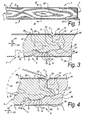
- Figure 1 shows a floor panel 1, which can be obtained by a method according to the invention.
- This relates to a floor panel 1, which at least at two, and in this case at all, opposite sides 2-3, 4-5, has coupling parts 6 allowing that two of such floor panels 1 can be connected to each other at their edges.
- Figure 2 shows from two different series 7-8 each time one floor panel 1, wherein for manufacturing the floor panels 1 of these two series 7-8, a method according to the invention is applied.
- the floor panels 1 in the first series 7 differ from the floor panels 1 in the second series 8 at least in that they have another thickness T.
- the floor panels 1 of the first series 7 are thinner than the floor panels 1 of the second series 8.
- the series 7-8 intended according to the invention comprise more than one floor panel 1 of a certain thickness T, such that a floor covering can be composed of the floor panels 1 of such a series 7-8.
- the coupling parts 6 of these two floor panels 1 comprise a tongue 9 and a groove 10, which is bordered by means of a lower lip 11 and an upper lip 12.
- the lower lip 11 extends over a distance E up to beyond the upper lip 12.
- the coupling parts 6 are provided with locking portions 13, which can effect a locking the in horizontal direction H1.
- these locking portions 13 consist of a recess 14 in the lower lip 11 and a projection 15 at the underside of the tongue 9, wherein this projection 15 can cooperate having said recess 14, when two floor panels 1 of the same series 7-8 cooperate with each other.
- FIGS. 3 and 4 show, in such cooperation at least horizontally active locking surfaces 16-17 are created.
- These locking surfaces provide for that the respective floor panels 1 can not, or only in a limited manner, shift apart from each other in horizontal direction H1.
- the locking surface 17 that is formed on the flanks of the recess 14 is situated at least partially, and in this case entirely, in a portion of the lower lip 11 extending beyond the upper lip 12.
- the method is applied for manufacturing floor panels with coupling parts allowing that two of such floor panels of the same series can be coupled to each other without play in horizontal direction, and still better without play in each direction of the plane perpendicular to the respective sides.
- the method of the present invention comprises at least the step of forming the coupling part 6 having said groove 10, wherein the contour of this coupling part 10, as represented, amongst others, in the floor panels 1 of figure 2 , is composed at least of two portions 18-19, and wherein these two portions 18-19 with floor panels 1 of series 7-8 with different thicknesses T are realized identical.
- the first portion 7 of the contour extends at least from the horizontally active locking surface 17 on the flanks of the recess 14 in the lower lip 11 up to a rising flank portion 20 of this recess 11.
- the second portion 19 extends at least from the underside 21 of the lower lip 12 up to the upper side 22 of the lower lip 11.
- the first portion 18 of the contour in the represented floor panels 1 extends from the point A1 at the distal extremity of the lower lip 11 to the point B1 on said rising flank portion 20 of the recess 14, whereas the second portion 19 extends from the point A2 below the upper edge 23, where the floor panels 1 adjoin each other, up to the point B2 on a flank portion 24 of the lower lip 11, which, globally viewed, has a smaller angle of inclination than the steepest portion of said rising flank portion 20 of the recess 14.
- the respective flank portion 24 of the lower lip 11 is realized flat.
- said first portion 18 of the contour is realized at a relative position in respect to the upper edge 23, which, in respect to its position in the floor panel 1 of said first series 7, is shifted at least laterally, in this case over a distance LG.
- said second portion 19 of the contour of the coupling part 6 having the groove 10 in said second series 8 of floor panels 1, is realized in a relative position, namely at a distance P2 in respect to the upper side 25 of the floor panel, which, in respect to its position in said first series 7 of floor panels 1, namely at a distance P1 in respect to the upper side 25, is shifted at least in a direction transverse to the panel surface.
- the portions 18-19 of the contour extend, each separately, in a continuous and/or uninterrupted manner. However, it is not excluded that, in one or several of said series 7-8, they are locally interrupted, but that the aforementioned two series 18-19 of the contour still extend in a globally identical manner in both series 7-8 of floor panels 1. According to a first example, such local interruption of one or both of said portions 18-19 of the contour may consist at least of an additional cutout formed in the respective portion 18-19 of the contour, whereby a portion of the actual contour portion 18-19 is removed, such as a cutout performed on this contour portion 18-19 by means of a saw or other cutting tool.
- such local interruption may consist at least of an additional contour portion, by means of which two parts of one and the same respective contour portion 18-19 in the one series 8 is mutually shifted in respect to the other series 7.
- this relates to maximum one such interruption per contour portion 18-19, or the respective contour portion 18-19 preferably is divided into maximum two parts only.
- the floor panels 1 of the first series 7 and second series 8 further have the following particular features:
- the lower lip 11 after adjoining the floor panels 1 of both series 7-8, remains in a bent-out position, wherein, due to its elastic resiliency, it forces the floor panels 1 towards each other.
- Such forcing of floor panels 1 towards each other by means of elastic bending of the lower lip 11 is known as such from WO 97/47834 and in the meantime is known to the skilled person as pretension.
- the examples also show the particular form of pretension as it is described in WO 2006/032398 and which results in a reduced risk of the occurrence of creaking noises when walking on a floor covering composed of such floor panels 1.
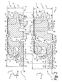
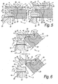
- Figures 5 and 6 represent how the contour of the coupling part 6 having the groove 10 can be formed in both series 7-8 of floor panels 1 by means of a machining treatment by means of at least two milling tools 30-31.
- the milling tools 30-31 applied for the first series 7 are made identical to the milling tools 30-31 applied for the second series 8.
- this relates to one and the same set of milling tools 30-31 comprising at least two milling tools 30-31, namely, on the one hand, a milling tool 30 forming in both series 7-8 of floor panels 1 at least the second portion 19 of the contour of the groove 10, as represented in figure 5 , and, on the other hand, a milling tool 31, which, in both series 7-8 of floor panels 1, forms at least the first series 18 of the contour of the groove 10, as represented in figure 6 .
- said first portion 18 of the contour by means of said milling tool 31 is formed in said second series 8 of floor panels 1 at a position in respect to the upper edge 23, which, in respect to its position in said first series 7 of floor panels 1, is shifted laterally over a distance LG, and that said second portion 19 of the contour in said second series 8 of floor panels 1 is formed at a position in respect to the upper side 25, which, in respect to its position in said first series 7 of floor panels 1, is shifted in transverse direction over a distance HG.
- the floor panels 1 are pressed with their upper side 25 onto a sliding block or other guiding element 32, such that all distances, for example, the distances P1 and P2, are referenced towards this upper side 25.
- a portion of surplus material may be removed and/or the final upper edge 23 may be finished in a fine-treatment step.
- a particular example of such finishing relates to removing a material portion in order to form a chamfer 33, such as the bevels represented in figure 2 .
- chamfer 33 must be seen as optional only and that such floor panels 1 also may be manufactured with straight upper edges 23 adjoining each other. Further, it is noted that such chamfers are known as such, for example, from WO 01/96688 .
- the contour of the coupling part 6 having the tongue 9 may be composed in a similar manner to the contour of the coupling part 6 having the groove 10, independently of the fact whether the groove 10 is composed of two portions 18-19.
- Such method is also applied for manufacturing the floor panels represented in figure 2 and comprises the step of forming the coupling part 6 having the tongue 9 at the opposite side 2 of the floor panel 1, wherein the contour of this coupling part 6 is also composed of at least two portions 34-35.
- this relates to a first portion 34 extending at least from said locking surface 16 of the projection 15 at the underside of the tongue 9 up to a rising flank portion 36 of this projection 15, and to a second portion 35 extending at least from the upper side 37 up to the underside 38 of the tongue 9.
- the first portion 37 of the contour extends from the point A3 at the underside 39 of the floor panel 1 up to the point B3 on said rising flank portion 36 of the protrusion 15, whereas the second portion 35 extends from the point A4 below the upper edge 23, where the floor panels 1 adjoin each other, up to the point B4 on another, preferably more steeply rising, flank portion 40 of the protrusion 15.
- the particularity of the method of the invention consists in that said two portions 34-35 of the coupling part 6 having the tongue 9, in series 7-8 of floor panels 1 of different thickness T, as such are made identical, and that at least said first portion 34 of that contour in said second series 8 of floor panels 1 is realized on a relative position in respect to the upper edge 23, which, in respect to its position in the floor panel 1 from said first series 7, is shifted at least laterally, in this case, over a distance LT.
- the second portion 35 of the contour of the coupling part 6 having the tongue 10 in said second series 8 of floor panels 1 is realized at a relative position, namely, at a distance P2 in respect to the upper side 25 of the floor panel, which, in respect to its position in said first series 7 of floor panels 1, namely, at a distance P1 in respect to the upper side 25, is shifted at least in a direction transverse to the panel surface.
- figures 7 and 8 represent how the contour of the coupling part 6 having the tongue 9 can be formed by means of at least two milling tools 41-42, namely, on the one hand, a milling tool 41 forming in both series 7-8 of floor panels 1 at least the second portion 35 of the contour of the tongue 9, as represented in figure 7 , and, on the other hand, a milling tool 42 forming in both series 7-8 of floor panels 1 at least the first portion 34 of the contour of the tongue 9, as represented in figure 8 .
- Figures 7 and 8 clearly show that in the respective floor panels the first portion 34 of the contour in the first series 7 is realized at a relative position in respect to the upper edge 23, which, in respect to its position in the second series 8 of floor panels 1, is laterally shifted over a distance LT, whereas the second portion is shifted relatively in respect to the upper side 25 of the floor panel in transverse direction over a distance HT.
- the invention also relates to a set of milling tools allowing to manufacture a floor panel according to the method represented in figures 7 and 8 , and that the invention also relates to a floor panel obtained by means of such method.
- the floor panels 1 represented in the figures relate to laminate floor panels with a substrate 43 on the basis of wood-based material, such as MDF or HDF, which is provided with a top layer 44 and a backing layer 45.
- the top layer 44 comprises two carrier sheets 46 soaked in resin or provided with resin
- the backing layer 45 comprises one such carrier sheet 46 provided with resin.
- the method of the invention of course may also be applied for manufacturing other floor panels 1.
- said tongue 9 and groove 10 both when the two floor panels 1 of the first series 7 and when the two floor panels 1 of the second series 8 cooperate with each other, also show vertically active locking surfaces 47-48 at the underside 21 of the upper lip 12 and at the upper side 22 of the lower lip 11, and that said second portion 19 of the contour of the coupling part 6 having the groove 10, both in the floor panels 1 of the first series 7 as in the floor panels 1 of the second series 8, comprises at least these vertically active locking surfaces 47-48.
- contour of the coupling part 6 having the groove 10 and/or the coupling part 6 having the tongue 9 at the second pair of opposite sides 4-5 can be composed in a similar manner of two portions 18-19 and/or 34-35, as described herein above by means of the first pair of opposite sides 2-3.
- Figure 9 shows another particular variant of the present invention, wherein in particular said second portion of the contour 19 in the second series 8 shows a local interruption 49, however, wherein said two portions 18-19 of the contour are extending globally identical in both series 7-8 of floor panels 1.
- Figure 10 clearly shows that the here employed local interruption 49 consists of an additional contour portion 50, by means of which a first part 19A and second part 19B of the second contour portion 19 in the second series 8 of floor panels 1 are mutually shifted compared to their mutual position in the first series 7.
- said first part 19A of the second contour portion 19 extends from the point A2 to an intermediary point I1
- said second part 19B of this contour portion 19 extends from the intermediary point I2 to the point B2.
- the points I1 and I2 of the first and second part 19A-19B adjoin to each other in the first series 7 of floor panels 1, they are, in the second series 8 of floor panels 1, removed from each other in that these points I1 and I2 are connected to each other by the additional contour portion 50.
- the local interruption 49 forms an illustration of the above-mentioned second example of local interruption.
- Such interruption 50 may be useful, when it is desirable, for example, to optimize the thickness of the tongue 9 according to the thickness T of the floor panel 1.
- a thicker tongue 9 and a, preferably substantially corresponding, wider groove 10 is applied.
- such local interruption 50 may be realized by means of milling tools 30, which are composed of at least two cutting portions 30A-30B, the mutual position of which can be varied.
- Such composed milling tools are known as such.
- a first cutting portion 30A of such composed cutting tool 30 is applied for realizing said first part 19A of the second contour portion 19, whereas a second cutting portion 30A is applied for realizing said second portion 19B.
- first part 19A of the second portion 19 of the contour in said second series 8 of floor panels 1 is formed at a position in respect to the upper side 25, which, in respect to its position in said first series 7 of floor panels 1, is shifted in transverse direction over a distance HG1, whereas the position of said second portion 19B in respect to the upper side 25 of the floor panels 1, when the first series 7 is compared to the second series 8, is shifted over a different distance HG2.
- cutting portions 30A-30B form part of different milling tools 30, or in other words are not composed to the same composed milling tool 30.
- the mutual position of the cutting portions 30A-30B must be varied in another manner, for example, by adjusting at least the mutual position of the different milling tools 30 and/or at least by altering the position of a cutting portion 30A-30B in respect to the milling tool 30 upon which it is mounted.
- contour portions 50 preferably extend horizontally, this is as a substantially straight flank between the two parts 19A-19B of the respective locally interrupted portion 19 of the contour. Still better, this straight line is substantially parallel to the axis of rotation of at least one, and preferably of both said cutting parts 30A-30B, which are used for forming the respective parts 19A-19B of the respective contour portion 19.
- first and/or.second contour portions 18-19 are used, which in the first series 7 and/or in the second series 8 show a local interruption 49, however, wherein these first and second portions 18-19 of the contour still extend in a globally identical manner.
- local interruption 49 is meant that this interruption 49, for example, a cutout or an additional contour portion 50, extends only over a limited distance in the respective portion 18-19 of the contour, between the parts 19A-19B of the respective portion 18-19 of the contour, respectively.
- This limited distance preferably is less than 20% of the overall length of the respective contour portion 18-19 or the parts 19A-19B thereof. Still better, it is less than 10, or even less than 5% of the overall length of the respective contour portion 18-19.
Claims (14)
- Verfahren zur Herstellung von Fußbodenpaneelen des Typs, der an mindestens zwei gegenüberliegenden Seiten (2-3) Koppelteile (6) aufweist, welche Koppelteile (6), wenn zwei solche Fußbodenpaneele (1) miteinander zusammenwirken, sowohl eine Verriegelung in vertikaler Richtung (V1), senkrecht zur Ebene der Fußbodenpaneele (1), als auch eine Verriegelung in horizontaler Richtung (H1), senkrecht zu den betreffenden Seiten (2-3) und in der Ebene der Fußbodenpaneele (1), bewerkstelligen, wobei die Verriegelung in vertikaler Richtung (V1) mittels einer Nut- und Feder-Verbindung (9-10) verwirklicht wird, wobei diese Nut (10) durch eine untere Lippe (11) und eine obere Lippe (12) begrenzt ist, und wobei die Koppelteile (6) zur Verwirklichung der Verriegelung in horizontaler Richtung (H1) mit Verriegelungsteilen (13) in Form einer Ausnehmung (14) in der besagten unteren Lippe (11) und eines damit zusammenwirkenden Vorsprungs (15) an der Unterseite der Feder (9) versehen sind, welche, wenn zwei solche Fußbodenpaneele (1) zusammenwirken, mindestens horizontal aktive Verriegelungsflächen (16-17) bilden, wobei die an den Flanken der besagten Ausnehmung (14) gebildete Verriegelungsfläche (17) sich mindestens teilweise in einem Teil der unteren Lippe (11) befindet, der sich über die obere Lippe (12) hinaus erstreckt, wobei das Verfahren mindestens den Schritt des Formens des die Nut (10) aufweisenden Koppelteils (6) umfasst, wobei die Kontur dieses Koppelteils (6) mindestens aus zwei Teilen (18-19) zusammengesetzt ist, nämlich einem ersten Teil (18), der sich mindestens ab der besagten Verriegelungsfläche (17) der Ausnehmung (14) bis zu einem ansteigenden Flankenteil (20) der Ausnehmung (14) erstreckt, und einem zweiten Teil (19), der sich mindestens ab der Unterseite (21) der besagten oberen Lippe (12) bis zu der Oberseite (22) der besagten unteren Lippe (11) erstreckt, dadurch gekennzeichnet, dass das Verfahren zur Herstellung von mindestens zwei Serien (7-8) von Fußbodenpaneelen (1) angewendet wird, wobei die Fußbodenpaneele (1) in einer ersten Serie (7) sich von den Fußbodenpaneelen (1) in einer zweiten Serie (8) mindestens dadurch unterscheiden, dass sie eine unterschiedliche Dicke (T) aufweisen; dass besagte zwei Teile (18-19) der Kontur des die Nut (10) aufweisenden Koppelteils (6) als solches in beiden Serien (7-8) von Fußbodenpaneelen (1) identisch ausgeführt sind; und dass mindestens der besagte erste Teil (18) der Kontur in besagter zweiter Serie (8) von Fußbodenpaneelen (1) in einer relativen Position in Bezug auf die Oberkante (23) des Fußbodenpaneels (1) verwirklicht ist, die in Bezug auf seine Position in der besagten ersten Serie (7) von Fußbodenpaneelen (1) mindestens seitlich verschoben ist.
- Verfahren nach Anspruch 1, dadurch gekennzeichnet, dass besagter zweiter Teil (19) der Kontur des die Nut (10) aufweisenden Koppelteils (6) in besagter zweiter Serie (8) von Fußbodenpaneelen (1) in einer relativen Position in Bezug auf die Oberseite (25) des Fußbodenpaneels (1) verwirklicht ist, die in Bezug auf seine Position in der besagten ersten Serie (7) von Fußbodenpaneelen (1) mindestens in einer Richtung quer zur Paneeloberfläche verschoben ist.
- Verfahren nach Anspruch 1 oder 2, dadurch gekennzeichnet, dass der erste Teil (18) der besagten Kontur und/oder der zweite Teil (19), woraus die Kontur des die Nut (10) aufweisenden Koppelteils (6) zusammengesetzt wird, sich sowohl bei den Fußbodenpaneelen (1) der ersten Serie (7) als auch bei den Fußbodenpaneelen (1) der zweiten Serie (8) jeder an sich ununterbrochen oder kontinuierlich erstrecken.
- Verfahren nach einem der vorgenannten Ansprüche, dadurch gekennzeichnet, dass der besagte zweite Teil (19) sich mindestens bis zu einem Flankenteil (24) an der Oberseite (22) der unteren Lippe (11) erstreckt, wobei sich dieser Flankenteil (24), global gesehen, unter einem kleineren Neigungswinkel erstreckt als der Neigungswinkel des steilsten Teils des vorgenannten ansteigenden Flankenteils (20) der Ausnehmung (14), wobei bevorzugt die Verlängerung (26) des vorgenannten Flankenteils (24) an die Verlängerung des besagten ansteigenden Flankenteils (20) der Ausnehmung (14), die Teil des vorgenannten ersten Teils (18) der Kontur darstellt, anschließt.
- Verfahren nach Anspruch 4, dadurch gekennzeichnet, dass die besagte Kontur in Höhe des Anschlusses (28) sowohl bei den Fußbodenpaneelen (1) der ersten Serie (7) als auch bei den Fußbodenpaneelen (1) der zweiten Serie (8) eine abrupte Änderung des Neigungswinkels zeigt.
- Verfahren nach einem der vorgenannten Ansprüche, dadurch gekennzeichnet, dass die vorgenannte Feder (9) und Nut (10), sowohl wenn zwei Fußbodenpaneele (1) der ersten Serie (7) als auch wenn zwei Fußbodenpaneele (1) der zweiten Serie (8) miteinander zusammenwirken, mindestens vertikal aktive Verriegelungsflächen (47-48) an der Unterseite (21) der oberen Lippe (12) und an der Oberseite (22) der unteren Lippe (11) aufweisen, und dass der besagte zweite Teil (19) der Kontur, sowohl bei den Fußbodenpaneelen (1) der ersten Serie (7) als auch bei den Fußbodenpaneelen (1) der zweiten Serie (8), mindestens diese vertikal aktiven Verriegelungsflächen (47-48) umfasst.
- Verfahren nach einem der vorgenannten Ansprüche, dadurch gekennzeichnet, dass die Fußbodenpaneele (1) der ersten Serie (7) dünner als die Fußbodenpaneele (1) der zweiten Serie (8) sind und dass die vorgenannten zwei Teile (18-19) so zusammengesetzt sind, dass sich die Fußbodenpaneele (1) in einer ersten Serie (7) von den Fußbodenpaneelen (1) in einer zweiten Serie (8) auch dadurch unterscheiden, dass besagte Kontur des die Nut (10) aufweisenden Koppelteils (6) eine oder mehrere der folgenden Eigenschaften aufweist:- dass besagter erster Teil (18) der Kontur auch das distale Ende der besagten unteren Lippe (11) umfasst;- dass besagter zweiter Teil (19) der Kontur mindestens die gesamte Unterseite (21) der oberen Lippe (12) umfasst;- dass besagte untere Lippe (11) bei den Fußbodenpaneelen (1) der ersten Serie (7) so ausgebildet ist, dass sie sich über einen kleineren Abstand (E) über besagte obere Lippe (12) der Nut (10) hinaus erstreckt, als dies bei den Fußbodenpaneelen (1) der zweiten Serie (8) der Fall ist;- dass besagte Ausnehmung (14) bei den Fußbodenpaneelen (1) der ersten Serie (7) in Bezug auf das Fußbodenpaneel (1) proximaler geformt wird, als dies bei den Fußbodenpaneelen (1) der zweiten Serie (8) der Fall ist;- dass besagte Ausnehmung (14) bei den Fußbodenpaneelen (1) der ersten Serie (7) mit einem tiefsten Punkt (29) geformt wird, der in Bezug auf das Fußbodenpaneel (1) proximaler gelegen ist, als dies bei den Fußbodenpaneelen (1) der zweiten Serie (8) der Fall ist;- dass die untere Lippe (11) bei den Fußbodenpaneelen (1) der ersten Serie (7) mit einem dünnsten Querschnitt geformt wird, der dünner ist, als dies bei den Fußbodenpaneelen (1) der zweiten Serie (8) der Fall ist.
- Verfahren nach einem der vorgenannten Ansprüche, dadurch gekennzeichnet, dass es zur Herstellung von Serien (7-8) von Fußbodenpaneelen (1) angewendet wird, die sich mindestens dadurch unterscheiden, dass die Fußbodenpaneele (1) in den verschiedenen Serien (7-8) eine unterschiedliche Dicke (T) aufweisen und diese unterschiedlichen Dicken (T) aus einem Bereich von 9 bis 16 und noch besser von 10 bis 12 Millimeter ausgewählt sind.
- Verfahren nach einem der Ansprüche 1 bis 9, dadurch gekennzeichnet, dass es zur Herstellung von Serien (7-8) von Fußbodenpaneelen (1) angewendet wird, die sich mindestens dadurch unterscheiden, dass die Fußbodenpaneele (1) in den verschiedenen Serien (7-8) eine unterschiedliche Dicke (T) aufweisen und diese unterschiedlichen Dicken (T) aus einem Bereich von 6 bis 10 und noch besser von 7 bis 9,5 Millimeter ausgewählt sind.
- Verfahren nach einem der vorgenannten Ansprüche, wobei, statt mit identischen ersten Teilen (18) und zweiten Teilen (19) der Kontur zu arbeiten, erste und/oder zweite Konturteile (18-19) verwendet werden, die, in der ersten Serie (7) und/oder in der zweiten Serie (8) von Fußbodenpaneelen (1), eine örtliche Unterbrechung (49) aufweisen, wobei sich jedoch diese ersten und zweiten Konturteile (18-19) noch stets auf eine global identische Weise erstrecken.
- Verfahren nach einem der vorgenannten Ansprüche, dadurch gekennzeichnet, dass die Kontur des die Nut (10) aufweisenden Koppelteils (6) in beiden Serien (7-8) von Fußbodenpaneelen (1) mittels einer spanenden Bearbeitung mittels mindestens zweier Fräswerkzeuge (30-31) geformt wird und dass die besagten zwei Werkzeuge (30-31) bestehen aus, einerseits, einem ersten Fräswerkzeug (31), das mindestens den besagten ersten Teil (18) der vorgenannten Kontur formt, und andererseits einem zweiten Fräswerkzeug (30), das mindestens den besagten zweiten Teil (19) der vorgenannten Kontur formt.
- Verfahren nach Anspruch 11, dadurch gekennzeichnet, dass die besagten, für die erste Serie (7) von Fußbodenpaneelen (1) angewendeten zwei Werkzeuge (30-31) identisch zu den besagten, für die zweite Serie (8) von Fußbodenpaneelen (1) angewendeten zwei Werkzeugen (30, 31) ausgeführt sind.
- Verfahren nach Anspruch 12, dadurch gekennzeichnet, dass für die vorgenannten zwei Fräswerkzeuge (30-31) in der ersten Serie (7) und der zweiten Serie (8) von Fußbodenpaneelen (1) die gleichen Fräswerkzeuge (30-31) angewendet werden.
- Verfahren nach einem der Ansprüche 11 bis 13, dadurch gekennzeichnet, dass mindestens eines der besagten zwei Werkzeuge (30-31) aus einem zusammengesetzten Fräswerkzeug mit mindestens zwei Schneidteilen (30A-30B) besteht, deren Position zueinander variiert werden kann.
Applications Claiming Priority (2)
| Application Number | Priority Date | Filing Date | Title |
|---|---|---|---|
| BE2006/0399A BE1017232A6 (nl) | 2006-07-19 | 2006-07-19 | Werkwijze voor het vervaardigen van vloerpanelen, vloerpanelen volgens deze werkwijze verkregen en set van gereedschappen hierbij aangewend. |
| PCT/IB2007/002001 WO2008010060A1 (en) | 2006-07-19 | 2007-07-09 | Method for manufacturing floor panels, floor panels obtained by this method and set of tools applied therewith. |
Publications (2)
| Publication Number | Publication Date |
|---|---|
| EP2064035A1 EP2064035A1 (de) | 2009-06-03 |
| EP2064035B1 true EP2064035B1 (de) | 2011-05-25 |
Family
ID=38564430
Family Applications (1)
| Application Number | Title | Priority Date | Filing Date |
|---|---|---|---|
| EP07735005A Not-in-force EP2064035B1 (de) | 2006-07-19 | 2007-07-09 | Verfahren zur herstellung von fussbodenpaneelen |
Country Status (6)
| Country | Link |
|---|---|
| US (1) | US20090249731A1 (de) |
| EP (1) | EP2064035B1 (de) |
| CN (1) | CN101489744B (de) |
| AT (1) | ATE510667T1 (de) |
| BE (1) | BE1017232A6 (de) |
| WO (1) | WO2008010060A1 (de) |
Families Citing this family (15)
| Publication number | Priority date | Publication date | Assignee | Title |
|---|---|---|---|---|
| CN101492950B (zh) * | 2008-09-10 | 2011-01-12 | 滁州扬子木业有限公司 | 带有锁合装置的地板 |
| KR100958396B1 (ko) * | 2009-03-31 | 2010-05-18 | 오광석 | 바닥재 |
| CA3209449A1 (en) * | 2010-01-11 | 2011-07-14 | Valinge Innovation Ab | Floor covering with interlocking design |
| BE1019331A5 (nl) | 2010-05-10 | 2012-06-05 | Flooring Ind Ltd Sarl | Vloerpaneel en werkwijzen voor het vervaardigen van vloerpanelen. |
| BE1019891A5 (nl) * | 2011-03-28 | 2013-02-05 | Unilin Bvba | Samengesteld element en rugwandconstructie hierbij toegepast. |
| US20140083034A1 (en) * | 2012-09-19 | 2014-03-27 | Dubon Associates, Inc. | Stable flooring products and method of making same |
| EP3358101B1 (de) * | 2013-03-25 | 2019-11-06 | Välinge Innovation AB | Bodenplatten mit einem mechanischen verriegelungssystem und verfahren zur herstellung solch eines verriegelungssystems |
| WO2016207251A1 (en) * | 2015-06-26 | 2016-12-29 | Tarkett Gdl S.A. | Floorboards with horizontally and vertically locking connecting profiles |
| EA201992222A1 (ru) * | 2017-09-28 | 2020-02-10 | Юнилин, Бвба | Плита и способ изготовления плиты |
| EP3908436B1 (de) * | 2019-01-08 | 2024-04-10 | Unilin, BV | Verfahren, vorrichtung, nutzung und rotierendes werkzeug für kantenprofielierung von panelen |
| BE1027883B1 (nl) * | 2019-12-18 | 2021-07-27 | Unilin Bv | Werkwijze voor het vervaardigen van panelen |
| NL2025115B1 (en) * | 2020-03-12 | 2021-10-19 | Northann Building Solutions LLC | Decorative surface covering element, surface covering element covering, and method of producing such a decorative surface covering element |
| BE1028427B1 (nl) | 2020-06-24 | 2022-02-01 | Flooring Ind Ltd Sarl | Vloerpanelen en werkwijze voor het vervaardigen van vloerpanelen en snijgereedschappen hierbij aangewend |
| CN111702231A (zh) * | 2020-07-09 | 2020-09-25 | 博深普锐高(上海)工具有限公司 | 一种石塑地板锁扣的加工工艺 |
| BE1030681B1 (nl) | 2022-07-01 | 2024-01-29 | Flooring Ind Ltd Sarl | Set van freeswerktuigen en werkwijze voor het vervaardigen van panelen |
Family Cites Families (6)
| Publication number | Priority date | Publication date | Assignee | Title |
|---|---|---|---|---|
| BE1010487A6 (nl) * | 1996-06-11 | 1998-10-06 | Unilin Beheer Bv | Vloerbekleding bestaande uit harde vloerpanelen en werkwijze voor het vervaardigen van dergelijke vloerpanelen. |
| SE517183C2 (sv) * | 2000-01-24 | 2002-04-23 | Valinge Aluminium Ab | Låssystem för mekanisk hopfogning av golvskivor, golvskiva försedd med låssystemet och metod för framställning av sådana golvskivor |
| PT1676720E (pt) * | 2000-06-13 | 2011-02-28 | Flooring Ind Ltd | Revestimento de pavimentos |
| BE1013569A3 (nl) * | 2000-06-20 | 2002-04-02 | Unilin Beheer Bv | Vloerbekleding. |
| US6851241B2 (en) * | 2001-01-12 | 2005-02-08 | Valinge Aluminium Ab | Floorboards and methods for production and installation thereof |
| BE1016216A5 (nl) * | 2004-09-24 | 2006-05-02 | Flooring Ind Ltd | Vloerpaneel en vloerbekleding samengesteld uit dergeljke vloerpanelen. |
-
2006
- 2006-07-19 BE BE2006/0399A patent/BE1017232A6/nl not_active IP Right Cessation
-
2007
- 2007-07-09 US US12/374,090 patent/US20090249731A1/en not_active Abandoned
- 2007-07-09 CN CN2007800259349A patent/CN101489744B/zh not_active Expired - Fee Related
- 2007-07-09 AT AT07735005T patent/ATE510667T1/de not_active IP Right Cessation
- 2007-07-09 WO PCT/IB2007/002001 patent/WO2008010060A1/en active Application Filing
- 2007-07-09 EP EP07735005A patent/EP2064035B1/de not_active Not-in-force
Also Published As
| Publication number | Publication date |
|---|---|
| ATE510667T1 (de) | 2011-06-15 |
| CN101489744B (zh) | 2012-05-30 |
| CN101489744A (zh) | 2009-07-22 |
| US20090249731A1 (en) | 2009-10-08 |
| WO2008010060A1 (en) | 2008-01-24 |
| EP2064035A1 (de) | 2009-06-03 |
| BE1017232A6 (nl) | 2008-05-06 |
Similar Documents
| Publication | Publication Date | Title |
|---|---|---|
| EP2064035B1 (de) | Verfahren zur herstellung von fussbodenpaneelen | |
| US10975578B2 (en) | Floor covering, floor element and method for manufacturing floor elements | |
| RU2418925C1 (ru) | Покрытие для пола | |
| US8261508B2 (en) | Floor panel and floor covering consisting of such floor panels | |
| US7051486B2 (en) | Mechanical locking system for floating floor | |
| EP1640530B1 (de) | Fussbodenpaneel und aus solchen Paneelen zusammengesetzter Fussbodenbelag | |
| US7637068B2 (en) | Mechanical locking system for floorboards | |
| US20230228100A1 (en) | Floor panels and method for producing floor panels and cutting tools used therein |
Legal Events
| Date | Code | Title | Description |
|---|---|---|---|
| PUAI | Public reference made under article 153(3) epc to a published international application that has entered the european phase |
Free format text: ORIGINAL CODE: 0009012 |
|
| 17P | Request for examination filed |
Effective date: 20090211 |
|
| AK | Designated contracting states |
Kind code of ref document: A1 Designated state(s): AT BE BG CH CY CZ DE DK EE ES FI FR GB GR HU IE IS IT LI LT LU LV MC MT NL PL PT RO SE SI SK TR |
|
| AX | Request for extension of the european patent |
Extension state: AL BA HR MK RS |
|
| 17Q | First examination report despatched |
Effective date: 20090713 |
|
| RAP1 | Party data changed (applicant data changed or rights of an application transferred) |
Owner name: FLOORING INDUSTRIES LIMITED, SARL |
|
| RTI1 | Title (correction) |
Free format text: METHOD FOR MANUFACTURING FLOOR PANELS |
|
| GRAP | Despatch of communication of intention to grant a patent |
Free format text: ORIGINAL CODE: EPIDOSNIGR1 |
|
| DAX | Request for extension of the european patent (deleted) | ||
| GRAS | Grant fee paid |
Free format text: ORIGINAL CODE: EPIDOSNIGR3 |
|
| GRAA | (expected) grant |
Free format text: ORIGINAL CODE: 0009210 |
|
| AK | Designated contracting states |
Kind code of ref document: B1 Designated state(s): AT BE BG CH CY CZ DE DK EE ES FI FR GB GR HU IE IS IT LI LT LU LV MC MT NL PL PT RO SE SI SK TR |
|
| REG | Reference to a national code |
Ref country code: GB Ref legal event code: FG4D |
|
| REG | Reference to a national code |
Ref country code: CH Ref legal event code: EP |
|
| REG | Reference to a national code |
Ref country code: IE Ref legal event code: FG4D |
|
| REG | Reference to a national code |
Ref country code: DE Ref legal event code: R096 Ref document number: 602007014873 Country of ref document: DE Effective date: 20110707 |
|
| PGFP | Annual fee paid to national office [announced via postgrant information from national office to epo] |
Ref country code: IE Payment date: 20110620 Year of fee payment: 5 Ref country code: LU Payment date: 20110621 Year of fee payment: 5 Ref country code: FR Payment date: 20110701 Year of fee payment: 5 |
|
| PGFP | Annual fee paid to national office [announced via postgrant information from national office to epo] |
Ref country code: NL Payment date: 20110622 Year of fee payment: 5 |
|
| REG | Reference to a national code |
Ref country code: NL Ref legal event code: VDEP Effective date: 20110525 |
|
| PGFP | Annual fee paid to national office [announced via postgrant information from national office to epo] |
Ref country code: BE Payment date: 20110617 Year of fee payment: 5 |
|
| PG25 | Lapsed in a contracting state [announced via postgrant information from national office to epo] |
Ref country code: PT Free format text: LAPSE BECAUSE OF FAILURE TO SUBMIT A TRANSLATION OF THE DESCRIPTION OR TO PAY THE FEE WITHIN THE PRESCRIBED TIME-LIMIT Effective date: 20110926 Ref country code: SE Free format text: LAPSE BECAUSE OF FAILURE TO SUBMIT A TRANSLATION OF THE DESCRIPTION OR TO PAY THE FEE WITHIN THE PRESCRIBED TIME-LIMIT Effective date: 20110525 Ref country code: LT Free format text: LAPSE BECAUSE OF FAILURE TO SUBMIT A TRANSLATION OF THE DESCRIPTION OR TO PAY THE FEE WITHIN THE PRESCRIBED TIME-LIMIT Effective date: 20110525 |
|
| PGFP | Annual fee paid to national office [announced via postgrant information from national office to epo] |
Ref country code: CH Payment date: 20110719 Year of fee payment: 5 |
|
| PG25 | Lapsed in a contracting state [announced via postgrant information from national office to epo] |
Ref country code: AT Free format text: LAPSE BECAUSE OF FAILURE TO SUBMIT A TRANSLATION OF THE DESCRIPTION OR TO PAY THE FEE WITHIN THE PRESCRIBED TIME-LIMIT Effective date: 20110525 Ref country code: GR Free format text: LAPSE BECAUSE OF FAILURE TO SUBMIT A TRANSLATION OF THE DESCRIPTION OR TO PAY THE FEE WITHIN THE PRESCRIBED TIME-LIMIT Effective date: 20110826 Ref country code: FI Free format text: LAPSE BECAUSE OF FAILURE TO SUBMIT A TRANSLATION OF THE DESCRIPTION OR TO PAY THE FEE WITHIN THE PRESCRIBED TIME-LIMIT Effective date: 20110525 Ref country code: SI Free format text: LAPSE BECAUSE OF FAILURE TO SUBMIT A TRANSLATION OF THE DESCRIPTION OR TO PAY THE FEE WITHIN THE PRESCRIBED TIME-LIMIT Effective date: 20110525 Ref country code: CY Free format text: LAPSE BECAUSE OF FAILURE TO SUBMIT A TRANSLATION OF THE DESCRIPTION OR TO PAY THE FEE WITHIN THE PRESCRIBED TIME-LIMIT Effective date: 20110525 Ref country code: LV Free format text: LAPSE BECAUSE OF FAILURE TO SUBMIT A TRANSLATION OF THE DESCRIPTION OR TO PAY THE FEE WITHIN THE PRESCRIBED TIME-LIMIT Effective date: 20110525 Ref country code: ES Free format text: LAPSE BECAUSE OF FAILURE TO SUBMIT A TRANSLATION OF THE DESCRIPTION OR TO PAY THE FEE WITHIN THE PRESCRIBED TIME-LIMIT Effective date: 20110905 Ref country code: IS Free format text: LAPSE BECAUSE OF FAILURE TO SUBMIT A TRANSLATION OF THE DESCRIPTION OR TO PAY THE FEE WITHIN THE PRESCRIBED TIME-LIMIT Effective date: 20110925 |
|
| PG25 | Lapsed in a contracting state [announced via postgrant information from national office to epo] |
Ref country code: NL Free format text: LAPSE BECAUSE OF FAILURE TO SUBMIT A TRANSLATION OF THE DESCRIPTION OR TO PAY THE FEE WITHIN THE PRESCRIBED TIME-LIMIT Effective date: 20110525 Ref country code: MT Free format text: LAPSE BECAUSE OF FAILURE TO SUBMIT A TRANSLATION OF THE DESCRIPTION OR TO PAY THE FEE WITHIN THE PRESCRIBED TIME-LIMIT Effective date: 20110525 |
|
| PG25 | Lapsed in a contracting state [announced via postgrant information from national office to epo] |
Ref country code: EE Free format text: LAPSE BECAUSE OF FAILURE TO SUBMIT A TRANSLATION OF THE DESCRIPTION OR TO PAY THE FEE WITHIN THE PRESCRIBED TIME-LIMIT Effective date: 20110525 Ref country code: CZ Free format text: LAPSE BECAUSE OF FAILURE TO SUBMIT A TRANSLATION OF THE DESCRIPTION OR TO PAY THE FEE WITHIN THE PRESCRIBED TIME-LIMIT Effective date: 20110525 |
|
| PG25 | Lapsed in a contracting state [announced via postgrant information from national office to epo] |
Ref country code: SK Free format text: LAPSE BECAUSE OF FAILURE TO SUBMIT A TRANSLATION OF THE DESCRIPTION OR TO PAY THE FEE WITHIN THE PRESCRIBED TIME-LIMIT Effective date: 20110525 Ref country code: MC Free format text: LAPSE BECAUSE OF NON-PAYMENT OF DUE FEES Effective date: 20110731 Ref country code: PL Free format text: LAPSE BECAUSE OF FAILURE TO SUBMIT A TRANSLATION OF THE DESCRIPTION OR TO PAY THE FEE WITHIN THE PRESCRIBED TIME-LIMIT Effective date: 20110525 Ref country code: DK Free format text: LAPSE BECAUSE OF FAILURE TO SUBMIT A TRANSLATION OF THE DESCRIPTION OR TO PAY THE FEE WITHIN THE PRESCRIBED TIME-LIMIT Effective date: 20110525 Ref country code: RO Free format text: LAPSE BECAUSE OF FAILURE TO SUBMIT A TRANSLATION OF THE DESCRIPTION OR TO PAY THE FEE WITHIN THE PRESCRIBED TIME-LIMIT Effective date: 20110525 |
|
| PLBE | No opposition filed within time limit |
Free format text: ORIGINAL CODE: 0009261 |
|
| STAA | Information on the status of an ep patent application or granted ep patent |
Free format text: STATUS: NO OPPOSITION FILED WITHIN TIME LIMIT |
|
| REG | Reference to a national code |
Ref country code: FR Ref legal event code: ST Effective date: 20120330 |
|
| GBPC | Gb: european patent ceased through non-payment of renewal fee |
Effective date: 20110825 |
|
| PG25 | Lapsed in a contracting state [announced via postgrant information from national office to epo] |
Ref country code: FR Free format text: LAPSE BECAUSE OF NON-PAYMENT OF DUE FEES Effective date: 20110801 |
|
| 26N | No opposition filed |
Effective date: 20120228 |
|
| PG25 | Lapsed in a contracting state [announced via postgrant information from national office to epo] |
Ref country code: IT Free format text: LAPSE BECAUSE OF FAILURE TO SUBMIT A TRANSLATION OF THE DESCRIPTION OR TO PAY THE FEE WITHIN THE PRESCRIBED TIME-LIMIT Effective date: 20110525 |
|
| REG | Reference to a national code |
Ref country code: DE Ref legal event code: R097 Ref document number: 602007014873 Country of ref document: DE Effective date: 20120228 |
|
| PG25 | Lapsed in a contracting state [announced via postgrant information from national office to epo] |
Ref country code: GB Free format text: LAPSE BECAUSE OF NON-PAYMENT OF DUE FEES Effective date: 20110825 |
|
| PGFP | Annual fee paid to national office [announced via postgrant information from national office to epo] |
Ref country code: DE Payment date: 20120620 Year of fee payment: 6 |
|
| REG | Reference to a national code |
Ref country code: CH Ref legal event code: PL |
|
| PG25 | Lapsed in a contracting state [announced via postgrant information from national office to epo] |
Ref country code: LI Free format text: LAPSE BECAUSE OF NON-PAYMENT OF DUE FEES Effective date: 20120731 Ref country code: CH Free format text: LAPSE BECAUSE OF NON-PAYMENT OF DUE FEES Effective date: 20120731 |
|
| REG | Reference to a national code |
Ref country code: IE Ref legal event code: MM4A |
|
| PG25 | Lapsed in a contracting state [announced via postgrant information from national office to epo] |
Ref country code: BG Free format text: LAPSE BECAUSE OF FAILURE TO SUBMIT A TRANSLATION OF THE DESCRIPTION OR TO PAY THE FEE WITHIN THE PRESCRIBED TIME-LIMIT Effective date: 20110825 |
|
| PG25 | Lapsed in a contracting state [announced via postgrant information from national office to epo] |
Ref country code: IE Free format text: LAPSE BECAUSE OF NON-PAYMENT OF DUE FEES Effective date: 20120709 |
|
| PG25 | Lapsed in a contracting state [announced via postgrant information from national office to epo] |
Ref country code: TR Free format text: LAPSE BECAUSE OF FAILURE TO SUBMIT A TRANSLATION OF THE DESCRIPTION OR TO PAY THE FEE WITHIN THE PRESCRIBED TIME-LIMIT Effective date: 20110525 |
|
| PG25 | Lapsed in a contracting state [announced via postgrant information from national office to epo] |
Ref country code: HU Free format text: LAPSE BECAUSE OF FAILURE TO SUBMIT A TRANSLATION OF THE DESCRIPTION OR TO PAY THE FEE WITHIN THE PRESCRIBED TIME-LIMIT Effective date: 20110525 |
|
| REG | Reference to a national code |
Ref country code: DE Ref legal event code: R119 Ref document number: 602007014873 Country of ref document: DE Effective date: 20140201 |
|
| PG25 | Lapsed in a contracting state [announced via postgrant information from national office to epo] |
Ref country code: DE Free format text: LAPSE BECAUSE OF NON-PAYMENT OF DUE FEES Effective date: 20140201 |
|
| PG25 | Lapsed in a contracting state [announced via postgrant information from national office to epo] |
Ref country code: LU Free format text: LAPSE BECAUSE OF NON-PAYMENT OF DUE FEES Effective date: 20120709 |
|
| PG25 | Lapsed in a contracting state [announced via postgrant information from national office to epo] |
Ref country code: BE Free format text: THE PATENT HAS BEEN ANNULLED BY A DECISION OF A NATIONAL AUTHORITY Effective date: 20110525 |