EP2062549A1 - Disk-Implantat - Google Patents
Disk-Implantat Download PDFInfo
- Publication number
- EP2062549A1 EP2062549A1 EP07076010A EP07076010A EP2062549A1 EP 2062549 A1 EP2062549 A1 EP 2062549A1 EP 07076010 A EP07076010 A EP 07076010A EP 07076010 A EP07076010 A EP 07076010A EP 2062549 A1 EP2062549 A1 EP 2062549A1
- Authority
- EP
- European Patent Office
- Prior art keywords
- implant
- shaft
- foot
- disk
- implant according
- Prior art date
- Legal status (The legal status is an assumption and is not a legal conclusion. Google has not performed a legal analysis and makes no representation as to the accuracy of the status listed.)
- Withdrawn
Links
- 239000007943 implant Substances 0.000 title claims abstract description 129
- 238000003780 insertion Methods 0.000 claims description 20
- 230000037431 insertion Effects 0.000 claims description 20
- 239000004568 cement Substances 0.000 abstract description 2
- 238000004804 winding Methods 0.000 abstract 1
- 210000000988 bone and bone Anatomy 0.000 description 6
- 230000001054 cortical effect Effects 0.000 description 5
- 238000010883 osseointegration Methods 0.000 description 3
- 230000001055 chewing effect Effects 0.000 description 2
- 238000003801 milling Methods 0.000 description 2
- 241001295925 Gegenes Species 0.000 description 1
- 241001465754 Metazoa Species 0.000 description 1
- 210000003484 anatomy Anatomy 0.000 description 1
- 230000015572 biosynthetic process Effects 0.000 description 1
- 230000001419 dependent effect Effects 0.000 description 1
- 238000011161 development Methods 0.000 description 1
- 230000018109 developmental process Effects 0.000 description 1
- 230000000694 effects Effects 0.000 description 1
- 238000002513 implantation Methods 0.000 description 1
- 239000000126 substance Substances 0.000 description 1
Images
Classifications
-
- A—HUMAN NECESSITIES
- A61—MEDICAL OR VETERINARY SCIENCE; HYGIENE
- A61C—DENTISTRY; APPARATUS OR METHODS FOR ORAL OR DENTAL HYGIENE
- A61C8/00—Means to be fixed to the jaw-bone for consolidating natural teeth or for fixing dental prostheses thereon; Dental implants; Implanting tools
- A61C8/001—Multiple implanting technique, i.e. multiple component implants introduced in the jaw from different directions
Definitions
- the invention relates to a disk implant, which is anchored by basal osseointegration in the jawbone and serves to receive and attach a denture or a crown.
- EP 0 935 949 B1 are implants with an implant foot consisting of two adjacent rings - EP 1 050 282 B1 - implants and implants, the foot part of which is composed of different joined geometrical shapes with different surface areas - DE 202 02 424.5 .
- the need for disk implants with different configuration of the implant foot necessarily results from the respective individual requirements and conditions for the insertion of the implant and for ensuring a permanently secure fit of the inserted implant.
- These conditions and conditions include, for example, the individual anatomy of the jawbone, the existing bone substance and the implantation area in the jaw of a patient. These and other requirements and conditions can not be met by disk implants with a consistently uniform implant foot.
- the invention has for its object to provide a Implantatfuß for a disk implant, with the largest possible support of Implantatfußes on the cortex of the jawbone can be achieved even with smaller outer foot dimensions after insertion of the implant.
- the implant foot of the implant according to the invention possess over a circular angle ⁇ of 260 ° to 280 ° a circular contour, followed by two longitudinal sides connect, which are arranged symmetrically to the central axis of the implant foot and an angle ⁇ of 35 ° to 55 °.
- the longitudinal axes terminate outside the full circle of the circular contour and are connected to each other via a terminating radius, wherein in the end region of the longitudinal sides a through hole is provided which serves for example for receiving a locking screw which fixes the inserted implant against rotation.
- the shaft of the implant which is provided on the head side, for example, with an abutment or a head thread or is designed as a cement animal post, preferably has an oval or elliptical profile, wherein the longitudinal axis of this profile is in the direction of insertion of the implant.
- a T-shaped implant bed in the jawbone is produced in a surgical manner and then the implant from the outside of the jaw bone, basal inserted into the implant bed. After reaching the intended final insertion position, the implant is optionally rotated in the implant bed about its longitudinal axis to the left or right, that one of the long sides, which adjoin the round contour of the implant foot, completely rests on the cortical bone of the jaw bone.
- the left or right rotation of the implant in the implant bed also changes the position of the longitudinal axis of the profile of the implant shaft relative to the direction of insertion or relative to the longitudinal axis of the vertical part of the implant bed. Since it is hardly possible despite great care to make the vertical part of the implant bed precisely to the respective profile cross section of the implant shaft, come in an oval to elliptical profile, the long sides of this profile by the left or right rotation of the implant in direct contact with the walls of the vertical part of the implant bed and are clamped with these.
- At least one anti-rotation for example in the form of a flat or flat side is arranged, which cooperates with a corresponding counterpart in the receiving bore of a body part and prevents self-rotation of the arranged on the abutment on the abutment crown or other dentures safely ,
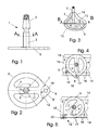
- the disk implant 1 has, as out Fig. 1 shows a well-known structural design and consists of the Implantatfuß 5 and the orthogonal to Implantatfuß 5 arranged implant shaft 2, which is fixedly connected via the web 4 with the Implantatfuß 5 and the head side with an abutment 3 for receiving and fixing a crown or the body part a denture completes.
- the foot section 6 of the implant foot 5 has a circular contour which approximately corresponds to the diameter of the milling tool for producing the implant bed 16 and extends over a circular angle ⁇ of 260 ° to 280 °.
- This circular contour is followed by two longitudinal sides 7 and 8 which are arranged symmetrically to the central axis 11 of the implant foot 5 and whose ends, which extend beyond the full circle 12 of the circular contour, are interconnected by a radius 9 terminating the configuration of the implant foot 5 are.
- a through hole 10 is provided, which serves for receiving a locking screw in the event that the inserted disc implant is not rotated after reaching its final insertion position in the implant bed.
- the locking screw is screwed into the jawbone in order to additionally fix the inserted implant and secure it against possible rotation - Fig. 4 ,
- FIGS Fig. 3 to 5 The insertion of the disc implant 1 according to the invention, which is anchored in the jawbone 13 by basal osseointegration and inserted in the direction of insertion 18 from the outside of the jawbone 13 in an implant bed 16 previously made by milling in a surgical manner, is shown in FIGS Fig. 3 to 5 shown schematically.
- Fig. 4 is the inserted disk implant 1 in its final insertion position and is clamped in the implant bed 16 that, due to the inventive design, large surface portions of the implant foot 5 rest on the cortical bone 14 of the jaw bone 13.
- the disk implant 1 may, to a limited extent, deflect into the cancellous bone 15 of the jawbone 13 in the event of a possible peak load, analogously to a natural tooth.
- the basis for this is the elasticity created in the region of the implant foot 5 by the structural design of the implant base 5 and by the connection of the implant base 5 and the implant shaft 2 Fig. 4 Inserted disk implant 1 is not rotated in the implant bed 16, it can be fixed by inserting a locking screw in the through hole 10 in addition to its restraint in the implant bed, as already described above.
- the implant according to the invention after reaching its final insertion position in Implant bed 16 optionally rotated by approx. 45 ° to the right or left. After completion of the left or right turn, as in Fig. 5 shown, one of the longitudinal sides 7; 8 of the implant foot 5 completely on the cortical bone 14 of the jaw bone 13 and thus increases the bearing surface. In this end position, the inserted disc implant 1, which is already clamped in the horizontal part of the implant bed 16, additionally fixed by a locking screw 20.
- the implant shaft 2 preferably has an oval to elliptical profile, Fig. 2 to 5 .
- This measure has the advantage on the one hand that the light width of the vertical part 17 of the implant bed 16 is milled smaller for the introduction of the disk implant 1 can be and the implant shaft 2 compared to a conventional round implant shaft yet has a larger profile cross-section and is thus able to absorb higher forces and enter about the Implantatfuß 5 in the jawbone 13.
Landscapes
- Health & Medical Sciences (AREA)
- Oral & Maxillofacial Surgery (AREA)
- Orthopedic Medicine & Surgery (AREA)
- Dentistry (AREA)
- Epidemiology (AREA)
- Life Sciences & Earth Sciences (AREA)
- Animal Behavior & Ethology (AREA)
- General Health & Medical Sciences (AREA)
- Public Health (AREA)
- Veterinary Medicine (AREA)
- Dental Prosthetics (AREA)
Abstract
Description
- Die Erfindung betrifft ein Disk-Implantat, das durch basale Osseointegration im Kieferknochen verankert wird und zur Aufnahme und Befestigung eines Zahnersatzes oder einer Krone dient.
- Für die Ausbildung und Anordnung des Implantatfußes von Disk-Implantaten, über den das Implantat im Kieferknochen durch basale Osseointegration verankert ist und die vom Implantat aufgenommenen Kaukräfte in den Kieferknochen eingetragen werden, sind bereits die unterschiedlichsten Lösungen vorgeschlagen worden.
- Neben Implantaten mit einem annähernd quadratischen bis rechteckigen Implantatfuß -
DE 299 17 858.7 ,DE 3 018 255 - oder Implantaten, deren Fußteil durch eine oder mehrere übereinander liegende runde Scheiben mit gleichem oder unterschiedlichem Scheibendurchmesser gebildet wird -DE 199 48 910 A1 ,EP 0 935 949 B1 , sind Implantate mit einem Implantatfuß, der aus zwei nebeneinander liegenden Ringen -EP 1 050 282 B1 - besteht und Implantate, deren Fußteil sich aus unterschiedlichen, aneinandergefügten geometrischen Formen mit unterschiedlichen Flächeninhalten zusammensetzt -DE 202 02 424.5 ,EP 1 050 282 B1 undEP 1 336 388 B1 - bekannt. - Die Notwendigkeit nach Disk-Implantaten mit unterschiedlicher Konfiguration des Implantatfußes ergibt sich zwangsweise aus den jeweiligen individuellen Voraussetzungen und Bedingungen für die Insertion des Implantates und für die Gewährleistung eines dauerhaft festen Sitzes des inserierten Implantates. Zu diesen Voraussetzungen und Bedingungen gehören beispielsweise die individuelle Anatomie des Kieferknochens, die vorhandene Knochensubstanz und das Implantationsgebiet im Kiefer eines Patienten. Diese und weitere Voraussetzungen und Bedingungen können durch Disk-Implantate mit einem durchgängig einheitlichen ausgebildeten Implantatfuß nicht erfüllt werden.
- Der Erfindung liegt die Aufgabe zugrunde, einen Implantatfuß für ein Disk-Implantat anzugeben, mit dem auch bei kleineren äußeren Fußabmessungen nach der Insertion des Implantates eine größtmögliche Auflage des Implantatfußes auf der Kortikalis des Kieferknochen erreicht werden kann.
- Erfindungsgemäß wird die Aufgabe durch ein Disk-Implantat nach den Merkmalen von Anspruch 1 gelöst. Vorteilhafte Weiterbildungen des Erfindungsgegenstandes ergeben sich aus den Unteransprüchen 2 bis 9.
- Der Implantatfuß des erfindungsgemäßen Implantates besitz über einen Kreiswinkel α von 260° bis 280° eine kreisrunde Kontur, an die sich zwei Längsseiten anschließen, die symmetrisch zur Mittelachse des Implantatfußes angeordnet sind und einen Winkel β von 35° bis 55° einschließen. Die Längsachsen enden außerhalb des Vollkreises der kreisrunden Kontur und sind über einen abschließenden Radius miteinander verbunden, wobei im Endbereich der Längsseiten eine Durchgangsbohrung vorgesehen ist, die beispielsweise zur Aufnahme einer Sicherungsschraube dient, die das inserierte Implantat gegen Rotation fixiert.
- Der Schaft des Implantates, der kopfseitig beispielsweise mit einem Abutment oder mit einem Kopfgewinde versehen oder als Zementtierpfosten ausgebildet ist, besitzt vorzugsweise ein ovales bzw. elliptisches Profil, wobei die Längsachse dieses Profils in der Insertionsrichtung des Implantates liegt.
- Für die Insertion des erfindungsgemäßen Implantates wird auf chirurgische Weise ein T-förmig ausgebildetes Implantatbett im Kieferknochen hergestellt und anschließend das Implantat von der Außenseite des Kieferknochens her, basal in das Implantatbett eingesetzt. Nach Erreichen der vorgesehenen finalen Einschubposition wird das Implantat im Implantatbett wahlweise so um seine Längsachse nach links oder rechts gedreht, dass eine der Längsseiten, die sich an die runde Kontur des Implantatfußes anschließen, vollständig auf der Kortikales des Kieferknochens aufliegt.
- Mit der Links- oder Rechtsdrehung des Implantates im Implantatbett verändert sich auch die Lage der Längsachse des Profils des Implantatschaftes gegenüber der Insertionsrichtung bzw. gegenüber der Längsachse des vertikalen Teiles des Implantatbettes. Da es trotz größter Sorgfalt kaum möglich ist, den vertikalen Teil des Implantatbettes passgenau zum jeweiligen Profilquerschnitt des Implantatschaftes herzustellen, kommen bei einem ovalen bis elliptischen Profil die Längsseiten dieses Profils durch die Links- oder Rechtsdrehung des Implantats in unmittelbaren Kontakt mit den Wandungen des vertikalen Teiles des Implantatbettes und werden mit diesen verspannt.
- In der Mantelfläche des Abutmens ist ferner mindestens eine Rotationssicherung, beispielsweise in Form einer Abflachung oder einer Flachseite angeordnet, die mit einem entsprechenden Gegenstück in der Aufnahmebohrung eines Aufbauteiles zusammenwirkt und eine Eigenrotation der auf dem Abutment über das Aufbauteil angeordneten Krone oder eines anderweitigen Zahnersatzes sicher verhindert.
- Neben der vergrößerten Auflage des Implantatfußes auf der Kortikalis, die sich vorteilhaft auf einen dauerhaften, festen Sitz des Implantates und die sichere Einleitung der Kaukräfte in den Kieferknochen auswirkt, wird mit der erfindungsgemäßen Lösung und dem Verspannen des Schaftes im vertikalen Teil des Implantatbettes eine hohe Primärstabilität erreicht, da sowohl der Implantatfuß als auch der vertikale Implantatteil, d. h. der Schaft, im Implantatbett des Kieferknochens verspannt ist. Mit den bisher bekannten Lösungen für die Ausbildung des Implantatfußes und des Schaftes eines Disk-Implantates war dies nicht möglich.
- Die Erfindung soll nachstehend an einem Ausführungsbeispiel näher erläutert werden. In der dazugehörigen Zeichnung zeigen:
- Fig. 1
- die Seitenansicht des erfindungsgemäßes Disk-Implantates,
- Fig. 2
- die Draufsicht auf den Implantatfuß mit dem Schnitt A - A aus
Fig. 1 , - Fig. 3
- eine schematische Darstellung des in einen Kieferknochen inserierten Disk-Implantates,
- Fig. 4
- den Schnitt B - B aus
Fig. 3 , - Fig. 5
- die gegen Rotation gesicherte Finalposition des Disk-Implantates nach Abschluss der Insertion.
- Das Disk-Implantat 1 besitzt, wie aus
Fig. 1 hervorgeht, einen allgemein bekannten konstruktiven Aufbau und besteht aus dem Implantatfuß 5 und dem orthogonal zum Implantatfuß 5 angeordneten Implantatschaft 2, der über den Steg 4 mit dem Implantatfuß 5 fest verbunden ist und kopfseitig mit einem Abutment 3 zur Aufnahme und Befestigung einer Krone oder des Aufbauteiles eines Zahnersatzes abschließt. - Erfindungsgemäß verfügt der Fußabschnitt 6 des Implantatfußes 5 über eine kreisrunde Kontur, die in etwa dem Durchmesser des Fräswerkzeuges zur Herstellung des Implantatbettes 16 entspricht und sich über einen Kreiswinkel α von 260° bis 280° erstreckt -
Fig. 2 . An diese kreisrunde Kontur schließen sich zwei Längsseiten 7 und 8 an, die symmetrisch zur Mittelachse 11 des Implantaffußes 5 angeordnet sind und deren Enden, die über den Vollkreis 12 der kreisrunden Kontur hinausgehen, durch einen, die Konfiguration des Implantatfußes 5 abschließenden Radius 9 miteinander verbunden sind. Im Endbereich zwischen den Längsseiten 7; 8 , die einen Winkel β von ca. 35° bis 55° einschließen, ist eine Durchgangsbohrung 10 vorgesehen, die für den Fall, dass das inserierte Disk-Implantat nach Erreichen seiner finalen Einschubposition nicht im Implantatbett gedreht wird, zur Aufnahme einer Sicherungsschraube dient. Die Sicherungsschraube wird in den Kieferknochen eingeschraubt, um das inserierte Implantat zusätzlich zu fixieren und gegen eventuelle Rotation zu sichern -Fig. 4 . - Die Insertion des erfindungsgemäßen Disk-Implantates 1, das durch basale Osseointegration im Kieferknochen 13 verankert und in Insertionsrichtung 18 von der Außenseite des Kieferknochens 13 her in ein zuvor auf chirurgische Weise durch Fräsen hergestelltes Implantatbett 16 eingesetzt wird, ist in den
Fig. 3 bis 5 schematisch dargestellt. - In
Fig. 4 befindet sich das inserierte Disk-Implantat 1 in seiner finalen Einschubposition und ist so im Implantatbett 16 eingespannt, dass, bedingt durch die erfindungsgemäße Ausbildung, große Flächenanteile des Implantatfußes 5 auf der Kortikales 14 des Kieferknochens 13 aufliegen. Gleichzeitig besteht die Möglichkeit, dass das Disk-Implantat 1 bei eventuell auftretenden Lastspitzen analog einem natürlichen Zahn in begrenztem Maße in die Spongiosa 15 des Kieferknochens 13 einfedern kann. Grundlage hierfür ist die durch die konstruktive Gestaltung des Implantatfußes 5 und durch die Verbindung von Implantatfuß 5 und Implantatschaft 2 geschaffene Elastizität im Bereich des Implantatfußes 5. Sofern das gemäßFig. 4 inserierte Disk-Implantat 1 nicht im Implantatbett 16 gedreht wird, kann es durch Einsetzen einer Sicherungsschraube in die Durchgangsbohrung 10 zusätzlich zu seiner Einspannung im Implantatbett, wie vorstehend bereits beschrieben, fixiert werden. - Um die Flächenanteile des Implantatfußes 5, die auf der Kortikalis 14 des Kieferknochens 13 aufliegen, zu vergrößern, was insbesondere für einen dauerhaft festen Sitz von Disk-Implantaten mit relativ kleineren Fußabmessungen von Vorteil sein kann, wird das erfindungsgemäße Implantat nach Erreichen seiner finalen Einschubposition im Implantatbett 16 wahlweise um ca. 45° nach rechts oder links gedreht. Nach Abschluss der Links- oder Rechtsdrehung liegt, wie in
Fig. 5 dargestellt, eine der Längsseiten 7; 8 des Implantatfußes 5 vollständig auf der Kortikalis 14 des Kieferknochens 13 auf und vergrößert somit die Auflagefläche. In dieser Endposition kann das inserierte Disk-Implantat 1, das bereits im horizontalen Teil des Implantatbettes 16 eingespannt ist, durch eine Sicherungsschraube 20 zusätzlich fixiert werden. - Nach einem weiteren Merkmal der Erfindung besitzt der Implantatschaft 2 vorzugsweise ein ovales bis elliptisches Profil -
Fig. 2 bis 5 . Diese Maßnahme hat einerseits den Vorteil, dass die Lichteweite des vertikalen Teiles 17 des Implantatbettes 16 für das Einbringen des Disk-Implantates 1 kleiner gefräst werden kann und der Implantatschaft 2 gegenüber einem herkömmlichen runden Implantatschaft dennoch einen größeren Profilquerschnitt hat und dadurch in der Lage ist, höhere Kräfte aufzunehmen und über den Implantatfuß 5 in den Kieferknochen 13 einzutragen. - Aus der implantologischen Praxis ist ferner bekannt, dass es kaum möglich ist, den vertikalen Teil 17 des Implantatbettes16 so exakt herzustellen, dass er nach Insertion des Implantates den Implantatschaft 2 im Bereich des vertikalen Teiles 17 des Implantatbettes 16 stabilisiert. Mit dem Drehen des inserierten Implantates um die Implantatlängsachse, beispielsweise in Drehrichtung 19, verändert sich auch die Lage der Achsen des ovalen Profils des Implantatschaftes 2 gegenüber der Einschubposition, in der die Längsachse des ovalen Schaftprofiles in der Insertionsrichtung 18 liegt. Da die Abmessung des Implantatschaftes 2 über die Längsachse des ovalen Profils größer ist als die Lichteweite des vertikalen Teiles 17 des Implantatbettes 16, kommen die Längsseiten des ovalen Schaftprofiles in direkten Kontakt mit den Seitenwänden des vertikalen Teiles 17 des Implantatbettes 16 und werden zum Abschluss der Drehbewegung mit diesen verspannt. Mit relativ einfachen Mitteln wird auf diese Weise eine hohe Primärstabilität des inserierten Disk-Implantates erreicht, da sowohl der Implantatfuß 5 als auch der Implantatschaft 2 im Implantatbett 16 und im vertikalen Teil 17 des Implantatbettes 16 fest eingespannt sind.
-
- 1
- Disk-Implantat
- 2
- Implantatschaft
- 3
- Abutment
- 4
- Steg
- 5
- Implantatfuß
- 6
- Fußabschnitt
- 7
- Längsseite
- 8
- Längsseite
- 9
- Radius
- 10
- Durchgangsbohrung
- 11
- Mittelachse
- 12
- Vollkreis
- 13
- Kieferknochen
- 14
- Kortikalis
- 15
- Spongiosa
- 16
- Implantatbett
- 17
- vertikaler Teil des Implantatbettes
- 18
- Insertionsrichtung
- 19
- Drehrichtung nach Insertion
- 20
- Sicherungsschraube
Claims (10)
- Disk-Implantat mit einem scheibenförmigen Implantatfuß (5) und einem orthogonal zum Implantatfuß angeordneten Implantatschaft (2), der über Stege (4) mit dem Implantatfuß (5) fest verbunden ist und kopfseitig ein Abutment (3) oder ein Kopfgewinde aufweist, dadurch gekennzeichnet, dass der Fußabschnitt (6) des Implantatfußes (5) über einen Kreiswinkel α eine kreisrunde Kontur besitzt, an die sich zwei Längsseiten (7; 8) anschließen, die, einen Winkel β einschließend, symmetrisch zur Mittelachse (11) des Implantatfußes (5) angeordnet sind, wobei die Enden der Längsseiten (7; 8) außerhalb des Vollkreises (12) der kreisrunden Kontur des Fußabschnittes (6) liegen und durch einen Radius (9) miteinander verbunden sind.
- Disk-Implantat nach Anspruch 1, dadurch gekennzeichnet, dass der Kreiswinkel α zwischen 260° und 280°ausgewählt ist.
- Disk-Implantat nach Anspruch 1, dadurch gekennzeichnet, dass im Endbereich der Längsseiten (7; 8) eine Durchgangsbohrung (10) vorgesehen ist.
- Disk-Implantat nach Anspruch 1, dadurch gekennzeichnet, dass der Winkel β ca. 35° bis 55° beträgt.
- Disk-Implantat nach Anspruch 1, dadurch gekennzeichnet, dass der Schaft (2) ein ovales oder elliptisches Profil besitzt, das nach Abschluss der Insertion des Implantates (1) mit den Wandflächen des vertikalen Schlitzes (17) des Implantatbettes (16) verspannt ist.
- Disk-Implantat nach Anspruch 1, dadurch gekennzeichnet, dass die Finalposition des Implantates (1) nach Abschluss der Insertion durch eine Schraube (20) gegen Rotation gesichert ist.
- Disk-Implantat nach einem der Ansprüche 1 bis 6, dadurch gekennzeichnet, dass der Schaft (2) kopfseitig ein Abutment (3) aufweist, das fest mit dem Schaft (2) verbunden ist.
- Disk-Implantat nach einem der Ansprüche 1 bis 6, dadurch gekennzeichnet, dass der Schaft ( 2) mit einem Kopfgewinde versehen ist.
- Disk-Implantat nach einem der Ansprüche 1 bis 6, dadurch gekennzeichnet, dass der Schaft ( 2) ein einfacher Zementierpfosten ist.
- Disk-Implantat nach einem der Ansprüche 1 bis 7, dadurch gekennzeichnet, dass in der Mantelfläche des Abutments (3) eine Rotationssicherung vorgesehen ist.
Priority Applications (1)
| Application Number | Priority Date | Filing Date | Title |
|---|---|---|---|
| EP07076010A EP2062549A1 (de) | 2007-11-21 | 2007-11-21 | Disk-Implantat |
Applications Claiming Priority (1)
| Application Number | Priority Date | Filing Date | Title |
|---|---|---|---|
| EP07076010A EP2062549A1 (de) | 2007-11-21 | 2007-11-21 | Disk-Implantat |
Publications (1)
| Publication Number | Publication Date |
|---|---|
| EP2062549A1 true EP2062549A1 (de) | 2009-05-27 |
Family
ID=39332162
Family Applications (1)
| Application Number | Title | Priority Date | Filing Date |
|---|---|---|---|
| EP07076010A Withdrawn EP2062549A1 (de) | 2007-11-21 | 2007-11-21 | Disk-Implantat |
Country Status (1)
| Country | Link |
|---|---|
| EP (1) | EP2062549A1 (de) |
Citations (9)
| Publication number | Priority date | Publication date | Assignee | Title |
|---|---|---|---|---|
| FR2302715A1 (fr) * | 1975-03-06 | 1976-10-01 | Clunet Coste Bruno | Implant dentaire |
| DE3018255A1 (de) | 1979-05-17 | 1980-11-27 | Robert Streel | Implantat mit variabler geometrie |
| DE19948910A1 (de) | 1999-05-31 | 2000-12-07 | Spahn Frank Peter | Implantat zum lateralen Einschub in gefräste Kieferhöhlungen |
| DE29917858U1 (de) | 1999-09-30 | 2001-02-08 | Dr. Ihde Dental Ag, Uetliburg | Kieferimplantat |
| DE20202424U1 (de) | 2002-02-14 | 2002-04-18 | Dr. Ihde Dental Ag, Uetliburg | Dentalimplantat |
| EP0935949B1 (de) | 1998-02-11 | 2004-11-03 | Stefan Dr. Ihde | Laterales Kieferimplantat |
| FR2863477A1 (fr) * | 2003-12-10 | 2005-06-17 | Gerard Scortecci | Implant dentaire |
| EP1050282B1 (de) | 1999-05-04 | 2007-03-07 | Biomed Est. | Kieferimplantat |
| EP1849432A1 (de) | 2006-04-25 | 2007-10-31 | Biomed Est. | Dentalimplantat |
-
2007
- 2007-11-21 EP EP07076010A patent/EP2062549A1/de not_active Withdrawn
Patent Citations (10)
| Publication number | Priority date | Publication date | Assignee | Title |
|---|---|---|---|---|
| FR2302715A1 (fr) * | 1975-03-06 | 1976-10-01 | Clunet Coste Bruno | Implant dentaire |
| DE3018255A1 (de) | 1979-05-17 | 1980-11-27 | Robert Streel | Implantat mit variabler geometrie |
| EP0935949B1 (de) | 1998-02-11 | 2004-11-03 | Stefan Dr. Ihde | Laterales Kieferimplantat |
| EP1050282B1 (de) | 1999-05-04 | 2007-03-07 | Biomed Est. | Kieferimplantat |
| DE19948910A1 (de) | 1999-05-31 | 2000-12-07 | Spahn Frank Peter | Implantat zum lateralen Einschub in gefräste Kieferhöhlungen |
| DE29917858U1 (de) | 1999-09-30 | 2001-02-08 | Dr. Ihde Dental Ag, Uetliburg | Kieferimplantat |
| DE20202424U1 (de) | 2002-02-14 | 2002-04-18 | Dr. Ihde Dental Ag, Uetliburg | Dentalimplantat |
| EP1336388B1 (de) | 2002-02-14 | 2007-12-12 | Dr. Ihde Dental AG | Dentalimplantat |
| FR2863477A1 (fr) * | 2003-12-10 | 2005-06-17 | Gerard Scortecci | Implant dentaire |
| EP1849432A1 (de) | 2006-04-25 | 2007-10-31 | Biomed Est. | Dentalimplantat |
Similar Documents
| Publication | Publication Date | Title |
|---|---|---|
| EP0373733B1 (de) | Implantierbares Befestigungsmittel für extra-orale Applikationen | |
| DE60023377T2 (de) | Zahnimplantat mit Mitteln zur Verhinderung der Drehbewegung der Aufbaustruktur | |
| EP2023833B1 (de) | Implantat mit fixierelement | |
| DE2540077A1 (de) | Implantierbare vorrichtung | |
| DE102015122800B3 (de) | Knochenstrukturangepasst ausgeformtes Implantat mit Sockel und zugehöriges Fertigungsverfahren | |
| EP0622053B1 (de) | Prothesensystem zur Rehabilitierung von Zahnlosigkeit | |
| EP0784456A1 (de) | Kieferimplantat | |
| EP3509535B1 (de) | Zahnersatzsystem | |
| EP1850784B1 (de) | Zahnimplantat | |
| DE102015122793A1 (de) | Implantat zur Knochenverstärkung mit Bohrvektorvorgabeloch und Umgriffsplatte für Kieferersatz sowie Implantatherstellverfahren | |
| EP0814725B1 (de) | Zahnimplantatanordnung | |
| DE69511407T2 (de) | Zahnimplantat mit vorrichtung zu seiner einsetzung | |
| WO2001082809A1 (de) | Konturierte knochenplatte | |
| DE4326841A1 (de) | Implantat-Bausatz | |
| DE202006006920U1 (de) | Dentalimplantat | |
| DE10315399A1 (de) | Zahnimplantat mit Grundkörper und Implantatpfosten sowie Grundkörper und Implantatpfosten für ein Zahnimplantat | |
| DE3311444A1 (de) | Dentale verankerung zur befestigung von zahnprothesen an lebenden zaehnen und aufnahmeteil hierfuer | |
| DE10236125B4 (de) | Einschraubbares selbstschneidendes Dentalimplantat | |
| EP1764060A1 (de) | Zahnimplantat | |
| EP2062549A1 (de) | Disk-Implantat | |
| DE9309720U1 (de) | Subperiostales Implantat | |
| EP1457165B1 (de) | Dentalimplantat | |
| DE60037398T2 (de) | Wiedereinwachsbare verbindungsschraube zur arthrodese eines knochengelenks, insbesondere zur stabilisierung zweier wirbel | |
| DE10124183C2 (de) | Verankerungselement zur Verbindung eines Implantats mit einer prothetischen Versorgung | |
| DE69622681T2 (de) | Wurzelstift mit Trägerstruktur |
Legal Events
| Date | Code | Title | Description |
|---|---|---|---|
| PUAI | Public reference made under article 153(3) epc to a published international application that has entered the european phase |
Free format text: ORIGINAL CODE: 0009012 |
|
| AK | Designated contracting states |
Kind code of ref document: A1 Designated state(s): AT BE BG CH CY CZ DE DK EE ES FI FR GB GR HU IE IS IT LI LT LU LV MC MT NL PL PT RO SE SI SK TR |
|
| AX | Request for extension of the european patent |
Extension state: AL BA HR MK RS |
|
| 17P | Request for examination filed |
Effective date: 20091102 |
|
| 17Q | First examination report despatched |
Effective date: 20091123 |
|
| AKX | Designation fees paid |
Designated state(s): AT BE BG CH CY CZ DE DK EE ES FI FR GB GR HU IE IS IT LI LT LU LV MC MT NL PL PT RO SE SI SK TR |
|
| STAA | Information on the status of an ep patent application or granted ep patent |
Free format text: STATUS: THE APPLICATION IS DEEMED TO BE WITHDRAWN |
|
| 18D | Application deemed to be withdrawn |
Effective date: 20130601 |