EP2061984B1 - Vorrichtung zur bestimmung der position eines aktuators - Google Patents
Vorrichtung zur bestimmung der position eines aktuators Download PDFInfo
- Publication number
- EP2061984B1 EP2061984B1 EP20070841612 EP07841612A EP2061984B1 EP 2061984 B1 EP2061984 B1 EP 2061984B1 EP 20070841612 EP20070841612 EP 20070841612 EP 07841612 A EP07841612 A EP 07841612A EP 2061984 B1 EP2061984 B1 EP 2061984B1
- Authority
- EP
- European Patent Office
- Prior art keywords
- position sensor
- magnetic flux
- sensor
- arm
- flux source
- Prior art date
- Legal status (The legal status is an assumption and is not a legal conclusion. Google has not performed a legal analysis and makes no representation as to the accuracy of the status listed.)
- Not-in-force
Links
- 230000004907 flux Effects 0.000 claims description 42
- 238000006073 displacement reaction Methods 0.000 claims description 14
- 230000006698 induction Effects 0.000 claims description 9
- 230000008878 coupling Effects 0.000 claims description 3
- 238000010168 coupling process Methods 0.000 claims description 3
- 238000005859 coupling reaction Methods 0.000 claims description 3
- 238000004886 process control Methods 0.000 description 15
- 230000008859 change Effects 0.000 description 7
- 239000012530 fluid Substances 0.000 description 6
- 230000009471 action Effects 0.000 description 4
- 238000000034 method Methods 0.000 description 3
- 230000005355 Hall effect Effects 0.000 description 2
- 238000012994 industrial processing Methods 0.000 description 2
- 230000004044 response Effects 0.000 description 2
- 239000000853 adhesive Substances 0.000 description 1
- 230000001070 adhesive effect Effects 0.000 description 1
- 238000003491 array Methods 0.000 description 1
- 230000000694 effects Effects 0.000 description 1
- 238000004519 manufacturing process Methods 0.000 description 1
- 238000012545 processing Methods 0.000 description 1
- 238000005096 rolling process Methods 0.000 description 1
- 238000013341 scale-up Methods 0.000 description 1
- 238000003466 welding Methods 0.000 description 1
Images


Classifications
-
- F—MECHANICAL ENGINEERING; LIGHTING; HEATING; WEAPONS; BLASTING
- F16—ENGINEERING ELEMENTS AND UNITS; GENERAL MEASURES FOR PRODUCING AND MAINTAINING EFFECTIVE FUNCTIONING OF MACHINES OR INSTALLATIONS; THERMAL INSULATION IN GENERAL
- F16K—VALVES; TAPS; COCKS; ACTUATING-FLOATS; DEVICES FOR VENTING OR AERATING
- F16K37/00—Special means in or on valves or other cut-off apparatus for indicating or recording operation thereof, or for enabling an alarm to be given
- F16K37/0025—Electrical or magnetic means
- F16K37/0033—Electrical or magnetic means using a permanent magnet, e.g. in combination with a reed relays
-
- F—MECHANICAL ENGINEERING; LIGHTING; HEATING; WEAPONS; BLASTING
- F16—ENGINEERING ELEMENTS AND UNITS; GENERAL MEASURES FOR PRODUCING AND MAINTAINING EFFECTIVE FUNCTIONING OF MACHINES OR INSTALLATIONS; THERMAL INSULATION IN GENERAL
- F16K—VALVES; TAPS; COCKS; ACTUATING-FLOATS; DEVICES FOR VENTING OR AERATING
- F16K37/00—Special means in or on valves or other cut-off apparatus for indicating or recording operation thereof, or for enabling an alarm to be given
- F16K37/0025—Electrical or magnetic means
- F16K37/0041—Electrical or magnetic means for measuring valve parameters
-
- Y—GENERAL TAGGING OF NEW TECHNOLOGICAL DEVELOPMENTS; GENERAL TAGGING OF CROSS-SECTIONAL TECHNOLOGIES SPANNING OVER SEVERAL SECTIONS OF THE IPC; TECHNICAL SUBJECTS COVERED BY FORMER USPC CROSS-REFERENCE ART COLLECTIONS [XRACs] AND DIGESTS
- Y10—TECHNICAL SUBJECTS COVERED BY FORMER USPC
- Y10T—TECHNICAL SUBJECTS COVERED BY FORMER US CLASSIFICATION
- Y10T137/00—Fluid handling
- Y10T137/8158—With indicator, register, recorder, alarm or inspection means
- Y10T137/8225—Position or extent of motion indicator
Definitions
- This disclosure relates generally to apparatus to determine the position of an actuator and, more particularly, to apparatus to determine the position of a movable member of an actuator operating a valve assembly.
- Control valves in a wide variety of applications such as, for example, controlling product flow in a food processing plant, maintaining fluid levels in large tank farms, etc.
- Automated control valves are used to manage the product flow or to maintain the fluid levels by functioning like a variable passage.
- the amount of fluid flowing through a valve body of the automated control valve can be accurately controlled by precise movement of a valve member (e.g., a plug).
- the control valve or its valve member may be accurately controlled via an actuator and a remotely operated instrument or valve controller, which communicates with a process control computer or unit to receive commands from the process control unit and position the valve member to change the fluid flow through the control valve.
- a position sensor within the control valve facilitates accurate positioning of the valve member and, thus, accurate process control.
- the valve controller When the process control computer issues a command to change the flow through the control valve, the valve controller typically determines the present position of the valve member and applies appropriate corrective action via the actuator to position the valve member as commanded by the process control computer.
- Some actuators are driven by a pressurized air source, which is controlled by the valve controller. For example, in a spring and diaphragm actuator operating a sliding-stem valve, variations in air pressure applied to a large diaphragm displace the diaphragm and the valve member, which is coupled to the diaphragm. Thus, by changing the air pressure applied to the diaphragm, the valve controller can modify the position of the valve member and control fluid flow through the control valve.
- valve controller typically monitors the current position of the valve member and the position to which the valve member must be displaced in response to a new command signal.
- a position sensor is typically disposed between the valve controller and the actuator stem of the sliding-stem valve. The output of the position sensor may be communicated directly to the valve controller to provide stem position data for control of the valve member.
- Non-contacting position sensors Some known position sensors, such as potentiometers, require dynamic or moving mechanical linkages to communicate movement of the valve member to the position sensor.
- manufacturers have developed non-contacting position sensors to improve sensor reliability.
- One type of non-contacting position sensor is a magnetic position sensor. Magnetic position sensors detect movement or displacement between two members by attaching a magnetic flux source, typically a magnet, to a first member and a sensor, such as a Hall Effect sensor, to a second member.
- the magnetic flux source provides a magnetic field that is detected by the sensor. Movement by one or both of the first and second members produces relative displacement to cause a different portion of the magnetic field to be detected by the sensor, thereby changing the output of the sensor. This output can be related directly to the relative displacement between the actuator and the valve stem.
- Non-contacting position sensors are adaptable and can measure various forms of displacement.
- replacing a mechanical linkage position sensor with a non-contacting position sensor may be limited by the method of attaching the non-contacting position sensor to the actuator, and by the number of magnets required for the amount of displacement to be measured.
- a non-contacting position sensor may require the development of a different mounting bracket or a housing for each type of actuator to which the non-contacting position sensor is to be attached.
- FIG. 1 is a partially cut-away schematic illustration of a known mechanical linkage position sensor 10 mounted on an end-mount rotary actuator 60.
- the position sensor 10 includes a feedback arm assembly 12 having a feedback arm 14, a roller 15, an axle 16, a feedback arm torsion spring 17, a spring connector arm 18, a bias spring 19, an extension arm 20 having a slot 22, and a sensor assembly 30.
- the sensor assembly 30 includes an arm 32 connected to a potentiometer 34 and to the bias spring 19, and a pin 36 extending from the arm 32 and received in the slot 22.
- the position sensor 10 is contained in a housing 40 that includes a mounting adapter 42 and a mounting bracket 44.
- the mounting bracket 44 has an axle housing 46 that extends laterally to receive rotatably the axle 16. Additionally, valve controller 50 is mounted to the mounting bracket 44 of the housing 40.
- the rotary actuator 60 includes a rotatable actuator shaft 62 displaceable by a movable valve stem 64.
- the rotatable actuator shaft 62 includes a sloped surface cam member 66 engaged by the roller 15 of the position sensor 10.
- a valve member (not-shown) is operated by the rotatable actuator shaft 62 to control flow through the valve member.
- a command signal from a process control computer or unit is communicated to the valve controller 50, which operates the rotary actuator 60.
- the operation of the rotary actuator 60 causes the movable valve stem 64 to move downwardly to rotate the rotatable actuator shaft 62, sloped surface cam member 66, and the valve member (not shown).
- the roller 15 and the feedback arm 14 pivot about the axle 16 such that the extension arm 20 and the slot 22 cause the pin 36 and the arm 32 to move and operate the potentiometer 34.
- the potentiometer 34 communicates an electrical signal (e.g., a changing resistance value) to the valve controller 50.
- the electrical signal is related to the position of the rotatable actuator shaft 62 and the valve member so that the process control computer can determine the position of the valve member and apply any appropriate corrective action or a new command signal through the valve controller 50 and the rotary actuator 60.
- the mechanical linkage of the position sensor 10 illustrated in FIG. 1 may be subjected to rugged service conditions.
- the bias spring 19 exerts considerable force on the arm 32 and the pin 36, whereby during rugged service conditions it is possible for the pin 36 to be sheared off by the extension arm 20.
- other wear points can develop within the mechanical linkage of the position sensor 10 and cause the movable valve stem 64 to become disconnected from the valve controller 50.
- a known non-contacting position sensor for a short-stroke actuator requires a large number of magnets in the array of magnets.
- the use of a non-contacting position sensor configured for a short-stroke actuator with a long-stroke actuator, or an end mount rotary actuator, or a remote mount feedback unit, may require a relatively large number of magnets to measure displacement.
- a non-contacting position sensor having such a relatively large number of magnets may be expensive and may require long lead times to manufacture.
- FIG. 2 is a partial cut-away, schematic illustration of a known position sensor 80 mounted on a portion of a long-stroke sliding-stem actuator 70.
- the sliding-stem actuator 70 includes a movable valve stem 74 having a ramped or sloped surface cam member 76.
- a valve member (not shown) is operated by the movable valve stem 74 to control flow through the valve member.
- the ramped or sloped surface cam member 76 is slidably engaged by a roller 85 mounted on a feedback arm 86, which is pivotally coupled to an axle 88 of the position sensor 80.
- the position sensor 80 includes a mechanical linkage assembly and potentiometer similar to the linkage assembly and the potentiometer of the position sensor 10 illustrated in FIG. 1 , and thus need not be described in further detail herein.
- the position sensor 80 is held by a mounting bracket 90 to which a valve controller 95 is attached.
- the long-stroke sliding-stem actuator 70 and the position sensor 80 operate similar to the operation described above in connection with the rotary actuator 60 and the position sensor 10 illustrated in FIG. 1 .
- a command signal from a process control computer (not shown) is communicated to the valve controller 95, which operates the actuator 70.
- the operation of the actuator 70 causes the movable valve stem 74 to move downwardly to operate the valve member and to displace the ramped or sloped surface cam member 76.
- the roller 85 and the feedback arm 86 pivot about the axle 88 to operate the position sensor 80.
- the position sensor 80 communicates an electrical signal to the valve controller 95, which communicates with the process control computer.
- the electrical signal is related to the position of the movable valve stem 74 and the valve member so that the process control computer can determine the position of the valve member and apply any appropriate corrective action or a new command signal through the valve controller 95 and the long-stroke sliding-stem actuator 70.
- a known non-contacting position sensor in place of a mechanical linkage position sensor in a long-stroke actuator such as, for example, the position sensor 80 of the example long-stroke sliding-stem actuator 70, would require substantial redesign and development to resolve scale-up issues.
- the large rotational forces imposed by long-stroke actuators to their structural members tend to break off a sensing fork of a directly connected non-contacting position sensor.
- a large number of magnets can be required to measure the stroke of a long-stroke actuator (typically four magnets per inch of stroke).
- new magnet arrays would have to be developed for actuators having strokes as long as twelve to twenty-four inches in length.
- new mounting adapters and plates would have to be designed to enable the non-contacting position sensor to be mounted to an actuator.
- a position sensor of an actuator operated valve assembly includes a housing to support one of a sensor and a magnetic flux source to detect variations in a magnetic field resulting from relative displacement between the sensor and the magnetic flux source.
- a rotatable actuation arm supports the other of the sensor and the magnetic flux source, and a rotatable coupling is between the rotatable actuation arm and the housing, to enable the relative displacement between the sensor and the magnetic flux source.
- the rotatable actuation arm is configured to support one of a surface at a slope and an engagement part to movably engage the other of the surface at a slope and the engagement part supported by a movable member of an actuator of the actuator operated valve assembly.
- FIG. 1 is a partially cut-away schematic illustration of a known position sensor mounted on an end-mount rotary actuator.
- FIG. 2 is a partially cut-away schematic illustration of a known position sensor mounted on a long-stroke sliding-stem actuator.
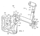
- FIG. 3 is an illustration of an example position sensor.
- FIG. 4 is an exploded view of the example position sensor of FIG. 3 .
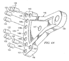
- FIG. 4A is a further exploded view of an example magnet array holder of the example position sensor in FIG. 4 .
- FIG. 5 is an illustration of an arm assembly and a magnet array of another example position sensor.
- FIG. 6 is an illustration of an arm assembly, sensor and magnet array holder of another example position sensor.
- FIG. 7 is a schematic illustration of an alternative coupling between a rotatable arm assembly of a magnetic position sensor and a sliding-stem actuator.
- the example apparatus to determine the position of an actuator described herein may be utilized for sensing or measuring displacement in various types of actuators. Additionally, while the examples described herein are described in connection with the control of product flow for the industrial processing industry, the examples described herein may be more generally applicable to a variety of process control operations for different purposes.
- FIG. 3 is an illustration of an example position sensor 100.
- the example position sensor 100 includes an arm assembly 110, a mounting bracket 120, a controller housing 130 and a sensor 160.
- the controller housing 130 is attached to the mounting bracket 120.
- the arm assembly 110 includes an actuation arm 112 having an opening 113 and an engagement part or roller 114, an alignment arm 116, an axle assembly 118, and a magnet array holder 140.
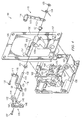
- FIG. 4 is an exploded view of the example position sensor 100 of FIG. 3 .
- the arm assembly 110 has the roller 114 attached at the distal end of the actuation arm 112 but can also be attached at the opening 113 if the amount of rotation of the actuation arm 112 is to be changed to enable the example position sensor 100 to be used with a different size or type of actuator.
- the axle assembly 118 includes an axle 119 that, when assembled, is welded to the actuation arm 112, and a pair of bearings 121.
- Axle end 122 includes a snap ring 123 to retain a torsion spring 124 on the axle 119.
- An axle end 126 extends through an opening 129 in the alignment arm 116.
- the alignment arm 116 includes an angled end 117 attached securely by a screw 131 to the actuation arm 112.
- a flange end 133 of the alignment arm 116 includes the opening 129 through which extends the axle end 126 to position the flange end 133 at the actuation arm 112.
- the flange end 133 of the alignment arm 116 also includes a threaded opening 135 to receive a screw 137.
- the example magnet array holder 140 is sector-shaped and has an opening 142 in a narrow sector end 144 to receive the axle end 126, and a larger sector end 146 has an opening 147 to receive the screw 137.
- the sector-shaped magnet array holder 140 is secured to and held in alignment with the flange end 133 of the alignment arm 116 by the reception of the axle end 126 in the opening 142 and the reception of the screw 137 in the openings 147 and 135.
- the magnet array holder 140 has a plurality of openings 148a-e located between double openings 149 and 151.
- Each of the openings 148a, 148b, 148d and 148e has fixed therein a cylindrically-shaped discrete magnet 155.
- Each of the openings of the double openings 149 and 151 has a discrete magnet 155 located therein.
- the opening 148c does not contain a magnet.
- the example sector-shaped magnet array holder 140 carries eight magnets 155, which create a rotary flux source 170.
- other numbers of magnets and array holders of other shapes may be used to create a suitable flux source such as the rotary flux source 170.
- the magnets 155 in the openings 149, 148a and 148b located above the opening 148c are arranged so that the flux source 170 changes induction from a high value to a low value as the magnet array holder 140 rotates from the double opening 149 to the opening 148b.
- the induction at the opening 148c is zero due to the absence of a magnet.
- the induction of the flux source 170 increases from a low value to a high value as the magnet array holder 140 rotates from the opening 148d to the double opening 151.
- both the amount and the direction of rotation of the magnet array holder 140 relative to the opening 148c can be determined from signals communicated by the position sensor 100.
- the mounting bracket 120 includes an outer flange 150, a laterally extending axle housing 156 with an opening 156a, receptacles 157, and a central opening 158.
- a plurality of holes are shown in the outer flange 150 to facilitate the attachment of the bracket 120 by way of screws or bolts to an actuator (not shown)
- the bracket 120 may be attached to an actuator by numerous other securing methods such as welding, releasable clips, hinge and lock, adhesive, etc.
- the receptacles 157 each have in their opposite side a threaded opening.
- the controller housing 130 may contain a valve controller (not shown).
- the housing 130 includes screws 162 aligned for reception in the not-shown threaded openings in the receptacles 157 of the mounting bracket 150.
- the sensor 160 is mounted in an opening 161 in a portion of the housing 130.
- the sensor 160 has a U-shaped flux-gathering pole piece 163 with forks 164. Referring to FIGS. 3 , 4 and 4A , the position sensor 100 has a null position, which occurs when the opening 148c of the magnet array holder 140 is located between the forks 164 of the pole piece 163. Although the position sensor 100 of FIGS.
- 3 , 4 and 4A is illustrated as a Hall Effect type of sensor, it is contemplated that other types of magnetic flux sensors, such as magneto-resistive, giant magneto-resistive bridge, or flux gate, may be utilized in the position sensor 100.
- magnetic flux sensors such as magneto-resistive, giant magneto-resistive bridge, or flux gate, may be utilized in the position sensor 100.
- the controller housing 130 is attached to the mounting bracket 120 by threading the screws 162 into the threaded openings of the receptacles 157.
- the sensor 160 is received within the opening 158 in the bracket 150.
- other securing methods may be used to attach the controller housing 130 to the mounting bracket 120.
- the position sensor 100, the mounting bracket 120, and the controller housing 130 are shown assembled for operation.
- the controller housing 130 has been attached to the mounting bracket 120.
- the axle 119 and the bearings 121 of the axle assembly 110 are received rotatably in the opening 156a of the laterally extending axle housing 156 (see FIG. 4 ).
- the sector-shaped magnet array holder 140 is attached to the alignment arm 116 of the arm assembly 110.
- the controller housing 130 positions the U-shaped flux-gathering pole piece 163 ( FIG. 4 ) of the sensor 160 perpendicular to the axis of rotation of the axle 119, which is received rotatably in the opening 156a of the axle housing 156.
- the rotatable flux source 170 is positioned to rotate about thirty degrees between the forks 164 of the pole piece 163.
- the position sensor 100 is operated by movable engagement of the engagement part or the roller 114 of the arm assembly 110 with a surface at a slope on a movable member of an actuator such as, for example, the sloped surface cam member 66 of the movable valve stem 64 in FIG. 1 , or the ramped or sloped surface cam member 76 of the movable valve stem 74 in FIG. 2 .
- the roller 114 is not fixedly positioned relative to the movable member such as the sloped surface cam member 66 or the ramped or sloped surface cam member 76.
- the movable engagement between the roller 114 and the movable member of an actuator may include any kind of engagement so that movement is accomplished between parts non-fixedly engaging one another such as, for example, by rolling, sliding, bearing, deflection, etc.
- the roller 114 is shown attached to the same side of the actuation arm 112 as the alignment arm 116, the roller 114 can be attached to the opposite side of the actuation arm 112 to accommodate engagement with a movable member of another actuator.
- the position sensor 100 provides a linear relationship between the rotary travel of the magnet array holder 140 and the output of the sensor 160, which is communicated as an electrical signal to the valve controller (not shown) at the controller housing 130.
- the not-shown valve controller communicates with a process control computer (not shown), which determines the position of a valve member operated by the actuator.
- the process control computer can apply any appropriate corrective action or a new command signal to the valve controller and the actuator to change the position of the valve member.
- the two magnets 155 located in each of the double openings 149 and 151 provide an end point effect for the position sensor 100.
- the example position sensor 100 senses a significant change in induction of the magnets 155 at one of the double openings 149 or 151.
- the example position sensor 100 communicates with the valve controller and the process control computer.
- the process control computer recognizes the significant change in induction of the flux source 170 as indicating that the position sensor 100 is at an end point of rotation (e.g., the magnets 155 in either of the double openings 149 or 151 are located between the forks 164 of the pole piece 163), which corresponds to an end point in the displacement of the valve member.
- the process control computer recognizes the significant change in induction of the flux source 170 as indicating that the position sensor 100 is at an end point of rotation (e.g., the magnets 155 in either of the double openings 149 or 151 are located between the forks 164 of the pole piece 163), which corresponds to an end point in the displacement of the valve member.
- the process control computer recognizes the significant change in induction of the flux source 170 as indicating that the position sensor 100 is at an end point of rotation (e.g., the magnets 155 in either of the double openings 149 or 151 are located between the forks 164 of the pole piece 163), which corresponds to
- FIG. 5 is an illustration of an arm assembly and a magnet array of another example position sensor 200.
- the example position sensor 200 provides an alternative configuration for mounting an arm assembly 210 and a rotatable magnet array holder 240.
- the example position sensor 200 includes the arm assembly 210, an axle 218, a controller housing 230, the magnet array holder 240, and discrete magnets 255.
- the arm assembly 210 includes an actuation arm 212 having an opening 213 and an engagement part or roller 214, and is fixed to the axle 218.
- the axle 218 includes a pair of axle extensions 219 having bearings 221.
- the axle 218 is fixed to the rotatable magnet array holder 240 aligned with a sensor 260.
- the discrete magnets 255 of the rotatable magnet holder 240 provide a rotary flux source 270.
- An axle end 222 includes a torsion spring 224 on the axle extension 219.
- a pair of stationary extensions 230 and 231 each have an opening (not shown) receiving a respective one of the bearings 221 on a respective one of the axle extensions 219.
- the stationary extensions 230 and 231 may be part of the controller housing 232 or a housing mounting bracket (not shown), or any other type of stationary housing member suitable for supporting the stationary extensions 230 and 231.
- the magnet array holder 240 is positioned between forks 264 of a U-shaped flux-gathering pole piece 263 of the sensor 260.
- the position sensor 200 in FIG. 5 operates similarly by a movable engagement of the roller 214 of the arm assembly 210 with a movable member of an actuator.
- the magnet array holder 240 and the discrete magnets 255 rotate relative to the sensor 260.
- the flux source 270 changes as the discrete magnets 255 rotate to cause the sensor 260 to communicate an electrical signal to a valve controller (not shown).
- FIG. 6 is an illustration of an arm assembly, sensor and magnet array holder of another example position sensor 275.
- the example position sensor 275 is an alternative configuration providing a rotatable sensor 280 and a stationary magnet array holder 290.
- the example position sensor 275 includes the arm assembly 210, the roller 214, the axle 218, and the stationary extensions 230 and 231 illustrated in FIG. 5 .
- the example position sensor 275 further includes the rotatable sensor 280 fixedly mounted to the axle 218 of the arm assembly 210, and a stationary magnet array holder 290 fixedly mounted to a part of a controller housing 297.
- the stationary magnet array holder 290 has discrete magnets 295 providing a stationary flux source 296.
- the stationary magnet array holder 290 is positioned between the forks 284 of a U-shaped flux-gathering pole piece 283 of the rotatable sensor 280.
- the position sensor 275 in FIG. 6 operates similarly by a movable engagement of the roller 214 of the arm assembly 210 with a movable member of an actuator.
- the rotatable sensor 280 rotates relative to the stationary magnet array holder 290 and the discrete magnets 295.
- the flux source 296 changes as the rotatable sensor 280 rotates to cause the rotatable sensor 280 to communicate an electrical signal to a valve controller (not shown).
- FIG. 7 is a schematic illustration of an alternative arm assembly 310 of a magnetic position sensor (not shown) coupled to a movable valve stem 364 of a sliding-stem actuator 360.
- the sliding-stem actuator 360 includes a piston 362 attached to the movable valve stem 364, which has an engagement part or pin 365.
- the arm assembly 310 of the magnetic position sensor includes an actuation arm 312 having a slot or a guide way 314 slidingly receiving the pin 365 to provide a sloped surface at the actuation ann 312.
- the actuation arm 312 rotates about a pivot axis 318, and the actuation arm 312 is connected to one of a magnetic flux sensor or a magnetic flux source (not shown) such as, for example, those previously described herein and in FIGS. 3-6 , or the actuation arm 312 may be connected by linkage to a single magnet rotary position sensor such as, for example, the rotary position sensor having single magnet flux source disclosed in commonly-owned US Patents 6,909,281 B2 and 7,005,847 B2 .
- the piston 362 moves downwardly to displace the movable valve stem 364 in the direction of arrow 350.
- the pin 365 on the movable valve stem 364 moves downwardly with the stem 364, the pin 365 slides in the guide way 314 and rotates the actuation arm 312 to operate the magnetic position sensor.
- the guide way 314 is illustrated as a through opening, the guide way 314 may be implemented using other sliding or guiding engagements such as, for example, a pin and parallel surfaces, a rotatable pin in a trough or trench, etc.
Landscapes
- Engineering & Computer Science (AREA)
- General Engineering & Computer Science (AREA)
- Mechanical Engineering (AREA)
- Measurement Of Length, Angles, Or The Like Using Electric Or Magnetic Means (AREA)
- Indication Of The Valve Opening Or Closing Status (AREA)
- Valve Device For Special Equipments (AREA)
- Transmission And Conversion Of Sensor Element Output (AREA)
- Magnetically Actuated Valves (AREA)
- Control Of Position Or Direction (AREA)
Claims (15)
- Positionssensor eines stellgliedbetätigten Ventilsystems, Folgendes aufweisend:ein Gehäuse (130), um ein Element, einen Magnetflusssensor (160) oder eine Magnetflussquelle (170) zu haltern, um Veränderungen in einem Magnetfeld zu erfassen, die sich aus einer relativen Verschiebung zwischen dem Magnetflusssensor und der Magnetflussquelle ergeben;einen Betätigungsarm (112), um das jeweils andere Element, den Magnetflusssensor oder die Magnetflussquelle zu haltern, um die relative Verschiebung zwischen dem Magnetflusssensor und der Magnetflussquelle zu ermöglichen, dadurch gekennzeichnet, dass der Betätigungsarm (112) drehbar ist, wobei der drehbare Betätigungsarm eine geneigte Fläche oder ein Eingriffsteil (114) aufweist, um die andere geneigte Fläche oder das andere Eingriffsteil, das durch ein bewegliches Teil eines Stellglieds des stellgliedbetätigten Ventilsystems gehaltert ist, beweglich in Eingriff zu nehmen, undeine drehbare Kupplung zwischen dem Betätigungsarm und dem Gehäuse.
- Positionssensor nach Anspruch 1, wobei der Magnetflusssensor (160) nahe der Magnetflussquelle vom Gehäuse gehaltert ist, und wobei die Magnetflussquelle (170) vom drehbaren Betätigungsarm drehbar positioniert wird.
- Positionssensor nach Anspruch 2, wobei die Magnetflussquelle (170) einen bogenförmigen Abschnitt aufweist, der eine Vielzahl von einzelnen Magneten (155) enthält.
- Positionssensor nach Anspruch 3, wobei die Magnetflussquelle ein Paar einzelner Magnete an im Wesentlichen derselben Winkelposition an entgegengesetzten Enden des bogenförmigen Abschnitts enthält.
- Positionssensor nach Anspruch 4, wobei ein Mittelabschnitt (148c) des bogenförmigen Abschnitts über keinen einzelnen Magneten verfügt.
- Positionssensor nach Anspruch 2, wobei der drehbare Betätigungsarm einen Ausrichtungsarm (116) umfasst, und die Magnetflussquelle einen Magnetflussquellenhalter (140) umfasst, der vom Ausrichtungsarm gehaltert ist.
- Positionssensor nach Anspruch 6, wobei der Ausrichtungsarm (116) am Betätigungsarm (112) befestigt ist und eine Öffnung umfasst, um eine Achse aufzunehmen.
- Positionssensor nach Anspruch 1, wobei das Gehäuse (130) eine Achslagerung (156) umfasst, und der drehbare Betätigungsarm (112) eine Achse (119) umfasst, die drehbar von der Achslagerung aufgenommen werden soll.
- Positionssensor nach Anspruch 1, wobei das Eingriffsteil (114) eine Rolle am drehbaren Betätigungsarm ist und drehbar an der Fläche angreift.
- Positionssensor nach Anspruch 1, wobei die Fläche Teil einer Führungsbahn (314) ist, und das Eingriffsteil ein Stift (365) ist, der in der Führungsbahn aufgenommen werden soll, um den Betätigungsarm (312) zu drehen.
- Positionssensor nach Anspruch 1, wobei die Fläche eine Nockenfläche des beweglichen Teils ist.
- Positionssensor nach Anspruch 11, wobei die Nockenfläche eine gekrümmte Fläche und/oder eine geneigte Fläche umfasst.
- Positionssensor nach Anspruch 1, wobei die Magnetflussquelle (170) aufweist:einen bogenförmigen Abschnitt, der ein Paar von Öffnungen (149, 151) an jedem Ende des bogenförmigen Abschnitts, die in Bezug auf einen bogenförmigen Bewegungsweg des bogenförmigen Abschnitts symmetrisch angeordnet sind, und eine Vielzahl von Öffnungen (148a - 148e) umfasst, die entlang des bogenförmigen Bewegungswegs des bogenförmigen Abschnitts zwischen dem Paar von Öffnungen beabstandet angeordnet sind;eine Vielzahl von einzelnen Magneten (155), die in der Vielzahl von Öffnungen angeordnet ist; undein Paar von einzelnen Magneten (155), die in jedem der Paare von Öffnungen angeordnet sind, wobei jedes Paar von einzelnen Magneten eine im Wesentlichen erhöhte Induktion in Bezug auf die Vielzahl von Magneten bereitstellt, um einen längsten Bewegungsweg des bogenförmigen Abschnitts anzuzeigen.
- Positionssensor nach Anspruch 13, wobei der Magnetflusssensor (160) aufweist:ein Paar von gabelförmigen Teilen, um ein U-förmiges, Fluss-erfassendes Polteil zu bilden,wobei die Magnetflussquelle zwischen dem Paar von gabelförmigen Teilen positioniert ist.
- Positionssensor nach Anspruch 13, wobei jeder Magnet (155) von der Vielzahl von einzelnen Magneten eine andere Feldstärke hat.
Applications Claiming Priority (2)
| Application Number | Priority Date | Filing Date | Title |
|---|---|---|---|
| US11/518,784 US7609056B2 (en) | 2006-09-11 | 2006-09-11 | Apparatus to determine the position of an actuator |
| PCT/US2007/077218 WO2008033675A2 (en) | 2006-09-11 | 2007-08-30 | Apparatus to determine the position of an actuator |
Publications (2)
| Publication Number | Publication Date |
|---|---|
| EP2061984A2 EP2061984A2 (de) | 2009-05-27 |
| EP2061984B1 true EP2061984B1 (de) | 2010-09-29 |
Family
ID=39092060
Family Applications (1)
| Application Number | Title | Priority Date | Filing Date |
|---|---|---|---|
| EP20070841612 Not-in-force EP2061984B1 (de) | 2006-09-11 | 2007-08-30 | Vorrichtung zur bestimmung der position eines aktuators |
Country Status (11)
| Country | Link |
|---|---|
| US (1) | US7609056B2 (de) |
| EP (1) | EP2061984B1 (de) |
| JP (1) | JP5244107B2 (de) |
| CN (1) | CN101512203B (de) |
| AR (1) | AR062722A1 (de) |
| BR (1) | BRPI0715902A2 (de) |
| CA (1) | CA2662802C (de) |
| DE (1) | DE602007009552D1 (de) |
| MX (1) | MX2009002424A (de) |
| RU (1) | RU2445539C2 (de) |
| WO (1) | WO2008033675A2 (de) |
Cited By (1)
| Publication number | Priority date | Publication date | Assignee | Title |
|---|---|---|---|---|
| DE102021129496A1 (de) | 2021-11-12 | 2023-05-17 | Samson Aktiengesellschaft | Sensorvorrichtung, Messanordnung und Verfahren zur Montage einer Sensorvorrichtung |
Families Citing this family (39)
| Publication number | Priority date | Publication date | Assignee | Title |
|---|---|---|---|---|
| US7444401B1 (en) | 2002-11-18 | 2008-10-28 | Arkion Systems Llc | Method and apparatus for inexpensively monitoring and controlling remotely distributed appliances |
| WO2008074024A2 (en) * | 2006-12-13 | 2008-06-19 | Stoneridge Control Devices, Inc. | Cylinder position sensor and cylinder incorporating the same |
| JP2011521263A (ja) * | 2008-05-19 | 2011-07-21 | ストーンリッジ・コントロール・デバイスィズ・インコーポレーテッド | シリンダ位置センサおよびシリンダ位置センサを組み込んだシリンダ |
| CA2997878A1 (en) | 2008-10-27 | 2010-05-06 | Mueller International, Llc | Infrastructure monitoring system and method |
| US8823509B2 (en) | 2009-05-22 | 2014-09-02 | Mueller International, Llc | Infrastructure monitoring devices, systems, and methods |
| CA3116787C (en) | 2010-06-16 | 2023-07-11 | Mueller International, Llc | Infrastructure monitoring devices, systems, and methods |
| US8596295B2 (en) * | 2010-06-16 | 2013-12-03 | Mueller International, Llc | Mechanical position indicator |
| US8833390B2 (en) | 2011-05-31 | 2014-09-16 | Mueller International, Llc | Valve meter assembly and method |
| US8960224B2 (en) * | 2011-08-18 | 2015-02-24 | Cameron International Corporation | Valve position translator |
| JP2014521908A (ja) * | 2011-08-19 | 2014-08-28 | ジェネラル イクイップメント アンド マニュファクチャリング カンパニー, インコーポレイテッド, ディー/ビー/エー トップワークス, インコーポレイテッド | バルブの位置を判定するための方法および装置 |
| NO333570B1 (no) * | 2011-10-12 | 2013-07-08 | Electrical Subsea & Drilling As | Anordning ved ventilaktuator med fjaerretur og framgangsmate for betjening av en ventil |
| US8660134B2 (en) | 2011-10-27 | 2014-02-25 | Mueller International, Llc | Systems and methods for time-based hailing of radio frequency devices |
| US8855569B2 (en) | 2011-10-27 | 2014-10-07 | Mueller International, Llc | Systems and methods for dynamic squelching in radio frequency devices |
| CA2872549C (en) | 2012-05-25 | 2021-04-13 | Mueller International, Llc | Position indicator for valves |
| US9097269B2 (en) * | 2012-06-04 | 2015-08-04 | Fisher Controls International, Llc | Bracket assemblies for use with actuators |
| US9423050B2 (en) * | 2013-04-09 | 2016-08-23 | Fisher Controls International Llc | Intelligent actuator and method of monitoring actuator health and integrity |
| JP5800207B2 (ja) * | 2013-05-10 | 2015-10-28 | 株式会社デンソー | 回転位置検出装置 |
| CN103363186A (zh) * | 2013-07-26 | 2013-10-23 | 常熟市华夏仪表有限公司 | 电气阀门定位器的轴反馈装置 |
| US9618136B2 (en) | 2013-09-16 | 2017-04-11 | Fisher Controls International Llc | Rotary valve position indicator |
| US9772046B2 (en) * | 2013-12-05 | 2017-09-26 | Badger Meter, Inc. | Method and apparatus for mounting a control valve positioner |
| US9494249B2 (en) | 2014-05-09 | 2016-11-15 | Mueller International, Llc | Mechanical stop for actuator and orifice |
| US9599502B2 (en) * | 2014-07-22 | 2017-03-21 | Fisher Controls International Llc | Magnetic field sensor feedback for diagnostics |
| US9565620B2 (en) | 2014-09-02 | 2017-02-07 | Mueller International, Llc | Dynamic routing in a mesh network |
| US9777855B2 (en) * | 2014-11-17 | 2017-10-03 | Regulator Technologies Tulsa, Llc | Pressure vacuum relief valve providing monitoring capabilities |
| US9945701B2 (en) * | 2015-07-17 | 2018-04-17 | Fisher Controls International Llc | Actuator bracket having a sensor |
| US20170307411A1 (en) * | 2016-04-22 | 2017-10-26 | KSR IP Holdings, LLC | Position sensor |
| US10240687B2 (en) | 2016-10-20 | 2019-03-26 | Fisher Controls International Llc | Methods and apparatus of testing a solenoid valve of an emergency valve via a positioner |
| US10041610B2 (en) * | 2016-10-20 | 2018-08-07 | Fisher Controls International Llc | Methods and apparatus of stabilizing a valve positioner when testing a solenoid valve |
| US10234058B2 (en) | 2016-10-20 | 2019-03-19 | Fisher Controls International Llc | Methods and apparatus of assessing a test of a solenoid valve via a positioner |
| US10466093B2 (en) | 2017-07-12 | 2019-11-05 | Sikorsky Aircraft Corporation | Failsafe electromechanical weight on wheels detection |
| US10711907B2 (en) | 2017-11-07 | 2020-07-14 | Black Diamond Engineering, Inc. | Line replaceable control valve positioner/controller system |
| US10865817B2 (en) * | 2018-10-10 | 2020-12-15 | Dresser, Llc | Compensating for orientation of a valve positioner on a valve assembly |
| DE102018217281A1 (de) * | 2018-10-10 | 2020-04-16 | Continental Teves Ag & Co. Ohg | Winkelsensor zum Erfassen eines Drehwinkels |
| US11174964B2 (en) * | 2018-10-29 | 2021-11-16 | Fisher Controls International Llc | Position transmitter assemblies for use with actuators |
| US11454334B1 (en) * | 2021-04-09 | 2022-09-27 | Dresser, Llc | Accuracy of control valves using a short-stroke position converter |
| US11536393B2 (en) | 2021-04-12 | 2022-12-27 | Fisher Controls International Llc | Travel feedback system |
| WO2023229651A1 (en) * | 2022-05-25 | 2023-11-30 | Dresser, Llc | Improving accuracy of control valves using a long-stroke position converter |
| WO2023229650A1 (en) * | 2022-05-25 | 2023-11-30 | Dresser, Llc | Improving accuracy of control valves using a short-stroke position converter |
| CN117386877B (zh) * | 2023-09-22 | 2024-08-30 | 安徽摩控科技有限公司 | 一种反馈机构和阀门定位器 |
Family Cites Families (44)
| Publication number | Priority date | Publication date | Assignee | Title |
|---|---|---|---|---|
| SU513205A1 (ru) * | 1974-05-13 | 1976-05-05 | Научно-Производственное Объединение "Киеварматура" | Датчик положени затвора клапана |
| JPS6219923Y2 (de) * | 1980-12-16 | 1987-05-21 | ||
| JPS5981511A (ja) * | 1982-11-01 | 1984-05-11 | Citizen Watch Co Ltd | 回転軸位置検出装置 |
| JPS6049231U (ja) * | 1983-09-12 | 1985-04-06 | 三國工業株式会社 | 気化器の絞弁開度検出センサ取付装置 |
| JPS60170719A (ja) * | 1984-02-15 | 1985-09-04 | Aisin Seiki Co Ltd | 回転角度センサ |
| JPS6115309U (ja) * | 1984-06-27 | 1986-01-29 | 世紀東急工業株式会社 | 舗装路面の凹凸測定装置 |
| JPS61175545U (de) * | 1985-04-22 | 1986-11-01 | ||
| JPS61290303A (ja) * | 1985-06-18 | 1986-12-20 | Sanshin Ind Co Ltd | 船舶用推進ユニツトの傾斜角検出装置 |
| US4746772A (en) * | 1986-09-23 | 1988-05-24 | Fisher Controls International, Inc. | Adjustable position indicating apparatus |
| JPH0416892Y2 (de) * | 1986-11-13 | 1992-04-15 | ||
| SE462811B (sv) * | 1989-05-09 | 1990-09-03 | Hans Karlsson | Anordning foer omvandling av en fram- och aatergaaende roerelse till en roterande roerelse |
| JPH0744972Y2 (ja) * | 1989-12-25 | 1995-10-11 | 株式会社緑測器 | 無接触直線変位センサ |
| TW248544B (de) * | 1991-04-03 | 1995-06-01 | Torrington Co | |
| JP2516227Y2 (ja) * | 1991-09-10 | 1996-11-06 | 国産電機株式会社 | 内燃機関用スロットル開度検出装置 |
| JPH0735961B2 (ja) * | 1991-09-11 | 1995-04-19 | 株式会社エム・システム技研 | 変位検出用差動トランス及び角度検出器 |
| US5164668A (en) * | 1991-12-06 | 1992-11-17 | Honeywell, Inc. | Angular position sensor with decreased sensitivity to shaft position variability |
| JP3206204B2 (ja) * | 1992-05-22 | 2001-09-10 | 株式会社デンソー | スロットルポジションセンサ |
| JP2762356B2 (ja) * | 1996-09-13 | 1998-06-04 | 株式会社スリーエス | ポジショナーに於けるレンジ調整装置 |
| JPH10103562A (ja) * | 1996-09-24 | 1998-04-21 | Hitachi Plant Eng & Constr Co Ltd | バルブ開閉度表示装置およびバルブ開閉度復旧方法 |
| US5933005A (en) * | 1997-07-29 | 1999-08-03 | Brunswick Corporation | Throttle position monitor with one stationary sensor and one movable sensor |
| JP2000234678A (ja) * | 1999-02-17 | 2000-08-29 | Dainippon Printing Co Ltd | コントロールバルブ部の開閉表示装置と表示装置付き弁体 |
| JP2001153260A (ja) * | 1999-11-30 | 2001-06-08 | Ishikawajima Harima Heavy Ind Co Ltd | 弁の開度検出機構 |
| DE10041095B4 (de) * | 1999-12-06 | 2015-11-12 | Robert Bosch Gmbh | Vorrichtung zur Messung eines Winkels und/oder eines Drehmomentes eines drehbaren Körpers |
| DE10016636A1 (de) | 2000-04-04 | 2001-10-18 | Siemens Ag | Stellungsregler, insbesondere für ein durch einen Antrieb betätigbares Ventil |
| US6211794B1 (en) * | 2000-04-06 | 2001-04-03 | Borgwarner | Analog rotary position sensor |
| US6424928B1 (en) * | 2000-06-15 | 2002-07-23 | Eim Company, Inc. | Absolute position detector interpreting abnormal states |
| JP2002022403A (ja) * | 2000-07-13 | 2002-01-23 | Tokyo Keiso Co Ltd | 変位検出器および変位検出方法 |
| US6753680B2 (en) * | 2000-11-29 | 2004-06-22 | Ronald J. Wolf | Position sensor |
| JP3757118B2 (ja) * | 2001-01-10 | 2006-03-22 | 株式会社日立製作所 | 非接触式回転位置センサ及び非接触式回転位置センサを有する絞弁組立体 |
| US6382226B1 (en) | 2001-04-17 | 2002-05-07 | Fisher Controls International, Inc. | Method for detecting broken valve stem |
| JP3877998B2 (ja) * | 2001-11-05 | 2007-02-07 | 株式会社山武 | 角度センサの温度情報検出装置および位置検出装置 |
| US6784659B2 (en) * | 2001-12-05 | 2004-08-31 | Honeywell International Inc. | Magnetoresistive speed and direction sensing method and apparatus |
| JP3831657B2 (ja) * | 2001-12-06 | 2006-10-11 | アルプス電気株式会社 | 回転位置検出センサ |
| DE20200302U1 (de) * | 2002-01-10 | 2002-03-28 | Ab Elektronik Gmbh, 59368 Werne | Drehwinkelsensor |
| JP2004012299A (ja) * | 2002-06-06 | 2004-01-15 | Nippon Soken Inc | 同期回転機用回転角度検出装置 |
| US7023200B2 (en) * | 2002-06-18 | 2006-04-04 | Siemens Vdo Automotive Corporation | Non-contacting large angle rotary position sensor for rotating shaft |
| US6909281B2 (en) * | 2002-07-03 | 2005-06-21 | Fisher Controls International Llc | Position sensor using a compound magnetic flux source |
| US7219691B2 (en) | 2003-02-07 | 2007-05-22 | Fisher Controls International Llc | Control valve positioner mounting system |
| JP4262492B2 (ja) * | 2003-02-18 | 2009-05-13 | 北海道石油共同備蓄株式会社 | バルブ開閉装置 |
| CA2513831C (en) * | 2003-02-21 | 2010-12-07 | Fisher Controls International Llc | Magnetic position sensor with integrated hall effect switch |
| DE10360434B4 (de) | 2003-12-22 | 2006-12-07 | Samson Ag | Anordnung, Positionssensor, Einrichtung zum Regeln, Antrieb und Verfahren zum Erfassen der Stellung eines antreibbaren Bauteils |
| US6992478B2 (en) * | 2003-12-22 | 2006-01-31 | Cts Corporation | Combination hall effect position sensor and switch |
| JP4525101B2 (ja) * | 2004-02-17 | 2010-08-18 | アイシン精機株式会社 | 変位センサ装置 |
| JP4184350B2 (ja) * | 2005-01-26 | 2008-11-19 | 株式会社東京測器研究所 | ホイールの6分力測定システム |
-
2006
- 2006-09-11 US US11/518,784 patent/US7609056B2/en active Active
-
2007
- 2007-08-30 BR BRPI0715902-1A2A patent/BRPI0715902A2/pt active Search and Examination
- 2007-08-30 MX MX2009002424A patent/MX2009002424A/es active IP Right Grant
- 2007-08-30 DE DE200760009552 patent/DE602007009552D1/de active Active
- 2007-08-30 RU RU2009112050/06A patent/RU2445539C2/ru not_active IP Right Cessation
- 2007-08-30 JP JP2009527501A patent/JP5244107B2/ja not_active Expired - Fee Related
- 2007-08-30 EP EP20070841612 patent/EP2061984B1/de not_active Not-in-force
- 2007-08-30 WO PCT/US2007/077218 patent/WO2008033675A2/en active Application Filing
- 2007-08-30 CN CN200780033385XA patent/CN101512203B/zh not_active Expired - Fee Related
- 2007-08-30 CA CA 2662802 patent/CA2662802C/en not_active Expired - Fee Related
- 2007-09-10 AR ARP070103985 patent/AR062722A1/es active IP Right Grant
Cited By (1)
| Publication number | Priority date | Publication date | Assignee | Title |
|---|---|---|---|---|
| DE102021129496A1 (de) | 2021-11-12 | 2023-05-17 | Samson Aktiengesellschaft | Sensorvorrichtung, Messanordnung und Verfahren zur Montage einer Sensorvorrichtung |
Also Published As
| Publication number | Publication date |
|---|---|
| AR062722A1 (es) | 2008-11-26 |
| US7609056B2 (en) | 2009-10-27 |
| WO2008033675A3 (en) | 2008-05-08 |
| DE602007009552D1 (de) | 2010-11-11 |
| BRPI0715902A2 (pt) | 2013-07-23 |
| CA2662802A1 (en) | 2008-03-20 |
| RU2445539C2 (ru) | 2012-03-20 |
| JP2010502989A (ja) | 2010-01-28 |
| CN101512203A (zh) | 2009-08-19 |
| JP5244107B2 (ja) | 2013-07-24 |
| WO2008033675A2 (en) | 2008-03-20 |
| EP2061984A2 (de) | 2009-05-27 |
| US20080061769A1 (en) | 2008-03-13 |
| CN101512203B (zh) | 2011-05-04 |
| CA2662802C (en) | 2011-05-03 |
| MX2009002424A (es) | 2009-03-20 |
| RU2009112050A (ru) | 2010-10-20 |
Similar Documents
| Publication | Publication Date | Title |
|---|---|---|
| EP2061984B1 (de) | Vorrichtung zur bestimmung der position eines aktuators | |
| CA2512996C (en) | Control valve positioner mounting system | |
| US7044444B2 (en) | Actuator element with position detection | |
| EP2035733B1 (de) | Verfahren und drehventilstellglied | |
| EP2470815B1 (de) | Ventilkalibrierung | |
| CN1244851C (zh) | 用于控制设备的塞和座定位系统 | |
| EP3710906B1 (de) | Positionssensoren für ventilsysteme sowie verwandte anordnungen, systeme und verfahren | |
| US20170328493A1 (en) | Valve and a method of operating a valve | |
| US10066761B1 (en) | Valve assembly and limit switch assembly therefor | |
| US20110100469A1 (en) | Flow control valve | |
| MXPA05000243A (es) | Sensor de posicion que utiliza una fuente de flujo magnetico de compuesto. | |
| CA2134398C (en) | Device to indicate operating state of a linear actuation valve | |
| CA3160357A1 (en) | Improving accuracy of control valves using a short-stroke position converter | |
| US9772046B2 (en) | Method and apparatus for mounting a control valve positioner | |
| CN109780296A (zh) | 一种直线电机阀门定位器 | |
| CN211574386U (zh) | 用于与致动器的致动器杆一起使用的位置变送器组件 | |
| US7057369B2 (en) | System and device for regulating the position of a drivable component and drive therefor | |
| KR101604338B1 (ko) | 판스프링을 이용한 부하인가장치 및 그 작동방법 | |
| CN218152647U (zh) | 线性行程反馈组件和线性行程反馈系统 | |
| WO2023229651A1 (en) | Improving accuracy of control valves using a long-stroke position converter | |
| WO2023229650A1 (en) | Improving accuracy of control valves using a short-stroke position converter |
Legal Events
| Date | Code | Title | Description |
|---|---|---|---|
| PUAI | Public reference made under article 153(3) epc to a published international application that has entered the european phase |
Free format text: ORIGINAL CODE: 0009012 |
|
| 17P | Request for examination filed |
Effective date: 20090327 |
|
| AK | Designated contracting states |
Kind code of ref document: A2 Designated state(s): AT BE BG CH CY CZ DE DK EE ES FI FR GB GR HU IE IS IT LI LT LU LV MC MT NL PL PT RO SE SI SK TR |
|
| AX | Request for extension of the european patent |
Extension state: AL BA HR MK RS |
|
| R17D | Deferred search report published (corrected) |
Effective date: 20080508 |
|
| RIN1 | Information on inventor provided before grant (corrected) |
Inventor name: JUNK, KENNETH W. Inventor name: HURD, RONALD FRANCIS Inventor name: LOVELL, MICHEL KEN Inventor name: PAULLUS, STEVEN BURL |
|
| DAX | Request for extension of the european patent (deleted) | ||
| GRAP | Despatch of communication of intention to grant a patent |
Free format text: ORIGINAL CODE: EPIDOSNIGR1 |
|
| GRAS | Grant fee paid |
Free format text: ORIGINAL CODE: EPIDOSNIGR3 |
|
| GRAA | (expected) grant |
Free format text: ORIGINAL CODE: 0009210 |
|
| AK | Designated contracting states |
Kind code of ref document: B1 Designated state(s): DE FI FR GB SE |
|
| REG | Reference to a national code |
Ref country code: GB Ref legal event code: FG4D |
|
| REF | Corresponds to: |
Ref document number: 602007009552 Country of ref document: DE Date of ref document: 20101111 Kind code of ref document: P |
|
| REG | Reference to a national code |
Ref country code: SE Ref legal event code: TRGR |
|
| PLBE | No opposition filed within time limit |
Free format text: ORIGINAL CODE: 0009261 |
|
| STAA | Information on the status of an ep patent application or granted ep patent |
Free format text: STATUS: NO OPPOSITION FILED WITHIN TIME LIMIT |
|
| REG | Reference to a national code |
Ref country code: DE Ref legal event code: R097 Ref document number: 602007009552 Country of ref document: DE Effective date: 20110630 |
|
| REG | Reference to a national code |
Ref country code: FR Ref legal event code: PLFP Year of fee payment: 10 |
|
| REG | Reference to a national code |
Ref country code: FR Ref legal event code: PLFP Year of fee payment: 11 |
|
| REG | Reference to a national code |
Ref country code: FR Ref legal event code: PLFP Year of fee payment: 12 |
|
| PGFP | Annual fee paid to national office [announced via postgrant information from national office to epo] |
Ref country code: FI Payment date: 20190828 Year of fee payment: 13 Ref country code: SE Payment date: 20190828 Year of fee payment: 13 Ref country code: DE Payment date: 20190828 Year of fee payment: 13 Ref country code: FR Payment date: 20190826 Year of fee payment: 13 |
|
| PGFP | Annual fee paid to national office [announced via postgrant information from national office to epo] |
Ref country code: GB Payment date: 20190827 Year of fee payment: 13 |
|
| REG | Reference to a national code |
Ref country code: DE Ref legal event code: R119 Ref document number: 602007009552 Country of ref document: DE |
|
| REG | Reference to a national code |
Ref country code: FI Ref legal event code: MAE |
|
| REG | Reference to a national code |
Ref country code: SE Ref legal event code: EUG |
|
| GBPC | Gb: european patent ceased through non-payment of renewal fee |
Effective date: 20200830 |
|
| PG25 | Lapsed in a contracting state [announced via postgrant information from national office to epo] |
Ref country code: FI Free format text: LAPSE BECAUSE OF NON-PAYMENT OF DUE FEES Effective date: 20200830 |
|
| PG25 | Lapsed in a contracting state [announced via postgrant information from national office to epo] |
Ref country code: SE Free format text: LAPSE BECAUSE OF NON-PAYMENT OF DUE FEES Effective date: 20200831 |
|
| PG25 | Lapsed in a contracting state [announced via postgrant information from national office to epo] |
Ref country code: DE Free format text: LAPSE BECAUSE OF NON-PAYMENT OF DUE FEES Effective date: 20210302 Ref country code: FR Free format text: LAPSE BECAUSE OF NON-PAYMENT OF DUE FEES Effective date: 20200831 |
|
| PG25 | Lapsed in a contracting state [announced via postgrant information from national office to epo] |
Ref country code: GB Free format text: LAPSE BECAUSE OF NON-PAYMENT OF DUE FEES Effective date: 20200830 |