EP2060246B1 - Skibrille - Google Patents
Skibrille Download PDFInfo
- Publication number
- EP2060246B1 EP2060246B1 EP08019827A EP08019827A EP2060246B1 EP 2060246 B1 EP2060246 B1 EP 2060246B1 EP 08019827 A EP08019827 A EP 08019827A EP 08019827 A EP08019827 A EP 08019827A EP 2060246 B1 EP2060246 B1 EP 2060246B1
- Authority
- EP
- European Patent Office
- Prior art keywords
- ski goggles
- shield
- frame
- air
- pane
- Prior art date
- Legal status (The legal status is an assumption and is not a legal conclusion. Google has not performed a legal analysis and makes no representation as to the accuracy of the status listed.)
- Not-in-force
Links
Images


Classifications
-
- A—HUMAN NECESSITIES
- A61—MEDICAL OR VETERINARY SCIENCE; HYGIENE
- A61F—FILTERS IMPLANTABLE INTO BLOOD VESSELS; PROSTHESES; DEVICES PROVIDING PATENCY TO, OR PREVENTING COLLAPSING OF, TUBULAR STRUCTURES OF THE BODY, e.g. STENTS; ORTHOPAEDIC, NURSING OR CONTRACEPTIVE DEVICES; FOMENTATION; TREATMENT OR PROTECTION OF EYES OR EARS; BANDAGES, DRESSINGS OR ABSORBENT PADS; FIRST-AID KITS
- A61F9/00—Methods or devices for treatment of the eyes; Devices for putting-in contact lenses; Devices to correct squinting; Apparatus to guide the blind; Protective devices for the eyes, carried on the body or in the hand
- A61F9/02—Goggles
- A61F9/028—Ventilation means
Definitions
- the invention is directed to a goggle, comprising a frame and a lens arranged thereon and a tether and air inlet openings in the frame.
- the frame is designed to keep the pane at a distance from the user's eyes, i. between the inside of the lens and the face is a closed airspace. As a result, this space heats up and, due to the perspiration of the user, has a higher humidity than the environment, which in turn leads to fogging of the inside of the viewing window.
- Such misting can be counteracted by a corresponding coating on the one hand and by air inlet openings on the other hand, which ensure that an exchange of air between the moister, warmer interior and the ambient air takes place.
- a ski goggles with ventilation openings is for example from the US 3,395,406 known.
- the object of the invention is to counteract fogging of the inner side of the disk by optimizing this air exchange.
- a front of the disc superior shield is arranged, which has air inlet openings, wherein the shield is arranged at a distance from the frame such that air can flow through the air inlet openings and below the shield.
- the incoming air is directed through passage openings of the frame into the region between the rear side of the disc and the forehead of the user.
- a ski goggle 1 shown in the drawing comprises a frame 2, on which a viewing window 3 is arranged, and which is provided with a holding band 4.
- the tether 4 is connected to the frame 2 by means of a headband strap 31.
- the headband strap 31 is arranged in a lateral, peripheral region on the frame 2 and extends along the upper edge of the ski goggles 1.
- the headband strap 31 may be formed in a particularly appealing embodiment in a contrasting color to the frame 2. It is preferably made of plastic and / or metal.
- the frame 2 has a frame 3 which surrounds the disc 3 and from which extends approximately perpendicularly to the rear, onto the user's face to form a spacer section 6, on the rear side of which a facial contact web 7 extends along the upper edge.
- a shield 8 projecting forward over the frame 2 is arranged on the front side of the frame 2, which plate has a central air inlet opening 9 and two lateral air inlet openings 10.
- air flow for example in the form of wind or due to natural external air movements.
- the shield 8 protrudes in the middle region by at least 5 mm, in particular at least 10 mm, over the viewing window 3 of the ski goggles 1. It thus forms an air guiding device which specifically directs and / or diverts the air flowing onto the ski goggles 1.
- the shield 8 is preferably made of plastic and / or carbon and / or metal, in particular aluminum or titanium.
- the Durcblassö réelleen 9, 10 are formed at a distance from the front edge 12 of the shield 8 by bulges 13, 14.
- the bulges 13, 14 have a free height of at least 2 mm, in particular at least 5 mm. They have a lateral extent of at least 10 mm, in particular at least 20 mm.
- the lateral extent is preferably at least three times, in particular at least five times as large as the free height of the bulges 13,14, which gives them, inter alia, a particularly advantageous design.
- the passage openings 9, 10 are aligned in such a way that when using the ski goggles 1, air flowing in from the front can flow through them efficiently, that is, largely unrestrained.
- the frame 2 has passage openings 15 in the middle region on the upper side and 16, 17 in the edge regions.
- the passage openings 15, 16, 17 may be covered by air-permeable foam inserts 29.
- the foam inserts 29 are preferably interchangeable and / or washable.
- special recesses 30 are provided in the frame 2.
- the shield 8 forms a kind of roof over the passage openings 15, 16, 17.
- the passage openings 15, 16, 17 are at least partially covered by the shield 8. They are thus protected with attached glasses from above through the shield 8 against the ingress of rain and / or snow.
- the shield 8 is shaped and arranged so that it is slightly inclined downwards in the central region relative to the disk 3 as seen from the side.
- the shield 8 is preferably attachable to the frame 2. He has for this purpose a middle plug-in device 32 and each side plug-in devices 33.
- the Steckeiniliensen 32, 33 are with matching shots latched in the headband bracket 31.
- the shield 8 is thus easily removable if necessary.
- the shield 8 is arranged at such a distance from the frame 2 that an air inlet gap 37 is formed between them.
- the design and arrangement of the shield 8 leads to an air flow, as in 4 and 5 is shown.
- Fig. 4 It can be seen that air (air streams 21, 22) flows in above and below the shield 8 in the middle region. The air thus flows through the air inlet opening 9 and the air inlet gap 37. The incoming air is deflected by the shield 8 by approximately 90 °, so that it along the rear side 23 of the disc 3 flows along and thus prevents their fogging.
- the shield 8 has for this purpose in the central region on a front web 34, which is formed profiled wing like a wing.
- the web 34 has a flat tapered rear edge 19, which leads to a laminar flow as possible on the face of the user facing side of the web 34.
- the plate 8 has a central bulge 14 forming the rear web 35.
- the rear web 35 is located on the facial contact web 7 and thus prevents the escape of the air flow upwards. He is as well starting from the facial contact web 7 arranged slightly upwards at the top, which contributes to a particularly efficient deflection of the incoming air. This targeted deflection of the incoming air can be supported by a slightly curved and / or stepped design of the rear web 35.
- the rear web 35 is ensured that the incoming air is at least largely directed in the central region of the ski goggles 1 in the space between the disc 3 and the face of the user.
- the rear web 35 can be latched to the headband strap 31. He is in particular latched from below with the headband strap 31. He is thereby securely fixed and contributes to the secure fit of the attached shield 8 at the goggles 1 at.
- the lateral bulges 13 are each formed by a rear web 36 Fig. 5 It can be seen that the rear web 36 of the lateral bulge 13 is arranged at a distance from the facial contact web 7. Between the rear web 36 and the facial contact web 7, a slot 26 is formed. The entering in the lateral areas above and below the shield 8 air streams 24, 25 can thus escape through the slot 26 in front of the facial contact web 7 upwards.
- the Venturi effect As a result, due to the Venturi effect, a negative pressure is generated in the area behind the pane 3, so that the humid and warm air located there, as shown by the air streams 27, 28 in FIG Fig. 5 illustrated, is sucked through the passage openings 16,17, which also fogging of the disc 3 is prevented.
- the rear Bridge 36 in the region of the lateral bulges 13 a wing-like profiled training on.
- Such a design of the rear web 36 in the region of the lateral bulges 13 leads to a negative pressure on the upper side.
- the Venturi effect is amplified in the lateral regions of the ski goggles 1, thereby further improving the air circulation in the space between the disk 3 and the face of the user.
- the plate 8 protrudes beyond the pane 3, it simultaneously also acts as a sun visor against solar radiation incident from above and / or as rain protection.
Landscapes
- Health & Medical Sciences (AREA)
- Life Sciences & Earth Sciences (AREA)
- General Health & Medical Sciences (AREA)
- Biomedical Technology (AREA)
- Heart & Thoracic Surgery (AREA)
- Vascular Medicine (AREA)
- Ophthalmology & Optometry (AREA)
- Animal Behavior & Ethology (AREA)
- Engineering & Computer Science (AREA)
- Public Health (AREA)
- Veterinary Medicine (AREA)
- Eyeglasses (AREA)
- Gyroscopes (AREA)
- Crystals, And After-Treatments Of Crystals (AREA)
- Respiratory Apparatuses And Protective Means (AREA)
Description
- Die Erfindung richtet sich auf eine Skibrille, umfassend einen Rahmen und eine daran angeordnete Sichtscheibe sowie ein Halteband und Lufteinlassöffnungen im Rahmen.
- Der Rahmen ist so ausgestaltet, dass die Scheibe im Abstand zu den Augen des Benutzers gehalten wird, d.h. zwischen der Innenseite der Sichtscheibe und dem Gesicht ist ein abgeschlossener Luftraum. Dies führt dazu, dass dieser Raum sich erwärmt und aufgrund der Transpiration des Benutzers eine höhere Feuchtigkeit aufweist als die Umgebung, was wiederum zu einem Beschlagen der Innenseite der Sichtscheibe führt.
- Einem solchen Beschlagen kann man durch eine entsprechende Beschichtung einerseits und durch Lufteinlassöffnungen andererseits entgegenwirken, welche dafür sorgen, dass ein Luftaustausch zwischen dem feuchteren, wärmeren Innenraum und der Umgebungsluft stattfindet. Eine Skibrille mit Belüftungsöffnungen ist beispielsweise aus der
US 3,395,406 bekannt. - Hiervon ausgehend liegt der Erfindung die Aufgabe zugrunde, durch Optimierung dieses Luftaustausches dem Beschlagen der Scheibeninnenseite entgegenzuwirken.
- Diese Aufgabe wird erfindungsgemäß dadurch gelöst, dass oberhalb der Scheibe ein die Vorderseite der Scheibe überragender Schild angeordnet ist, welches Lufteinlassöffnungen aufweist, wobei der Schild im Abstand zum Rahmen derart angeordnet ist, dass Luft durch die Lufteinlassöffnungen und unterhalb des Schildes einströmen kann.
- Insbesondere ist mit Vorteil vorgesehen, dass im Mittelbereich die einströmende Luft durch Durchlassöffnungen des Rahmens in den Bereich zwischen der Hinterseite der Scheibe und der Stirn des Benutzers gelenkt wird.
- In den Randbereichen ist demgegenüber günstigerweise vorgesehen, dass die durch die Einlassöffnungen einströmende Luft oberhalb von Durchlassöffnungen im Rahmen zum Bereich hinter der Scheibe entlanggeführt und durch Auslassöffnungen an der Oberseite des Rahmens wieder herausgeführt wird.
- Durch diesen Luftstrom wird im Bereich hinter der Scheibe ein Unterdruck erzeugt, so dass aus diesem Bereich feuchte, warme Luft eingesaugt und nach außen mit herausgeführt wird.
- Besonders vorteilhafte Strömungsverhältnisse erhält man dadurch, dass das Schild mit der Scheibe einen Winkel von < als 90° einschließt.
- Nachfolgend wird die Erfindung anhand eines bevorzugten Ausführungsbeispiels in Verbindung mit der Zeichnung näher erläutert. Dabei zeigen:
-
Fig. 1 eine perspektivische Ansicht einer erfindungsgemäßen Skibrille, -
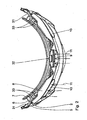
Fig. 2 eine Aufsicht der Skibrille, -
Fig. 3 eine Ansicht von vorne, -
Fig. 4 einen Schnitt längs der Linie IV-IV inFig. 3 und -
Fig. 5 einen Schnitt längs der Linie V-V inFig. 3 . - Eine in der Zeichnung dargestellte Skibrille 1 umfasst einen Rahmen 2 , an dem eine Sichtscheibe 3 angeordnet ist, und der mit einem Halteband 4 versehen ist. Das Halteband 4 ist mittels eines Kopfbandbügels 31 mit dem Rahmen 2 verbunden. Der Kopfbandbügel 31 ist in einem seitlichen, peripheren Bereich am Rahmen 2 angeordnet und erstreckt sich entlang der Oberkante der Skibrille 1. Der Kopfbandbügel 31 kann in einer besonders ansprechenden Ausführungsform in eine Kontrastfarbe zum Rahmen 2 ausgebildet sein. Es ist vorzugsweise aus Kunststoff und/oder Metall.
- Der Rahmen 2 weist einen die Scheibe 3 umgreifenden Rahmenabschnitt 5 auf, von welchem sich etwa senkrecht nach hinten weg, auf das Gesicht des Benutzers zu ein Abstandshalteabschnitt 6 wegerstreckt, an dessen Rückseite längs der Oberkante ein Gesichtsanlagesteg 7 verläuft.
- Oberhalb der Scheibe 3 ist an der Vorderseite des Rahmens 2 ein nach vorne über den Rahmen 2 vorstehender Schild 8 angeordnet, welcher eine zentrale Lufteinlassöffnung 9 und zwei seitliche Lufteinlassöffnungen 10 aufweist. Durch diese kann, wie durch die Pfeile 11 in
Fig. 2 angedeutet, Luft einströmen, z.B. in Form von Fahrtwind oder aufgrund natürlicher äußerer Luftbewegungen. Der Schild 8 steht im Mittelbereich um mindestens 5mm, insbesondere mindestens 10 mm über die Sichtscheibe 3 der Skibrille 1 vor. Er bildet somit eine Luftleiteinrichtung, welche die auf die Skibrille 1 anströmende Luft gezielt lenkt und/oder umlenkt. Der Schild 8 ist vorzugsweise aus Kunststoff und/oder Karbon und/oder Metall, insbesondere Aluminium oder Titan. - Die Durcblassöffnungen 9, 10 sind mit Abstand von der Vorderkante 12 des Schildes 8 durch Aufwölbungen 13, 14 ausgebildet. Die Aufwölbungen 13, 14 weisen eine freie Höhe von mindestens 2 mm, insbesondere mindestens 5 mm auf. Sie weisen eine laterale Erstreckung von mindestens 10 mm, insbesondere mindestens 20 mm auf. Hierbei ist die laterale Erstreckung vorzugsweise mindestens dreimal, insbesondere mindestens fünfmal so groß die die freie Höhe der Aufwölbungen 13,14, was ihnen unter anderem ein besonders vorteilhaftes Design verleiht. Die Durchlassöffnungen 9, 10 sind derart ausgerichtet, dass beim Gebrauch der Skibrille 1 von vorne anströmende Luft effizient, das heißt weitgehend ungebremst durch sie durchströmen kann.
- Der Rahmen 2 weist seinerseits an der Oberseite Durchlassöffnungen 15 im Mittelbereich und 16, 17 in den Randbereichen auf. Die Durchlassöffnungen 15, 16, 17 können durch luftdurchlässige Schaumstoffeinlagen 29 abgedeckt sein. Die Schaumstoffeinlagen 29 sind vorzugsweise auswechselbar und/oder waschbar. Zur Aufnahme und Fixierung der Schaumstoffeinlagen 29 sind spezielle Ausnehmungen 30 im Rahmen 2 vorgesehen. Im aufgesteckten Zustand bildet der Schild 8 eine Art Dach über den Durchlassöffnungen 15, 16, 17. Die Durchlassöffnungen 15, 16, 17 sind zumindest teilweise durch den Schild 8 abgedeckt. Sie sind somit bei aufgesetzter Brille von oben durch den Schild 8 gegen Eindringen von Regen und/oder Schnee geschützt.
- Der Schild 8 ist so geformt und angeordnet, dass er im Mittelbereich relativ zu der Scheibe 3 von der Seite gesehen leicht nach unten geneigt ist. Der Schild 8 ist vorzugsweise auf den Rahmen 2 aufsteckbar. Er weist hiefür eine mittlere Steckeinrichtung 32 und jeweils seitliche Steckeinrichtungen 33 auf. Die Steckeinirichtungen 32, 33 sind mit dazu passenden Aufnahmen im Kopfbandbügel 31 verrastbar. Der Schild 8 ist somit bei Bedarf einfach abnehmbar. Im aufgesteckten Zustand ist der Schild 8 derart beabstandet zum Rahmen 2 angeordnet, dass zwischen diesen ein Lufteintrittsspalt 37 gebildet ist.
- Die Ausgestaltung und Anordnung des Schildes 8 führt zu einer Luftströmung, wie sie in
Fig. 4 und 5 dargestellt ist. - In
Fig. 4 ist erkennbar, dass im Mittelbereich Luft (Luftströme 21, 22) oberhalb und unterhalb des Schildes 8 einströmt. Die Luft strömt somit durch die Lufteinlaßöffnung 9 und den Lufteintrittsspalt 37. Die anströmende Luft wird vom Schild 8 um ca. 90° umgelenkt, so dass sie längs der Hinterseite 23 der Scheibe 3 entlangströmt und so deren Beschlagen verhindert. Der Schild 8 weist hierzu im Mittelbereich einen vorderen Steg 34 auf, welcher tragflügelartig profiliert ausgebildet ist. Der Steg 34 weist eine flach zulaufende hintere Kante 19 auf, welche zu einer möglichst laminaren Strömung auf der dem Gesicht des Benutzers zugewandten Seite des Stegs 34 führt. Hierdurch werden Turbulenzen in diesem Bereich vermieden, was dazu fuhrt, dass die anströmende Luft besonders effizient an der Scheibe 3 entlangströmt. Durch die Vermeidung von Turbulenzen im Raum zwischen der Scheibe 3 und dem Gesicht des Benutzers wird außerdem die Luftzirkulation verbessert, wobei gleichzeitig eine ungünstige Luftströmung, welche zu erhöhter Tränenbildung in den Augen des Benutzers führt, vermieden wird. - Außerdem weist der Schild 8 einen die mittlere Aufwölbung 14 bildenden hinteren Steg 35 auf. Der hintere Steg 35 liegt am Gesichtsanlagesteg 7 an und verhindert so ein Ausweichen der Luftströmung nach oben. Er ist außerdem ausgehend vom Gesichtsanlagesteg 7 leicht nach vorne oben angestellt angeordnet, was zu einer besonders effizienten Umlenkung der anströmenden Luft beiträgt. Diese gezielte Umlenkung der anströmenden Luft kann durch eine leicht gebogene und/oder gestufte Ausbildung des hinteren Stegs 35 noch unterstützt werden. Durch den hinteren Steg 35 wird gewährleistetet, dass die anströmende Luft im Mittelbereich der Skibrille 1 zumindest weitestgehend in den Raum zwischen der Scheibe 3 und dem Gesicht des Benutzers gelenkt wird.
- Der hintere Steg 35 ist mit dem Kopfbandbügel 31 verrastbar. Er ist insbesondere von unten mit dem Kopfbandbügel 31 verrastbar. Er wird dadurch sicher fixiert und trägt zum sicheren Halt des aufgesteckten Schildes 8 an der Skibrille 1 bei.
- Im Folgenden wird unter Bezugnahme auf die
Figur 5 die Luftströmung in den seitlichen Bereichen der Skibrille 1 beschrieben. Auch die seitlichen Aufwölbungen 13 sind jeweils von einem hinteren Steg 36 gebildet AusFig. 5 ist erkennbar, dass der hintere Steg 36 der seitlichen Aufwölbung 13 vom Gesichtsanlagesteg 7 beabstandet angeordnet ist. Zwischen dem hinteren Steg 36 und dem Gesichtsanlagesteg 7 ist ein Schlitz 26 ausgebildet. Die in den seitlichen Bereichen oberhalb und unterhalb des Schildes 8 eintretenden Luftströme 24, 25 können somit durch den Schlitz 26 vor dem Gesichtsanlagesteg 7 nach oben austreten. - Hierdurch wird aufgrund des Venturi-Effekts im Bereich hinter der Scheibe 3 ein Unterdruck erzeugt, so dass die dort befindliche feuchte und warme Luft, wie durch die Luftströme 27, 28 in
Fig. 5 veranschaulicht, durch die Durchlassöffnungen 16,17 abgesogen wird, wodurch ebenfalls ein Beschlagen der Scheibe 3 verhindert wird. Vorzugsweise weist der hintere Steg 36 im Bereich der seitlichen Aufwölbungen 13 eine tragflügelartig profilerte Ausbildung auf. Eine derartige Ausbildung des hinteren Stegs 36 im Bereich der seitlichen Aufwölbungen 13 führt zu einem Unterdruck auf dessen Oberseite. Hierdurch wird der Venturi-Effekt in den seitlichen Bereichen der Skibrille 1 verstärkt und dadurch die Luftzirkulation im Raum zwischen der Scheibe 3 und dem Gesicht des Benutzers weiter verbessert. - Wie im Mittelbereich ist der hintere Steg 36 auch in den seitlichen Bereichen mit dem Kopfbandbügel 31 verrastbar. Im Gegensatz zum Mittelbereich ist er hier jedoch von oben mit dem Kopfbandbügel 31 verrastbar. Im Mittelbereich untergreift der hintere Steg 35 den Kopfbandbügel 31, wohingegen in den seitlichen Bereichen die hinteren Stege 36 den Kopfbandbügel 31 übergreifen. Dadurch ist zusammen mit den Steckeinrichtungen 32, 33 eine sehr stabile Rastverbindung zwischen dem Schild 8 und dem Rest der Skibrille 1 gegeben. Zugleich lässt sich diese Ratsverbindung aber ohne weiteres auch wieder lösbar.
- Dadurch, dass der Schild 8 über die Scheibe 3 vorsteht, wirkt er gleichzeitig auch noch als Sonnenblende gegen von oben einfallende Sonneneinstrahlung und/oder als Regenschutz.
Claims (14)
- Skibrille (1) umfassend einen Rahmen (2) und eine daran angeordnete Sichtscheibe (3) sowie ein Halteband (4) und Lufteinlassöffnungen (15, 16, 17) im Rahmen, dadurch gekennzeichnet, dass oberhalb der Scheibe (3) ein die Vorderseite der Scheibe (3) überragender, über die Scheibe (3) vorstehender Schild (8) angeordnet ist, welcher Lufteinlassöffnungen (9, 10) aufweist, wobei der Schild (8) im Abstand zum Rahmen (2) derart angeordnet ist, dass Luft durch die Lufteinlassöffnungen (9,_10) und unterhalb des Schildes (8) einströmen kann.
- Skibrille (1) nach Anspruch 1, dadurch gekennzeichnet, dass im Mittelbereich die einströmende Luft durch Durchlassöffnungen (15) des Rahmens (2) in den Bereich zwischen der Hinterseite (23) der Scheibe (3) und der Stirn des Benutzers gelenkt wird.
- Skibrille (1) nach Anspruch 1, dadurch gekennzeichnet, dass in den Randbereichen die durch Lufteinlassöffnungen (10) einströmende Luft (Luftströme 24, 25) oberhalb von Durchlassöffnungen (16, 17) im Rahmen (2) bzw. Rahmenbereich (6) zum Bereich hinter der Scheibe (3) entlanggeführt und durch Auslassöffnungen (26) an der Oberseite des Rahmens (2) wieder herausgeführt wird.
- Skibrille (1) nach Anspruch 1, dadurch gekennzeichnet, dass der Schild (8) mit der Scheibe (3) einen Winkel von < als 90° einschließt.
- Skibrille (1) gemäß einem der vorhergehenden Ansprüche, dadurch gekennzeichnet, dass ein Bügel (31) zur Befestigung eines Haltebands (4) vorgesehen ist.
- Skibrille (1) gemäß Anspruch 5, dadurch gekennzeichnet, dass sich der Bügel (31) entlang der Oberkante der Skibrille (1) erstreckt.
- Skibrille (1) gemäß einem der vorhergehenden Ansprüche, dadurch gekennzeichnet, dass der Schild (8) aufsteckbar ist.
- Skibrille (1) gemäß einem der vorhergehenden Ansprüche, dadurch gekennzeichnet, dass der Schild aus Kunststoff und/oder Karbon und/oder einem Metall, insbesondere Aluminium oder Titan ist.
- Skibrille (1) gemäß einem der vorhergehenden Ansprüche, dadurch gekennzeichnet, dass der Schild (8) mittels mindestens einer Steckeinrichtung (32, 33) mit der Skibrille (1) verrastbar ist.
- Skibrille (1) gemäß einem der vorhergehenden Ansprüche, dadurch gekennzeichnet, dass der Schild (8) einen profilierten vorderen Steg (34) aufweist.
- Skibrille (1) gemäß Anspruch 10, dadurch gekennzeichnet, dass der vordere Steg (34) eine flach zulaufende hintere Kante (19) aufweist.
- Skbrille (1) gemäß einem der vorhergehenden Ansprüche, dadurch gekennzeichnet, dass der Schild (8) mindestens einen hinteren Steg (35, 36) aufweiset.
- Skibrille (1) gemäß Anspruch 12, dadurch gekennzeichnet, dass der hintere Steg (35) in einem Mittelbereich an einem Gesichtsanlagesteg (7) anliegt.
- Skibrille (1) gemäß Anspruch 12 oder 13, dadurch gekennzeichnet, dass der hintere Steg (36) in einem seitlichen Bereich von einem Gesichtsanlagesteg (7) beabstandet angeordnet ist.
Priority Applications (1)
| Application Number | Priority Date | Filing Date | Title |
|---|---|---|---|
| EP08019827A EP2060246B1 (de) | 2007-11-13 | 2008-11-13 | Skibrille |
Applications Claiming Priority (2)
| Application Number | Priority Date | Filing Date | Title |
|---|---|---|---|
| EP07021954 | 2007-11-13 | ||
| EP08019827A EP2060246B1 (de) | 2007-11-13 | 2008-11-13 | Skibrille |
Publications (2)
| Publication Number | Publication Date |
|---|---|
| EP2060246A1 EP2060246A1 (de) | 2009-05-20 |
| EP2060246B1 true EP2060246B1 (de) | 2010-01-06 |
Family
ID=39587004
Family Applications (1)
| Application Number | Title | Priority Date | Filing Date |
|---|---|---|---|
| EP08019827A Not-in-force EP2060246B1 (de) | 2007-11-13 | 2008-11-13 | Skibrille |
Country Status (3)
| Country | Link |
|---|---|
| EP (1) | EP2060246B1 (de) |
| AT (1) | ATE454117T1 (de) |
| DE (1) | DE502008000300D1 (de) |
Families Citing this family (4)
| Publication number | Priority date | Publication date | Assignee | Title |
|---|---|---|---|---|
| DE202014002709U1 (de) | 2014-03-28 | 2014-05-20 | Carl Zeiss Vision Italia S. P. A. | Skibrille mit abnehmbarem Spoiler |
| US10857035B2 (en) | 2014-03-28 | 2020-12-08 | Carl Zeiss Vision Italia S.P.A | Removable spoiler for ski goggles |
| CN107193136A (zh) * | 2017-06-20 | 2017-09-22 | 北京工业大学 | 3d打印附壁效应内流道式防雾滑雪镜 |
| CN114815311A (zh) * | 2021-01-27 | 2022-07-29 | 邓晓雪 | 一种滑雪镜 |
Family Cites Families (5)
| Publication number | Priority date | Publication date | Assignee | Title |
|---|---|---|---|---|
| US3395406A (en) * | 1966-04-15 | 1968-08-06 | Robert P. Smith | Double-lens goggles |
| US4435852A (en) * | 1982-11-24 | 1984-03-13 | Nesler Todd G | Goggle |
| US5652965A (en) * | 1993-06-02 | 1997-08-05 | Crooks; Dennis J. | Non-fogging goggles |
| KR20000037076A (ko) * | 1999-05-17 | 2000-07-05 | 정철희 | 통풍구와 썬그래스를 포함한 모자 |
| US7058991B2 (en) * | 2004-04-22 | 2006-06-13 | Utopia Optics International, Inc. | Vented eyewear |
-
2008
- 2008-11-13 AT AT08019827T patent/ATE454117T1/de active
- 2008-11-13 DE DE502008000300T patent/DE502008000300D1/de active Active
- 2008-11-13 EP EP08019827A patent/EP2060246B1/de not_active Not-in-force
Also Published As
| Publication number | Publication date |
|---|---|
| ATE454117T1 (de) | 2010-01-15 |
| EP2060246A1 (de) | 2009-05-20 |
| DE502008000300D1 (de) | 2010-02-25 |
Similar Documents
| Publication | Publication Date | Title |
|---|---|---|
| DE69632081T2 (de) | Gesichtsschirm | |
| EP2060246B1 (de) | Skibrille | |
| DE102014102533A1 (de) | Lamelle und Luftausströmer mit mindestens einer Lamelle | |
| AT516055A4 (de) | Schutzhelm | |
| EP1389990B1 (de) | Schutzbrille | |
| EP2601076B1 (de) | Aussenspiegel eines kraftfahrzeugs | |
| EP2057910B1 (de) | Schutzhelmsystem | |
| DE102008042803B4 (de) | Vorrichtung zur Führung eines Luftstromes | |
| DE3604813C1 (en) | Integral helmet | |
| DE102017105923B4 (de) | Vorrichtung mit (Strahlwasser-)Haube | |
| DE202011001985U1 (de) | Schutzhelm | |
| DE8317607U1 (de) | Schutzhelm | |
| DE29608345U1 (de) | Helm, insbesondere für den Arbeits-, Brand- und Katastrophenschutz | |
| DE1541307A1 (de) | Vollsichtschutzbrille,insbesondere fuer Sportler | |
| EP3827683B1 (de) | Kopfschutzsystem | |
| DE202014002709U1 (de) | Skibrille mit abnehmbarem Spoiler | |
| DE2841456A1 (de) | Integralhelm | |
| DE2053879C3 (de) | Motorradbrille, Skibrille o.dgl | |
| DE102010008757B4 (de) | Integralhelm | |
| DE102018209718A1 (de) | Luftauslass für einen Fahrzeuginnenraum | |
| DE102005006087A1 (de) | Sturzhelm | |
| DE29818794U1 (de) | Funkgarnitur für die Sprachübertragung | |
| DE102018004518A1 (de) | Schutzhelm für Radfahrer mit einer Belüftung nach dem Bernoulli Effekt | |
| DE202019104730U1 (de) | Anstossschutzvorrichtung | |
| DE812823C (de) | Heizofen mit geschlossenem Gehaeuse |
Legal Events
| Date | Code | Title | Description |
|---|---|---|---|
| PUAI | Public reference made under article 153(3) epc to a published international application that has entered the european phase |
Free format text: ORIGINAL CODE: 0009012 |
|
| AK | Designated contracting states |
Kind code of ref document: A1 Designated state(s): AT BE BG CH CY CZ DE DK EE ES FI FR GB GR HR HU IE IS IT LI LT LU LV MC MT NL NO PL PT RO SE SI SK TR |
|
| AX | Request for extension of the european patent |
Extension state: AL BA MK RS |
|
| GRAP | Despatch of communication of intention to grant a patent |
Free format text: ORIGINAL CODE: EPIDOSNIGR1 |
|
| 17P | Request for examination filed |
Effective date: 20090723 |
|
| RIN1 | Information on inventor provided before grant (corrected) |
Inventor name: GRAU, WERNER |
|
| GRAS | Grant fee paid |
Free format text: ORIGINAL CODE: EPIDOSNIGR3 |
|
| RAP1 | Party data changed (applicant data changed or rights of an application transferred) |
Owner name: ALPINA SPORTS GMBH |
|
| GRAA | (expected) grant |
Free format text: ORIGINAL CODE: 0009210 |
|
| RAP1 | Party data changed (applicant data changed or rights of an application transferred) |
Owner name: ALPINA SPORTS GMBH |
|
| AK | Designated contracting states |
Kind code of ref document: B1 Designated state(s): AT BE BG CH CY CZ DE DK EE ES FI FR GB GR HR HU IE IS IT LI LT LU LV MC MT NL NO PL PT RO SE SI SK TR |
|
| REG | Reference to a national code |
Ref country code: GB Ref legal event code: FG4D Free format text: NOT ENGLISH |
|
| REG | Reference to a national code |
Ref country code: CH Ref legal event code: EP |
|
| AKX | Designation fees paid |
Designated state(s): AT BE BG CH CY CZ DE DK EE ES FI FR GB GR HR HU IE IS IT LI LT LU LV MC MT NL NO PL PT RO SE SI SK TR |
|
| REG | Reference to a national code |
Ref country code: IE Ref legal event code: FG4D |
|
| REF | Corresponds to: |
Ref document number: 502008000300 Country of ref document: DE Date of ref document: 20100225 Kind code of ref document: P |
|
| REG | Reference to a national code |
Ref country code: NL Ref legal event code: VDEP Effective date: 20100106 |
|
| PG25 | Lapsed in a contracting state [announced via postgrant information from national office to epo] |
Ref country code: SI Free format text: LAPSE BECAUSE OF FAILURE TO SUBMIT A TRANSLATION OF THE DESCRIPTION OR TO PAY THE FEE WITHIN THE PRESCRIBED TIME-LIMIT Effective date: 20100106 |
|
| LTIE | Lt: invalidation of european patent or patent extension |
Effective date: 20100106 |
|
| PG25 | Lapsed in a contracting state [announced via postgrant information from national office to epo] |
Ref country code: NO Free format text: LAPSE BECAUSE OF FAILURE TO SUBMIT A TRANSLATION OF THE DESCRIPTION OR TO PAY THE FEE WITHIN THE PRESCRIBED TIME-LIMIT Effective date: 20100406 Ref country code: LT Free format text: LAPSE BECAUSE OF FAILURE TO SUBMIT A TRANSLATION OF THE DESCRIPTION OR TO PAY THE FEE WITHIN THE PRESCRIBED TIME-LIMIT Effective date: 20100106 Ref country code: IS Free format text: LAPSE BECAUSE OF FAILURE TO SUBMIT A TRANSLATION OF THE DESCRIPTION OR TO PAY THE FEE WITHIN THE PRESCRIBED TIME-LIMIT Effective date: 20100506 Ref country code: NL Free format text: LAPSE BECAUSE OF FAILURE TO SUBMIT A TRANSLATION OF THE DESCRIPTION OR TO PAY THE FEE WITHIN THE PRESCRIBED TIME-LIMIT Effective date: 20100106 Ref country code: HR Free format text: LAPSE BECAUSE OF FAILURE TO SUBMIT A TRANSLATION OF THE DESCRIPTION OR TO PAY THE FEE WITHIN THE PRESCRIBED TIME-LIMIT Effective date: 20100106 Ref country code: ES Free format text: LAPSE BECAUSE OF FAILURE TO SUBMIT A TRANSLATION OF THE DESCRIPTION OR TO PAY THE FEE WITHIN THE PRESCRIBED TIME-LIMIT Effective date: 20100417 |
|
| REG | Reference to a national code |
Ref country code: IE Ref legal event code: FD4D |
|
| PG25 | Lapsed in a contracting state [announced via postgrant information from national office to epo] |
Ref country code: LV Free format text: LAPSE BECAUSE OF FAILURE TO SUBMIT A TRANSLATION OF THE DESCRIPTION OR TO PAY THE FEE WITHIN THE PRESCRIBED TIME-LIMIT Effective date: 20100106 Ref country code: FI Free format text: LAPSE BECAUSE OF FAILURE TO SUBMIT A TRANSLATION OF THE DESCRIPTION OR TO PAY THE FEE WITHIN THE PRESCRIBED TIME-LIMIT Effective date: 20100106 Ref country code: PL Free format text: LAPSE BECAUSE OF FAILURE TO SUBMIT A TRANSLATION OF THE DESCRIPTION OR TO PAY THE FEE WITHIN THE PRESCRIBED TIME-LIMIT Effective date: 20100106 |
|
| PG25 | Lapsed in a contracting state [announced via postgrant information from national office to epo] |
Ref country code: EE Free format text: LAPSE BECAUSE OF FAILURE TO SUBMIT A TRANSLATION OF THE DESCRIPTION OR TO PAY THE FEE WITHIN THE PRESCRIBED TIME-LIMIT Effective date: 20100106 Ref country code: CY Free format text: LAPSE BECAUSE OF FAILURE TO SUBMIT A TRANSLATION OF THE DESCRIPTION OR TO PAY THE FEE WITHIN THE PRESCRIBED TIME-LIMIT Effective date: 20100106 Ref country code: RO Free format text: LAPSE BECAUSE OF FAILURE TO SUBMIT A TRANSLATION OF THE DESCRIPTION OR TO PAY THE FEE WITHIN THE PRESCRIBED TIME-LIMIT Effective date: 20100106 Ref country code: SE Free format text: LAPSE BECAUSE OF FAILURE TO SUBMIT A TRANSLATION OF THE DESCRIPTION OR TO PAY THE FEE WITHIN THE PRESCRIBED TIME-LIMIT Effective date: 20100106 Ref country code: IE Free format text: LAPSE BECAUSE OF FAILURE TO SUBMIT A TRANSLATION OF THE DESCRIPTION OR TO PAY THE FEE WITHIN THE PRESCRIBED TIME-LIMIT Effective date: 20100106 Ref country code: GR Free format text: LAPSE BECAUSE OF FAILURE TO SUBMIT A TRANSLATION OF THE DESCRIPTION OR TO PAY THE FEE WITHIN THE PRESCRIBED TIME-LIMIT Effective date: 20100407 |
|
| PLBE | No opposition filed within time limit |
Free format text: ORIGINAL CODE: 0009261 |
|
| STAA | Information on the status of an ep patent application or granted ep patent |
Free format text: STATUS: NO OPPOSITION FILED WITHIN TIME LIMIT |
|
| PG25 | Lapsed in a contracting state [announced via postgrant information from national office to epo] |
Ref country code: CZ Free format text: LAPSE BECAUSE OF FAILURE TO SUBMIT A TRANSLATION OF THE DESCRIPTION OR TO PAY THE FEE WITHIN THE PRESCRIBED TIME-LIMIT Effective date: 20100106 Ref country code: BG Free format text: LAPSE BECAUSE OF FAILURE TO SUBMIT A TRANSLATION OF THE DESCRIPTION OR TO PAY THE FEE WITHIN THE PRESCRIBED TIME-LIMIT Effective date: 20100406 Ref country code: SK Free format text: LAPSE BECAUSE OF FAILURE TO SUBMIT A TRANSLATION OF THE DESCRIPTION OR TO PAY THE FEE WITHIN THE PRESCRIBED TIME-LIMIT Effective date: 20100106 |
|
| 26N | No opposition filed |
Effective date: 20101007 |
|
| PG25 | Lapsed in a contracting state [announced via postgrant information from national office to epo] |
Ref country code: DK Free format text: LAPSE BECAUSE OF FAILURE TO SUBMIT A TRANSLATION OF THE DESCRIPTION OR TO PAY THE FEE WITHIN THE PRESCRIBED TIME-LIMIT Effective date: 20100106 |
|
| BERE | Be: lapsed |
Owner name: ALPINA SPORTS G.M.B.H. Effective date: 20101130 |
|
| PG25 | Lapsed in a contracting state [announced via postgrant information from national office to epo] |
Ref country code: MC Free format text: LAPSE BECAUSE OF NON-PAYMENT OF DUE FEES Effective date: 20101130 |
|
| PG25 | Lapsed in a contracting state [announced via postgrant information from national office to epo] |
Ref country code: BE Free format text: LAPSE BECAUSE OF NON-PAYMENT OF DUE FEES Effective date: 20101130 |
|
| PG25 | Lapsed in a contracting state [announced via postgrant information from national office to epo] |
Ref country code: MT Free format text: LAPSE BECAUSE OF FAILURE TO SUBMIT A TRANSLATION OF THE DESCRIPTION OR TO PAY THE FEE WITHIN THE PRESCRIBED TIME-LIMIT Effective date: 20100106 |
|
| PG25 | Lapsed in a contracting state [announced via postgrant information from national office to epo] |
Ref country code: LU Free format text: LAPSE BECAUSE OF NON-PAYMENT OF DUE FEES Effective date: 20101113 Ref country code: HU Free format text: LAPSE BECAUSE OF FAILURE TO SUBMIT A TRANSLATION OF THE DESCRIPTION OR TO PAY THE FEE WITHIN THE PRESCRIBED TIME-LIMIT Effective date: 20100707 |
|
| PG25 | Lapsed in a contracting state [announced via postgrant information from national office to epo] |
Ref country code: TR Free format text: LAPSE BECAUSE OF FAILURE TO SUBMIT A TRANSLATION OF THE DESCRIPTION OR TO PAY THE FEE WITHIN THE PRESCRIBED TIME-LIMIT Effective date: 20100106 |
|
| GBPC | Gb: european patent ceased through non-payment of renewal fee |
Effective date: 20121113 |
|
| PG25 | Lapsed in a contracting state [announced via postgrant information from national office to epo] |
Ref country code: PT Free format text: LAPSE BECAUSE OF NON-PAYMENT OF DUE FEES Effective date: 20100106 |
|
| PG25 | Lapsed in a contracting state [announced via postgrant information from national office to epo] |
Ref country code: GB Free format text: LAPSE BECAUSE OF NON-PAYMENT OF DUE FEES Effective date: 20121113 |
|
| PGFP | Annual fee paid to national office [announced via postgrant information from national office to epo] |
Ref country code: CH Payment date: 20141009 Year of fee payment: 7 |
|
| PGFP | Annual fee paid to national office [announced via postgrant information from national office to epo] |
Ref country code: AT Payment date: 20141010 Year of fee payment: 7 Ref country code: FR Payment date: 20141118 Year of fee payment: 7 |
|
| PGFP | Annual fee paid to national office [announced via postgrant information from national office to epo] |
Ref country code: IT Payment date: 20141125 Year of fee payment: 7 |
|
| PGFP | Annual fee paid to national office [announced via postgrant information from national office to epo] |
Ref country code: DE Payment date: 20150127 Year of fee payment: 7 |
|
| REG | Reference to a national code |
Ref country code: DE Ref legal event code: R119 Ref document number: 502008000300 Country of ref document: DE |
|
| REG | Reference to a national code |
Ref country code: CH Ref legal event code: PL |
|
| REG | Reference to a national code |
Ref country code: AT Ref legal event code: MM01 Ref document number: 454117 Country of ref document: AT Kind code of ref document: T Effective date: 20151113 |
|
| PG25 | Lapsed in a contracting state [announced via postgrant information from national office to epo] |
Ref country code: IT Free format text: LAPSE BECAUSE OF NON-PAYMENT OF DUE FEES Effective date: 20151113 Ref country code: CH Free format text: LAPSE BECAUSE OF NON-PAYMENT OF DUE FEES Effective date: 20151130 Ref country code: LI Free format text: LAPSE BECAUSE OF NON-PAYMENT OF DUE FEES Effective date: 20151130 |
|
| REG | Reference to a national code |
Ref country code: FR Ref legal event code: ST Effective date: 20160729 |
|
| PG25 | Lapsed in a contracting state [announced via postgrant information from national office to epo] |
Ref country code: AT Free format text: LAPSE BECAUSE OF NON-PAYMENT OF DUE FEES Effective date: 20151113 |
|
| PG25 | Lapsed in a contracting state [announced via postgrant information from national office to epo] |
Ref country code: DE Free format text: LAPSE BECAUSE OF NON-PAYMENT OF DUE FEES Effective date: 20160601 |
|
| PG25 | Lapsed in a contracting state [announced via postgrant information from national office to epo] |
Ref country code: FR Free format text: LAPSE BECAUSE OF NON-PAYMENT OF DUE FEES Effective date: 20151130 |