EP2059989B1 - A synchronous machine and a process of manufacturing a synchronous machine - Google Patents
A synchronous machine and a process of manufacturing a synchronous machine Download PDFInfo
- Publication number
- EP2059989B1 EP2059989B1 EP07784935.4A EP07784935A EP2059989B1 EP 2059989 B1 EP2059989 B1 EP 2059989B1 EP 07784935 A EP07784935 A EP 07784935A EP 2059989 B1 EP2059989 B1 EP 2059989B1
- Authority
- EP
- European Patent Office
- Prior art keywords
- rotor
- fixation
- grooves
- synchronous machine
- groove
- Prior art date
- Legal status (The legal status is an assumption and is not a legal conclusion. Google has not performed a legal analysis and makes no representation as to the accuracy of the status listed.)
- Not-in-force
Links
- 230000001360 synchronised effect Effects 0.000 title claims description 40
- 238000000034 method Methods 0.000 title claims description 13
- 238000004519 manufacturing process Methods 0.000 title claims description 10
- 238000006073 displacement reaction Methods 0.000 claims description 6
- 230000015572 biosynthetic process Effects 0.000 claims 1
- 230000004907 flux Effects 0.000 description 23
- 239000013256 coordination polymer Substances 0.000 description 6
- 239000000243 solution Substances 0.000 description 6
- 239000004020 conductor Substances 0.000 description 4
- 229910000831 Steel Inorganic materials 0.000 description 3
- 230000004888 barrier function Effects 0.000 description 3
- 210000003323 beak Anatomy 0.000 description 3
- 238000003475 lamination Methods 0.000 description 3
- 239000010959 steel Substances 0.000 description 3
- 238000004804 winding Methods 0.000 description 3
- XEEYBQQBJWHFJM-UHFFFAOYSA-N Iron Chemical group [Fe] XEEYBQQBJWHFJM-UHFFFAOYSA-N 0.000 description 2
- BGPVFRJUHWVFKM-UHFFFAOYSA-N N1=C2C=CC=CC2=[N+]([O-])C1(CC1)CCC21N=C1C=CC=CC1=[N+]2[O-] Chemical compound N1=C2C=CC=CC2=[N+]([O-])C1(CC1)CCC21N=C1C=CC=CC1=[N+]2[O-] BGPVFRJUHWVFKM-UHFFFAOYSA-N 0.000 description 2
- 238000010276 construction Methods 0.000 description 2
- 238000003754 machining Methods 0.000 description 2
- 239000007858 starting material Substances 0.000 description 2
- XAGFODPZIPBFFR-UHFFFAOYSA-N aluminium Chemical compound [Al] XAGFODPZIPBFFR-UHFFFAOYSA-N 0.000 description 1
- 229910052782 aluminium Inorganic materials 0.000 description 1
- 230000000052 comparative effect Effects 0.000 description 1
- 230000003247 decreasing effect Effects 0.000 description 1
- 230000005347 demagnetization Effects 0.000 description 1
- 230000003292 diminished effect Effects 0.000 description 1
- 230000003467 diminishing effect Effects 0.000 description 1
- 230000000694 effects Effects 0.000 description 1
- 230000001771 impaired effect Effects 0.000 description 1
- 238000002347 injection Methods 0.000 description 1
- 239000007924 injection Substances 0.000 description 1
- 230000005415 magnetization Effects 0.000 description 1
- 230000001902 propagating effect Effects 0.000 description 1
- 238000009987 spinning Methods 0.000 description 1
Images

Classifications
-
- H—ELECTRICITY
- H02—GENERATION; CONVERSION OR DISTRIBUTION OF ELECTRIC POWER
- H02K—DYNAMO-ELECTRIC MACHINES
- H02K1/00—Details of the magnetic circuit
- H02K1/06—Details of the magnetic circuit characterised by the shape, form or construction
- H02K1/22—Rotating parts of the magnetic circuit
- H02K1/27—Rotor cores with permanent magnets
- H02K1/2706—Inner rotors
- H02K1/272—Inner rotors the magnetisation axis of the magnets being perpendicular to the rotor axis
- H02K1/274—Inner rotors the magnetisation axis of the magnets being perpendicular to the rotor axis the rotor consisting of two or more circumferentially positioned magnets
- H02K1/2753—Inner rotors the magnetisation axis of the magnets being perpendicular to the rotor axis the rotor consisting of two or more circumferentially positioned magnets the rotor consisting of magnets or groups of magnets arranged with alternating polarity
- H02K1/276—Magnets embedded in the magnetic core, e.g. interior permanent magnets [IPM]
-
- H—ELECTRICITY
- H02—GENERATION; CONVERSION OR DISTRIBUTION OF ELECTRIC POWER
- H02K—DYNAMO-ELECTRIC MACHINES
- H02K1/00—Details of the magnetic circuit
- H02K1/06—Details of the magnetic circuit characterised by the shape, form or construction
- H02K1/22—Rotating parts of the magnetic circuit
- H02K1/27—Rotor cores with permanent magnets
-
- H—ELECTRICITY
- H02—GENERATION; CONVERSION OR DISTRIBUTION OF ELECTRIC POWER
- H02K—DYNAMO-ELECTRIC MACHINES
- H02K21/00—Synchronous motors having permanent magnets; Synchronous generators having permanent magnets
- H02K21/46—Motors having additional short-circuited winding for starting as an asynchronous motor
Definitions
- the present invention relates to a synchronous machine and to a process of manufacturing a synchronous machine and, more particularly, to a synchronous machine with permanent magnets on the rotor and cage for direct start.
- Synchronous machines with permanent magnets comprise essentially a stator and a rotor, the rotor being substantially cylindrical in shape, having a surface portion and a rotor nucleus, and the rotor may be provided with a cage positioned on the surface portion, the cage being formed by parallel bars connected at their ends by short-circuit rings.
- a rotor configuration is known as a cage rotor and is useful in the process of starting the machine.
- the rotor has a plurality of poles, which varies according to the characteristics and applications of each machine.
- the permanent magnets allocated inside the rotor, have the purpose of generating a machine-magnetization flux.
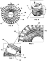
- a common fact found on machines of this type is the flux leak, caused by the magnetic short-circuit of the magnets through the steel bridges formed at the following points: 1) between the grooves for allocation of the magnets of a same pole; 2) between the grooves for allocation of the magnets and the adjacent grooves of the cage/ 3) between the beak of the rotor grooves and the outer diameter of the rotor.
- This effect, as well as the flux-loss points can be better understood from figure 6 , which shows the magnetic flux lines.
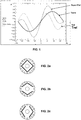
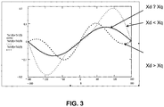
- the total torque generated by the motor in synchronous speed is the sum of Tsync + Trel. In this way, one can observe that the direct-axis reluctance and quadrature-axis reluctance have a great influence on the maximum torque value obtained.
- the Xd and Xq values were obtained by analysis of finite elements.
- equations 1 and 2 one calculates the value of the total torque as a function of the motor load angle, as shown in the graph of figure 3 .
- the maximum torque is greater for the case in which Xd ⁇ Xq.
- Most of the gain is due to the drop in direct-axis synchronous reactance, which increases significantly the value of the loss of the part of synchronous torque.
- Patent of Invention N° US 5,097,166 A which describes a high-speed rotor for an AC permanent magnet synchronous motor includes a stack of magnetically permeable rotor laminations.
- Each rotor lamination comprises a plurality of conductive bar slots for holding a starter winding and having openings facing outside for minimizing the flux leakage from the rotation magnetic field produced by primary windings on the stator, and magnet slots for holding permanent magnets to produce an even number of magnetic poles on the periphery of the rotor.
- the lamination further includes a plurality of flux barrier slots connected to the magnet slots for minimizing the flux leakage from the permanent magnets and forming bridges in a ring configuration between the conductive bar slots and the barrier slots.
- Patent Application N° US 2004/169431 A1 which reveals a synchronous motor including a stator, a rotor and permanent magnets.
- the rotor includes a rotor iron core and rotatable relative to the stator, a plurality of conductor bars accommodated within corresponding slots in the rotor iron core.
- the conductor bars have their opposite ends shortcircuited by respective shortcircuit rings to form a starter cage conductor.
- the rotor also has a plurality of magnet retaining slots defined therein at a location on an inner side of the conductor bars, in which hole permanent magnets are embedded.
- Patent of Invention N° US 5,818,139 A teaches permanent magnet housing spaces 3b and spaces 3c for flux barrier are formed within a rotor 3.
- a minimum value of a distance from a portion on a boundary face of the permanent magnet housing space in a rotor surface side which portion corresponds to an edge section of a permanent magnet 4 in its width direction to boundary faces of the both spaces in a rotation shaft side of the rotor 3 is determined to be greater than a distance of the permanent magnet housing space 3b in the thickness direction at an edge section of the permanent magnet 4 in its width direction, so that initial performance is maintained by preventing demagnetization of the permanent magnet due to a negative magnetic field from occurring.
- a decrease in the cost of a brushless DC motor is realized by decreasing the volume of the permanent magnet.
- the present invention has the objective of reducing the short-circuit flux close to the ends of the magnets, as well as around the cage-rotor groove, by using grooves in the rotor specifically sized for raising the reluctance to the passage of short-circuit magnetic flux and thus reduce the losses that occur according to the previous techniques.
- dynamics problems collision of the rotor
- the first free end is positioned adjacent one of the groves of the rotor cage, and the elongated bridge is formed between the free end of the fixation groove and the internal end of the cage groove.
- the elongated end is configured from an opening in the rotor and extends along the rotor and along the fixation groove.
- Such a configuration can be achieved by stamping during the manufacture of the blades that form the rotor nucleus, or still by perforation when the rotor is already mounted.
- the magnetic flux that tends to leak at the end portions of the magnet is reduced, since with the opening of the channel within the nucleus the reluctance to the short-circuit magnetic flux of the magnets is raised and the losses are minimized.
- Another solution of the present invention is to maintain the magnets within the rotor separated from each other and also to provide a reluctance-increase channel close to the other end of the magnet-fixation channel (or close to the second free end).
- the reluctance-increase channel should be configured so that it will, at the same time: (i) prevent short-circuit of the magnetic flux and (ii) maintain the strength of the rotor at levels sufficient for the characteristics of the electric machine not to be impaired when the rotor is moved.
- a surface bridge configured through an opening of the nucleus close to the surface portion and the bottom end of the cage groove (or beak of groove), such a bridge extending along the rotor surface.
- Another objective of the present invention is to generate on the rotor a significant difference in direct-axis reluctance and quadrature-axis reluctance. This is achieved by taking advantage of the grooves for arranging the magnets and elongated bridges that form reluctance-increase channels, which are arranged so as to make the passage of flux towards the direct axis difficult and to facilitate it in the direction of the quadrature axis. With this solution, it is possible to take advantage of the reluctance torque generated so as to maximize the maximum torque working condition.
- the synchronous machine according to the teachings of the present invention comprises a stator (not shown) and a rotor 10.
- the rotor 10 is substantially cylindrical in shape and has a surface portion 14 and a rotor nucleus 12, the rotor 10 being provided with grooves 15 provided on the surface portion of the rotor 14, where a cage 17 is allocated, said cage 17 being formed by conductive windings or bars 16 allocated in the grooves 15 and rings 18 that interconnect the bars at their ends.
- the assembly may receive a finish 71, as can be seen from figure 10 .
- the rotor 10 further comprises at least one pair of permanent magnets 22, which are allocated on magnet-fixation grooves 20, these magnet-fixation grooves 20 being positioned longitudinally on the rotor 10 nucleus.
- the magnet-fixation groove 20 extends along the rotor 10 and has a substantially rectangular section having an engagement region R E and a first free-end portion 25 and a second free-end portion 26.
- each permanent magnet 22 is fixed associated to the rotor 10 in the engagement region R E .
- the rotor 10 has poles that extend along a number of cage grooves 16, so that for the sake of explanation in the 2-pole configuration one can divide each pole as having a central pole region C P and two end pole regions E P .
- the magnet-fixation grooves 20 are positioned in a secant manner with respect to the surface portion 14 of the rotor 10 and extend between one of the end pole regions E P and the central pole region C P , the fixation grooves coming close to the groove bottom (or beak) 15' of the cage grooves 16.
- the fixation groove 22 has a reluctance-increase channel 50 near the first free end 25, the reluctance-increase channel 50 being configured so as to form an elongate bridge, built so as to accompany the whole or at least most of the groove bottom 15' of adjacent rotor.
- This configuration can be seen in greater detail in figure 7 .
- the magnet-fixation grooves 20 are position positioned in "V" and are arranged in pairs, each groove of the pair being positioned symmetrically, extending from the end pole regions E P to the central pole region C P , the fixation groove pair 20 coming close to and adjacent the central pole region C P and the respective second end portions 26 remaining adjacent each other.
- the magnet-fixation groove is configured so as to form a second elongate end 102 forming the reluctance-increase channel 60 extending from the respective second free-end portion 26 towards the second free-end portion 26 of the other fixation groove 20 of the pair, so that this channel will be adjacent the central pole region C P .
- each of the permanent magnets 22 has a rectangular cross section having first and second terminations, and between the pair of fixation grooves 20 the second elongate end forming the reluctance-increase channel 60 is configured so as to extend in the radial direction with respect to the geometrical center of the rotor 10, in the direction of a direct axis, so as to form a second elongate end 102 forming a rotor 10 nucleus 12 fillet with an extension 24 in the radial direction that is substantially greater than in the region of the reluctance-increase channel 60 with respect to a width 23 of the magnet-fixation groove 20.
- the reluctance-increase channel which may be configures so as to have parallel (see reference number 60) or non-parallel (see reference number 80) side edges, both configuration being made so as to meet simultaneously the motor performance restrictions, as well as the respective strength of the rotor 10.
- one opts for extending the second elongate ends 102 located in the central pole region C P so that they will be positioned adjacent the other elongate end of the pair and positioned very close to each other.
- these cage grooves 16 are built so as to have a surface bridge 70 configured through an opening of the nucleus 12, this surface bridge 70 being provided between the surface portion 14 of the rotor 10 and the outer end of the outer end of the cage groove 16 and extending along the surface portion 14 of the rotor 10.
- each fixation groove 20 extends between an end pole region E P to another subsequent end pole region E P , forming a third elongate end 103, which is configured so that the reluctance-increase channel 50 can be configured close to the groove bottom 15', surrounding it parallel to the respective profile, in the same way as in the first embodiment of the present application, that is to say, close to the first free end 25.
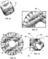
- the angle between the fixation grooves 20 is of 90°, one can opt for configuring the inner region of the ends of the fixation grooves 100, so that it will have parallel side edges 60' as can be seen in detail from figure 13 , or non-parallel (not shown), as shown in figure 11 that illustrates the other embodiment.
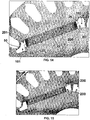
- FIGS 14 and 15 show alternatives for the shape of the ends of the fixation grooves, which can be used for the purpose of facilitating the manufacture process and preventing the displacement of the magnet 22 during magnetization and/or normal functioning of the machine, the basic principle of these alternative shapes being the use of displacement limiters 200, 201 adjacent the end portions 25, 26 of the magnet, the limiters being formed by nucleus 12 portions that extend inside the magnet-fixation groove 20 in a direction parallel to the magnet thickness, forming protrusions that limits its displacement to the sides.
- one can opt for the configuration illustrated in figure 14 where only one of the sides of the groove has displacement limiters 200, 201. At each end one may opt for design the limiter coming from one side opposite the groove, or may configure the limiters whenever the came from one side of the groove, or still provided only at one end portions, as can be seen from the configuration illustrated in figure 15 .
- the other characteristics of the synchronous machine remain unchanged.
- one provides a process of manufacturing a synchronous machine, which has two stamping steps to form the reluctance-increase channels 50 and 60 near the magnet-fixation grooves, as well as comprises a stamping step for making an opening 70 of the nucleus 12 between the surface portion and the outer end of a cage groove.
- the gains of the present invention are significant.
- the use of the elongate bridges and of the elongate ands guarantees greater utilization of the flux generated.
- a motor built according to the teachings of the prior art has flux utilization ranging from 80 to 85%, whereas with a motor built according to the teachings of the present invention the performance ranges from 85 to 90%.
Landscapes
- Engineering & Computer Science (AREA)
- Power Engineering (AREA)
- Permanent Field Magnets Of Synchronous Machinery (AREA)
- Iron Core Of Rotating Electric Machines (AREA)
- Permanent Magnet Type Synchronous Machine (AREA)
- Manufacture Of Motors, Generators (AREA)
Applications Claiming Priority (2)
| Application Number | Priority Date | Filing Date | Title |
|---|---|---|---|
| BRPI0603363-6A BRPI0603363B1 (pt) | 2006-08-16 | 2006-08-16 | "máquina síncrona" |
| PCT/BR2007/000206 WO2008019459A1 (en) | 2006-08-16 | 2007-08-15 | A synchronous machine and a process of manufacturing a synchronous machine |
Publications (2)
| Publication Number | Publication Date |
|---|---|
| EP2059989A1 EP2059989A1 (en) | 2009-05-20 |
| EP2059989B1 true EP2059989B1 (en) | 2018-01-10 |
Family
ID=38694620
Family Applications (1)
| Application Number | Title | Priority Date | Filing Date |
|---|---|---|---|
| EP07784935.4A Not-in-force EP2059989B1 (en) | 2006-08-16 | 2007-08-15 | A synchronous machine and a process of manufacturing a synchronous machine |
Country Status (8)
Families Citing this family (16)
| Publication number | Priority date | Publication date | Assignee | Title |
|---|---|---|---|---|
| JP5433198B2 (ja) | 2008-10-16 | 2014-03-05 | 日立オートモティブシステムズ株式会社 | 回転電機及び電気自動車 |
| BRPI0900907A2 (pt) * | 2009-03-31 | 2010-12-14 | Whirlpool Sa | motor sÍncrono e de induÇço |
| FI20115076A0 (fi) * | 2011-01-26 | 2011-01-26 | Axco Motors Oy | Kestomagneettitahtikoneen laminoitu roottorirakenne |
| JP5404684B2 (ja) * | 2011-03-29 | 2014-02-05 | 三菱電機株式会社 | 埋め込み磁石型モータ |
| EP2509198B1 (en) * | 2011-04-08 | 2016-04-06 | Grundfos Management A/S | Rotor |
| WO2013077109A1 (ja) * | 2011-11-25 | 2013-05-30 | 日産自動車株式会社 | 電動機 |
| US9705388B2 (en) * | 2011-12-19 | 2017-07-11 | Baldor Electric Company | Rotor for a line start permanent magnet machine |
| US20140283373A1 (en) * | 2011-12-19 | 2014-09-25 | Baldor Electric Company | Lamination for a Permanent Magnet Machine |
| US20140285050A1 (en) * | 2011-12-19 | 2014-09-25 | Baldor Electric Company | Asymmetric Rotor for a Line Start Permanent Magnet Machine |
| CN102957286A (zh) * | 2012-11-07 | 2013-03-06 | 温岭市东菱电机有限公司 | 纺织机用的永磁同步电机 |
| JP2014212599A (ja) * | 2013-04-17 | 2014-11-13 | 日本電産テクノモータ株式会社 | 誘導同期電動機 |
| CN103607061A (zh) * | 2013-12-03 | 2014-02-26 | 山东省科学院自动化研究所 | 直轴电感大于交轴电感的永磁电机转子 |
| CN104104168B (zh) * | 2014-07-16 | 2016-08-24 | 东南大学 | 一种内置永磁式无刷直流电机的定子转子结构 |
| PL242450B1 (pl) * | 2021-01-27 | 2023-02-20 | Politechnika Wroclawska | Wirnik silnika synchronicznego z magnesami trwałymi |
| CN114640226B (zh) * | 2022-03-09 | 2024-03-26 | 上海电机系统节能工程技术研究中心有限公司 | 二极电机转子冲片设计方法 |
| JP2024005784A (ja) * | 2022-06-30 | 2024-01-17 | 東芝インフラシステムズ株式会社 | 回転子およびその回転子を備えたモータ |
Family Cites Families (15)
| Publication number | Priority date | Publication date | Assignee | Title |
|---|---|---|---|---|
| US4139790A (en) * | 1977-08-31 | 1979-02-13 | Reliance Electric Company | Direct axis aiding permanent magnets for a laminated synchronous motor rotor |
| US4358697A (en) * | 1981-08-19 | 1982-11-09 | Siemens-Allis, Inc. | Two-pole permanent magnet synchronous motor rotor |
| US4570333A (en) * | 1983-10-28 | 1986-02-18 | General Electric Company | Method of making a permanent magnet rotor |
| US4922152A (en) * | 1988-07-27 | 1990-05-01 | Siemens Energy & Automation, Inc. | Synchronous machine rotor lamination |
| US5097166A (en) * | 1990-09-24 | 1992-03-17 | Reuland Electric | Rotor lamination for an AC permanent magnet synchronous motor |
| WO1996003793A1 (fr) * | 1994-07-25 | 1996-02-08 | Daikin Industries, Ltd. | Moteur a courant continu sans balais |
| JP4090630B2 (ja) * | 1999-07-16 | 2008-05-28 | 松下電器産業株式会社 | 自己始動形永久磁石式同期電動機 |
| DE60023704T2 (de) * | 1999-07-16 | 2006-08-03 | Matsushita Electric Industrial Co., Ltd., Kadoma | Synchronmotor mit dauermagneten |
| US6891299B2 (en) * | 2000-05-03 | 2005-05-10 | Moteurs Leroy-Somer | Rotary electric machine having a flux-concentrating rotor and a stator with windings on teeth |
| JP4363746B2 (ja) * | 2000-05-25 | 2009-11-11 | 株式会社東芝 | 永久磁石式リラクタンス型回転電機 |
| JP2003088020A (ja) * | 2001-09-13 | 2003-03-20 | Techno Takatsuki Co Ltd | 籠形回転子およびその製法、ならびに該籠形回転子を用いる誘導同期電動機 |
| JP2004274826A (ja) * | 2003-03-06 | 2004-09-30 | Fuji Electric Systems Co Ltd | 回転子ブロックおよび回転子 |
| JP4029817B2 (ja) * | 2003-10-10 | 2008-01-09 | 日産自動車株式会社 | 回転電機の磁気回路構造 |
| KR100565220B1 (ko) * | 2003-10-14 | 2006-03-30 | 엘지전자 주식회사 | 자기저항 동기 전동기 |
| DE102005060118A1 (de) * | 2004-12-20 | 2006-07-06 | Danfoss Compressors Gmbh | Rotor für einen elektrischen Motor |
-
2006
- 2006-08-16 BR BRPI0603363-6A patent/BRPI0603363B1/pt not_active IP Right Cessation
-
2007
- 2007-08-15 ES ES07784935.4T patent/ES2663573T3/es active Active
- 2007-08-15 EP EP07784935.4A patent/EP2059989B1/en not_active Not-in-force
- 2007-08-15 WO PCT/BR2007/000206 patent/WO2008019459A1/en active Application Filing
- 2007-08-15 KR KR1020097005311A patent/KR101431291B1/ko not_active Expired - Fee Related
- 2007-08-15 JP JP2009524050A patent/JP5270548B2/ja not_active Expired - Fee Related
- 2007-08-15 CN CN200780038404.8A patent/CN101529694B/zh not_active Expired - Fee Related
-
2009
- 2009-02-17 US US12/372,427 patent/US7923882B2/en not_active Expired - Fee Related
Also Published As
| Publication number | Publication date |
|---|---|
| BRPI0603363B1 (pt) | 2018-03-13 |
| JP2010500857A (ja) | 2010-01-07 |
| US20100156228A1 (en) | 2010-06-24 |
| ES2663573T3 (es) | 2018-04-13 |
| JP5270548B2 (ja) | 2013-08-21 |
| WO2008019459A1 (en) | 2008-02-21 |
| EP2059989A1 (en) | 2009-05-20 |
| KR101431291B1 (ko) | 2014-08-20 |
| CN101529694B (zh) | 2015-06-17 |
| CN101529694A (zh) | 2009-09-09 |
| KR20090048631A (ko) | 2009-05-14 |
| BRPI0603363A (pt) | 2008-04-08 |
| US7923882B2 (en) | 2011-04-12 |
Similar Documents
| Publication | Publication Date | Title |
|---|---|---|
| EP2059989B1 (en) | A synchronous machine and a process of manufacturing a synchronous machine | |
| US7923881B2 (en) | Interior permanent magnet motor and rotor | |
| EP2840692B1 (en) | Spoke permanent magnet machine with reduced torque ripple and method of manufacturing thereof | |
| EP1641103B1 (en) | A motor using a rotor including interior permanent magnets | |
| EP1813010B1 (en) | Design of the magnet and webs in interior permanent magent rotors | |
| US20100219712A1 (en) | Rotor of rotary electric machine, and production method therefor | |
| CN102044944B (zh) | 永磁铁式旋转电机 | |
| KR101904922B1 (ko) | 라인기동식 동기형 릴럭턴스 전동기 및 그 회전자 | |
| JP5565170B2 (ja) | 永久磁石式回転機 | |
| US20080296990A1 (en) | Arrangement of Rotor Laminations of a Permanently Excited Electrical Machine | |
| EP3506462B1 (en) | Rotary electric machine | |
| EP2410639B1 (en) | High power-density, high efficiency, non-permanent magnet electric machine | |
| JP2000197325A (ja) | リラクタンスモ―タ | |
| CN114556749B (zh) | 转子及电动机 | |
| EP1713163A1 (en) | Ipm rotating electric machine | |
| EP3823136A1 (en) | Rotor for a synchronous machine | |
| EP4047788A1 (en) | Rotary electric machine | |
| CN108141069B (zh) | 用于旋转电机的转子 | |
| JP4396142B2 (ja) | 永久磁石回転電機 | |
| KR101106420B1 (ko) | 로터 및 동기 릴럭턴스 모터 | |
| JP2024007285A (ja) | 埋込磁石型回転子および回転電機 | |
| JP3072504B2 (ja) | 電動機の回転子 | |
| WO2022176829A1 (ja) | ロータ | |
| JP2011083114A (ja) | 電動機 | |
| JP2011036071A (ja) | 電動機 |
Legal Events
| Date | Code | Title | Description |
|---|---|---|---|
| PUAI | Public reference made under article 153(3) epc to a published international application that has entered the european phase |
Free format text: ORIGINAL CODE: 0009012 |
|
| 17P | Request for examination filed |
Effective date: 20090313 |
|
| AK | Designated contracting states |
Kind code of ref document: A1 Designated state(s): AT BE BG CH CY CZ DE DK EE ES FI FR GB GR HU IE IS IT LI LT LU LV MC MT NL PL PT RO SE SI SK TR |
|
| AX | Request for extension of the european patent |
Extension state: AL BA HR MK RS |
|
| DAX | Request for extension of the european patent (deleted) | ||
| RAP1 | Party data changed (applicant data changed or rights of an application transferred) |
Owner name: WHIRLPOOL S.A. |
|
| STAA | Information on the status of an ep patent application or granted ep patent |
Free format text: STATUS: EXAMINATION IS IN PROGRESS |
|
| 17Q | First examination report despatched |
Effective date: 20161123 |
|
| GRAP | Despatch of communication of intention to grant a patent |
Free format text: ORIGINAL CODE: EPIDOSNIGR1 |
|
| STAA | Information on the status of an ep patent application or granted ep patent |
Free format text: STATUS: GRANT OF PATENT IS INTENDED |
|
| INTG | Intention to grant announced |
Effective date: 20170731 |
|
| GRAS | Grant fee paid |
Free format text: ORIGINAL CODE: EPIDOSNIGR3 |
|
| GRAA | (expected) grant |
Free format text: ORIGINAL CODE: 0009210 |
|
| STAA | Information on the status of an ep patent application or granted ep patent |
Free format text: STATUS: THE PATENT HAS BEEN GRANTED |
|
| AK | Designated contracting states |
Kind code of ref document: B1 Designated state(s): AT BE BG CH CY CZ DE DK EE ES FI FR GB GR HU IE IS IT LI LT LU LV MC MT NL PL PT RO SE SI SK TR |
|
| REG | Reference to a national code |
Ref country code: GB Ref legal event code: FG4D |
|
| REG | Reference to a national code |
Ref country code: CH Ref legal event code: EP Ref country code: AT Ref legal event code: REF Ref document number: 963453 Country of ref document: AT Kind code of ref document: T Effective date: 20180115 |
|
| REG | Reference to a national code |
Ref country code: IE Ref legal event code: FG4D |
|
| REG | Reference to a national code |
Ref country code: DE Ref legal event code: R096 Ref document number: 602007053668 Country of ref document: DE |
|
| REG | Reference to a national code |
Ref country code: ES Ref legal event code: FG2A Ref document number: 2663573 Country of ref document: ES Kind code of ref document: T3 Effective date: 20180413 |
|
| REG | Reference to a national code |
Ref country code: NL Ref legal event code: MP Effective date: 20180110 |
|
| REG | Reference to a national code |
Ref country code: SK Ref legal event code: T3 Ref document number: E 26714 Country of ref document: SK |
|
| REG | Reference to a national code |
Ref country code: AT Ref legal event code: MK05 Ref document number: 963453 Country of ref document: AT Kind code of ref document: T Effective date: 20180110 |
|
| PG25 | Lapsed in a contracting state [announced via postgrant information from national office to epo] |
Ref country code: NL Free format text: LAPSE BECAUSE OF FAILURE TO SUBMIT A TRANSLATION OF THE DESCRIPTION OR TO PAY THE FEE WITHIN THE PRESCRIBED TIME-LIMIT Effective date: 20180110 |
|
| PG25 | Lapsed in a contracting state [announced via postgrant information from national office to epo] |
Ref country code: LT Free format text: LAPSE BECAUSE OF FAILURE TO SUBMIT A TRANSLATION OF THE DESCRIPTION OR TO PAY THE FEE WITHIN THE PRESCRIBED TIME-LIMIT Effective date: 20180110 Ref country code: CY Free format text: LAPSE BECAUSE OF FAILURE TO SUBMIT A TRANSLATION OF THE DESCRIPTION OR TO PAY THE FEE WITHIN THE PRESCRIBED TIME-LIMIT Effective date: 20180110 Ref country code: FI Free format text: LAPSE BECAUSE OF FAILURE TO SUBMIT A TRANSLATION OF THE DESCRIPTION OR TO PAY THE FEE WITHIN THE PRESCRIBED TIME-LIMIT Effective date: 20180110 |
|
| PG25 | Lapsed in a contracting state [announced via postgrant information from national office to epo] |
Ref country code: LV Free format text: LAPSE BECAUSE OF FAILURE TO SUBMIT A TRANSLATION OF THE DESCRIPTION OR TO PAY THE FEE WITHIN THE PRESCRIBED TIME-LIMIT Effective date: 20180110 Ref country code: SE Free format text: LAPSE BECAUSE OF FAILURE TO SUBMIT A TRANSLATION OF THE DESCRIPTION OR TO PAY THE FEE WITHIN THE PRESCRIBED TIME-LIMIT Effective date: 20180110 Ref country code: PL Free format text: LAPSE BECAUSE OF FAILURE TO SUBMIT A TRANSLATION OF THE DESCRIPTION OR TO PAY THE FEE WITHIN THE PRESCRIBED TIME-LIMIT Effective date: 20180110 Ref country code: IS Free format text: LAPSE BECAUSE OF FAILURE TO SUBMIT A TRANSLATION OF THE DESCRIPTION OR TO PAY THE FEE WITHIN THE PRESCRIBED TIME-LIMIT Effective date: 20180510 Ref country code: AT Free format text: LAPSE BECAUSE OF FAILURE TO SUBMIT A TRANSLATION OF THE DESCRIPTION OR TO PAY THE FEE WITHIN THE PRESCRIBED TIME-LIMIT Effective date: 20180110 Ref country code: BG Free format text: LAPSE BECAUSE OF FAILURE TO SUBMIT A TRANSLATION OF THE DESCRIPTION OR TO PAY THE FEE WITHIN THE PRESCRIBED TIME-LIMIT Effective date: 20180410 |
|
| REG | Reference to a national code |
Ref country code: DE Ref legal event code: R097 Ref document number: 602007053668 Country of ref document: DE |
|
| PG25 | Lapsed in a contracting state [announced via postgrant information from national office to epo] |
Ref country code: EE Free format text: LAPSE BECAUSE OF FAILURE TO SUBMIT A TRANSLATION OF THE DESCRIPTION OR TO PAY THE FEE WITHIN THE PRESCRIBED TIME-LIMIT Effective date: 20180110 Ref country code: RO Free format text: LAPSE BECAUSE OF FAILURE TO SUBMIT A TRANSLATION OF THE DESCRIPTION OR TO PAY THE FEE WITHIN THE PRESCRIBED TIME-LIMIT Effective date: 20180110 |
|
| PLBE | No opposition filed within time limit |
Free format text: ORIGINAL CODE: 0009261 |
|
| STAA | Information on the status of an ep patent application or granted ep patent |
Free format text: STATUS: NO OPPOSITION FILED WITHIN TIME LIMIT |
|
| PG25 | Lapsed in a contracting state [announced via postgrant information from national office to epo] |
Ref country code: DK Free format text: LAPSE BECAUSE OF FAILURE TO SUBMIT A TRANSLATION OF THE DESCRIPTION OR TO PAY THE FEE WITHIN THE PRESCRIBED TIME-LIMIT Effective date: 20180110 Ref country code: CZ Free format text: LAPSE BECAUSE OF FAILURE TO SUBMIT A TRANSLATION OF THE DESCRIPTION OR TO PAY THE FEE WITHIN THE PRESCRIBED TIME-LIMIT Effective date: 20180110 |
|
| 26N | No opposition filed |
Effective date: 20181011 |
|
| PG25 | Lapsed in a contracting state [announced via postgrant information from national office to epo] |
Ref country code: SI Free format text: LAPSE BECAUSE OF FAILURE TO SUBMIT A TRANSLATION OF THE DESCRIPTION OR TO PAY THE FEE WITHIN THE PRESCRIBED TIME-LIMIT Effective date: 20180110 |
|
| REG | Reference to a national code |
Ref country code: ES Ref legal event code: PC2A Owner name: EMBRACO INDUSTRIA DE COMPRESSORES E SOLUSOES EM RE Effective date: 20190227 |
|
| REG | Reference to a national code |
Ref country code: DE Ref legal event code: R082 Ref document number: 602007053668 Country of ref document: DE Representative=s name: PFENNING, MEINIG & PARTNER MBB PATENTANWAELTE, DE Ref country code: DE Ref legal event code: R081 Ref document number: 602007053668 Country of ref document: DE Owner name: EMBRACO INDUSTRIA DE COMPRESSORES E SOLUCOES E, BR Free format text: FORMER OWNER: WHIRLPOOL S.A., SAO PAULO, BR Ref country code: DE Ref legal event code: R082 Ref document number: 602007053668 Country of ref document: DE Representative=s name: SCHIEBER FARAGO PATENTANWAELTE, DE |
|
| PG25 | Lapsed in a contracting state [announced via postgrant information from national office to epo] |
Ref country code: MC Free format text: LAPSE BECAUSE OF FAILURE TO SUBMIT A TRANSLATION OF THE DESCRIPTION OR TO PAY THE FEE WITHIN THE PRESCRIBED TIME-LIMIT Effective date: 20180110 |
|
| REG | Reference to a national code |
Ref country code: CH Ref legal event code: PL |
|
| GBPC | Gb: european patent ceased through non-payment of renewal fee |
Effective date: 20180815 |
|
| PG25 | Lapsed in a contracting state [announced via postgrant information from national office to epo] |
Ref country code: CH Free format text: LAPSE BECAUSE OF NON-PAYMENT OF DUE FEES Effective date: 20180831 Ref country code: LU Free format text: LAPSE BECAUSE OF NON-PAYMENT OF DUE FEES Effective date: 20180815 Ref country code: LI Free format text: LAPSE BECAUSE OF NON-PAYMENT OF DUE FEES Effective date: 20180831 |
|
| REG | Reference to a national code |
Ref country code: BE Ref legal event code: MM Effective date: 20180831 |
|
| REG | Reference to a national code |
Ref country code: IE Ref legal event code: MM4A |
|
| REG | Reference to a national code |
Ref country code: SK Ref legal event code: PC4A Ref document number: E 26714 Country of ref document: SK Owner name: EMBRACO INDUSTRIA DE COMPRESSORES E SOLUCOES E, BR Free format text: FORMER OWNER: WHIRLPOOL S.A., SAO PAULO SP, BR Effective date: 20190503 |
|
| PG25 | Lapsed in a contracting state [announced via postgrant information from national office to epo] |
Ref country code: IE Free format text: LAPSE BECAUSE OF NON-PAYMENT OF DUE FEES Effective date: 20180815 |
|
| PG25 | Lapsed in a contracting state [announced via postgrant information from national office to epo] |
Ref country code: FR Free format text: LAPSE BECAUSE OF NON-PAYMENT OF DUE FEES Effective date: 20180831 Ref country code: BE Free format text: LAPSE BECAUSE OF NON-PAYMENT OF DUE FEES Effective date: 20180831 |
|
| PG25 | Lapsed in a contracting state [announced via postgrant information from national office to epo] |
Ref country code: GB Free format text: LAPSE BECAUSE OF NON-PAYMENT OF DUE FEES Effective date: 20180815 |
|
| PGFP | Annual fee paid to national office [announced via postgrant information from national office to epo] |
Ref country code: TR Payment date: 20190731 Year of fee payment: 13 |
|
| PG25 | Lapsed in a contracting state [announced via postgrant information from national office to epo] |
Ref country code: MT Free format text: LAPSE BECAUSE OF NON-PAYMENT OF DUE FEES Effective date: 20180815 |
|
| PG25 | Lapsed in a contracting state [announced via postgrant information from national office to epo] |
Ref country code: PT Free format text: LAPSE BECAUSE OF FAILURE TO SUBMIT A TRANSLATION OF THE DESCRIPTION OR TO PAY THE FEE WITHIN THE PRESCRIBED TIME-LIMIT Effective date: 20180110 Ref country code: HU Free format text: LAPSE BECAUSE OF FAILURE TO SUBMIT A TRANSLATION OF THE DESCRIPTION OR TO PAY THE FEE WITHIN THE PRESCRIBED TIME-LIMIT; INVALID AB INITIO Effective date: 20070815 |
|
| PG25 | Lapsed in a contracting state [announced via postgrant information from national office to epo] |
Ref country code: GR Free format text: LAPSE BECAUSE OF FAILURE TO SUBMIT A TRANSLATION OF THE DESCRIPTION OR TO PAY THE FEE WITHIN THE PRESCRIBED TIME-LIMIT Effective date: 20180110 |
|
| REG | Reference to a national code |
Ref country code: DE Ref legal event code: R082 Ref document number: 602007053668 Country of ref document: DE Representative=s name: SCHIEBER FARAGO PATENTANWAELTE, DE |
|
| PGFP | Annual fee paid to national office [announced via postgrant information from national office to epo] |
Ref country code: IT Payment date: 20210129 Year of fee payment: 14 |
|
| PGFP | Annual fee paid to national office [announced via postgrant information from national office to epo] |
Ref country code: DE Payment date: 20210129 Year of fee payment: 14 Ref country code: ES Payment date: 20210326 Year of fee payment: 14 |
|
| PGFP | Annual fee paid to national office [announced via postgrant information from national office to epo] |
Ref country code: SK Payment date: 20210211 Year of fee payment: 14 |
|
| REG | Reference to a national code |
Ref country code: DE Ref legal event code: R119 Ref document number: 602007053668 Country of ref document: DE |
|
| REG | Reference to a national code |
Ref country code: SK Ref legal event code: MM4A Ref document number: E 26714 Country of ref document: SK Effective date: 20210815 |
|
| PG25 | Lapsed in a contracting state [announced via postgrant information from national office to epo] |
Ref country code: TR Free format text: LAPSE BECAUSE OF NON-PAYMENT OF DUE FEES Effective date: 20200815 |
|
| PG25 | Lapsed in a contracting state [announced via postgrant information from national office to epo] |
Ref country code: SK Free format text: LAPSE BECAUSE OF NON-PAYMENT OF DUE FEES Effective date: 20210815 Ref country code: IT Free format text: LAPSE BECAUSE OF NON-PAYMENT OF DUE FEES Effective date: 20210815 Ref country code: DE Free format text: LAPSE BECAUSE OF NON-PAYMENT OF DUE FEES Effective date: 20220301 |
|
| REG | Reference to a national code |
Ref country code: ES Ref legal event code: FD2A Effective date: 20220930 |
|
| PG25 | Lapsed in a contracting state [announced via postgrant information from national office to epo] |
Ref country code: ES Free format text: LAPSE BECAUSE OF NON-PAYMENT OF DUE FEES Effective date: 20210816 |