EP1641103B1 - A motor using a rotor including interior permanent magnets - Google Patents
A motor using a rotor including interior permanent magnets Download PDFInfo
- Publication number
- EP1641103B1 EP1641103B1 EP05025811A EP05025811A EP1641103B1 EP 1641103 B1 EP1641103 B1 EP 1641103B1 EP 05025811 A EP05025811 A EP 05025811A EP 05025811 A EP05025811 A EP 05025811A EP 1641103 B1 EP1641103 B1 EP 1641103B1
- Authority
- EP
- European Patent Office
- Prior art keywords
- rotor
- grooves
- magnets
- slits
- rotor core
- Prior art date
- Legal status (The legal status is an assumption and is not a legal conclusion. Google has not performed a legal analysis and makes no representation as to the accuracy of the status listed.)
- Expired - Lifetime
Links
Images


Classifications
-
- H—ELECTRICITY
- H02—GENERATION; CONVERSION OR DISTRIBUTION OF ELECTRIC POWER
- H02K—DYNAMO-ELECTRIC MACHINES
- H02K1/00—Details of the magnetic circuit
- H02K1/06—Details of the magnetic circuit characterised by the shape, form or construction
- H02K1/22—Rotating parts of the magnetic circuit
- H02K1/27—Rotor cores with permanent magnets
- H02K1/2706—Inner rotors
- H02K1/272—Inner rotors the magnetisation axis of the magnets being perpendicular to the rotor axis
- H02K1/274—Inner rotors the magnetisation axis of the magnets being perpendicular to the rotor axis the rotor consisting of two or more circumferentially positioned magnets
- H02K1/2753—Inner rotors the magnetisation axis of the magnets being perpendicular to the rotor axis the rotor consisting of two or more circumferentially positioned magnets the rotor consisting of magnets or groups of magnets arranged with alternating polarity
- H02K1/276—Magnets embedded in the magnetic core, e.g. interior permanent magnets [IPM]
Definitions
- the present invention relates in general to motors for actuating air conditioners, industrial machines, electric vehicles, etc., and, more particularly, the invention relates to the structure of a motor having a rotor inside which permanent magnets are set so that reluctance torque as well as magnetic torque is utilized.
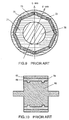
- FIG. 9 is a cross sectional view showing the rotor of such conventional motor.
- the rotor is shaped into a cylinder having substantially the same shaft as that of a stator (not illustrated) and is supported by a bearing (not illustrated) for rotating on a shaft 76.
- the rotor has eight permanent magnet slits 73 inside a rotor 71, and these slits are disposed, along the rotating direction of the rotor, at the intervals of substantially same spacing and are extended through the core along the direction of the shaft.
- an adhesive is applied, then plate shaped permanent magnets 72 are inserted, and the magnets 72 are stuck to the rotor core 71.
- the rotor has eight magnetic poles.
- the rotor is disposed inside the stator leaving a narrow annular clearance, then it is rotated by the attracting and repulsing force of the magnetic poles of the rotor to the stator teeth, which have rotating magnetic fields created by the electric current which runs through the windings of the stator.
- the rotor has the permanent magnet slits 73 in the rotor core 71, then the adhesive is applied to the walls of the slits 73, then the permanent magnets 72 are stuck inside the slits 73. Then, if the clearances between the slits 73 and the magnets 72 are large, the positions of the magnets 72 become unstable, then the magnetic flux disperses and the characteristic of the motor is deteriorated.
- the big clearances cause the use of thick layers of the adhesive, whereby the effective magnetic flux decreases, which results in a decrease in the torque.
- the magnetic resistance increases between them, so that the magnetic flux, which is produced by magnets 72 and runs into the stator, decreases, then the magnetic torque decreases and the output power of the motor also decreases.
- stabilization of the positions of the magnets 73 is tried by decreasing the clearances between the slits 73 and the magnets 72 by adjusting the section size of the magnets 72 and that of the inserting openings of the slits 73 to be substantially the same.
- the adhesive layers between the walls of the slits 73 and the magnets 72 mostly disappear, causing concern as to whether the magnets 72 are firmly stuck inside the slits or not. Also, if the adhesive layers are not thick enough, the motor may loose reliability on the problem of the dropping out of the magnets 72 at high speed rotation.
- the rotor of "the interior permanent magnet motor” is driven not only by the magnetic torque, which directly contributes for generating the torque by the magnetic flux which is produced by magnets 72 and runs into the stator, but also the motor is driven by utilizing the reluctance torque, which is generated by the above described difference between the inductance "Ld” and the inductance "Lq". While if the space of the outer rotor rim 75 between the magnets 72 and the outer rim edge of the rotor core 71 is narrow, the magnetic flux path becomes also narrow, then the magnetic saturation occurs, and the volume of the magnetic flux which runs there decreases and the reluctance torque becomes small.
- the rotor as illustrated in Fig. 10 , has a groove 84 for absorbing the excess of an adhesive 88 applied to a portion where a cylindrical permanent magnet 82 is stuck to a shaft 86.
- the thickness of the adhesive layer 88 is enlarged.
- the structure is not the one in which the permanent magnet is set inside a rotor, but it is the one in which the cylindrical permanent magnet 82 is stuck to the surface of the shaft 86 with an adhesive, that is so called “a surface permanent magnet motor”, namely that is the motor in which the permanent magnet 82 is just stuck to the shaft 86 with the adhesive.
- the Japanese patent application JP 05 236 684 A discloses a brushless DC motor comprising a stator having a plurality of teeth provided with windings, and a rotor having permanent magnets therein, wherein, the rotor comprises: a rotating shaft disposed at the center part of the rotor, a rotor core fixed to the rotating shaft, permanent magnet slits formed in the rotor core radially inwardly of the outer rim of the rotor core, and permanent magnets inserted into the permanent magnet slits.
- the present invention aims to provide "an interior permanent magnet motor” having a rotor which has permanent magnets stuck surely inside it so that the reliability is improved, and the rotor also has wide outer rotor rim space between the permanent magnets and the outer rotor rim edge for providing a wide magnetic flux path, still the travels of the magnetic flux into the adjacent magnets are suppressed, so that the efficiency is also improved.
- the present invention provides a motor according to claims 1 or 2.
- the adhesive remains at least in the grooves, so that the magnets are surely stuck to the rotor core. Also in the present invention, by forming the portions of low magnetic induction at the outer rotor rim side corners of the permanent magnet slits, the travels of the magnetic flux into the adjacent magnets are suppressed, so that the efficient motor is realized.
- the magnets are surely stuck to the rotor core and also the travels of the magnetic flux into the adjacent magnets are suppressed, which is extremely efficient.
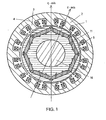
- Fig. 1 is a cross sectional view showing a motor of the first example not part of the present invention.
- Fig. 2 shows a cross sectional view of a rotor of the motor of Fig. 1 .
- Fig. 3 is a partially enlarged cross sectional view of the rotor illustrated in Fig. 2 .
- a stator 1 is formed by laminating a plurality of stator cores 2 made of annular magnetic plates, and comprises a plurality of teeth 3 and a yoke 4 for connecting the roots of the teeth.
- the teeth 3 are provided with windings 5.
- the rotor is shaped into a cylinder having substantially the same shaft with the stator 1 and is disposed inside the stator leaving annular clearance.
- a rotating shaft 16 is fixed, and the rotor is supported by a bearing (not illustrated) for rotating on the shaft 16.
- the rotor has eight permanent magnet slits 13 formed inside a rotor core 11, and these slits are disposed, along the rotating direction of the rotor, at the intervals of substantially same spacing and are extended through the core along the direction of the shaft.
- plate shaped permanent magnets 12 are inserted, then eight rotor magnetic poles are created. The rotor is rotated by the attracting and the repulsing force of the magnetic poles of the rotor to the stator teeth 3 which have rotating magnetic fields created by the electric current which runs through the stator windings 5.
- the adhesive applied to the walls of the slits 13 remains at least at the grooves 14 without being pressed out by the inserted magnet 12, so that the magnets 12 are stuck to the rotor core 11 with the remaining adhesive.
- the grooves 14 are formed at the inside slit 13 wall facing inner rim of the rotor core and also at both slit 13 corners facing the outer rim of the rotor core.
- the reason why the grooves 14 are formed at the outer rotor rim side corners of the slits 13 is as follows.
- Each of the magnets 12 has different polarities between the inner core rim side and the outer rotor rim side, so that there is the possibility of the magnetic flux short circuit of magnets 12 themselves.
- the grooves 14 illustrated in Fig. 3 the magnetic flux short circuit at the ends of the magnets 12 from one side to the other side of the magnets is suppressed.
- the suppression of the short circuit at the magnet ends becomes more effective and also the travels of the magnetic flux into the adjacent magnet, namely the magnetic flux leakage is decreased.
- the effective magnetic flux which is produced by the magnets 12 and contributes for generating torque by running into the stator 1 through the outer rotor core rim, increases.
- the strength of the rotor decreases, then there is the possibility of occurrence of a problem, for instance, at high speed rotation. In that case, by filling up the grooves 14 with the adhesive, the strength increases at the grooves 14 where the stress is concentrated during rotation, then the rotor withstands the high speed rotation.
- the magnets 12 inserted into the slits 13 and the rotor core 11 be in contact as much as possible. If there is an adhesive between the magnets 12 and the outer rotor rim side walls of the slits, the distance between the magnets 12 and the stator 1 becomes longer. Also, since the adhesive is generally non-magnetic material, if there is adhesive between the magnets 12 and the outer rotor rim side walls of the slits 13, the magnetic resistance increases, so that the magnetic flux, which is produced by the magnets 12 and runs into the stator 1, decreases.
- the magnets 12 and the rotor core 11 are contacted in at least one position, the decrease of the magnetic flux is suppressed. If the magnets 12 and the outer rotor rim side walls of slits 13 are solidly contacted, it is better. Further, if the magnets 12 and whole walls of each of the slits 13 are contacted except the portions of the grooves 14, it is still better from the stand point of generating the magnetic torque.
- the effective magnetic flux volume for generating the reluctance torque is not decreased for driving the motor utilizing the reluctance torque. Also even when the grooves 14 are formed at only inner core rim side walls of the slits 13, good effect is obtained.
- the adhesive filled in each groove spreads through the groove, so that the adhesive layers are surely formed.
- Fig. 4 is a cross sectional view showing the second example not part of the present invention.
- a rotor core 21 is fixed to a rotating shaft 26, and grooves 24 are formed at the walls of permanent magnet slits 23, then at the grooves 24, adhesive layers are formed for sticking permanent magnets 22 inside the slits 23 of the rotor core 21.
- the grooves are formed at both slit 23 corners facing the outer rim of the rotor core, and also one groove and two grooves are alternately formed at each of the inner core rim side walls of the slits 23, along the rotating direction of the rotor.
- the rotor core 21 is formed as follows. A plurality of rotor core sheets made of magnetic plates are prepared, then on each of the sheets, the slits 23 and the grooves 24 are formed.
- the grooves 24 are formed at both slit 23 corners facing the outer rotor rim of the rotor core, and also one groove and two grooves are alternately formed at the inner core rim side wall of each of the slits 23 along the rotating direction of the rotor. Then the core sheets are laminated along the direction of the shaft, and each adjacent sheet is rotated by a predetermined angle so that each slit 23 agrees with each other.
- rotor core sheets are made, for instance, by pressing piece by piece. Then the sheets are laminated to the thickness unit of "P" and "Q" as shown in the illustration. Then the rotor core is formed by laminating these units, along the direction of the shaft, rotating each adjacent unit by the angle of permanent magnet disposition, namely in this exemplary embodiment 45° (360° / the number of rotor poles). Then by applying the adhesive to the grooves 24, enough adhesive layers are formed and the magnets 22 are surely stuck inside the slits 23.
- a plurality of the grooves 24 are formed at the inner core rim side walls of the slits 23.
- the grooves 24 are widely spread, so that the adhesive layers formed in the grooves 24 are evenly disposed.
- the rotor core 21 As in this example, by forming the rotor core 21 with the method of laminating, along the shaft direction, rotated magnetic plates which has the different number of grooves on at least two different side walls of each of the slits 23, the grooves can be widely disposed with ease.
- the number of the grooves formed at inner core rim side walls is not limited to one or two, namely the number can be determined according to the necessity.
- the magnets 22 are more surely stuck to the rotor core 21.
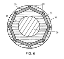
- Fig. 6 is a cross sectional view showing the third example not part of the present invention.
- a rotor is formed by laminating magnetic plates, and the rotor has a rotor core 31 fixed to a rotating shaft 36, permanent magnet slits 33 formed inside the outer rim of the rotor core 31, and plate shaped magnets 32 whose section is rectangular.
- the magnets 32 are stuck inside the slits 33 with an adhesive applied to the slits 33.
- grooves 34 of low magnetic induction are formed at both slit 33 corners facing the outer rim of the rotor core.
- the grooves 34 are extended through axially and are protruded toward the outer rotor rim side. With this structure, the distance between the outer rotor rim and the slits 33 becomes shortest at the points of the protruded grooves 34, which suppress the magnetic flux short circuit of the magnets 32 themselves at the ends of the magnets 32.
- the grooves at both rotor rim side corners of the slits 33 suppress the travels of the magnetic flux into the adjacent magnets.
- the interior permanent magnet motor which utilizes effectively reluctance torque as well as magnetic torque, is realized.
- the grooves 34 may be left empty, but it is better that these are filled up with an adhesive to increase the strength of the rotor.
- an adhesive By filling up the grooves 34 with an adhesive, the magnets 32 are stuck to the rotor core 31 with the adhesive layers in the grooves, even if the size of the slits 33 and the section size of the magnets 32 are adjusted to be substantially the same (naturally the magnets 32 are little smaller than the slits 33). Namely, when both sizes are almost same, there is possibility that the adhesive applied to the slits 33 is pressed out when the magnets 32 are inserted into the slits 33. However, by filling up the grooves 34 with the adhesive, at least the adhesive in the grooves 34 remains and the remaining adhesive surely sticks the magnets 32 to the rotor core 31.
- the grooves 34 are formed only at the corners of the slits 33. For instance, if the grooves are formed at the center part of the outer rotor rim side wall of each of the magnet slits 33, the magnetic flux is intercepted by the grooves. In addition, the magnets 32 and the walls of the slits 33 are better to be contacted as much as possible except the portions of grooves 34.
- the magnetic resistance between the magnets 32 and the outer rotor rim 35 becomes small, then the magnetic flux produced by the magnets 32 effectively runs to the outer rotor rim 35, then runs into the stator through the annular clearance between the rotor and the stator, and contributes effectively for generating the torque.
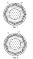
- Fig. 7 is a cross sectional view showing an exemplary embodiment of the present invention.
- the difference from the third example is that, in this exemplary embodiment, there are two types of permanent magnet slits 43 which are alternately disposed along the rotating direction of a rotor, one type has grooves 44 at both slit 43 corners facing the outer rim of the rotor core, and the other type has no groove.
- the travels of the magnetic flux into the adjacent magnets 43 are suppressed by the grooves 44, so that effective reluctance torque is obtained.
- Fig. 8 is a cross sectional view showing another exemplary embodiment of the present invention.
- the difference from the third example is that, in this exemplary embodiment, the grooves 54 are formed at one side of the outer rotor rim side corners of the permanent magnet slits 53.
- the travels of the magnetic flux into the adjacent magnets are suppressed by the groove 54 as in the third example, so that an effective reluctance torque is obtained.
- the present invention as described above, in "an interior permanent magnet motor", by forming grooves at walls of permanent magnet slits formed inside the outer rim of a rotor core, and by forming adhesive layers in the grooves for sticking the inserted magnets to the rotor core, even if the slit size and the magnet section size are substantially same, since the adhesive remains at the grooves, the magnets are surely stuck to the rotor core.
- the magnets are set at one layer.
- the same effect is obtained on motors which have magnets at more than two layers, viz., on "a multi-layer interior permanent magnet motor”. And also the same effect is obtained on the motor which has magnetic poles other than eight.
Landscapes
- Engineering & Computer Science (AREA)
- Power Engineering (AREA)
- Permanent Field Magnets Of Synchronous Machinery (AREA)
Description
- The present invention relates in general to motors for actuating air conditioners, industrial machines, electric vehicles, etc., and, more particularly, the invention relates to the structure of a motor having a rotor inside which permanent magnets are set so that reluctance torque as well as magnetic torque is utilized.
- A high efficiency motor which utilizes reluctance torque as well as magnetic torque by setting permanent magnets inside a rotor core, viz., so called "an interior permanent magnet motor" is already known.
Fig. 9 is a cross sectional view showing the rotor of such conventional motor. InFig. 9 , the rotor is shaped into a cylinder having substantially the same shaft as that of a stator (not illustrated) and is supported by a bearing (not illustrated) for rotating on ashaft 76. The rotor has eightpermanent magnet slits 73 inside arotor 71, and these slits are disposed, along the rotating direction of the rotor, at the intervals of substantially same spacing and are extended through the core along the direction of the shaft. To theslits 73, an adhesive is applied, then plate shapedpermanent magnets 72 are inserted, and themagnets 72 are stuck to therotor core 71. With this structure, the rotor has eight magnetic poles. - The rotor is disposed inside the stator leaving a narrow annular clearance, then it is rotated by the attracting and repulsing force of the magnetic poles of the rotor to the stator teeth, which have rotating magnetic fields created by the electric current which runs through the windings of the stator.
- In the above structure, the relation between the inductance "Ld" of a d-shaft direction which meets at right angles with the magnetic poles of the rotor and the inductance "Lq" of a q-shaft direction which runs through the border between adjacent rotor magnetic poles is expressed as Lq > Ld.
- Generally, the relation between a motor torque "T" and the parameters of the number of rotor magnetic pole pairs "Pn", an interlinkage flux "Ma", a stator winding current "I", an advanced phase angle (electrical angle) "b" of the current "I" to the induced voltage generated in each phase stator winding by the winding current "I" is expressed as,

- In the above described conventional structure, the rotor has the
permanent magnet slits 73 in therotor core 71, then the adhesive is applied to the walls of theslits 73, then thepermanent magnets 72 are stuck inside theslits 73. Then, if the clearances between theslits 73 and themagnets 72 are large, the positions of themagnets 72 become unstable, then the magnetic flux disperses and the characteristic of the motor is deteriorated. - In addition, the big clearances cause the use of thick layers of the adhesive, whereby the effective magnetic flux decreases, which results in a decrease in the torque. Namely, if there are thick adhesive layers between the
outer rotor rim 75 and themagnets 72, the magnetic resistance increases between them, so that the magnetic flux, which is produced bymagnets 72 and runs into the stator, decreases, then the magnetic torque decreases and the output power of the motor also decreases. - Therefore, stabilization of the positions of the
magnets 73 is tried by decreasing the clearances between theslits 73 and themagnets 72 by adjusting the section size of themagnets 72 and that of the inserting openings of theslits 73 to be substantially the same. - However, if the clearances between the walls of the
slits 73 and themagnets 72 are small, the insertion of themagnets 72 is difficult, and also the adhesive applied to the walls of theslits 73 is pressed out when themagnets 72 are inserted into theslits 73. Accordingly, the adhesive layers between the walls of theslits 73 and themagnets 72 mostly disappear, causing concern as to whether themagnets 72 are firmly stuck inside the slits or not. Also, if the adhesive layers are not thick enough, the motor may loose reliability on the problem of the dropping out of themagnets 72 at high speed rotation. - The rotor of "the interior permanent magnet motor" is driven not only by the magnetic torque, which directly contributes for generating the torque by the magnetic flux which is produced by
magnets 72 and runs into the stator, but also the motor is driven by utilizing the reluctance torque, which is generated by the above described difference between the inductance "Ld" and the inductance "Lq". While if the space of the outer rotor rim 75 between themagnets 72 and the outer rim edge of therotor core 71 is narrow, the magnetic flux path becomes also narrow, then the magnetic saturation occurs, and the volume of the magnetic flux which runs there decreases and the reluctance torque becomes small. - It has been suggested to dispose the
magnets 72 at positions closer to ashaft 76 for taking wider space of theouter rotor rim 75, and then for making a larger magnetic flux path so that the magnetic flux runs well and that the large reluctance torque is utilized. However, in that case, the ends of themagnets 72 are more separated from the outer rim edge of therotor core 71, then the magnetic flux runs into the adjacent magnets, and the effective volume of the magnetic flux for generating the torque decreases. - While, the structure for preventing the pressing out of the adhesive when permanent magnets are stuck to the rotor of a motor is stated in the
Japanese Patent Application Unexamined Publication No. H08-251850 Fig. 10 , has agroove 84 for absorbing the excess of an adhesive 88 applied to a portion where a cylindricalpermanent magnet 82 is stuck to ashaft 86. In the illustration, the thickness of theadhesive layer 88 is enlarged. - However, the structure is not the one in which the permanent magnet is set inside a rotor, but it is the one in which the cylindrical
permanent magnet 82 is stuck to the surface of theshaft 86 with an adhesive, that is so called "a surface permanent magnet motor", namely that is the motor in which thepermanent magnet 82 is just stuck to theshaft 86 with the adhesive. - The
Japanese patent application JP 05 236 684 A - The present invention aims to provide "an interior permanent magnet motor" having a rotor which has permanent magnets stuck surely inside it so that the reliability is improved, and the rotor also has wide outer rotor rim space between the permanent magnets and the outer rotor rim edge for providing a wide magnetic flux path, still the travels of the magnetic flux into the adjacent magnets are suppressed, so that the efficiency is also improved.
- Namely, the present invention provides a motor according to
claims 1 or 2. - With the structure described above, even if the size of the permanent magnet slits and the section size of the inserted permanent magnets are adjusted to be substantially same, the adhesive remains at least in the grooves, so that the magnets are surely stuck to the rotor core. Also in the present invention, by forming the portions of low magnetic induction at the outer rotor rim side corners of the permanent magnet slits, the travels of the magnetic flux into the adjacent magnets are suppressed, so that the efficient motor is realized.
- By forming the grooves at the outer rotor rim side corners of the permanent magnet slits, and by filling up the grooves with the adhesive of low magnetic induction, the magnets are surely stuck to the rotor core and also the travels of the magnetic flux into the adjacent magnets are suppressed, which is extremely efficient.
-
-
Fig. 1 is a cross sectional view showing a motor of a first exemple not part of the present invention. -
Fig. 2 is a cross sectional view showing a rotor of the first exemple. -
Fig. 3 is a partially enlarged cross sectional view of the rotor illustrated inFig. 2 . -
Fig. 4 is a cross sectional view showing a rotor of a second exemple not part of the present invention. -
Fig. 5 shows a wall of a slit for a permanent magnet of the second exemple. -
Fig. 6 is a cross sectional view showing a rotor of a third exemple not part of the present invention. -
Fig. 7 is a cross sectional view showing a rotor of an exemplary embodiment of the present invention. -
Fig. 8 is a cross sectional view showing a rotor of another exemplary embodiment of the present invention. -
Fig. 9 is a cross sectional view showing a rotor of a conventional example. -
Fig. 10 is a cross sectional view showing a rotor of a other conventional example. - In the following, explanation on the exemplary embodiments of the present invention is described referring to the attached drawings.
-
Fig. 1 is a cross sectional view showing a motor of the first exemple not part of the present invention.Fig. 2 shows a cross sectional view of a rotor of the motor ofFig. 1 .Fig. 3 is a partially enlarged cross sectional view of the rotor illustrated inFig. 2 . - In
Fig. 1 through Fig. 3 , a stator 1 is formed by laminating a plurality ofstator cores 2 made of annular magnetic plates, and comprises a plurality ofteeth 3 and ayoke 4 for connecting the roots of the teeth. Theteeth 3 are provided withwindings 5. - The rotor is shaped into a cylinder having substantially the same shaft with the stator 1 and is disposed inside the stator leaving annular clearance. At the center part of the rotor, a rotating
shaft 16 is fixed, and the rotor is supported by a bearing (not illustrated) for rotating on theshaft 16. The rotor has eightpermanent magnet slits 13 formed inside arotor core 11, and these slits are disposed, along the rotating direction of the rotor, at the intervals of substantially same spacing and are extended through the core along the direction of the shaft. Into the slits, plate shapedpermanent magnets 12 are inserted, then eight rotor magnetic poles are created. The rotor is rotated by the attracting and the repulsing force of the magnetic poles of the rotor to thestator teeth 3 which have rotating magnetic fields created by the electric current which runs through thestator windings 5. - Into the permanent magnet slits 13, rectangular
permanent magnets 12, whose section size is almost same as that of theslits 13, are inserted and are stuck inside theslits 13. At the walls of theslits 13,grooves 14 are formed, and thegrooves 14 are filled up with an adhesive made of non-magnetic material for forming adhesive layers for sticking themagnets 12 to therotor core 11. - As described above, by forming the
grooves 14 at the walls of theslits 13 in whichmagnets 12 are inserted, even if the size of theslits 13 and the section size of themagnet 12 are adjusted to be substantially same (naturally themagnets 12 are little smaller), the adhesive applied to the walls of theslits 13 remains at least at thegrooves 14 without being pressed out by the insertedmagnet 12, so that themagnets 12 are stuck to therotor core 11 with the remaining adhesive. - Referring to
Fig. 3 , the details of arotor core 11 is explained in the following. Thegrooves 14 are formed at the inside slit 13 wall facing inner rim of the rotor core and also at both slit 13 corners facing the outer rim of the rotor core. The reason why thegrooves 14 are formed at the outer rotor rim side corners of theslits 13 is as follows. - Each of the
magnets 12 has different polarities between the inner core rim side and the outer rotor rim side, so that there is the possibility of the magnetic flux short circuit ofmagnets 12 themselves. However, with thegrooves 14 illustrated inFig. 3 , the magnetic flux short circuit at the ends of themagnets 12 from one side to the other side of the magnets is suppressed. By forming the grooves protruded to the outer rotor rim side, the suppression of the short circuit at the magnet ends becomes more effective and also the travels of the magnetic flux into the adjacent magnet, namely the magnetic flux leakage is decreased. Then, the effective magnetic flux, which is produced by themagnets 12 and contributes for generating torque by running into the stator 1 through the outer rotor core rim, increases. - If the formed
grooves 14 are emptied, the strength of the rotor decreases, then there is the possibility of occurrence of a problem, for instance, at high speed rotation. In that case, by filling up thegrooves 14 with the adhesive, the strength increases at thegrooves 14 where the stress is concentrated during rotation, then the rotor withstands the high speed rotation. - It is also better for the
magnets 12 inserted into theslits 13 and therotor core 11 be in contact as much as possible. If there is an adhesive between themagnets 12 and the outer rotor rim side walls of the slits, the distance between themagnets 12 and the stator 1 becomes longer. Also, since the adhesive is generally non-magnetic material, if there is adhesive between themagnets 12 and the outer rotor rim side walls of theslits 13, the magnetic resistance increases, so that the magnetic flux, which is produced by themagnets 12 and runs into the stator 1, decreases. - If the
magnets 12 and therotor core 11 are contacted in at least one position, the decrease of the magnetic flux is suppressed. If themagnets 12 and the outer rotor rim side walls ofslits 13 are solidly contacted, it is better. Further, if themagnets 12 and whole walls of each of theslits 13 are contacted except the portions of thegrooves 14, it is still better from the stand point of generating the magnetic torque. - If the
grooves 14 in theslits 13 are formed at both slit 13 corners facing the outer rim of the rotor core and at inner core rim side walls, the effective magnetic flux volume for generating the reluctance torque is not decreased for driving the motor utilizing the reluctance torque. Also even when thegrooves 14 are formed at only inner core rim side walls of theslits 13, good effect is obtained. - Also, when the
grooves 14 are formed extending along the direction of the rotor shaft, the adhesive filled in each groove spreads through the groove, so that the adhesive layers are surely formed. -
Fig. 4 is a cross sectional view showing the second exemple not part of the present invention. - In
Fig. 4 , arotor core 21 is fixed to arotating shaft 26, andgrooves 24 are formed at the walls of permanent magnet slits 23, then at thegrooves 24, adhesive layers are formed for stickingpermanent magnets 22 inside theslits 23 of therotor core 21. - In the following, detailed explanation is described on the
grooves 24. The grooves are formed at both slit 23 corners facing the outer rim of the rotor core, and also one groove and two grooves are alternately formed at each of the inner core rim side walls of theslits 23, along the rotating direction of the rotor. Therotor core 21 is formed as follows. A plurality of rotor core sheets made of magnetic plates are prepared, then on each of the sheets, theslits 23 and thegrooves 24 are formed. Thegrooves 24 are formed at both slit 23 corners facing the outer rotor rim of the rotor core, and also one groove and two grooves are alternately formed at the inner core rim side wall of each of theslits 23 along the rotating direction of the rotor. Then the core sheets are laminated along the direction of the shaft, and each adjacent sheet is rotated by a predetermined angle so that each slit 23 agrees with each other. - Further details are explained in the following referring to
Fig. 5 . The above described rotor core sheets are made, for instance, by pressing piece by piece. Then the sheets are laminated to the thickness unit of "P" and "Q" as shown in the illustration. Then the rotor core is formed by laminating these units, along the direction of the shaft, rotating each adjacent unit by the angle of permanent magnet disposition, namely in this exemplary embodiment 45° (360° / the number of rotor poles). Then by applying the adhesive to thegrooves 24, enough adhesive layers are formed and themagnets 22 are surely stuck inside theslits 23. - As above described, a plurality of the
grooves 24 are formed at the inner core rim side walls of theslits 23. In this structure, thegrooves 24 are widely spread, so that the adhesive layers formed in thegrooves 24 are evenly disposed. - As in this exemple, by forming the
rotor core 21 with the method of laminating, along the shaft direction, rotated magnetic plates which has the different number of grooves on at least two different side walls of each of theslits 23, the grooves can be widely disposed with ease. - The number of the grooves formed at inner core rim side walls is not limited to one or two, namely the number can be determined according to the necessity.
- Also by forming the
grooves 24 at the outer rotor rim side corners of theslits 23, themagnets 22 are more surely stuck to therotor core 21. -
Fig. 6 is a cross sectional view showing the third exemple not part of the present invention. InFig. 6 , a rotor is formed by laminating magnetic plates, and the rotor has arotor core 31 fixed to arotating shaft 36, permanent magnet slits 33 formed inside the outer rim of therotor core 31, and plate shapedmagnets 32 whose section is rectangular. Themagnets 32 are stuck inside theslits 33 with an adhesive applied to theslits 33. - In this exemple,
grooves 34 of low magnetic induction are formed at both slit 33 corners facing the outer rim of the rotor core. Thegrooves 34 are extended through axially and are protruded toward the outer rotor rim side. With this structure, the distance between the outer rotor rim and theslits 33 becomes shortest at the points of the protrudedgrooves 34, which suppress the magnetic flux short circuit of themagnets 32 themselves at the ends of themagnets 32. - Also, even though the space of the outer rotor rim 35 between the
slits 33 and the outer rotor rim edge is taken wide for running the big volume of the magnetic flux from the stator to generate reluctance torque effectively, the grooves at both rotor rim side corners of theslits 33 suppress the travels of the magnetic flux into the adjacent magnets. - By disposing the rotor having the structure as above described in a stator, "the interior permanent magnet motor" which utilizes effectively reluctance torque as well as magnetic torque, is realized.
- The
grooves 34 may be left empty, but it is better that these are filled up with an adhesive to increase the strength of the rotor. By filling up thegrooves 34 with an adhesive, themagnets 32 are stuck to therotor core 31 with the adhesive layers in the grooves, even if the size of theslits 33 and the section size of themagnets 32 are adjusted to be substantially the same (naturally themagnets 32 are little smaller than the slits 33). Namely, when both sizes are almost same, there is possibility that the adhesive applied to theslits 33 is pressed out when themagnets 32 are inserted into theslits 33. However, by filling up thegrooves 34 with the adhesive, at least the adhesive in thegrooves 34 remains and the remaining adhesive surely sticks themagnets 32 to therotor core 31. - Regarding the outer rotor rim side, it is preferable to form the
grooves 34 only at the corners of theslits 33. For instance, if the grooves are formed at the center part of the outer rotor rim side wall of each of the magnet slits 33, the magnetic flux is intercepted by the grooves. In addition, themagnets 32 and the walls of theslits 33 are better to be contacted as much as possible except the portions ofgrooves 34. The reason is that if there are adhesive layers between themagnets 32 and theslits 33 other than the portions of thegrooves 34, the magnetic resistance between themagnets 32 and the outer rotor rim 35 increases, so that the magnetic flux volume, which is produced by themagnets 32 and runs to theouter rotor rim 35, decreases. Therefore, it is preferable that there is no adhesive layer between themagnets 32 and the outer rotor rim side walls of theslits 33 except the portions of thegrooves 34 and also it is better that each of themagnets 32 and theouter rotor rim 35 are contacted directly at least at one portion. - With the structure described above, the magnetic resistance between the
magnets 32 and theouter rotor rim 35 becomes small, then the magnetic flux produced by themagnets 32 effectively runs to theouter rotor rim 35, then runs into the stator through the annular clearance between the rotor and the stator, and contributes effectively for generating the torque. -
Fig. 7 is a cross sectional view showing an exemplary embodiment of the present invention. The difference from the third exemple is that, in this exemplary embodiment, there are two types of permanent magnet slits 43 which are alternately disposed along the rotating direction of a rotor, one type hasgrooves 44 at both slit 43 corners facing the outer rim of the rotor core, and the other type has no groove. With this structure also, as in the third exemple, the travels of the magnetic flux into theadjacent magnets 43 are suppressed by thegrooves 44, so that effective reluctance torque is obtained. -
Fig. 8 is a cross sectional view showing another exemplary embodiment of the present invention. The difference from the third exemple is that, in this exemplary embodiment, thegrooves 54 are formed at one side of the outer rotor rim side corners of thepermanent magnet slits 53. With this structure also, the travels of the magnetic flux into the adjacent magnets are suppressed by thegroove 54 as in the third exemple, so that an effective reluctance torque is obtained. - The present invention as described above, in "an interior permanent magnet motor", by forming grooves at walls of permanent magnet slits formed inside the outer rim of a rotor core, and by forming adhesive layers in the grooves for sticking the inserted magnets to the rotor core, even if the slit size and the magnet section size are substantially same, since the adhesive remains at the grooves, the magnets are surely stuck to the rotor core.
- And by forming grooves at the outer rotor rim side corners of the slits, the magnetic flux short circuit of the magnets themselves and the possible travels of the magnetic flux into the adjacent magnets are suppressed, so that a highly reliable, high speed rotation available and efficient motor is realized.
- In the above exemplary embodiments, the magnets are set at one layer. However, the same effect is obtained on motors which have magnets at more than two layers, viz., on "a multi-layer interior permanent magnet motor". And also the same effect is obtained on the motor which has magnetic poles other than eight.
Claims (4)
- A motor comprising:a stator (1) having a plurality of teeth (3) provided with windings (5), anda rotor having permanent magnets therein, wherein, said rotor comprises:characterized by further comprising:a rotating shaft (16) disposed at the center part of said rotor,a rotor core (11) fixed to said rotating shaft,permanent magnet slits (53) formed in the rotor core radially inwardly of the outer rim of said rotor core, andpermanent magnets inserted into said permanent magnet slits (53),grooves (54) of low magnetic induction, wherein said grooves (54) are formed in the rotor core at one corner of each slit (53) facing the outer rim of the rotor core and are directed outwardly towards the outer rim of the rotor core, an opposite corner of the respective slit (53) facing the outer rim of the rotor core being without a groove and being adjacent to a groove (54) of an adjacent slit,wherein adhesive layers are formed in said grooves (54) for sticking said permanent magnets to said rotor core.
- A motor comprising:a stator (1) having a plurality of teeth (3) provided with windings (5), anda rotor having permanent magnets therein, wherein, said rotor comprises:characterized in that:a rotating shaft (16) disposed at the center part of said rotor,a rotor core fixed to said rotating shaft,permanent magnet slits (43) formed in the rotor core radially inwardly of the outer rim of said rotor core, andpermanent magnets inserted into said permanent magnet slits,said permanent magnet slits (43) are arranged such that respective permanent magnet slits (43) having grooves (44) of low magnetic induction at both slit corners facing the outer rim of the rotor core and directed towards the outer rim of the rotor core, are alternately disposed with respective permanent magnet slits (43) having no groove, along the rotating direction of said rotor, andwherein adhesive layers are formed in said grooves (44) for sticking said permanent magnets to said rotor core.
- The motor as defined in claim 1 or 2, wherein said grooves of the low magnetic induction (44;54) are axially extended through.
- The motor as defined in claim 1 or 2, wherein said adhesive in said grooves has a low magnetic induction.
Applications Claiming Priority (3)
| Application Number | Priority Date | Filing Date | Title |
|---|---|---|---|
| JP27839497A JP3970392B2 (en) | 1997-10-13 | 1997-10-13 | Permanent magnet embedded rotor |
| JP27839397 | 1997-10-13 | ||
| EP98119237A EP0909003B1 (en) | 1997-10-13 | 1998-10-12 | A motor using a rotor including interior permanent magnets |
Related Parent Applications (1)
| Application Number | Title | Priority Date | Filing Date |
|---|---|---|---|
| EP98119237A Division EP0909003B1 (en) | 1997-10-13 | 1998-10-12 | A motor using a rotor including interior permanent magnets |
Publications (3)
| Publication Number | Publication Date |
|---|---|
| EP1641103A2 EP1641103A2 (en) | 2006-03-29 |
| EP1641103A3 EP1641103A3 (en) | 2006-04-05 |
| EP1641103B1 true EP1641103B1 (en) | 2008-08-20 |
Family
ID=26552856
Family Applications (2)
| Application Number | Title | Priority Date | Filing Date |
|---|---|---|---|
| EP98119237A Expired - Lifetime EP0909003B1 (en) | 1997-10-13 | 1998-10-12 | A motor using a rotor including interior permanent magnets |
| EP05025811A Expired - Lifetime EP1641103B1 (en) | 1997-10-13 | 1998-10-12 | A motor using a rotor including interior permanent magnets |
Family Applications Before (1)
| Application Number | Title | Priority Date | Filing Date |
|---|---|---|---|
| EP98119237A Expired - Lifetime EP0909003B1 (en) | 1997-10-13 | 1998-10-12 | A motor using a rotor including interior permanent magnets |
Country Status (3)
| Country | Link |
|---|---|
| US (1) | US6353275B1 (en) |
| EP (2) | EP0909003B1 (en) |
| DE (2) | DE69839927D1 (en) |
Families Citing this family (71)
| Publication number | Priority date | Publication date | Assignee | Title |
|---|---|---|---|---|
| US6563246B1 (en) * | 1999-10-14 | 2003-05-13 | Denso Corporation | Rotary electric machine for electric vehicle |
| JP3523557B2 (en) * | 2000-03-03 | 2004-04-26 | 株式会社日立製作所 | Permanent magnet type rotating electric machine and hybrid electric vehicle using the same |
| JP4363746B2 (en) * | 2000-05-25 | 2009-11-11 | 株式会社東芝 | Permanent magnet type reluctance type rotating electrical machine |
| JP2002010547A (en) * | 2000-06-16 | 2002-01-11 | Yamaha Motor Co Ltd | Permanent magnet rotor and manufacturing method thereof |
| DE10056036A1 (en) * | 2000-11-11 | 2002-05-29 | Bosch Gmbh Robert | anchor |
| US6809456B2 (en) * | 2001-02-08 | 2004-10-26 | Jae Shin Yun | Vector motor |
| JP3797122B2 (en) * | 2001-03-09 | 2006-07-12 | 株式会社日立製作所 | Permanent magnet rotating electric machine |
| US6552459B2 (en) * | 2001-03-20 | 2003-04-22 | Emerson Electric Co. | Permanent magnet rotor design |
| JP2002320363A (en) * | 2001-04-20 | 2002-10-31 | Denso Corp | Generator-motor for vehicle |
| DE10131474A1 (en) * | 2001-06-29 | 2003-05-28 | Bosch Gmbh Robert | Electrical machine |
| JP2003088076A (en) * | 2001-09-03 | 2003-03-20 | Jianzhun Electric Mach Ind Co Ltd | Dc brushless motor |
| US7230359B2 (en) * | 2002-03-22 | 2007-06-12 | Ebm-Papst St. Georgen Gmbh & Co. Kg | Electric motor with poles shaped to minimize cogging torque |
| DE10227129A1 (en) * | 2002-06-18 | 2004-01-29 | Cornelius Peter | Electrical machine |
| US6946766B2 (en) * | 2002-08-28 | 2005-09-20 | Emerson Electric Co. | Permanent magnet machine |
| US6717314B2 (en) * | 2002-08-28 | 2004-04-06 | Emerson Electric Co. | Interior permanent magnet motor for use in washing machines |
| US6891298B2 (en) * | 2002-08-28 | 2005-05-10 | Emerson Electric Co. | Interior permanent magnet machine with reduced magnet chattering |
| US6727623B2 (en) * | 2002-08-28 | 2004-04-27 | Emerson Electric Co. | Reduced impedance interior permanent magnet machine |
| US20050057106A1 (en) * | 2002-12-10 | 2005-03-17 | Ballard Power Systems Corporation | Methods and systems for electric machines having windings |
| US20040217666A1 (en) * | 2002-12-11 | 2004-11-04 | Ballard Power Systems Corporation | Rotor assembly of synchronous machine |
| US7057323B2 (en) * | 2003-03-27 | 2006-06-06 | Emerson Electric Co. | Modular flux controllable permanent magnet dynamoelectric machine |
| US6984908B2 (en) * | 2003-08-26 | 2006-01-10 | Deere & Company | Permanent magnet motor |
| US6946762B2 (en) | 2003-08-26 | 2005-09-20 | Deere & Co. | Electric motor drive for a reel mower |
| DE10357502A1 (en) * | 2003-12-09 | 2005-07-07 | BSH Bosch und Siemens Hausgeräte GmbH | Electric machine |
| US6911756B1 (en) * | 2004-03-23 | 2005-06-28 | Chio-Sung Chang | Rotor core with magnets on the outer periphery of the core having a sine or trapezoidal wave |
| JP4599088B2 (en) * | 2004-05-13 | 2010-12-15 | 東芝コンシューマエレクトロニクス・ホールディングス株式会社 | Rotor for rotating electrical machine and method for manufacturing the same |
| US20060147326A1 (en) * | 2004-05-28 | 2006-07-06 | Takashi Kakiuchi | Hermetically sealed compressor |
| JP4734957B2 (en) * | 2005-02-24 | 2011-07-27 | トヨタ自動車株式会社 | Rotor |
| JP4867194B2 (en) * | 2005-04-28 | 2012-02-01 | トヨタ自動車株式会社 | Rotor |
| JP4626405B2 (en) * | 2005-06-01 | 2011-02-09 | 株式会社デンソー | Brushless motor |
| TW200701595A (en) * | 2005-06-28 | 2007-01-01 | Delta Electronics Inc | Motor rotor |
| DE102005048546A1 (en) * | 2005-10-11 | 2007-04-12 | Robert Bosch Gmbh | Rotor for an electric machine |
| DE102005049541A1 (en) * | 2005-10-17 | 2007-04-19 | Robert Bosch Gmbh | Rotor for an electric machine |
| US7436095B2 (en) | 2005-10-31 | 2008-10-14 | Caterpillar Inc. | Rotary electric machine |
| US7436096B2 (en) | 2005-10-31 | 2008-10-14 | Caterpillar Inc. | Rotor having permanent magnets and axialy-extending channels |
| US7504754B2 (en) | 2005-10-31 | 2009-03-17 | Caterpillar Inc. | Rotor having multiple permanent-magnet pieces in a cavity |
| DE102006006882A1 (en) * | 2005-11-21 | 2007-05-24 | Robert Bosch Gmbh | Electric machine and rotor for an electric machine |
| JP4854001B2 (en) * | 2005-11-29 | 2012-01-11 | 三菱重工プラスチックテクノロジー株式会社 | Motor for injection molding machine, rotor of embedded magnet type motor |
| US20100295401A1 (en) * | 2006-01-13 | 2010-11-25 | Matsushita Electric Industrial Co., Ltd. | Motor and device using the same |
| JP4842670B2 (en) | 2006-02-27 | 2011-12-21 | トヨタ自動車株式会社 | Rotor and electric vehicle |
| US7385328B2 (en) * | 2006-05-23 | 2008-06-10 | Reliance Electric Technologies, Llc | Cogging reduction in permanent magnet machines |
| JP4725442B2 (en) * | 2006-07-10 | 2011-07-13 | トヨタ自動車株式会社 | IPM rotor and method of manufacturing IPM rotor |
| DE102006056875B4 (en) * | 2006-12-01 | 2017-04-06 | Brose Fahrzeugteile GmbH & Co. Kommanditgesellschaft, Würzburg | Permanent magnet rotor with closed by means of an adhesive film receiving pockets for the permanent magnets |
| WO2008113082A1 (en) * | 2007-03-15 | 2008-09-18 | A.O. Smith Corporation | Interior permanent magnet motor including rotor with flux barriers |
| WO2008137709A2 (en) * | 2007-05-04 | 2008-11-13 | A. O. Smith Corporation | Interior permanent magnet motor and rotor |
| US20090140593A1 (en) * | 2007-11-30 | 2009-06-04 | Gm Global Technology Operations, Inc. | Methods and apparatus for a permanent magnet machine with added rotor slots |
| EP2304863B1 (en) * | 2008-07-30 | 2018-06-27 | Regal Beloit America, Inc. | Interior permanent magnet motor including rotor with unequal poles |
| JP5433198B2 (en) | 2008-10-16 | 2014-03-05 | 日立オートモティブシステムズ株式会社 | Rotating electric machines and electric vehicles |
| US8528686B2 (en) * | 2008-12-12 | 2013-09-10 | Steering Solutions Ip Holding Corporation | Methods and systems involving electromagnetic torsion bars |
| JP5418467B2 (en) * | 2010-11-02 | 2014-02-19 | 株式会社安川電機 | Rotating electric machine |
| JP5378345B2 (en) * | 2010-12-09 | 2013-12-25 | 株式会社日立産機システム | Permanent magnet motor and manufacturing method thereof |
| KR20130019088A (en) * | 2011-08-16 | 2013-02-26 | 엘지이노텍 주식회사 | Rotor core of motor |
| JP5974672B2 (en) | 2012-06-27 | 2016-08-23 | トヨタ紡織株式会社 | Method for manufacturing rotor core |
| US9634530B2 (en) * | 2013-03-15 | 2017-04-25 | Steering Solutions Ip Holding Corporation | Interior permanent magnet motor with shifted rotor laminations |
| JP5892106B2 (en) * | 2013-04-15 | 2016-03-23 | 株式会社安川電機 | Rotating electric machine and method of manufacturing rotor |
| WO2015037127A1 (en) * | 2013-09-13 | 2015-03-19 | 三菱電機株式会社 | Permanent magnet-embedded electric motor, compressor, and refrigerating and air-conditioning device |
| CN105814779B (en) * | 2013-12-13 | 2018-05-08 | 三菱电机株式会社 | Permanent magnet submerged type electric rotating machine |
| CN104883024A (en) * | 2014-02-27 | 2015-09-02 | 睿能机电有限公司 | Permanent magnet embedded rotor for direct current brushless motor |
| US9985485B2 (en) * | 2014-04-01 | 2018-05-29 | GM Global Technology Operations LLC | Magnet insert design for rotor lamination |
| JP6403982B2 (en) * | 2014-04-30 | 2018-10-10 | マブチモーター株式会社 | Brushless motor |
| CN104037964B (en) * | 2014-05-16 | 2017-01-11 | 铜陵和武机械制造有限责任公司 | Shockproof rotor |
| CN104022588B (en) * | 2014-05-16 | 2016-09-07 | 铜陵和武机械制造有限责任公司 | A kind of rotor |
| CN104283344A (en) * | 2014-05-28 | 2015-01-14 | 莱克电气股份有限公司 | Rotor and processing and assembling method thereof |
| KR101970532B1 (en) | 2014-07-04 | 2019-04-19 | 삼성전자주식회사 | Motor |
| US9787148B2 (en) | 2015-01-07 | 2017-10-10 | Asmo Co., Ltd. | Motor |
| KR102446182B1 (en) * | 2015-05-27 | 2022-09-22 | 엘지이노텍 주식회사 | Rotor and Motor and using the same |
| DE102015110617A1 (en) | 2015-07-01 | 2017-01-05 | Metabowerke Gmbh | Rotor for an electric motor |
| US10389196B2 (en) * | 2016-03-31 | 2019-08-20 | Nidec Motor Corporation | Spoked rotor with tapered pole segments and tapered ear recesses |
| US10790721B2 (en) | 2018-06-04 | 2020-09-29 | Abb Schweiz Ag | Bonded rotor shaft |
| CN114072989A (en) * | 2019-07-11 | 2022-02-18 | 三菱电机株式会社 | Rotor, motor, and method for manufacturing rotor |
| JP2022116563A (en) * | 2021-01-29 | 2022-08-10 | 株式会社ミクニ | Permanent magnet embedded type motor and pump device |
| US11646617B2 (en) * | 2021-08-30 | 2023-05-09 | Hiwin Mikrosystem Corp. | High-frequency rotating structure with permanent magnet rotor having grooves and magnetic barrier spaces |
Family Cites Families (12)
| Publication number | Priority date | Publication date | Assignee | Title |
|---|---|---|---|---|
| US4322648A (en) * | 1980-03-03 | 1982-03-30 | Allen-Bradley Company | Permanent magnet motor armature |
| US4486679A (en) * | 1983-10-28 | 1984-12-04 | General Electric Company | Permanent magnet rotor and method of making same |
| GB2217924B (en) * | 1988-04-25 | 1992-10-07 | Matsushita Electric Works Ltd | Permanent magnet rotor |
| US5159220A (en) * | 1990-06-25 | 1992-10-27 | General Electric Company | Realizations of folded magnet AC motors |
| JPH05236684A (en) * | 1992-02-20 | 1993-09-10 | Daikin Ind Ltd | Brushless cd motor |
| JPH05284680A (en) * | 1992-04-01 | 1993-10-29 | Toshiba Corp | Permanent magnet type rotor |
| JPH07107687A (en) * | 1993-09-30 | 1995-04-21 | Toyota Motor Corp | Rotor |
| JPH08251850A (en) | 1995-03-14 | 1996-09-27 | Fuji Electric Co Ltd | Rotor of motor |
| JP3487667B2 (en) * | 1995-03-15 | 2004-01-19 | 松下電器産業株式会社 | Rotor structure |
| JPH09261901A (en) * | 1996-03-21 | 1997-10-03 | Hitachi Ltd | Permanent magnet dynamo-electric machine and motor-driven vehicle using the machine |
| US5811904A (en) * | 1996-03-21 | 1998-09-22 | Hitachi, Ltd. | Permanent magnet dynamo electric machine |
| US6133662A (en) * | 1996-09-13 | 2000-10-17 | Hitachi, Ltd. | Permanent magnet dynamoelectric rotating machine and electric vehicle equipped with the same |
-
1998
- 1998-10-12 DE DE69839927T patent/DE69839927D1/en not_active Expired - Lifetime
- 1998-10-12 EP EP98119237A patent/EP0909003B1/en not_active Expired - Lifetime
- 1998-10-12 EP EP05025811A patent/EP1641103B1/en not_active Expired - Lifetime
- 1998-10-12 DE DE69833081T patent/DE69833081T2/en not_active Expired - Lifetime
- 1998-10-13 US US09/170,702 patent/US6353275B1/en not_active Expired - Lifetime
Also Published As
| Publication number | Publication date |
|---|---|
| EP0909003A2 (en) | 1999-04-14 |
| EP0909003A3 (en) | 2000-09-13 |
| DE69833081T2 (en) | 2006-08-31 |
| EP0909003B1 (en) | 2006-01-04 |
| DE69839927D1 (en) | 2008-10-02 |
| EP1641103A3 (en) | 2006-04-05 |
| EP1641103A2 (en) | 2006-03-29 |
| DE69833081D1 (en) | 2006-03-30 |
| US6353275B1 (en) | 2002-03-05 |
Similar Documents
| Publication | Publication Date | Title |
|---|---|---|
| EP1641103B1 (en) | A motor using a rotor including interior permanent magnets | |
| EP0923186B1 (en) | Permanent magnet rotor type electric motor | |
| EP0872944B1 (en) | Rotor of electric motor | |
| US20180183288A1 (en) | Radially embedded permanent magnet rotor and methods thereof | |
| KR101018990B1 (en) | Arrangement of rotor laminates of a permanently excited electrical machine | |
| KR100877465B1 (en) | Single-phase electric motor and closed compressor | |
| US6703744B2 (en) | Generator-motor for vehicle | |
| EP2109212B1 (en) | Direct flux regulated permanent magnet brushless motor utilizing sensorless control | |
| US20140103769A1 (en) | Radially embedded permanent magnet rotor and methods thereof | |
| US20140103772A1 (en) | Radially embedded permanent magnet rotor and methods thereof | |
| JP2006158008A (en) | Permanent magnet embedded rotor and dynamo-electric machine | |
| EP2410639B1 (en) | High power-density, high efficiency, non-permanent magnet electric machine | |
| JP2000341897A (en) | Motor | |
| JP2000245087A (en) | Permanent magnet motor | |
| CN113273057B (en) | Interior permanent magnet electric machine with flux distribution gap | |
| JP3776171B2 (en) | Magnet rotor | |
| JPH11136892A (en) | Permanent magnet motor | |
| US7388309B2 (en) | Magnetic circuit structure for rotary electric machine | |
| JPH11191939A (en) | Motor using rotor embedded with permanent magnet | |
| JPH1127883A (en) | Rotor of motor | |
| KR102492064B1 (en) | Rotor for Wound Rotor Synchronous Motor | |
| JP2003018770A (en) | Rotary electric machine | |
| JP3072504B2 (en) | Motor rotor | |
| WO2021235267A1 (en) | Rotor and electric motor | |
| WO2022255038A1 (en) | Rotor and electric motor |
Legal Events
| Date | Code | Title | Description |
|---|---|---|---|
| PUAI | Public reference made under article 153(3) epc to a published international application that has entered the european phase |
Free format text: ORIGINAL CODE: 0009012 |
|
| PUAL | Search report despatched |
Free format text: ORIGINAL CODE: 0009013 |
|
| 17P | Request for examination filed |
Effective date: 20051125 |
|
| AC | Divisional application: reference to earlier application |
Ref document number: 0909003 Country of ref document: EP Kind code of ref document: P |
|
| AK | Designated contracting states |
Kind code of ref document: A2 Designated state(s): DE FR GB |
|
| AX | Request for extension of the european patent |
Extension state: AL LT LV MK RO SI |
|
| AK | Designated contracting states |
Kind code of ref document: A3 Designated state(s): DE FR GB |
|
| AX | Request for extension of the european patent |
Extension state: AL LT LV MK RO SI |
|
| 17Q | First examination report despatched |
Effective date: 20060620 |
|
| AKX | Designation fees paid |
Designated state(s): DE FR GB |
|
| GRAP | Despatch of communication of intention to grant a patent |
Free format text: ORIGINAL CODE: EPIDOSNIGR1 |
|
| GRAS | Grant fee paid |
Free format text: ORIGINAL CODE: EPIDOSNIGR3 |
|
| GRAA | (expected) grant |
Free format text: ORIGINAL CODE: 0009210 |
|
| AC | Divisional application: reference to earlier application |
Ref document number: 0909003 Country of ref document: EP Kind code of ref document: P |
|
| AK | Designated contracting states |
Kind code of ref document: B1 Designated state(s): DE FR GB |
|
| REG | Reference to a national code |
Ref country code: GB Ref legal event code: FG4D |
|
| REF | Corresponds to: |
Ref document number: 69839927 Country of ref document: DE Date of ref document: 20081002 Kind code of ref document: P |
|
| RAP2 | Party data changed (patent owner data changed or rights of a patent transferred) |
Owner name: PANASONIC CORPORATION |
|
| PLBE | No opposition filed within time limit |
Free format text: ORIGINAL CODE: 0009261 |
|
| STAA | Information on the status of an ep patent application or granted ep patent |
Free format text: STATUS: NO OPPOSITION FILED WITHIN TIME LIMIT |
|
| 26N | No opposition filed |
Effective date: 20090525 |
|
| PGFP | Annual fee paid to national office [announced via postgrant information from national office to epo] |
Ref country code: FR Payment date: 20121018 Year of fee payment: 15 Ref country code: DE Payment date: 20121010 Year of fee payment: 15 |
|
| PGFP | Annual fee paid to national office [announced via postgrant information from national office to epo] |
Ref country code: GB Payment date: 20121010 Year of fee payment: 15 |
|
| GBPC | Gb: european patent ceased through non-payment of renewal fee |
Effective date: 20131012 |
|
| REG | Reference to a national code |
Ref country code: DE Ref legal event code: R119 Ref document number: 69839927 Country of ref document: DE Effective date: 20140501 |
|
| PG25 | Lapsed in a contracting state [announced via postgrant information from national office to epo] |
Ref country code: GB Free format text: LAPSE BECAUSE OF NON-PAYMENT OF DUE FEES Effective date: 20131012 |
|
| REG | Reference to a national code |
Ref country code: FR Ref legal event code: ST Effective date: 20140630 |
|
| PG25 | Lapsed in a contracting state [announced via postgrant information from national office to epo] |
Ref country code: DE Free format text: LAPSE BECAUSE OF NON-PAYMENT OF DUE FEES Effective date: 20140501 Ref country code: FR Free format text: LAPSE BECAUSE OF NON-PAYMENT OF DUE FEES Effective date: 20131031 |