EP2059722B1 - Mühlenanordnung mit gleichmässiger staubverteilung und verfahren zum betrieb einer mühlenanordnung - Google Patents
Mühlenanordnung mit gleichmässiger staubverteilung und verfahren zum betrieb einer mühlenanordnung Download PDFInfo
- Publication number
- EP2059722B1 EP2059722B1 EP07788048.2A EP07788048A EP2059722B1 EP 2059722 B1 EP2059722 B1 EP 2059722B1 EP 07788048 A EP07788048 A EP 07788048A EP 2059722 B1 EP2059722 B1 EP 2059722B1
- Authority
- EP
- European Patent Office
- Prior art keywords
- dust
- flow
- mill
- lines
- coal
- Prior art date
- Legal status (The legal status is an assumption and is not a legal conclusion. Google has not performed a legal analysis and makes no representation as to the accuracy of the status listed.)
- Not-in-force
Links
- 239000000428 dust Substances 0.000 title claims abstract description 64
- 238000000034 method Methods 0.000 title description 2
- 239000002817 coal dust Substances 0.000 claims abstract description 11
- 239000003245 coal Substances 0.000 claims description 4
- 239000010419 fine particle Substances 0.000 claims description 2
- 238000000926 separation method Methods 0.000 claims description 2
- 239000002245 particle Substances 0.000 claims 1
- 238000011144 upstream manufacturing Methods 0.000 abstract 1
- 239000007789 gas Substances 0.000 description 5
- 239000000463 material Substances 0.000 description 4
- MWUXSHHQAYIFBG-UHFFFAOYSA-N nitrogen oxide Inorganic materials O=[N] MWUXSHHQAYIFBG-UHFFFAOYSA-N 0.000 description 3
- 230000015572 biosynthetic process Effects 0.000 description 2
- 239000011362 coarse particle Substances 0.000 description 2
- 230000000694 effects Effects 0.000 description 2
- 239000000446 fuel Substances 0.000 description 2
- 230000003068 static effect Effects 0.000 description 2
- 230000000903 blocking effect Effects 0.000 description 1
- 239000012159 carrier gas Substances 0.000 description 1
- 239000003344 environmental pollutant Substances 0.000 description 1
- 238000009434 installation Methods 0.000 description 1
- 239000003607 modifier Substances 0.000 description 1
- 238000005192 partition Methods 0.000 description 1
- 231100000719 pollutant Toxicity 0.000 description 1
- 238000010248 power generation Methods 0.000 description 1
- 238000011084 recovery Methods 0.000 description 1
- 238000009420 retrofitting Methods 0.000 description 1
- 238000013517 stratification Methods 0.000 description 1
- XLYOFNOQVPJJNP-UHFFFAOYSA-N water Chemical compound O XLYOFNOQVPJJNP-UHFFFAOYSA-N 0.000 description 1
Images



Classifications
-
- F—MECHANICAL ENGINEERING; LIGHTING; HEATING; WEAPONS; BLASTING
- F23—COMBUSTION APPARATUS; COMBUSTION PROCESSES
- F23K—FEEDING FUEL TO COMBUSTION APPARATUS
- F23K1/00—Preparation of lump or pulverulent fuel in readiness for delivery to combustion apparatus
-
- F—MECHANICAL ENGINEERING; LIGHTING; HEATING; WEAPONS; BLASTING
- F23—COMBUSTION APPARATUS; COMBUSTION PROCESSES
- F23K—FEEDING FUEL TO COMBUSTION APPARATUS
- F23K3/00—Feeding or distributing of lump or pulverulent fuel to combustion apparatus
- F23K3/02—Pneumatic feeding arrangements, i.e. by air blast
-
- F—MECHANICAL ENGINEERING; LIGHTING; HEATING; WEAPONS; BLASTING
- F23—COMBUSTION APPARATUS; COMBUSTION PROCESSES
- F23K—FEEDING FUEL TO COMBUSTION APPARATUS
- F23K2201/00—Pretreatment of solid fuel
- F23K2201/10—Pulverizing
- F23K2201/1006—Mills adapted for use with furnaces
-
- F—MECHANICAL ENGINEERING; LIGHTING; HEATING; WEAPONS; BLASTING
- F23—COMBUSTION APPARATUS; COMBUSTION PROCESSES
- F23K—FEEDING FUEL TO COMBUSTION APPARATUS
- F23K2203/00—Feeding arrangements
- F23K2203/20—Feeding/conveying devices
- F23K2203/201—Feeding/conveying devices using pneumatic means
Definitions
- the invention relates to a mill assembly for producing coal dust, comprising the features of claim 1.
- Such a mill arrangement serves to grind coal to coal dust.
- This coal dust is fed via one or more dust lines to a burner.
- the coal dust is burned, and the generated heat can be utilized, for example, in power generation or the like.
- the heat recovery can be made efficient. Pollutant emissions, in particular of nitrogen oxides (NO x ), can also be minimized. To do this, check the amount of dust in the burner.
- NO x nitrogen oxides
- the mill arrangement is constructed so that the means for influencing the dust flow are formed cross-section changing and are arranged in the mill in front of the dust lines.
- Such a change in the effective flow cross section can be achieved, for example, with shutters, flaps or the like.
- the mill has a separator for the separation of coarse and fine particles and are the means for influencing the dust flow arranged between the sifter and the dust distributor.
- the flow is already affected before distribution to the dust lines. It has been shown that at this point due to the suction effect increases the amount of dust delivered when the flow cross-section is reduced. Conversely, the amount of dust delivered can be reduced as the flow area is increased. The change must therefore be made in opposition to a change with known diaphragms in the dust line.
- Such a flange may have a downcomer part and a housing part arranged coaxially around the downcomer part, thereby forming an annulus, and the annulus may be segmented by means of partitions extending in the radial direction according to the distribution of the dust manifold and the number of dust ducts, in each segment at least one flap is provided, which is adjustable from the outside between a position with a maximum cross-section in the flow direction and a position with a minimum cross section in the flow direction. If the flap of a segment is set transversely to the flow direction, the effective flow cross-section is reduced. The flow velocity accordingly increases in this segment. Due to the suction effect thus generated more dust flows into the dust line. Conversely, the flap of a segment can be aligned parallel to the flow direction. Then the flow rate is lower and the amount of dust delivered is lower.
- the cross-sectional influencing means are adjustable from the outside. Another possibility of adjusting the cross-sectional influencing means is to measure the amount of dust in the dust lines by means of customary online measuring methods and to automatically regulate the cross-sectional influencing means. Then the distribution can be adjusted even when changing the flow conditions.
- the means are interchangeable. Instead of retrofitting existing systems with a flange, the cross-section modifiers can also be integrated into the dust distributor.
- Mahlgutaufgabe can be provided laterally or centrally.
- Embodiments of the invention are the subject of Unteransprüchs. An embodiment is explained below with reference to the accompanying drawings.
- a mill assembly generally designated 10, is shown.
- the mill assembly is designed as a vertical mill with centric Mahlgutiergabe 12.
- the ground material passes through a downpipe into a ball ring mill 14. This is represented by arrows 16 and 18.
- the ground material is transported radially outwards and ground by balls 20. This is represented by arrows 22 and 24.
- a carrier gas is flowed through a nozzle ring or nozzle gap in the mill. This is represented by an arrow 28.
- the gas flows into an annular space around the ball ring mill 14. There, the ground material is detected by the gas flow.
- the gas stream conveys the regrind outwards in the direction of the arrow marked 30. With the gas, the mill dust is dried and promoted.
- the grinding dust is conveyed to a static or rotating sifter 32 and the dust pipes 34 connected thereto.
- coarse particles fall down toward the grinding table 46 via a semolina return cone 44 towards the center. This is represented by an arrow 36.
- Ground material that has been ground to a sufficient extent to fine dust flows in the direction of arrow 38 upwards.
- a dust distributor 40 of the fine dust is distributed to the dust lines.
- a flow guide 42 is arranged between the dust distributor 40 and the sifter 32.
- the flow guide 42 is in Fig.2 shown in detail.
- the flow guide 42 is formed as a flange and is fixed above the Classifier 32 screwed to the dust manifold 40.
- holes 48 are provided. In this way, existing mills can be nachgcrüstct with such a flow guide 42. Otherwise, the flow guide 42 may be integrated into the dust manifold 40.
- the flow guide arrangement 42 comprises an inner, cylindrical part 50 of the drop tube 12. Concentrically with the drop tube 12, a cylindrical outer housing 52 is provided. Between the downpipe part 50 and the outer housing 52, an annular space 54 is formed. By radially extending walls 56, 58, 60 and 62, the annulus is divided into four segments 64, 66, 68 and 70. When installed, the segments 64, 66, 68 and 70 are completely separated from each other in terms of flow. Dust that passes through one of these segments is fed through the dust manifold 40 to a defined dust line.
- the effective cross section for the dust flow flowing through, for example, segment 64 is in FIG Fig.2 shown in bold. It is limited by the walls 56 and 58, as well as the corresponding parts of the drop tube 50 and the housing.
- Fig.2 schematically flow guide elements 72 are shown, with which the flow cross-section can be influenced.
- outside actuators 74 are provided in each of the segments 64, 66, 68 and 70.
- two such flow guide elements 72 are provided in each of the segments 64, 66, 68 and 70.
- the flow guide elements 72 are designed so that a reduction of the cross section can be achieved by a predetermined percentage with them.
- the flow guide comprises a shaft 76.
- the shaft 76 is rotationally symmetrical. It extends through an insert 78 from the outer space of the housing 52 in the flow channel in the annular space 54.
- the insert 78 is square and used with screws 82 in a corresponding window in the housing 52 and screwed. In this case, the arrangement is designed so that no projections or edges arise in the flow channel.
- a flow body 86 is attached at the inner end 84 of the shaft.
- the designated hole 94 in Flow body 86 is provided with a groove 92 (FIG. Figure 5 ), in which a provided on the shaft keyway engages. In the axial direction of the flow body 86 is screwed with a screw 88 to the spindle.
- the flow element extends to the downcomer part 50, but without touching it.
- a polygon 96 is provided at the opposite end 90 of the spindle.
- the spindle can be attached to the polygon 96 about an axis 98 (FIG. Figure 3 ) are rotated.
- the flow body 86 is also rotated.
- the shaft 76 is mounted in a housing 100.
- the housing 100 has a display with a scale 102.
- a fixedly connected to the shaft 76 pointer 104 so indicates the position of the flow body 80 at.
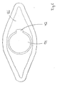
- the flow body 86 has the cross section of a rounded rhombus. It is understood that other forms can be useful.
- the screws on the insert can be released. Then the spindle can be removed with the flow body 86.
- the flow body 86 can be replaced and reused together with the spindle. In this way, the entire flange does not need to be removed.
Landscapes
- Engineering & Computer Science (AREA)
- Chemical & Material Sciences (AREA)
- Combustion & Propulsion (AREA)
- Mechanical Engineering (AREA)
- General Engineering & Computer Science (AREA)
- Crushing And Grinding (AREA)
- Cyclones (AREA)
Description
- Die Erfindung betrifft eine Mühlenanordnung zur Erzeugung von Kohlestaub, enthaltend die Merkmale nach Anspruch 1.
- Eine solche Mühlenanordnung dient dazu, Kohle zu Kohlestaub zu vermahlen. Dieser Kohlestaub wird über eine oder mehrere Staubleitungen einem Brenner zugeführt. In dem Brenner wird der Kohlestaub verbrannt und die erzeugte Wärme kann zum Beispiel bei der Stromerzeugung oder dergleichen nutzbar gemacht werden.
- Durch Optimierung des Verhältnisses von Brennstoff zu Luft in dem Brenner kann die Wärmegewinnung effizient gestaltet werden. Auch der Schadstoffausstoß, insbesondere von Stickoxiden (NOx), kann minimiert werden. Zu diesem Zweck ist die Staubmenge im Brenner zu kontrollieren.
- In einer Mühle bilden sich zum Beispiel durch die Maschine und verschiedene Einbauten unterschiedliche Strömungsverhältnisse aus. Auch Sperrluft mit zu geringer Temperatur oder Wasserdampfbildung beeinflussen die Strömungsverhältnisse. Dabei können sich Strähnen aus Kohlestaub bilden, die sich nicht auflösen. Die Strähnenbildung ist nicht steuerbar und es können keine Voraussagen über ihre Bildung gemacht werden. Dies führt zu einer ungleichmäßigen Staubverteilung auf die Staubleitungen. Den aus den Staubleitungen versorgten Brennern werden daher unterschiedliche Mengen an Brennstoff zugeführt. Das ist unerwünscht.
- Eine bekannte Mühleanordnung ist in
GB 828515 - Es ist auch bekannt, Blenden in den Staubleitungen anzuordnen. Mit den Blenden wird ein Widerstand eingesetzt, der die geförderte Staubmenge in der Staubleitung reduzieren soll. Diese Blenden liefern jedoch keine befriedigenden Ergebnisse.
- Es ist Aufgabe der Erfindung, eine Anordnung der eingangs genannten Art zu schaffen, mit der eine gleichmäßige Staubverteilung in den Staubleitungen und damit in den Brennern erreicht wird.
- Die Mühleanordnung wird so gebaut, dass die Mittel zur Beeinflussung der Staubströmung querschnittsverändernd ausgebildet sind und in der Mühle vor den Staubleitungen angeordnet sind. Eine solche Veränderung des wirksamen Strömungsquerschnitts kann zum Beispiel mit Blenden, Klappen oder dergleichen erreicht werden. Weiterhin weist die Mühle einen Sichter zur Trennung von groben und feinen Partikeln auf und die Mittel zur Beeinflussung der Staubströmung sind zwischen dem Sichter und dem Staubverteiler angeordnet. Somit wird die Strömung bereits vor der Verteilung auf die Staubleitungen beeinflusst. Es hat sich gezeigt, dass sich an dieser Stelle aufgrund der Sogwirkung die geförderte Staubmenge erhöht, wenn der Strömungsquerschnitt verringert wird. Umgekehrt kann die geförderte Staubmenge erniedrigt werden, wenn der Strömungsquerschnitt vergrößert wird. Die Veränderung muß also entgegengesetzt zu einer Veränderung mit bekannten Blenden in der Staubleitung vorgenommen werden.
- Erfindungsgemäß Können bestehende Anlagen mit dieser Anordnung aufgerüstet werden, der zur Beeinflussung der Staubströmung ausgestaltet ist. Ein solcher Flansch kann einen Fallrohrteil und einen koaxial um den Fallrohrteil herum angeordneten Gehäuseteil aufweisen, wodurch ein Ringraum gebildet wird, und der Ringraum kann mittels in radialer Richtung verlaufender Trennwände entsprechend der Aufteilung des Staubverteilers und der Anzahl der Staubleitungen segmentiert sein, wobei in jedem Segment zumindest eine Klappe vorgesehen ist, die von außen zwischen einer Stellung mit maximalem Querschnitt in Strömungsrichtung und einer Stellung mit minimalem Querschnitt in Strömungsrichtung einstellbar ist. Wird die Klappe eines Segments quer zur Strömungsrichtung gestellt, verringert sich der wirksame Strömungsquerschnitt. Die Strömungsgeschwindigkeit wird entsprechend in diesem Segment höher. Durch die so erzeugte Sogwirkung strömt mehr Staub in die Staubleitung. Umgekehrt kann die Klappe eines Segments parallel zur Strömungsrichtung ausgerichtet werden. Dann ist die Strömungsgeschwindigkeit niedriger und die geförderte Staubmenge ist geringer.
- Erfindungsgemäß sind die querschnittsbeeinflussenden Mittel von außen einstellbar. Eine weitere Möglichkeit der Einstellung der querschnittsbeeinflussenden Mittel ist, die Staubmenge mittels gebräuchlicher online - Meßverfahren in den Staubleitungen zu messen und die querschnittsbeeinflussenden Mittel automatisch zu regeln. Dann kann die Verteilung auch bei Veränderung der Strömungsverhältnisse angepasst werden. In einer Ausgestaltung der Erfindung sind die Mittel auswechselbar. Statt bestehende Anlagen mit einem Flansch nachzurüsten können die querschnittsverändernden Mittel auch in den Staubverteiler integriert werden.
- Die Mühle wird mit den o.g. Merkmalen mit folgenden Schritten betrieben:
- (i) Anordnen von querschnittsverändernden Elementen im Bereich des Staubverteilers,
- (ii) Verringern des Strömungsquerschnitts für Strömungen, bei denen zuwenig Staub in eine Staubleitung gelangt, und
- (iii) Vergrößern des Strömungsquerschnitts für Strömungen, bei denen zuviel Staub in eine Staubleitung gelangt.
- Es versteht sich, dass die Erfindung bei allen Arten von Mühlen verwirklicht werden kann, unabhängig davon, ob es sich um eine Vertikal- oder eine Rohrmühle handelt und unabhängig davon, ob ein statischer oder rotierender Sichter verwendet wird. Auch kann die Mahlgutaufgabe seitlich oder zentrisch vorgesehen sein.
- Ausgestaltungen der Erfindung sind Gegenstand des Unteransprüchs. Ein Ausführungsbeispiel ist nachstehend unter Bezugnahme auf die beigefügten Zeichnungen näher erläutert.
-
- Fig.1
- ist eine schematische Darstellung einer Vertikalmühlenanordnung mit Kugelringmühle
- Fig.2
- zeigt eine Strömungsleitanordnung im Detail
- Fig.3
- ist eine Draufsicht auf ein einzelnes Strömungsleitelement aus einer Strömungsleitanordnung aus
Fig.2 - Fig.4
- ist ein Querschnitt durch das Strömungsleitelement aus
Fig.2 - Fig.5
- zeigt einen Strömungskörper im Detail^
- Fig.6
- ist eine perspektivische Ansicht des Strömungsleitelements aus
Fig. 2 - Fig.7
- ist eine weitere perspektivische Ansicht des Strömungsleitelements aus
Fig.2 - In
Fig.1 ist eine allgemein mit 10 bezeichnete Mühlenanordnung dargestellt. Die Mühlenanordnung ist als Vertikalmühle mit zentrischer Mahlgutaufgabe 12 ausgebildet. Das Mahlgut gelangt durch ein Fallrohr in eine Kugelringmühle 14. Dies ist durch Pfeile 16 und 18 repräsentiert. In der Kugelringmühle 14 wird das Mahlgut radial nach aussen befördert und durch Kugeln 20 vermahlen. Dies ist durch Pfeile 22 und 24 repräsentiert. - An einem seitlichen Gasanschluß 26 wird ein Traggas durch einen Düsenring oder Düsenspalt in die Mühle geströmt. Dies ist durch einen Pfeil 28 repräsentiert. Das Gas strömt in einen Ringraum um die Kugelringmühle 14. Dort wird das Mahlgut von dem Gasstrom erfasst. Der Gasstrom fördert das Mahlgut aussen nach oben in Richtung des mit 30 bezeichneten Pfeils. Mit dem Gas wird der erzeugte Mahlstaub getrocknet und gefördert.
- Der Mahlstaub wird zu einem statischen oder rotierenden Sichter 32 und den daran angeschlossenen Staubleitungen 34 gefördert. In dem Sichter fallen Grobpartikel über einen Grießrücklaufkonus 44 zum Zentrum hin nach unten auf den Mahlteller 46. Dies ist durch einen Pfeil 36 repräsentiert. Mahlgut, das in ausreichendem Maß zu Feinstaub zermahlen wurde, strömt in Richtung des Pfeils 38 nach oben. In einem Staubverteiler 40 wird der Feinstaub auf die Staubleitungen verteilt.
- Zwischen dem Staubverteiler 40 und dem Sichter 32 ist eine Strömungsleitanordnung 42 angeordnet.
- Die Strömungsleitanordnung 42 ist in
Fig.2 im Detail dargestellt. Die Strömungsleitanordnung 42 ist als Flansch ausgebildet und wird fest oberhalb des Sichters 32 mit dem Staubverteiler 40 verschraubt. Zu diesem Zweck sind Bohrungen 48 vorgesehen. Auf diese Weise können bestehende Mühlen mit einer solchen Strömungsleitanordnung 42 nachgcrüstct werden. Ansonsten kann die Strömungsleitanordnung 42 in den Staubverteiler 40 integriert werden. Die Strömungsleitanordnung 42 umfasst einen innen liegenden, zylindrischen Teil 50 des Fallrohrs 12. Konzentrisch zu dem Fallrohr 12 ist ein zylindrisches Außengehäuse 52 vorgesehen. Zwischen dem Fallrohrteil 50 und dem Außengehäuse 52 ist ein Ringraum 54 gebildet. Durch radial verlaufende Wandungen 56, 58, 60 und 62 wird der Ringraum in vier Segmente 64, 66, 68 und 70 aufgeteilt. In eingebautem Zustand sind die Segmente 64, 66, 68 und 70 strömungsmäßig vollständig voneinander getrennt. Staub, der durch eines dieser Segmente gelangt, wird durch den Staubverteiler 40 einer definierten Staubleitung zugeführt. - Der wirksame Querschnitt für die durch z.B. das Segment 64 strömende Staubströmung ist in
Fig.2 fett dargestellt. Er wird durch die Wandungen 56 und 58, sowie die entsprechenden Teile des Fallrohrs 50 und des Gehäuses begrenzt. - In
Fig.2 sind schematisch Strömungsleitelemente 72 gezeigt, mit denen der Strömungsquerschnitt beeinflusst werden kann. Zu diesem Zweck sind außen Betätigungselemente 74 vorgesehen. In jedem der Segmente 64, 66, 68 und 70 sind zwei solcher Strömungsleitelemente 72 vorgesehen. Die Strömungsleitelemente 72 sind so ausgebildet, dass mit ihnen eine Verringerung des Querschnitts um einen vorgegebenen Prozentsatz erreicht werden kann. -
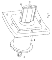
Fig. 3 und 4 zeigen ein Strömungsleitelement 72 im Detail. Das Strömungsleitelement umfasst eine Welle 76. Die Welle 76 ist rotationssymmetrisch ausgebildet. Sie erstreckt sich durch einen Einsatz 78 hindurch vom Außenraum des Gehäuses 52 in den Strömungskanal im Ringraum 54. Der Einsatz 78 ist quadratisch ausgebildet und mit Schrauben 82 in einem korrespondierenden Fenster im Gehäuse 52 eingesetzt und verschraubt. Dabei ist die Anordnung so ausgebildet, daß keine Vorsprünge oder Kanten im Strömungskanal entstehen. Am innenliegenden Ende 84 der Welle ist ein Strömungskörper 86 aufgesteckt. Die dafür vorgesehene Bohrung 94 im Strömungskörper 86 ist mit einer Nut 92 (Fig.5 ) versehen, in die eine an der Welle vorgesehene Paßfeder eingreift. In axialer Richtung wird der Strömungskörper 86 mit einer Schraube 88 an die Spindel geschraubt. Das Strömungelement erstreckt sich bis an den Fallrohrteil 50, jedoch ohne diesen zu berühren. - Am entgegengesetzten Ende 90 der Spindel ist ein Mehrkant 96 vorgesehen. Mit einem geeigneten Werkzeug kann die Spindel an dem Mehrkant 96 um eine Achse 98 (
Fig.3 ) rotiert werden. Dabei wird der Strömungskörper 86 ebenfalls rotiert. Je nach Lage hat der Strömungskörper eine größere Ausdehnung quer zur Strömungsrichtung oder nicht. Die Welle 76 ist in einem Gehäuse 100 gelagert. Das Gehäuse 100 weist eine Anzeige mit einer Skala 102 auf. Ein fest mit der Welle 76 verbundener Zeiger 104 zeigt so die Stellung des Strömungskörpers 80 an. - Im vorliegenden Ausführungsbeispiel hat der Strömungskörper 86 den Querschnitt einer abgerundeten Raute. Es versteht sich, dass auch andere Formen sinnvoll sein können. Bei Abnutzung des Strömungselements können die Schrauben an dem Einsatz gelöst werden. Dann kann die Spindel mit dem Strömungskörper 86 entnommen werden. Der Strömungskörper 86 kann ausgetauscht und zusammen mit der Spindel wieder eingesetzt werden. Auf diese Weise braucht nicht der gesamte Flansch ausgebaut werden.
Claims (2)
- Mühlenanordnung (10) zur Erzeugung von Kohlestaub, enthaltend(a) eine Mühle (14),(b) eine Mehrzahl von Staubleitungen (34), welche Kohlestaub von der Mühle zu einem Brenner leiten,(c) einen Sichter (32) zur Trennung von groben und feinen Partikeln,(d) einen strömungsmäßig zwischen dem Sichter und den Staubleitungen angeordneten Staubverteiler (40) zur Verteilung des aus den im Sichter abgetrennten, feinen Partikeln bestehenden Kohlestaubs auf die Staubleitungen, und(e) Mittel (42) zur Beeinflussung der Staubströmung in den Staubleitungen, welche zwischen dem Sichter (32) und dem Staubverteiler (40) angeordnet sind(f) wobei die Mittel zur Beeinflussung der Staubströmung querschnittsverändernd ausgebildet sind und in der Mühlenanordnung vor den Staubleitungen angeordnet sind,
dadurch gekennzeichnet, dass(g) die Mittel zur Beeinflussung der Staubströmung von einem Flansch gebildet sind, der einen Fallrohrteil (50) und einen koaxial um den Fallrohrteil herum angeordneten Gehäuseteil (80) aufweist, wodurch ein Ringraum (54) gebildet wird, und der Ringraum mittels in radialer Richtung verlaufender Trennwände (56, 58, 60, 62) entsprechend der Aufteilung des Staubverteilers und der Anzahl der Staubleitungen segmentiert ist, wobei in jedem Segment (64, 66, 68, 70) zumindest eine Klappe (86) vorgesehen ist, die von außen zwischen einer Stellung mit maximalem Querschnitt in Strömungsrichtung und einer Stellung mit minimalem Querschnitt in Strömungsrichtung einstellbar ist. - Mühlenanordnung nach Anspruch 1, dadurch gekennzeichnet, daß die Mittel (86) zur Beeinflussung der Staubströmung in den Staubleitungen auswechselbar sind.
Applications Claiming Priority (2)
| Application Number | Priority Date | Filing Date | Title |
|---|---|---|---|
| DE102006042060.8A DE102006042060B4 (de) | 2006-09-05 | 2006-09-05 | Mühlenanordnung mit gleichmäßiger Staubverteilung und Verfahren zum Betrieb einer Mühlenanordnung |
| PCT/EP2007/057848 WO2008028727A1 (de) | 2006-09-05 | 2007-07-30 | Mühlenanordnung mit gleichmässiger staubverteilung und verfahren zum betrieb einer mühlenanordnung |
Publications (3)
| Publication Number | Publication Date |
|---|---|
| EP2059722A1 EP2059722A1 (de) | 2009-05-20 |
| EP2059722B1 true EP2059722B1 (de) | 2013-12-18 |
| EP2059722B8 EP2059722B8 (de) | 2014-02-19 |
Family
ID=38646586
Family Applications (1)
| Application Number | Title | Priority Date | Filing Date |
|---|---|---|---|
| EP07788048.2A Not-in-force EP2059722B8 (de) | 2006-09-05 | 2007-07-30 | Mühlenanordnung mit gleichmässiger staubverteilung und verfahren zum betrieb einer mühlenanordnung |
Country Status (5)
| Country | Link |
|---|---|
| EP (1) | EP2059722B8 (de) |
| AU (1) | AU2007294069B2 (de) |
| DE (1) | DE102006042060B4 (de) |
| WO (1) | WO2008028727A1 (de) |
| ZA (1) | ZA200901738B (de) |
Families Citing this family (1)
| Publication number | Priority date | Publication date | Assignee | Title |
|---|---|---|---|---|
| DE102010038628A1 (de) | 2010-07-29 | 2012-02-02 | Hitachi Power Europe Gmbh | Mühlenvorrichtung und Verfahren zur Beeinflussung der Staubverteilung auf die Staubleitungen einer Mühle |
Family Cites Families (7)
| Publication number | Priority date | Publication date | Assignee | Title |
|---|---|---|---|---|
| GB311872A (en) * | 1928-03-22 | 1929-05-23 | Edward William Green | Improvements in and relating to the supply of pulverized fuel to burners |
| GB828515A (en) * | 1957-03-06 | 1960-02-17 | Babcock & Wilcox Ltd | Improvements in or relating to pulverisers |
| DE1152054B (de) | 1961-12-22 | 1963-07-25 | Kohlenscheidungs Ges Mit Besch | Einrichtung zum gleichmaessigen Verteilen eines Staub-Foerderluft-Gemisches auf mehrere Abzweigleitungen |
| US6186079B1 (en) | 1999-08-31 | 2001-02-13 | Sure Alloy Steel Corporation | Linear diffuser for balancing coal flow |
| US6481361B1 (en) | 1999-09-09 | 2002-11-19 | Rjm Corporation | Coal balancing damper |
| DE10317437A1 (de) * | 2003-04-15 | 2004-10-28 | Babcock Borsig Power Systems Gmbh | Walzen- oder Walzenschüsselmühle |
| US7017501B2 (en) | 2004-01-22 | 2006-03-28 | Alstom Technology Ltd | Riffle distributor assembly for a fossil fuel fired combustion arrangement |
-
2006
- 2006-09-05 DE DE102006042060.8A patent/DE102006042060B4/de not_active Expired - Fee Related
-
2007
- 2007-07-30 AU AU2007294069A patent/AU2007294069B2/en not_active Ceased
- 2007-07-30 ZA ZA200901738A patent/ZA200901738B/xx unknown
- 2007-07-30 WO PCT/EP2007/057848 patent/WO2008028727A1/de not_active Ceased
- 2007-07-30 EP EP07788048.2A patent/EP2059722B8/de not_active Not-in-force
Also Published As
| Publication number | Publication date |
|---|---|
| DE102006042060B4 (de) | 2018-05-09 |
| ZA200901738B (en) | 2010-06-30 |
| EP2059722B8 (de) | 2014-02-19 |
| WO2008028727A1 (de) | 2008-03-13 |
| AU2007294069B2 (en) | 2011-08-11 |
| AU2007294069A1 (en) | 2008-03-13 |
| DE102006042060A1 (de) | 2008-03-13 |
| EP2059722A1 (de) | 2009-05-20 |
Similar Documents
| Publication | Publication Date | Title |
|---|---|---|
| DE4423815C2 (de) | Mühlensichter | |
| EP2066461B1 (de) | Zentrifugalsichter | |
| EP1239966A1 (de) | Mühlensichter | |
| DE102008038776A1 (de) | Verfahren zur Sichtung eines Mahlgut-Fluid-Gemisches und Mühlensichter | |
| EP2804696B1 (de) | Verfahren und vertikalmühle zum mahlen von mahlgut | |
| EP2657599A1 (de) | Brenner für staub- und/oder partikelförmige Brennstoffe mit veränderlichem Drall | |
| EP2985081B1 (de) | Verfahren und Luftstrom-Vertikalmühle zur Mahlung von heißem und feuchtem Rohmaterial sowie kanalartiges Segment | |
| EP3274112A1 (de) | Formsandkühler | |
| EP1153661B1 (de) | Mühlensichter | |
| EP0165429B1 (de) | Verfahren zum Betrieb einer Mahlanlage sowie nach diesem Verfahren arbeitende Mahlanlage | |
| DE102006042060B4 (de) | Mühlenanordnung mit gleichmäßiger Staubverteilung und Verfahren zum Betrieb einer Mühlenanordnung | |
| DE1910501A1 (de) | Umluftsichter | |
| EP3849714B1 (de) | Sichtrad mit segelflächenelementen und verfahren zum sichten mit einem solchen sichtrad | |
| EP0492062B1 (de) | Windsichter | |
| DE2220534A1 (de) | Drehstroemungswirbler zur sichtung und abscheidung feinkoerniger partikel | |
| DE3040603C2 (de) | Zentrifugalabscheider | |
| DE3124571A1 (de) | Vorrichtung zum verteilen von brennstoffstaub an kanaele von brennern | |
| DE102004019109A1 (de) | Sichterklappenbetätigung | |
| DE908096C (de) | Windsichter | |
| DE1062532B (de) | Rohrmuehle fuer Mahltrocknung | |
| DE19708956A1 (de) | Sichter | |
| DE544449C (de) | Walzenmahlkoerper fuer Rohr- und aehnliche Muehlen | |
| EP4063029B1 (de) | Zentrifugalkraft-windsichter und verfahren zur sichtung von staubförmigen gütern | |
| EP2361687B1 (de) | Verfahren zur Herstellung einer Rohrmühle | |
| WO2018162173A1 (de) | Sichteinrichtung und verfahren zum sichten eines materialstroms |
Legal Events
| Date | Code | Title | Description |
|---|---|---|---|
| PUAI | Public reference made under article 153(3) epc to a published international application that has entered the european phase |
Free format text: ORIGINAL CODE: 0009012 |
|
| 17P | Request for examination filed |
Effective date: 20090127 |
|
| AK | Designated contracting states |
Kind code of ref document: A1 Designated state(s): AT BE BG CH CY CZ DE DK EE ES FI FR GB GR HU IE IS IT LI LT LU LV MC MT NL PL PT RO SE SI SK TR |
|
| AX | Request for extension of the european patent |
Extension state: AL BA HR MK RS |
|
| DAX | Request for extension of the european patent (deleted) | ||
| 17Q | First examination report despatched |
Effective date: 20130305 |
|
| GRAP | Despatch of communication of intention to grant a patent |
Free format text: ORIGINAL CODE: EPIDOSNIGR1 |
|
| INTG | Intention to grant announced |
Effective date: 20130726 |
|
| GRAS | Grant fee paid |
Free format text: ORIGINAL CODE: EPIDOSNIGR3 |
|
| GRAA | (expected) grant |
Free format text: ORIGINAL CODE: 0009210 |
|
| AK | Designated contracting states |
Kind code of ref document: B1 Designated state(s): AT BE BG CH CY CZ DE DK EE ES FI FR GB GR HU IE IS IT LI LT LU LV MC MT NL PL PT RO SE SI SK TR |
|
| REG | Reference to a national code |
Ref country code: GB Ref legal event code: FG4D Free format text: NOT ENGLISH |
|
| REG | Reference to a national code |
Ref country code: CH Ref legal event code: EP |
|
| RAP2 | Party data changed (patent owner data changed or rights of a patent transferred) |
Owner name: BABCOCK BORSIG STEINMUELLER GMBH |
|
| REG | Reference to a national code |
Ref country code: AT Ref legal event code: REF Ref document number: 645803 Country of ref document: AT Kind code of ref document: T Effective date: 20140115 |
|
| REG | Reference to a national code |
Ref country code: IE Ref legal event code: FG4D Free format text: LANGUAGE OF EP DOCUMENT: GERMAN |
|
| REG | Reference to a national code |
Ref country code: DE Ref legal event code: R096 Ref document number: 502007012613 Country of ref document: DE Effective date: 20140206 |
|
| REG | Reference to a national code |
Ref country code: NL Ref legal event code: VDEP Effective date: 20131218 |
|
| PG25 | Lapsed in a contracting state [announced via postgrant information from national office to epo] |
Ref country code: FI Free format text: LAPSE BECAUSE OF FAILURE TO SUBMIT A TRANSLATION OF THE DESCRIPTION OR TO PAY THE FEE WITHIN THE PRESCRIBED TIME-LIMIT Effective date: 20131218 Ref country code: SE Free format text: LAPSE BECAUSE OF FAILURE TO SUBMIT A TRANSLATION OF THE DESCRIPTION OR TO PAY THE FEE WITHIN THE PRESCRIBED TIME-LIMIT Effective date: 20131218 Ref country code: LT Free format text: LAPSE BECAUSE OF FAILURE TO SUBMIT A TRANSLATION OF THE DESCRIPTION OR TO PAY THE FEE WITHIN THE PRESCRIBED TIME-LIMIT Effective date: 20131218 |
|
| REG | Reference to a national code |
Ref country code: LT Ref legal event code: MG4D |
|
| PG25 | Lapsed in a contracting state [announced via postgrant information from national office to epo] |
Ref country code: LV Free format text: LAPSE BECAUSE OF FAILURE TO SUBMIT A TRANSLATION OF THE DESCRIPTION OR TO PAY THE FEE WITHIN THE PRESCRIBED TIME-LIMIT Effective date: 20131218 |
|
| PG25 | Lapsed in a contracting state [announced via postgrant information from national office to epo] |
Ref country code: IS Free format text: LAPSE BECAUSE OF FAILURE TO SUBMIT A TRANSLATION OF THE DESCRIPTION OR TO PAY THE FEE WITHIN THE PRESCRIBED TIME-LIMIT Effective date: 20140418 Ref country code: EE Free format text: LAPSE BECAUSE OF FAILURE TO SUBMIT A TRANSLATION OF THE DESCRIPTION OR TO PAY THE FEE WITHIN THE PRESCRIBED TIME-LIMIT Effective date: 20131218 |
|
| PG25 | Lapsed in a contracting state [announced via postgrant information from national office to epo] |
Ref country code: RO Free format text: LAPSE BECAUSE OF FAILURE TO SUBMIT A TRANSLATION OF THE DESCRIPTION OR TO PAY THE FEE WITHIN THE PRESCRIBED TIME-LIMIT Effective date: 20131218 Ref country code: PT Free format text: LAPSE BECAUSE OF FAILURE TO SUBMIT A TRANSLATION OF THE DESCRIPTION OR TO PAY THE FEE WITHIN THE PRESCRIBED TIME-LIMIT Effective date: 20140418 Ref country code: NL Free format text: LAPSE BECAUSE OF FAILURE TO SUBMIT A TRANSLATION OF THE DESCRIPTION OR TO PAY THE FEE WITHIN THE PRESCRIBED TIME-LIMIT Effective date: 20131218 Ref country code: PL Free format text: LAPSE BECAUSE OF FAILURE TO SUBMIT A TRANSLATION OF THE DESCRIPTION OR TO PAY THE FEE WITHIN THE PRESCRIBED TIME-LIMIT Effective date: 20131218 Ref country code: CZ Free format text: LAPSE BECAUSE OF FAILURE TO SUBMIT A TRANSLATION OF THE DESCRIPTION OR TO PAY THE FEE WITHIN THE PRESCRIBED TIME-LIMIT Effective date: 20131218 Ref country code: CY Free format text: LAPSE BECAUSE OF FAILURE TO SUBMIT A TRANSLATION OF THE DESCRIPTION OR TO PAY THE FEE WITHIN THE PRESCRIBED TIME-LIMIT Effective date: 20131218 Ref country code: ES Free format text: LAPSE BECAUSE OF FAILURE TO SUBMIT A TRANSLATION OF THE DESCRIPTION OR TO PAY THE FEE WITHIN THE PRESCRIBED TIME-LIMIT Effective date: 20131218 Ref country code: SK Free format text: LAPSE BECAUSE OF FAILURE TO SUBMIT A TRANSLATION OF THE DESCRIPTION OR TO PAY THE FEE WITHIN THE PRESCRIBED TIME-LIMIT Effective date: 20131218 |
|
| REG | Reference to a national code |
Ref country code: DE Ref legal event code: R097 Ref document number: 502007012613 Country of ref document: DE |
|
| PLBE | No opposition filed within time limit |
Free format text: ORIGINAL CODE: 0009261 |
|
| STAA | Information on the status of an ep patent application or granted ep patent |
Free format text: STATUS: NO OPPOSITION FILED WITHIN TIME LIMIT |
|
| PG25 | Lapsed in a contracting state [announced via postgrant information from national office to epo] |
Ref country code: DK Free format text: LAPSE BECAUSE OF FAILURE TO SUBMIT A TRANSLATION OF THE DESCRIPTION OR TO PAY THE FEE WITHIN THE PRESCRIBED TIME-LIMIT Effective date: 20131218 |
|
| 26N | No opposition filed |
Effective date: 20140919 |
|
| REG | Reference to a national code |
Ref country code: DE Ref legal event code: R097 Ref document number: 502007012613 Country of ref document: DE Effective date: 20140919 |
|
| PG25 | Lapsed in a contracting state [announced via postgrant information from national office to epo] |
Ref country code: LU Free format text: LAPSE BECAUSE OF FAILURE TO SUBMIT A TRANSLATION OF THE DESCRIPTION OR TO PAY THE FEE WITHIN THE PRESCRIBED TIME-LIMIT Effective date: 20140730 |
|
| REG | Reference to a national code |
Ref country code: CH Ref legal event code: PL |
|
| REG | Reference to a national code |
Ref country code: IE Ref legal event code: MM4A |
|
| REG | Reference to a national code |
Ref country code: FR Ref legal event code: ST Effective date: 20150331 |
|
| PG25 | Lapsed in a contracting state [announced via postgrant information from national office to epo] |
Ref country code: CH Free format text: LAPSE BECAUSE OF NON-PAYMENT OF DUE FEES Effective date: 20140731 Ref country code: LI Free format text: LAPSE BECAUSE OF NON-PAYMENT OF DUE FEES Effective date: 20140731 |
|
| PG25 | Lapsed in a contracting state [announced via postgrant information from national office to epo] |
Ref country code: FR Free format text: LAPSE BECAUSE OF NON-PAYMENT OF DUE FEES Effective date: 20140731 Ref country code: SI Free format text: LAPSE BECAUSE OF FAILURE TO SUBMIT A TRANSLATION OF THE DESCRIPTION OR TO PAY THE FEE WITHIN THE PRESCRIBED TIME-LIMIT Effective date: 20131218 |
|
| PG25 | Lapsed in a contracting state [announced via postgrant information from national office to epo] |
Ref country code: IE Free format text: LAPSE BECAUSE OF NON-PAYMENT OF DUE FEES Effective date: 20140730 |
|
| REG | Reference to a national code |
Ref country code: AT Ref legal event code: MM01 Ref document number: 645803 Country of ref document: AT Kind code of ref document: T Effective date: 20140730 |
|
| PG25 | Lapsed in a contracting state [announced via postgrant information from national office to epo] |
Ref country code: AT Free format text: LAPSE BECAUSE OF NON-PAYMENT OF DUE FEES Effective date: 20140730 |
|
| PG25 | Lapsed in a contracting state [announced via postgrant information from national office to epo] |
Ref country code: MC Free format text: LAPSE BECAUSE OF FAILURE TO SUBMIT A TRANSLATION OF THE DESCRIPTION OR TO PAY THE FEE WITHIN THE PRESCRIBED TIME-LIMIT Effective date: 20131218 |
|
| PG25 | Lapsed in a contracting state [announced via postgrant information from national office to epo] |
Ref country code: BG Free format text: LAPSE BECAUSE OF FAILURE TO SUBMIT A TRANSLATION OF THE DESCRIPTION OR TO PAY THE FEE WITHIN THE PRESCRIBED TIME-LIMIT Effective date: 20131218 |
|
| PG25 | Lapsed in a contracting state [announced via postgrant information from national office to epo] |
Ref country code: GR Free format text: LAPSE BECAUSE OF FAILURE TO SUBMIT A TRANSLATION OF THE DESCRIPTION OR TO PAY THE FEE WITHIN THE PRESCRIBED TIME-LIMIT Effective date: 20140319 Ref country code: IT Free format text: LAPSE BECAUSE OF FAILURE TO SUBMIT A TRANSLATION OF THE DESCRIPTION OR TO PAY THE FEE WITHIN THE PRESCRIBED TIME-LIMIT Effective date: 20131218 Ref country code: MT Free format text: LAPSE BECAUSE OF FAILURE TO SUBMIT A TRANSLATION OF THE DESCRIPTION OR TO PAY THE FEE WITHIN THE PRESCRIBED TIME-LIMIT Effective date: 20131218 |
|
| PG25 | Lapsed in a contracting state [announced via postgrant information from national office to epo] |
Ref country code: TR Free format text: LAPSE BECAUSE OF FAILURE TO SUBMIT A TRANSLATION OF THE DESCRIPTION OR TO PAY THE FEE WITHIN THE PRESCRIBED TIME-LIMIT Effective date: 20131218 Ref country code: HU Free format text: LAPSE BECAUSE OF FAILURE TO SUBMIT A TRANSLATION OF THE DESCRIPTION OR TO PAY THE FEE WITHIN THE PRESCRIBED TIME-LIMIT; INVALID AB INITIO Effective date: 20070730 Ref country code: BE Free format text: LAPSE BECAUSE OF FAILURE TO SUBMIT A TRANSLATION OF THE DESCRIPTION OR TO PAY THE FEE WITHIN THE PRESCRIBED TIME-LIMIT Effective date: 20140731 |
|
| PGFP | Annual fee paid to national office [announced via postgrant information from national office to epo] |
Ref country code: DE Payment date: 20190926 Year of fee payment: 13 |
|
| PGFP | Annual fee paid to national office [announced via postgrant information from national office to epo] |
Ref country code: GB Payment date: 20190725 Year of fee payment: 13 |
|
| REG | Reference to a national code |
Ref country code: DE Ref legal event code: R119 Ref document number: 502007012613 Country of ref document: DE |
|
| GBPC | Gb: european patent ceased through non-payment of renewal fee |
Effective date: 20200730 |
|
| PG25 | Lapsed in a contracting state [announced via postgrant information from national office to epo] |
Ref country code: GB Free format text: LAPSE BECAUSE OF NON-PAYMENT OF DUE FEES Effective date: 20200730 |
|
| PG25 | Lapsed in a contracting state [announced via postgrant information from national office to epo] |
Ref country code: DE Free format text: LAPSE BECAUSE OF NON-PAYMENT OF DUE FEES Effective date: 20210202 |