EP2055925B1 - Soupapes de dosage d'injection de carburant - Google Patents
Soupapes de dosage d'injection de carburant Download PDFInfo
- Publication number
- EP2055925B1 EP2055925B1 EP20070254369 EP07254369A EP2055925B1 EP 2055925 B1 EP2055925 B1 EP 2055925B1 EP 20070254369 EP20070254369 EP 20070254369 EP 07254369 A EP07254369 A EP 07254369A EP 2055925 B1 EP2055925 B1 EP 2055925B1
- Authority
- EP
- European Patent Office
- Prior art keywords
- fuel
- pressure
- fuel injection
- valving
- accumulator volume
- Prior art date
- Legal status (The legal status is an assumption and is not a legal conclusion. Google has not performed a legal analysis and makes no representation as to the accuracy of the status listed.)
- Not-in-force
Links
Images

Classifications
-
- F—MECHANICAL ENGINEERING; LIGHTING; HEATING; WEAPONS; BLASTING
- F02—COMBUSTION ENGINES; HOT-GAS OR COMBUSTION-PRODUCT ENGINE PLANTS
- F02M—SUPPLYING COMBUSTION ENGINES IN GENERAL WITH COMBUSTIBLE MIXTURES OR CONSTITUENTS THEREOF
- F02M43/00—Fuel-injection apparatus operating simultaneously on two or more fuels, or on a liquid fuel and another liquid, e.g. the other liquid being an anti-knock additive
-
- F—MECHANICAL ENGINEERING; LIGHTING; HEATING; WEAPONS; BLASTING
- F02—COMBUSTION ENGINES; HOT-GAS OR COMBUSTION-PRODUCT ENGINE PLANTS
- F02M—SUPPLYING COMBUSTION ENGINES IN GENERAL WITH COMBUSTIBLE MIXTURES OR CONSTITUENTS THEREOF
- F02M59/00—Pumps specially adapted for fuel-injection and not provided for in groups F02M39/00 -F02M57/00, e.g. rotary cylinder-block type of pumps
- F02M59/20—Varying fuel delivery in quantity or timing
- F02M59/36—Varying fuel delivery in quantity or timing by variably-timed valves controlling fuel passages to pumping elements or overflow passages
-
- F—MECHANICAL ENGINEERING; LIGHTING; HEATING; WEAPONS; BLASTING
- F02—COMBUSTION ENGINES; HOT-GAS OR COMBUSTION-PRODUCT ENGINE PLANTS
- F02M—SUPPLYING COMBUSTION ENGINES IN GENERAL WITH COMBUSTIBLE MIXTURES OR CONSTITUENTS THEREOF
- F02M63/00—Other fuel-injection apparatus having pertinent characteristics not provided for in groups F02M39/00 - F02M57/00 or F02M67/00; Details, component parts, or accessories of fuel-injection apparatus, not provided for in, or of interest apart from, the apparatus of groups F02M39/00 - F02M61/00 or F02M67/00; Combination of fuel pump with other devices, e.g. lubricating oil pump
- F02M63/0012—Valves
- F02M63/0014—Valves characterised by the valve actuating means
- F02M63/0028—Valves characterised by the valve actuating means hydraulic
-
- F—MECHANICAL ENGINEERING; LIGHTING; HEATING; WEAPONS; BLASTING
- F02—COMBUSTION ENGINES; HOT-GAS OR COMBUSTION-PRODUCT ENGINE PLANTS
- F02M—SUPPLYING COMBUSTION ENGINES IN GENERAL WITH COMBUSTIBLE MIXTURES OR CONSTITUENTS THEREOF
- F02M63/00—Other fuel-injection apparatus having pertinent characteristics not provided for in groups F02M39/00 - F02M57/00 or F02M67/00; Details, component parts, or accessories of fuel-injection apparatus, not provided for in, or of interest apart from, the apparatus of groups F02M39/00 - F02M61/00 or F02M67/00; Combination of fuel pump with other devices, e.g. lubricating oil pump
- F02M63/0012—Valves
- F02M63/0031—Valves characterized by the type of valves, e.g. special valve member details, valve seat details, valve housing details
- F02M63/004—Sliding valves, e.g. spool valves, i.e. whereby the closing member has a sliding movement along a seat for opening and closing
-
- F—MECHANICAL ENGINEERING; LIGHTING; HEATING; WEAPONS; BLASTING
- F02—COMBUSTION ENGINES; HOT-GAS OR COMBUSTION-PRODUCT ENGINE PLANTS
- F02M—SUPPLYING COMBUSTION ENGINES IN GENERAL WITH COMBUSTIBLE MIXTURES OR CONSTITUENTS THEREOF
- F02M63/00—Other fuel-injection apparatus having pertinent characteristics not provided for in groups F02M39/00 - F02M57/00 or F02M67/00; Details, component parts, or accessories of fuel-injection apparatus, not provided for in, or of interest apart from, the apparatus of groups F02M39/00 - F02M61/00 or F02M67/00; Combination of fuel pump with other devices, e.g. lubricating oil pump
- F02M63/02—Fuel-injection apparatus having several injectors fed by a common pumping element, or having several pumping elements feeding a common injector; Fuel-injection apparatus having provisions for cutting-out pumps, pumping elements, or injectors; Fuel-injection apparatus having provisions for variably interconnecting pumping elements and injectors alternatively
- F02M63/0225—Fuel-injection apparatus having a common rail feeding several injectors ; Means for varying pressure in common rails; Pumps feeding common rails
- F02M63/0275—Arrangement of common rails
- F02M63/0285—Arrangement of common rails having more than one common rail
- F02M63/029—Arrangement of common rails having more than one common rail per cylinder bank, e.g. storing different fuels or fuels at different pressure levels per cylinder bank
-
- F—MECHANICAL ENGINEERING; LIGHTING; HEATING; WEAPONS; BLASTING
- F02—COMBUSTION ENGINES; HOT-GAS OR COMBUSTION-PRODUCT ENGINE PLANTS
- F02M—SUPPLYING COMBUSTION ENGINES IN GENERAL WITH COMBUSTIBLE MIXTURES OR CONSTITUENTS THEREOF
- F02M2200/00—Details of fuel-injection apparatus, not otherwise provided for
- F02M2200/95—Fuel injection apparatus operating on particular fuels, e.g. biodiesel, ethanol, mixed fuels
-
- Y—GENERAL TAGGING OF NEW TECHNOLOGICAL DEVELOPMENTS; GENERAL TAGGING OF CROSS-SECTIONAL TECHNOLOGIES SPANNING OVER SEVERAL SECTIONS OF THE IPC; TECHNICAL SUBJECTS COVERED BY FORMER USPC CROSS-REFERENCE ART COLLECTIONS [XRACs] AND DIGESTS
- Y10—TECHNICAL SUBJECTS COVERED BY FORMER USPC
- Y10T—TECHNICAL SUBJECTS COVERED BY FORMER US CLASSIFICATION
- Y10T137/00—Fluid handling
- Y10T137/2496—Self-proportioning or correlating systems
Definitions
- the invention relates to fuel injection metering valves and particularly, but not exclusively, to fuel injection metering valves for use in dual-fuel fuel injection systems.
- HCCI Homogeneous Charge Compression Ignition
- a solution to this problem would be to have a fuel injection system able to change between different fuels for different operating conditions. With the currently known technology this would entail having two separate injection systems with dedicated injector sets, inlet metering valves, pressure regulators and fuel pumps. This would be very expensive for automotive use and may give rise to space and/or weight problems.
- the invention provides a fuel injection metering valve having a first fuel outlet for supplying fuel to a first accumulator volume, a second fuel outlet for supplying fuel to a second accumulator volume, valving for controlling fuel flow to said first and second fuel outlets, a first flow path for exposing said valving to a fuel pressure representative of fuel pressure in said first accumulator volume and a second flow path for exposing said valving to fuel pressure representative of fuel pressure in said second accumulator volume; said valving being responsive to said representative fuel pressures to control the fuel supply (or fuel flow rate) from said second fuel outlet to said second accumulator volume as a function of the fuel pressure in said first accumulator volume.
- the fuel injection metering valve is arranged in such a way that: to reduce the pressure in one of said first or second accumulator volumes, the metering valve acts to decrease the fuel supply from said first or second fuel outlets, respectively (for example, by restricting the fuel flow rate through the valve to the first or second fuel outlet); and to increase the pressure in one of said first or second accumulator volumes, the metering valve acts to increase the fuel supply from said first or second fuel outlets, respectively (for example, by increasing the fuel flow rate through the valve to the first or second fuel outlet).
- US 2006/0180124 relates to an accumulator spill valve assembly for regulating the amount of fuel delivered from a fuel pump to an accumulator volume in each pumping stroke of a fuel pump.
- the spill valve assembly includes two outlets, one to an accumulator and one to a low pressure fuel tank.
- a feedback mechanism responsive to fuel pressure in the accumulator volume is employed, such that when a sufficient quantity of fuel has been delivered to the accumulator volume the outlet to the accumulator volume is shut off and pressurised fuel is dumped via the second outlet to low pressure.
- the invention also includes a fuel pump having an integral fuel injection metering valve as described herein, said pump comprising pumping means for separately pumping and outputting respective fuel flows received from said first and second fuel outlets.
- the invention further includes a fuel injection system comprising a fuel injection metering valve configured, in use, to supply a first fuel output and a second fuel output to a first accumulator volume and a second accumulator volume, respectively; and having valving in flow communication with respective flow paths that, in use, expose respective pressure receiving portions of the valving to respective fuel pressure flows indicative of the fuel pressures in said first and second accumulator volumes; said valving being responsive to said pressure flows to cause the fuel pressure in said second accumulator volume to follow the fuel pressure in the first accumulator volume.
- the fuel injection metering valve within the fuel injection system of the invention is as described in relation to the first aspect of the invention.
- the invention provides a fuel delivery system comprising a fuel injection system of the invention.
- the invention provides a method of controlling fuel pressure in a fuel injection system, said method comprising pumping a first fuel from a fuel reservoir into a first accumulator volume, pumping a second fuel from a second fuel reservoir into a second accumulator volume, setting a delivery pressure for said first fuel from said first accumulator volume, exposing a valve member to a source of said first fuel that is at a pressure indicative of said delivery pressure and exposing said valve member to a source of said second fuel at a pressure indicative of a delivery pressure of said second fuel; said valve member being operable to respond to the respective pressures indicative of delivery pressure to cause the delivery pressure of said second fuel to be substantially maintained in fixed relation to the delivery pressure of said first fuel.
- a dual-fuel fuel delivery system for an automobile comprises an injection system 10 a first fuel reservoir 12 and a second fuel reservoir 14.
- the first fuel reservoir 12 will be described as a petrol reservoir and the second fuel reservoir 14 will be described as a diesel fuel reservoir.
- the reservoirs may contain any two fuels suitable for the engine that the injection system is supplying.
- the fuels may alternatively be diesel and ethanol; petrol and biodiesel; biodiesel and ethanol, or two different blends of biodiesel.
- the system operates using (bio)diesel and ethanol.
- the dual-fuel fuel injection system 10 additionally comprises a fuel pump 16 and an inlet metering valve 18 upstream of the fuel pump.
- the fuel pump 16 pumps petrol from the petrol reservoir 12 to an accumulator volume in the form of a common rail 20 that, in the depicted embodiment, is connected to a set of four electronic fuel injectors 22.
- the pressure in the common rail 20 is monitored by a pressure sensor 24, which sends signals indicative of the fuel pressure in the common rail to an electronic controller (not shown).
- Unused petrol from the common rail 20 may be returned to the petrol reservoir 12 via a petrol return line 26 by operation of a pressure regulator 28 fitted in the petrol return line.
- the dual-fuel fuel injection system 10 also comprises a second fuel pump 30, which pumps diesel from the diesel reservoir 14 to a second accumulator volume in the form of a common rail 32.
- diesel from the common rail 32 is supplied to a set of four electronic fuel injectors 34.
- the common rail 32 is provided with a pressure sensor 38 (indicated by dashed lines in Figures 1 to 3 ), which may, for example, be used for diagnostic purposes. In an advantageous embodiment, such a sensor is not required for the fuel delivery operation of the fuel injection system.
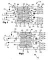
- the dual-fuel fuel injection system 10 includes a fuel injection metering valve 40 for controlling the pressure of diesel in the common rail 32 such that it is driven to a value that is a predefined function of the petrol pressure in the common rail 20.
- the metering valve 40 is arranged to control the pressures such that the diesel pressure is substantially the same as the petrol pressure (i.e. the metering valve is arranged to maintain substantially the same fuel pressure in the two sides of the injection system).
- the metering valve 40 comprises a valve body 42 having a first inlet port indicated at 44 for receiving petrol from the petrol reservoir 12 and a second inlet port indicated at 46 for receiving diesel from the diesel reservoir 14.
- the valve body 42 contains valving depicted in the form of a floating spool 48 housed in a bore 50.
- Respective fuel inlet passages 52, 54 extend from the first inlet port 44 and second inlet port 46 to the bore 50.
- Respective fuel outlet passages 56, 58 extend from the bore 50 to a first outlet port indicated at 60 and a second outlet port indicated at 62.
- the petrol and diesel flows across the bore 50 from the fuel inlet passages 52, 54 to the fuel outlet passages 56, 58 are controlled according to the position of the spool 48 in the bore 50.
- the arrangement of the spool 48 and bore 50 in the fuel flow path between the inlet passages 52, 54 and the respective fuel outlet passages 56, 58 may thus be considered to comprise first and second metering ports for the first and second fuels
- a take off line 64 from the petrol return line 26 feeds petrol into a first flow path 66 in the valve body 42.
- the first flow path 66 leads into a first chamber 68 defined at one end of the bore 50 between the bore wall and an end surface 70 of the spool 48.
- a fuel flow regulator for example, in the form of a damping orifice 71 is placed in the take off line 64.
- a take off line 72 from the diesel return line 36 feeds diesel into a second flow path 74 in the valve body 42.
- the second flow path 74 leads into a second chamber 76 defined at the opposite end of the bore 50 between the bore wall and an end surface 78 of the spool 48.
- the respective surface areas of the end surfaces 70, 78 of the spool 48 are substantially equal so that the spool will act to try and equalise the fuel pressures in the common rails 20, 32.
- Figure 1 shows the position of the spool 48 when the fuel pressures in the common rails 20, 32 are matched.
- the pressures in the chambers 68, 76 will be approximately matched and because the respective surface areas of the end surfaces 70, 78 are substantially equal and the spool is otherwise free to move in the bore 50, there is no net force on the spool. Therefore, the spool 48 occupies a neutral position at which it allows fuel to flow evenly across the bore 50 from the inlet passages 52, 54, through the respective outlet passages 56, 58 to each of the fuel pumps 16, 30.
- Figure 2 shows the position of the spool 48 when the pressure in the second common rail 32 exceeds the pressure in the first common rail 20.
- This pressure imbalance could, for example, be caused by opening the pressure regulator 28 and/or restricting the inlet metering valve 18.
- the pressure in the second chamber 76 will be higher than the pressure in the first chamber 68 and so the spool will move axially in the bore 50 in the direction of the first chamber 68.
- This movement causes a land 80 of the spool 48 to restrict the flow of diesel from the fuel inlet passage 54 to the fuel outlet passage 58 and a land 82 to move to a position that opens up the flow path through the bore 50 between the fuel inlet passage 52 and the fuel outlet passage 56 so that the pressure in the common rail 20 is able to increase, while the pressure in the common rail 32 is held steady, or allowed to decay as a result of the injection of diesel from the fuel injectors 34.
- the spool 48 may be provided with one or more radial through bores to define flow paths from respective inlet passages 52, 54 and outlet passages 56, 58.
- Figure 3 shows the position of the spool 48 when the pressure in the common rail 32 is lower than in the common rail 20.
- This pressure imbalance could, for example be caused by closing the pressure regulator 28 and/or opening the inlet metering valve 18.
- the pressure in the second chamber 76 will be lower than the pressure in the first chamber 68 and so the spool 48 will move axially in the bore 50 in the direction of the second chamber 76.
- the metering valve 40 controls the petrol and diesel pressures in two distinct injection sub-systems within the dual-fuel fuel injection system 10 such that the diesel pressure in the second system tracks the petrol pressure in the first system as the metering valve seeks to maintain a pressure balance between the two injection systems.
- a single electronic controller (not shown) inlet metering valve 18 and pressure regulator 28 can be used to control the fuel pressure in the two systems, thus reducing the number of components needed to control the fuel pressures in a dual-fuel fuel injection system.
- the pressure of the petrol in the common rail 20 is controlled by the inlet metering valve 18 and pressure regulator 28 under the control of an electronic controller (not shown) and the fuel injection metering valve 40 operates to cause the pressure of the diesel in the common rail 32 to follow the pressure of the petrol.
- the inlet metering valve 18 and pressure regulator 28 and associated electronic control unit (ECU) simultaneously control the injection pressure of the diesel and petrol in the respective common rails.
- the dual-fuel fuel injection system 10 illustrated there are respective sets of fuel injectors 22, 34 for each of the two fuels.
- the injectors 22 were designed so as to be able to selectively inject two different fuels, the set of injectors 34 could be dispensed with and the common rail 32 could be arranged to supply the set of injectors 22 (not shown), thereby further simplifying the dual-fuel fuel injection system 10.
- the common rail 20 and common rail 32 would both be fluidly connected to that set of injectors, for example, via fuel flow pipes.
- each "set" of injectors may comprise any desirable number of individual injectors, such as 2, 4, 6, 8, 12, 16 and so on.
- the fuel injection metering valve 40 has been described as operating with two different fuels, with the metering valve controlling the pressure of the two fuels in the respective common rails 20, 32 such that the pressure of one fuel in its common rail tracks that of the other.
- the metering valve is particularly applicable to allowing different fuels to be used in one fuel delivery system, it may also be used for controlling differentially the fuel pressure in each rail of a twin-rail system that uses just one fuel type. This would make it possible to use a common rail system that has capacity for a four or six cylinder engine on an eight of twelve cylinder engine by simply using a pair of the rails with the fuel pressure in the second rail being kept equal to the pressure in the first by operation of the metering valve 40.
- such an arrangement may be useful where it is more economical or efficient to use two smaller fuel pumps (or a dual-fuel pump) instead of one larger fuel pump.
- Such an arrangement is particularly beneficial where it is desirable to have a choice of rail pressures to inject from (even with just one fuel type), so that different injections in a firing cycle can be injected at different pressures in order to give an extra degree of freedom to optimise engine emissions.
- the metering valve may suitably be configured such that the pressure in the second common rail tracked that in the first, but such that there was a predetermined difference between the two output pressures.
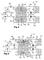
- Figure 4 shows two modifications to the metering valve 40. Otherwise all components of the fuel injection system are as shown in Figures 1 to 3 .
- the first modification shown in Figure 4 is the inclusion of a biasing member suitably in the form of a coil spring 90 disposed in the chamber 68.
- the spring 90 is located around a guidepost 92 that extends coaxially from the end surface 70 of the spool 48 and acts between the end surface 70 and the opposed end wall of the bore 50.
- the second modification shown in Figure 4 is the provision of a vent valve 94, 96 in the form of a needle 94 provided in a passage 96 extending from the chamber 76 and exposed to a relatively low pressure region of the fuel injection system 10.
- the low pressure region with which the passage 96 communicates is the fuel reservoir 14.
- the vent valve 94, 96 opens when the fuel pressure in the chamber 76 exceeds the fuel pressure in the chamber 68 to allow the fuel pressure in the common rail 32 to collapse (quickly) in the same way as the pressure would collapse quickly in the common rail 20 if the pressure regulator 28 were opened.
- the effect of the spring 90 is to provide a difference in the fuel supply (or flow rate) between the respective outputs from the first and second outlet ports to the common rails 20, 32.
- the amount of the fuel supply difference is determined by the strength of the spring, since in order for the spool 48 to be moved from the neutral position indicated in Figure 1 , the fuel pressure in the chamber 76 will have to be greater than the fuel pressure in the chamber 68 by an amount sufficient to overcome the spring force.
- the biasing member may be arranged within the chamber 76, such that the spool 48 is generally biased towards the chamber 68.
- one spring would have to be stronger than the other.
- springs at both ends of the spool 48 in order to make it respond more quickly to changes of the fuel pressure in the chambers 68, 76.
- the vent valve 94, 96 When the vent valve 94, 96 is used in combination with a biasing member such as the spring 90 as shown in Figure 4 , the vent valve will only open when the fuel pressure in the chamber 76 exceeds the fuel pressure in the chamber 68 by an amount determined by the spring rate (or force).
- the needle 94 is free to enter the passage 96, so allowing the spool 48 to provide the initial response to changes of pressure, such that most of the control can be performed by the more efficient metering provided by movement of the spool 48 in the bore 50 and the loss of high pressure fuel inherent in opening the vent valve 94, 96 is kept to a minimum.
- Figure 5 shows an alternative embodiment of the vent valve 94, 96 in which the spool 48 of the metering valve 40 is provided with a vent valve that is biased against a valve seat 98. Otherwise all components of the metering valve are as shown in Figure 4 .
- the effect of having the vent valve 94, 96 biased against the valve seat 98 is that the metering valve 40 only comes into effect if the fuel pressure in the common rail 32 exceeds the fuel pressure in the common rail 20 by a predetermined threshold value. This mechanism may improve pressure stability in the common rail 20 at the expense of larger pressure errors in the common rail 32.
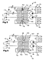
- Figure 6 shows the spool 48 of the fuel injection metering valve 40 provided with a piston 100 that is housed in a cylindrical bore 102. Otherwise all components of the fuel injection system are as shown in Figures 1 to 3
- the piston 100 extends coaxially from the end surface 78 of the spool 48 into the cylindrical bore 102, which leads from the chamber 76 to a relatively low-pressure area of the fuel injection system 10; for example, to the fuel reservoir 14.
- An effect of the piston 100 is to reduce the area of the end surface 70 that is exposed to the fuel pressure in the chamber 76 so that the fuel pressure in the common rail 32 will follow the fuel pressure in the common rail 20, but with a difference between the two that is defined by the diameter of the piston 100. It will be appreciated that the same effect can be obtained by providing different diameter pistons at the two ends of the spool 48, or making one land 80, 82 of the spool 48 and the respective mating portion of the bore 50 smaller in diameter than the other.
- the piston 100 and cylindrical bore 102 may alternatively be provided at the opposite end of the spool 48, i.e. at the chamber 68 end of the spool.
- Figure 7 shows a modification to the metering valve 40 shown in Figure 5 . Otherwise all components of the fuel injection system are as shown in Figures 1 to 3 already described.
- the (spring) biasing arrangement (of Figure 5 ) acting on the end of the spool 48 in the chamber 68 has been replaced by a piston arrangement 100, 102 essentially corresponding to that shown in Figure 6 .
- this provides the designer with the freedom to alter the pressure ratio between the common rail 20 and the common rail 32, by varying the diameter of the piston and/or the pressure to which the end face 110 of the piston 100 is exposed and the diameters of the needle 94 and passage 96, whilst retaining the function of the vent valve 94, 96.
- a further modification would be to provide an actuator 112 (not shown) to act on the piston 100.
- Any suitable actuator may be used, such as a solenoid or a piezo-electric device.
- the provision of an actuator would allow for additional control functions under the control of an electronic controller (not shown).
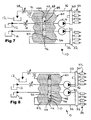
- Figure 8 shows a modification to the metering valve 40 shown in Figure 4 . Otherwise all components of the fuel injection system are as shown in Figures 1 to 3 .
- the passage 96 is substituted by a passage 108 defined by a floating component in the form of a sleeve 110.
- the sleeve 110 is located in the chamber 76 and is free to move radially with respect to the spool axis so that it can align itself with the needle 94.
- an oversize bore 112 is provided in the body 42 to connect the passage 108 defined by the sleeve 110 with a low pressure region of the fuel injection system 10.
- the floating component e.g. sleeve 110
- the floating component could be provided at one or both ends of the bore 50 of the metering valve 40.
- a floating sleeve similar to the sleeve 110 could be used to define the vent valve seat 98 in Figure 5 .
- Figure 9 shows the fuel injection metering valve 40 incorporated in a single fuel pump 120.
- the pump receives the respective outputs from the fuel outlet passages 56, 58 of the valve body 42 and outputs respective fuel flows to the common rails (not shown) via respective outlets 122, 124.
- the fuel pump 120 can pump two different fuels or pump separate flows of the same fuel.
- the provision of an integral pump and metering valve can provide advantages in terms of economy of space and weight and reduces the number of component to component connections to be made. It should be appreciated that as an alternative to integrating the metering valve 40 and pump 120, the pump 120 may simply be substituted for the fuel pumps 16, 30 in any of the illustrated fuel injection systems. Accordingly, the fuel delivery systems and fuel injection systems of the invention may comprise a fuel pump that is capable of pumping two different fuels, or pumping separate flows of the same fuel.
Landscapes
- Engineering & Computer Science (AREA)
- Chemical & Material Sciences (AREA)
- Combustion & Propulsion (AREA)
- Mechanical Engineering (AREA)
- General Engineering & Computer Science (AREA)
- Fuel-Injection Apparatus (AREA)
Claims (24)
- Soupape de dosage d'injection de carburant (40) ayant une première sortie de carburant (60) pour fournir du carburant à un premier volume accumulateur (20), une seconde sortie de carburant (62) pour fournir du carburant à un second volume accumulateur (32), un système de valves (48) pour commander l'écoulement de carburant vers ladite première et ladite seconde sortie de carburant, un premier trajet d'écoulement (66, 68) pour exposer ledit système de valves à une pression de carburant représentative d'une pression du carburant dans ledit premier volume accumulateur et un second trajet d'écoulement (74, 76) pour exposer ledit système de valves à une pression de carburant représentative de la pression du carburant dans ledit second volume accumulateur, lesdites valves (48) réagissant auxdites pressions de carburant représentatives pour commander la fourniture de carburant depuis ladite seconde sortie de carburant (62) vers ledit second volume accumulateur en tant que fonction de la pression du carburant dans ledit premier volume accumulateur.
- Soupape de dosage d'injection de carburant (40) selon la revendication 1, comprenant au moins un élément de sollicitation (90) agissant sur ledit système de valves (48) de telle façon que, en utilisation, il existe une différence de pression de carburant entre ledit premier volume accumulateur et ledit second volume accumulateur qui est au moins en partie déterminée par ledit au moins un élément de sollicitation.
- Soupape de dosage d'injection de carburant (40) selon la revendication 1 ou 2, dans laquelle ledit système de valves comprend un élément de valve (48) qui est capable de coulisser axialement dans des directions opposées respectives en réponse auxdites pressions de carburant représentatives, ledit élément de valve étant doté d'une projection (94) qui est reçue en coulissement dans un passage (108) défini par un élément (110) qui est capable de se déplacer radialement par rapport à l'axe de l'élément de valve.
- Soupape de dosage d'injection de carburant (40) selon l'une quelconque des revendications précédentes, dans laquelle ledit système de valves (48) comprend des portions de réception de pression respectives (70, 78) exposées à ladite première et à ladite seconde pression de carburant représentatives, et est doté d'au moins une projection (94, 100) qui est exposée à une pression différente pour au moins partiellement déterminer une différence de pression entre ledit premier volume accumulateur et ledit second volume accumulateur.
- Soupape de dosage d'injection de carburant (40) selon l'une quelconque des revendications précédentes, dans laquelle ledit système de valves (48) est pourvu d'une projection (94) qui est capable de coulisser axialement dans un passage (96, 108) et agencé pour purger un trajet parmi ledit premier trajet d'écoulement (66, 68) et ledit second trajet d'écoulement (74, 76) via ledit passage.
- Soupape de dosage d'injection de carburant (40) selon la revendication 5, dans laquelle la projection est sollicitée en engagement avec un siège de soupape (98).
- Soupape de dosage d'injection de carburant (40) selon la revendication 1, dans laquelle ledit système de valves (48) comprend des portions de réception de pression (70, 78) respectives exposées à ladite première et à ladite seconde pression de carburant représentatives, et agencées de telle façon que la pression du carburant dans ledit second volume accumulateur est commandée pour être sensiblement égale à la pression du carburant dans ledit premier volume accumulateur.
- Soupape de dosage d'injection de carburant (40) selon l'une quelconque des revendications précédentes, dans laquelle, pour réduire la pression dans un volume parmi ledit premier ou ledit second volume accumulateur (20 ; 32), la soupape de dosage agit pour diminuer la fourniture de carburant depuis ladite première ou ladite seconde sortie de carburant (60 ; 62) respectivement ; et pour augmenter la pression dans un volume parmi ledit premier ou ledit second volume accumulateur, la soupape de dosage agit pour augmenter la fourniture de carburant depuis ladite première ou ladite seconde sortie de carburant respectivement.
- Soupape de dosage d'injection de carburant (40) selon l'une quelconque des revendications précédentes, dans laquelle le premier et le second volume accumulateur (20 ; 32) sont un premier et un second distributeur du type "common rail".
- Pompe à carburant (120) ayant une soupape de dosage d'injection de carburant intégrée (40) selon l'une quelconque des revendications précédentes, ladite pompe comprenant des moyens de pompage pour pomper et refouler séparément des flux de carburant respectifs reçus depuis ladite première et ladite seconde sortie de carburant (60, 62).
- Système d'injection de carburant (10) comprenant une soupape de dosage d'injection de carburant (40) configurée, en utilisation, pour fournir une première sortie de carburant et une seconde sortie de carburant vers un premier volume accumulateur (20) et un second volume accumulateur (32), respectivement, et comprenant un système de valves (48) en communication fluidique avec des trajets d'écoulement respectifs (66, 68 ; 74, 76) qui, en utilisation, expose des portions de réception de pression respectives (70 ; 78) du système de valves à des écoulements de pression de carburant respectifs indicatifs des pressions du carburant dans ledit premier et ledit second volume accumulateur ; ledit système de valves réagissant auxdits écoulements de pression pour amener la pression du carburant dans ledit second volume accumulateur à suivre la pression du carburant dans le premier volume accumulateur.
- Système d'injection de carburant selon la revendication 11, dans lequel ledit système de valves (48) est associé à au moins un dispositif (90, 94, 100) qui amène la pression du carburant dans ledit second volume accumulateur à être différente de la pression du carburant dans ledit premier volume accumulateur à raison d'une quantité prédéterminée.
- Système d'injection de carburant selon la revendication 12, dans lequel ledit au moins un dispositif (90, 94, 100) comprend au moins un élément parmi un élément de sollicitation (90) agissant sur ledit système de valves, et un élément (94, 100) relié audit système de valves et exposé à une pression relativement basse pour modifier l'effet de l'exposition dudit système de valves à au moins un desdits écoulements de pression indicatifs de la pression du carburant dans ledit premier et ledit second volume accumulateur.
- Système d'injection de carburant selon la revendication 12 ou 13, dans lequel ledit au moins un dispositif (90, 94, 100) comprend un élément (94, 100) relié au système de valves et exposé à une pression relativement basse, ledit élément (94, 100) se projetant depuis ledit système de valves (48) dans un passage (108) d'un élément de définition de passage (110) et étant capable de coulisser axialement dans ledit passage, ledit élément de définition de passage étant libre de se déplacer radialement par rapport à l'axe de coulissement.
- Système d'injection de carburant selon l'une quelconque des revendications 11 à 14, comprenant un dispositif de purge (94) pour purger la pression depuis le trajet d'écoulement (74, 76) qui expose le système de valves à l'écoulement de pression indicatif de la pression du carburant dans ledit second volume accumulateur.
- Système d'injection de carburant selon l'une quelconque des revendications 11 à 15, comprenant au moins une soupape (18, 28) disposée en amont ou en aval de ladite soupape de dosage d'injection de carburant (40) et dont la fonction est de recevoir des ordres pour ajuster la pression du carburant dans ledit trajet d'écoulement (66, 68).
- Système d'injection de carburant selon l'une quelconque des revendications 11 à 16, comprenant une pompe à carburant (120) pour recevoir ladite première et ladite seconde sortie de carburant et pomper sélectivement lesdites sorties vers le premier et le second volume accumulateur respectif.
- Système d'injection de carburant selon l'une quelconque des revendications 11 à 17, comprenant en outre au moins un premier groupe d'injecteurs de carburant (22) pour recevoir du carburant depuis ledit premier et ledit second volume accumulateur (20 ; 32).
- Système d'injection de carburant selon la revendication 18, comprenant un premier groupe d'injecteurs de carburant (22) pour recevoir du carburant depuis ledit premier volume accumulateur (20) et un second groupe d'injecteurs de carburant (34) pour recevoir du carburant depuis ledit second volume accumulateur (32).
- Système d'injection de carburant (selon l'une quelconque des revendications 11 à 19, dans lequel le premier et le second volume accumulateur (20 ; 32) sont un premier et un second distributeur du type "common rail".
- Système de distribution de carburant comprenant un système d'injection de carburant selon l'une quelconque des revendications 11 à 20 et des réservoirs de carburant respectifs (12 ; 14) reliés à ladite soupape de dosage d'injection de carburant (40) pour fournir le carburant pour ladite première et ladite seconde sortie de carburant.
- Procédé pour commander la pression du carburant dans un système d'injection de carburant, ledit procédé comprenant de pomper un premier carburant depuis un réservoir de carburant (12) vers un premier volume accumulateur (20), de pomper un second carburant depuis un second réservoir de carburant (14) vers un second volume accumulateur (32), de fixer une pression de fourniture pour ledit premier carburant depuis ledit premier volume accumulateur, d'exposer un élément de soupape (48) à une source (64, 66) dudit premier carburant qui est à une pression indicative de ladite pression de distribution, et d'exposer ledit élément de soupape à une source (72, 74) dudit second carburant à une pression indicative d'une pression de distribution dudit second carburant ; ledit élément de soupape ayant pour fonction de réagir aux pressions respectives indicatives de la pression de distribution pour amener la pression de distribution dudit second carburant à être sensiblement maintenue en relation fixe à la pression de distribution dudit premier carburant.
- Procédé selon la revendication 22, dans lequel ledit élément de soupape (48) est mobile dans des directions opposées respectives par exposition audit premier et audit second carburant depuis lesdites sources respectives (64, 66 ; 72, 74).
- Procédé selon la revendication 22 ou 23, dans lequel ledit premier et ledit second carburant sont des carburants différents.
Priority Applications (6)
| Application Number | Priority Date | Filing Date | Title |
|---|---|---|---|
| DE200760012893 DE602007012893D1 (de) | 2007-11-05 | 2007-11-05 | Dosierventile für die Kraftstoffeinspritzung |
| EP20070254369 EP2055925B1 (fr) | 2007-11-05 | 2007-11-05 | Soupapes de dosage d'injection de carburant |
| AT07254369T ATE500415T1 (de) | 2007-11-05 | 2007-11-05 | Dosierventile für die kraftstoffeinspritzung |
| US12/283,044 US7757662B2 (en) | 2007-11-05 | 2008-09-09 | Fuel injection metering valves |
| JP2008275036A JP4991672B2 (ja) | 2007-11-05 | 2008-10-27 | 燃料噴射計量バルブ |
| CN2008101744117A CN101429909B (zh) | 2007-11-05 | 2008-11-05 | 燃料喷射计量阀 |
Applications Claiming Priority (1)
| Application Number | Priority Date | Filing Date | Title |
|---|---|---|---|
| EP20070254369 EP2055925B1 (fr) | 2007-11-05 | 2007-11-05 | Soupapes de dosage d'injection de carburant |
Publications (2)
| Publication Number | Publication Date |
|---|---|
| EP2055925A1 EP2055925A1 (fr) | 2009-05-06 |
| EP2055925B1 true EP2055925B1 (fr) | 2011-03-02 |
Family
ID=39232063
Family Applications (1)
| Application Number | Title | Priority Date | Filing Date |
|---|---|---|---|
| EP20070254369 Not-in-force EP2055925B1 (fr) | 2007-11-05 | 2007-11-05 | Soupapes de dosage d'injection de carburant |
Country Status (6)
| Country | Link |
|---|---|
| US (1) | US7757662B2 (fr) |
| EP (1) | EP2055925B1 (fr) |
| JP (1) | JP4991672B2 (fr) |
| CN (1) | CN101429909B (fr) |
| AT (1) | ATE500415T1 (fr) |
| DE (1) | DE602007012893D1 (fr) |
Families Citing this family (22)
| Publication number | Priority date | Publication date | Assignee | Title |
|---|---|---|---|---|
| US7861684B2 (en) * | 2009-05-14 | 2011-01-04 | Advanced Diesel Concepts Llc | Compression ignition engine and method for controlling same |
| US8807115B2 (en) | 2009-05-14 | 2014-08-19 | Advanced Diesel Concepts, Llc | Compression ignition engine and method for controlling same |
| US20110232601A1 (en) * | 2010-03-25 | 2011-09-29 | Caterpillar Inc. | Compression ignition engine with blended fuel injection |
| US8622046B2 (en) * | 2010-06-25 | 2014-01-07 | Caterpillar Inc. | Fuel system having accumulators and flow limiters |
| CN102797593A (zh) * | 2011-05-25 | 2012-11-28 | 广西玉柴机器股份有限公司 | 一种燃气喷射装置 |
| DE102011080346A1 (de) * | 2011-08-03 | 2013-02-07 | Robert Bosch Gmbh | Einspritzvorrichtung, Brennkraftmaschine und Verfahren zum Betrieb einer Brennkraftmaschine |
| US8499542B2 (en) * | 2011-08-17 | 2013-08-06 | Hamilton Sundstrand Corporation | Flow balancing valve |
| US8789513B2 (en) | 2011-09-26 | 2014-07-29 | Hitachi, Ltd | Fuel delivery system |
| US9222388B2 (en) | 2013-02-28 | 2015-12-29 | Tenneco Automotive Operating Company Inc. | Urea common rail |
| US9234488B2 (en) * | 2013-03-07 | 2016-01-12 | Caterpillar Inc. | Quill connector for fuel system and method |
| US9518518B2 (en) | 2013-04-19 | 2016-12-13 | Caterpillar Inc. | Dual fuel common rail transient pressure control and engine using same |
| DE102013220607B4 (de) * | 2013-10-11 | 2017-01-05 | Continental Automotive Gmbh | Vorrichtung und Verfahren zur Reduzierung von Varianten bei Kraftstoffpumpen-Elektroniken |
| CN103590925B (zh) * | 2013-11-27 | 2016-07-13 | 哈尔滨市展鸿化工产品销售有限公司 | 汽车双电脑、双储油箱、双燃油分配器、双喷射电喷系统 |
| DE102014010717A1 (de) * | 2014-07-19 | 2016-01-21 | L'orange Gmbh | Dual-Fuel-Kraftstoffinjektor |
| CN104879640A (zh) * | 2015-04-20 | 2015-09-02 | 徐存然 | 一种机械热烫粘合机装配润滑器 |
| US10184427B2 (en) * | 2015-08-11 | 2019-01-22 | Volvo Truck Corporation | Vehicle comprising a pressurized liquid fuel system and method for operating a pressurized liquid fuel system |
| US20170298887A1 (en) * | 2016-04-13 | 2017-10-19 | Cummins Inc. | Systems and methods for controlling fuel injection into a plurality of fuel rails |
| KR102406158B1 (ko) * | 2016-04-14 | 2022-06-07 | 현대자동차주식회사 | 디젤 차량의 연료공급장치 |
| CN107061054A (zh) * | 2017-06-02 | 2017-08-18 | 广西玉柴机器股份有限公司 | 气体发动机的燃气供气装置 |
| GB201815839D0 (en) * | 2018-09-28 | 2018-11-14 | Rolls Royce Plc | Fuel spray nozzle |
| DE102018220566A1 (de) * | 2018-11-29 | 2020-06-04 | Robert Bosch Gmbh | Kraftstofffördereinrichtung für eine Brennkraftmaschine und ein Verfahren zur Regelung des Druckes in einer Kraftstofffördereinrichtung |
| US20230383715A1 (en) * | 2022-05-27 | 2023-11-30 | Hamilton Sundstrand Corporation | Dual valve fuel metering systems |
Family Cites Families (27)
| Publication number | Priority date | Publication date | Assignee | Title |
|---|---|---|---|---|
| AU1891467A (en) * | 1967-03-14 | 1968-09-19 | Caterpillar Tractor Co | Engine fuel system |
| US4043198A (en) * | 1976-01-14 | 1977-08-23 | Stillwell Logan W | Positive displacement fluid flowmeter |
| JPS54155319A (en) * | 1978-05-29 | 1979-12-07 | Komatsu Ltd | Fuel injection controller for internal combustion engine |
| US4509548A (en) * | 1982-07-01 | 1985-04-09 | The United States Of America As Represented By The Administrator Of The National Aeronautics And Space Administration | Reactant pressure differential control for fuel cell gases |
| US4752211A (en) * | 1986-09-12 | 1988-06-21 | Sabin Darrel B | Flow proportioning system |
| US4971016A (en) * | 1988-09-23 | 1990-11-20 | Cummins Engine Company, Inc. | Electronic controlled fuel supply system for high pressure injector |
| US5024195A (en) * | 1990-06-07 | 1991-06-18 | Pien Pao C | Multi-fuel compression-ignition engine and fuel injection pump therefor |
| US5277162A (en) * | 1993-01-22 | 1994-01-11 | Cummins Engine Company, Inc. | Infinitely variable hydromechanical timing control |
| US5423301A (en) * | 1994-02-17 | 1995-06-13 | Cummins Engine Company, Inc. | Timing control valve for hydromechanical fuel system |
| GB9422864D0 (en) * | 1994-11-12 | 1995-01-04 | Lucas Ind Plc | Fuel system |
| US5701869A (en) * | 1996-12-13 | 1997-12-30 | Ford Motor Company | Fuel delivery system |
| DE19727413A1 (de) * | 1997-06-27 | 1999-01-07 | Bosch Gmbh Robert | Kraftstoffeinspritzsystem für Brennkraftmaschinen |
| US5960809A (en) * | 1997-08-13 | 1999-10-05 | R.D.K. Corporation | Fuel equalizing system for plurality of fuel tanks |
| EP1008741B1 (fr) * | 1998-11-20 | 2003-04-02 | Mitsubishi Jidosha Kogyo Kabushiki Kaisha | Système d'injection de combustible du type à accumulateur |
| GB0004949D0 (en) * | 2000-03-02 | 2000-04-19 | Needham David M | Fluid flow proportioning device |
| WO2002014686A1 (fr) * | 2000-08-14 | 2002-02-21 | Stanadyne Automotive Corp. | Commutateur autoregule pour systeme d'alimentation en carburant par rampes d'injection divisees |
| JP2002089401A (ja) * | 2000-09-18 | 2002-03-27 | Hitachi Ltd | 燃料供給装置 |
| US6601565B2 (en) * | 2000-10-30 | 2003-08-05 | Siemens Automotive Inc. | Pressure regulating valve and system |
| JP4240835B2 (ja) * | 2001-03-29 | 2009-03-18 | 株式会社日本自動車部品総合研究所 | 内燃機関の燃料噴射装置 |
| US6742503B2 (en) * | 2002-09-18 | 2004-06-01 | Caterpillar Inc. | Dual pressure fluid system and method of use |
| JP4123969B2 (ja) * | 2003-02-20 | 2008-07-23 | トヨタ自動車株式会社 | 内燃機関の燃料噴射装置 |
| GB2414517B (en) | 2003-03-04 | 2006-08-02 | Bosch Gmbh Robert | Fuel injection system with accumulator fill valve assembly |
| JP2005163556A (ja) * | 2003-11-28 | 2005-06-23 | Denso Corp | コモンレール式燃料噴射装置 |
| JP4239958B2 (ja) * | 2004-12-06 | 2009-03-18 | トヨタ自動車株式会社 | 内燃機関の燃料噴射装置の故障診断方法および内燃機関の燃料噴射装置 |
| JP2006336593A (ja) * | 2005-06-06 | 2006-12-14 | Nissan Motor Co Ltd | 筒内直噴内燃機関の始動制御装置及び始動制御方法 |
| DE102005053095B3 (de) * | 2005-11-04 | 2007-01-18 | Alexander Sellentin | Kraftstoffzuführungseinrichtung für einen Dieselmotor und Verfahren zum Betreiben einer Kraftstoffzuführungseinrichtung für einen Dieselmotor |
| JP4297160B2 (ja) * | 2006-12-22 | 2009-07-15 | トヨタ自動車株式会社 | 内燃機関 |
-
2007
- 2007-11-05 AT AT07254369T patent/ATE500415T1/de active
- 2007-11-05 EP EP20070254369 patent/EP2055925B1/fr not_active Not-in-force
- 2007-11-05 DE DE200760012893 patent/DE602007012893D1/de active Active
-
2008
- 2008-09-09 US US12/283,044 patent/US7757662B2/en not_active Expired - Fee Related
- 2008-10-27 JP JP2008275036A patent/JP4991672B2/ja not_active Expired - Fee Related
- 2008-11-05 CN CN2008101744117A patent/CN101429909B/zh not_active Expired - Fee Related
Also Published As
| Publication number | Publication date |
|---|---|
| CN101429909A (zh) | 2009-05-13 |
| DE602007012893D1 (de) | 2011-04-14 |
| ATE500415T1 (de) | 2011-03-15 |
| CN101429909B (zh) | 2011-03-23 |
| JP4991672B2 (ja) | 2012-08-01 |
| EP2055925A1 (fr) | 2009-05-06 |
| US20090114193A1 (en) | 2009-05-07 |
| US7757662B2 (en) | 2010-07-20 |
| JP2009115082A (ja) | 2009-05-28 |
Similar Documents
| Publication | Publication Date | Title |
|---|---|---|
| EP2055925B1 (fr) | Soupapes de dosage d'injection de carburant | |
| US6668801B2 (en) | Suction controlled pump for HEUI systems | |
| US11053866B2 (en) | Hydraulically actuated gaseous fuel injector | |
| US5711277A (en) | Accumulating fuel injection apparatus | |
| CA2405167C (fr) | Appareil et procede d'etancheite fluidique permettant de commander dynamiquement la pression du fluide d'etancheite | |
| US5511528A (en) | Accumulator type of fuel injection device | |
| EP0262539A1 (fr) | Soupape d'injection de combustible | |
| US6116273A (en) | Fuel metering check valve arrangement for a time-pressure controlled unit fuel injector | |
| US9316190B2 (en) | High-pressure fuel injection valve for an internal combustion engine | |
| US20070272213A1 (en) | Multi-source fuel system having closed loop pressure control | |
| US10612503B2 (en) | Dual-fuel injector | |
| US20110232601A1 (en) | Compression ignition engine with blended fuel injection | |
| US8215287B2 (en) | Fuel supply apparatus for engine and injector for the same | |
| US6227167B1 (en) | Suction controlled pump for HEUI systems | |
| US6672285B2 (en) | Suction controlled pump for HEUI systems | |
| WO2007100471A1 (fr) | Injecteur de carburant ayant un élément de gicleur avec une rainure annulaire | |
| EP2971709A1 (fr) | Prévention de la défaillance de régulation de carburant | |
| JPH08261112A (ja) | 燃料インジェクター用分流器 | |
| US7392791B2 (en) | Multi-source fuel system for variable pressure injection | |
| JP5494453B2 (ja) | 燃料噴射装置 | |
| JP3877295B2 (ja) | 蓄圧式分配型燃料噴射ポンプ | |
| KR102034334B1 (ko) | 연료 주입 배열체 | |
| US11773792B1 (en) | Multi-fuel injection system and injector | |
| CN111058983B (zh) | 燃料喷射器 | |
| WO2009127868A1 (fr) | Injecteur de carburant |
Legal Events
| Date | Code | Title | Description |
|---|---|---|---|
| PUAI | Public reference made under article 153(3) epc to a published international application that has entered the european phase |
Free format text: ORIGINAL CODE: 0009012 |
|
| AK | Designated contracting states |
Kind code of ref document: A1 Designated state(s): AT BE BG CH CY CZ DE DK EE ES FI FR GB GR HU IE IS IT LI LT LU LV MC MT NL PL PT RO SE SI SK TR |
|
| AX | Request for extension of the european patent |
Extension state: AL BA HR MK RS |
|
| 17P | Request for examination filed |
Effective date: 20091106 |
|
| AKX | Designation fees paid |
Designated state(s): AT BE BG CH CY CZ DE DK EE ES FI FR GB GR HU IE IS IT LI LT LU LV MC MT NL PL PT RO SE SI SK TR |
|
| 17Q | First examination report despatched |
Effective date: 20100126 |
|
| RAP1 | Party data changed (applicant data changed or rights of an application transferred) |
Owner name: DELPHI TECHNOLOGIES HOLDING S.A.R.L. |
|
| GRAP | Despatch of communication of intention to grant a patent |
Free format text: ORIGINAL CODE: EPIDOSNIGR1 |
|
| GRAA | (expected) grant |
Free format text: ORIGINAL CODE: 0009210 |
|
| GRAS | Grant fee paid |
Free format text: ORIGINAL CODE: EPIDOSNIGR3 |
|
| AK | Designated contracting states |
Kind code of ref document: B1 Designated state(s): AT BE BG CH CY CZ DE DK EE ES FI FR GB GR HU IE IS IT LI LT LU LV MC MT NL PL PT RO SE SI SK TR |
|
| REG | Reference to a national code |
Ref country code: GB Ref legal event code: FG4D |
|
| REG | Reference to a national code |
Ref country code: CH Ref legal event code: EP |
|
| REG | Reference to a national code |
Ref country code: IE Ref legal event code: FG4D |
|
| REF | Corresponds to: |
Ref document number: 602007012893 Country of ref document: DE Date of ref document: 20110414 Kind code of ref document: P |
|
| REG | Reference to a national code |
Ref country code: DE Ref legal event code: R096 Ref document number: 602007012893 Country of ref document: DE Effective date: 20110414 |
|
| REG | Reference to a national code |
Ref country code: NL Ref legal event code: VDEP Effective date: 20110302 |
|
| PG25 | Lapsed in a contracting state [announced via postgrant information from national office to epo] |
Ref country code: ES Free format text: LAPSE BECAUSE OF FAILURE TO SUBMIT A TRANSLATION OF THE DESCRIPTION OR TO PAY THE FEE WITHIN THE PRESCRIBED TIME-LIMIT Effective date: 20110613 Ref country code: GR Free format text: LAPSE BECAUSE OF FAILURE TO SUBMIT A TRANSLATION OF THE DESCRIPTION OR TO PAY THE FEE WITHIN THE PRESCRIBED TIME-LIMIT Effective date: 20110603 Ref country code: LT Free format text: LAPSE BECAUSE OF FAILURE TO SUBMIT A TRANSLATION OF THE DESCRIPTION OR TO PAY THE FEE WITHIN THE PRESCRIBED TIME-LIMIT Effective date: 20110302 Ref country code: SE Free format text: LAPSE BECAUSE OF FAILURE TO SUBMIT A TRANSLATION OF THE DESCRIPTION OR TO PAY THE FEE WITHIN THE PRESCRIBED TIME-LIMIT Effective date: 20110302 Ref country code: LV Free format text: LAPSE BECAUSE OF FAILURE TO SUBMIT A TRANSLATION OF THE DESCRIPTION OR TO PAY THE FEE WITHIN THE PRESCRIBED TIME-LIMIT Effective date: 20110302 |
|
| LTIE | Lt: invalidation of european patent or patent extension |
Effective date: 20110302 |
|
| PG25 | Lapsed in a contracting state [announced via postgrant information from national office to epo] |
Ref country code: BG Free format text: LAPSE BECAUSE OF FAILURE TO SUBMIT A TRANSLATION OF THE DESCRIPTION OR TO PAY THE FEE WITHIN THE PRESCRIBED TIME-LIMIT Effective date: 20110602 Ref country code: FI Free format text: LAPSE BECAUSE OF FAILURE TO SUBMIT A TRANSLATION OF THE DESCRIPTION OR TO PAY THE FEE WITHIN THE PRESCRIBED TIME-LIMIT Effective date: 20110302 Ref country code: CY Free format text: LAPSE BECAUSE OF FAILURE TO SUBMIT A TRANSLATION OF THE DESCRIPTION OR TO PAY THE FEE WITHIN THE PRESCRIBED TIME-LIMIT Effective date: 20110302 Ref country code: NL Free format text: LAPSE BECAUSE OF FAILURE TO SUBMIT A TRANSLATION OF THE DESCRIPTION OR TO PAY THE FEE WITHIN THE PRESCRIBED TIME-LIMIT Effective date: 20110302 Ref country code: SI Free format text: LAPSE BECAUSE OF FAILURE TO SUBMIT A TRANSLATION OF THE DESCRIPTION OR TO PAY THE FEE WITHIN THE PRESCRIBED TIME-LIMIT Effective date: 20110302 |
|
| PG25 | Lapsed in a contracting state [announced via postgrant information from national office to epo] |
Ref country code: BE Free format text: LAPSE BECAUSE OF FAILURE TO SUBMIT A TRANSLATION OF THE DESCRIPTION OR TO PAY THE FEE WITHIN THE PRESCRIBED TIME-LIMIT Effective date: 20110302 |
|
| PG25 | Lapsed in a contracting state [announced via postgrant information from national office to epo] |
Ref country code: PT Free format text: LAPSE BECAUSE OF FAILURE TO SUBMIT A TRANSLATION OF THE DESCRIPTION OR TO PAY THE FEE WITHIN THE PRESCRIBED TIME-LIMIT Effective date: 20110704 Ref country code: EE Free format text: LAPSE BECAUSE OF FAILURE TO SUBMIT A TRANSLATION OF THE DESCRIPTION OR TO PAY THE FEE WITHIN THE PRESCRIBED TIME-LIMIT Effective date: 20110302 |
|
| PG25 | Lapsed in a contracting state [announced via postgrant information from national office to epo] |
Ref country code: SK Free format text: LAPSE BECAUSE OF FAILURE TO SUBMIT A TRANSLATION OF THE DESCRIPTION OR TO PAY THE FEE WITHIN THE PRESCRIBED TIME-LIMIT Effective date: 20110302 Ref country code: IS Free format text: LAPSE BECAUSE OF FAILURE TO SUBMIT A TRANSLATION OF THE DESCRIPTION OR TO PAY THE FEE WITHIN THE PRESCRIBED TIME-LIMIT Effective date: 20110702 Ref country code: RO Free format text: LAPSE BECAUSE OF FAILURE TO SUBMIT A TRANSLATION OF THE DESCRIPTION OR TO PAY THE FEE WITHIN THE PRESCRIBED TIME-LIMIT Effective date: 20110302 |
|
| PLBE | No opposition filed within time limit |
Free format text: ORIGINAL CODE: 0009261 |
|
| STAA | Information on the status of an ep patent application or granted ep patent |
Free format text: STATUS: NO OPPOSITION FILED WITHIN TIME LIMIT |
|
| 26N | No opposition filed |
Effective date: 20111205 |
|
| PG25 | Lapsed in a contracting state [announced via postgrant information from national office to epo] |
Ref country code: DK Free format text: LAPSE BECAUSE OF FAILURE TO SUBMIT A TRANSLATION OF THE DESCRIPTION OR TO PAY THE FEE WITHIN THE PRESCRIBED TIME-LIMIT Effective date: 20110302 Ref country code: PL Free format text: LAPSE BECAUSE OF FAILURE TO SUBMIT A TRANSLATION OF THE DESCRIPTION OR TO PAY THE FEE WITHIN THE PRESCRIBED TIME-LIMIT Effective date: 20110302 |
|
| REG | Reference to a national code |
Ref country code: DE Ref legal event code: R097 Ref document number: 602007012893 Country of ref document: DE Effective date: 20111205 |
|
| PG25 | Lapsed in a contracting state [announced via postgrant information from national office to epo] |
Ref country code: MC Free format text: LAPSE BECAUSE OF NON-PAYMENT OF DUE FEES Effective date: 20111130 |
|
| REG | Reference to a national code |
Ref country code: CH Ref legal event code: PL |
|
| GBPC | Gb: european patent ceased through non-payment of renewal fee |
Effective date: 20111105 |
|
| PG25 | Lapsed in a contracting state [announced via postgrant information from national office to epo] |
Ref country code: LI Free format text: LAPSE BECAUSE OF NON-PAYMENT OF DUE FEES Effective date: 20111130 Ref country code: CH Free format text: LAPSE BECAUSE OF NON-PAYMENT OF DUE FEES Effective date: 20111130 |
|
| REG | Reference to a national code |
Ref country code: FR Ref legal event code: ST Effective date: 20120731 |
|
| REG | Reference to a national code |
Ref country code: IE Ref legal event code: MM4A |
|
| PG25 | Lapsed in a contracting state [announced via postgrant information from national office to epo] |
Ref country code: IE Free format text: LAPSE BECAUSE OF NON-PAYMENT OF DUE FEES Effective date: 20111105 Ref country code: GB Free format text: LAPSE BECAUSE OF NON-PAYMENT OF DUE FEES Effective date: 20111105 |
|
| PG25 | Lapsed in a contracting state [announced via postgrant information from national office to epo] |
Ref country code: FR Free format text: LAPSE BECAUSE OF NON-PAYMENT OF DUE FEES Effective date: 20111130 |
|
| PGFP | Annual fee paid to national office [announced via postgrant information from national office to epo] |
Ref country code: CZ Payment date: 20121101 Year of fee payment: 6 Ref country code: DE Payment date: 20121128 Year of fee payment: 6 |
|
| PG25 | Lapsed in a contracting state [announced via postgrant information from national office to epo] |
Ref country code: MT Free format text: LAPSE BECAUSE OF FAILURE TO SUBMIT A TRANSLATION OF THE DESCRIPTION OR TO PAY THE FEE WITHIN THE PRESCRIBED TIME-LIMIT Effective date: 20110302 |
|
| PGFP | Annual fee paid to national office [announced via postgrant information from national office to epo] |
Ref country code: IT Payment date: 20121123 Year of fee payment: 6 |
|
| PGFP | Annual fee paid to national office [announced via postgrant information from national office to epo] |
Ref country code: AT Payment date: 20121019 Year of fee payment: 6 |
|
| PG25 | Lapsed in a contracting state [announced via postgrant information from national office to epo] |
Ref country code: LU Free format text: LAPSE BECAUSE OF NON-PAYMENT OF DUE FEES Effective date: 20111105 |
|
| PG25 | Lapsed in a contracting state [announced via postgrant information from national office to epo] |
Ref country code: TR Free format text: LAPSE BECAUSE OF FAILURE TO SUBMIT A TRANSLATION OF THE DESCRIPTION OR TO PAY THE FEE WITHIN THE PRESCRIBED TIME-LIMIT Effective date: 20110302 |
|
| PG25 | Lapsed in a contracting state [announced via postgrant information from national office to epo] |
Ref country code: HU Free format text: LAPSE BECAUSE OF FAILURE TO SUBMIT A TRANSLATION OF THE DESCRIPTION OR TO PAY THE FEE WITHIN THE PRESCRIBED TIME-LIMIT Effective date: 20110302 |
|
| REG | Reference to a national code |
Ref country code: DE Ref legal event code: R082 Ref document number: 602007012893 Country of ref document: DE Representative=s name: MANITZ, FINSTERWALD & PARTNER GBR, DE Ref country code: AT Ref legal event code: MM01 Ref document number: 500415 Country of ref document: AT Kind code of ref document: T Effective date: 20131105 |
|
| REG | Reference to a national code |
Ref country code: DE Ref legal event code: R082 Ref document number: 602007012893 Country of ref document: DE Representative=s name: MANITZ, FINSTERWALD & PARTNER GBR, DE Effective date: 20140715 Ref country code: DE Ref legal event code: R081 Ref document number: 602007012893 Country of ref document: DE Owner name: DELPHI INTERNATIONAL OPERATIONS LUXEMBOURG S.A, LU Free format text: FORMER OWNER: DELPHI TECHNOLOGIES HOLDING S.A.R.L., BASCHARAGE, LU Effective date: 20140715 |
|
| REG | Reference to a national code |
Ref country code: DE Ref legal event code: R119 Ref document number: 602007012893 Country of ref document: DE Effective date: 20140603 |
|
| PG25 | Lapsed in a contracting state [announced via postgrant information from national office to epo] |
Ref country code: IT Free format text: LAPSE BECAUSE OF NON-PAYMENT OF DUE FEES Effective date: 20131105 Ref country code: AT Free format text: LAPSE BECAUSE OF NON-PAYMENT OF DUE FEES Effective date: 20131105 Ref country code: DE Free format text: LAPSE BECAUSE OF NON-PAYMENT OF DUE FEES Effective date: 20140603 Ref country code: CZ Free format text: LAPSE BECAUSE OF NON-PAYMENT OF DUE FEES Effective date: 20131105 |