EP2052646A1 - Aufhängeelement für ein Bild, einen Spiegel oder dgl. - Google Patents
Aufhängeelement für ein Bild, einen Spiegel oder dgl. Download PDFInfo
- Publication number
- EP2052646A1 EP2052646A1 EP08017265A EP08017265A EP2052646A1 EP 2052646 A1 EP2052646 A1 EP 2052646A1 EP 08017265 A EP08017265 A EP 08017265A EP 08017265 A EP08017265 A EP 08017265A EP 2052646 A1 EP2052646 A1 EP 2052646A1
- Authority
- EP
- European Patent Office
- Prior art keywords
- suspension element
- suspension
- slot
- hole
- circular
- Prior art date
- Legal status (The legal status is an assumption and is not a legal conclusion. Google has not performed a legal analysis and makes no representation as to the accuracy of the status listed.)
- Withdrawn
Links
- 239000000725 suspension Substances 0.000 claims abstract description 51
- 230000000295 complement effect Effects 0.000 claims abstract description 7
- 238000006073 displacement reaction Methods 0.000 claims description 9
- 230000006978 adaptation Effects 0.000 description 1
- 238000005553 drilling Methods 0.000 description 1
- 230000001747 exhibiting effect Effects 0.000 description 1
- 238000009472 formulation Methods 0.000 description 1
- 239000000463 material Substances 0.000 description 1
- 239000000203 mixture Substances 0.000 description 1
Images
Classifications
-
- A—HUMAN NECESSITIES
- A47—FURNITURE; DOMESTIC ARTICLES OR APPLIANCES; COFFEE MILLS; SPICE MILLS; SUCTION CLEANERS IN GENERAL
- A47G—HOUSEHOLD OR TABLE EQUIPMENT
- A47G1/00—Mirrors; Picture frames or the like, e.g. provided with heating, lighting or ventilating means
- A47G1/16—Devices for hanging or supporting pictures, mirrors, or the like
- A47G1/20—Picture hooks; X-hooks
- A47G1/202—Picture hooks; X-hooks adjustable
Definitions
- the invention relates to a suspension for hanging objects such as images or mirrors on a wall having the features of the preamble of claim 1.
- the suspension may, for example, a hook, a hole, an eyelet or a ring for suspending the object.
- Such a suspension element is known from the EP 993 797 A1 ,
- the known suspension is circular and has a circular disk with a slot and a flat, circular collar, which engages in the annular suspension.
- the circular disk is rotatably mounted on the suspension element.
- the slot can be turned.
- the slot is used to insert a fastening screw on which the suspension element in the longitudinal direction of the slot, that is radially displaceable.
- the suspension element is thereby horizontally and vertically adjustable. By tightening the fixing screw, the circular disc and the annular suspension are clamped and thereby fixed in position.
- the object of the invention is to propose an adjustable suspension, the support is improved.
- the suspension element according to the invention has a long hole exhibiting element which is rotatably mounted on the suspension element, so that the direction of the elongated hole in relation to the suspension element is adjustable.
- the suspension element according to the invention has an elongated bore.
- the term "elongated bore” means in particular a slot and is used to delimit against the slot of the rotatable member. This is an attachment of the suspension element with two screws possible, which increases the support of the suspension on, for example, a wall.
- the elongated bore provides an adjustment possibility in its longitudinal direction.
- the elongated bore can basically also be adjustable, in particular rotatable.
- An embodiment of the invention provides that the elongated bore is rigid on the suspension element. As a result, the number of adjustment options is limited, which simplifies handling in the attachment of the suspension element.
- the rigid elongated bore prevents unwanted adjustment, in particular a rotation about its vertical axis.
- the elongated bore of the suspension element is aligned so that the slot of the rotatable element is in its extension.
- the rotatable element is a circular disc which is received in a complementary receptacle of the suspension element.
- An embodiment of the invention provides a perforated disc, which is associated with the slot and / or the elongated bore of the suspension element and whose hole is approximately the same length as wide. This formulation has been chosen to distinguish it from a slot.
- the hole of the perforated disc is in particular circular, but it is also conceivable, for example, a square or other polygonal hole.
- the hole of the perforated disc is aligned with the slot or the elongated bore and the perforated disc is displaceable in the longitudinal direction of the oblong hole or the elongated bore.
- a fastening screw is fixed in the longitudinal direction of the oblong hole or the elongated bore and an unintentional displacement in the longitudinal direction, for example when tightening the fastening screw is avoided.
- the perforated disc may be provided on the rotatable member for the slot and / or on the elongated bore.
- a perforated disc is provided both for the slot and the elongated bore.
- An embodiment of the invention has a form-locking device against displacement of the perforated disc. This may be a corrugation transverse to the slot, which prevents displacement of the perforated disc in the longitudinal direction of the slot.
- An embodiment of the invention provides a positive locking device against rotation of the rotatable, the slot having element. Again, this may be a corrugation, but a radial corrugation.
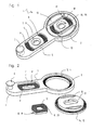
- the suspension element 1 shown in the drawing has a circular ring 2 with a circumferential ring step 3 (FIG. FIG. 2 ) on its inner circumference.
- An end face of the annular step 3 has a radial corrugation 4, which is part of a yet to be explained form-fitting device against rotation.
- an elongated tongue 5 radially outward, which ends with a semicircle and, in the embodiment, a hook 6 at its end.
- the tongue 5 is integral with the annulus 2, and the tongue 5 and the annulus 2 are of equal thickness.
- the tongue 5 has an elongated bore 7 ( FIG. 2 ), which extends radially to the annulus 2.
- the elongated bore 7 is located at the bottom of an elongate, flat countersink 8 with parallel side walls and circular end walls.
- the bottom of the countersink 8 has a corrugation 9 transverse to the slot 7.
- the corrugation 9 is part of a yet to be explained form-fitting device against displacement.
- a perforated disc 10 is arranged with a circular hole 11.
- the hole 11 is congruent with the elongated bore 7.
- Die Perforated disk 10 has two straight, mutually parallel edges, the distance of which corresponds to a width of the countersink 8.
- the perforated disc 10 is displaceably guided in the longitudinal direction of the oblong bore 7 in the oblong countersink 8 of the tongue 5 of the suspension element 1.
- One of the bottom of the countersink 8 facing end face of the perforated disc 10 is provided with a corrugation 12 (FIG. FIG. 2 ), which is complementary to the corrugation 9 of the bottom of the countersink 8.
- the perforated plate 10 is secured by positive engagement against displacement.
- the two corrugations 9, 12 form a form-locking device against displacement of the perforated disc 10.
- FIG. 2 the perforated disc 10 is drawn upside down with its underside assigned to the bottom of the countersink 8.
- a circular disk 13 is accommodated, which has an annular step 14 (FIG. FIG. 2 ), which is complementary to the ring stage 3 of the annulus 2.
- the circular disc 13 is rotatable in the circular ring 2.
- An end face of the annular step 14 has a radial corrugation 15 which is complementary to the corrugation 4 of the annular step 3 of the annulus 2.
- the corrugations 4, 15 form a form-fitting device against rotation of the circular disc 13.
- Like the perforated disc 10 is also the circular disc 13 in FIG. 2 reversed drawn with its bottom and its corrugation 15 upwards.
- the circular disk 13 has a slot 16 which passes through its center.
- the slot 16 of the circular disc 13 is thus in extension of the elongated bore 7 in the tongue 5 of the suspension element 1, which extends radially to the annulus 2.
- the direction of its slot 16 can be changed.
- the circular disc 13 has a further oblong countersink 17, at the bottom of which the oblong hole 16 is located.
- One reason of the countersink 17 has a corrugation running transversely to the oblong hole 16, which cooperates as a positive locking device against displacement with a complementary corrugation of an end face of a further perforated disc 19, which is designed to coincide with the perforated disc 10 already described.
- the further perforated disc 19 has a further hole 20.
- all parts 1, 10, 13, 19 of the suspension element 1 plastic parts. Another choice of material is possible.
Landscapes
- Processing Of Stones Or Stones Resemblance Materials (AREA)
- Snaps, Bayonet Connections, Set Pins, And Snap Rings (AREA)
Abstract
Description
- Die Erfindung betrifft ein Aufhängeelement zum Aufhängen von Gegenständen wie beispielsweise Bildern oder Spiegeln an einer Wand mit den Merkmalen des Oberbegriffs des Anspruchs 1. Das Aufhängeelement kann beispielsweise einen Haken, ein Loch, eine Öse oder einen Ring zum Aufhängen des Gegenstands aufweisen.
- Ein derartiges Aufhängeelement ist bekannt aus der
EP 993 797 A1 - Aufgabe der Erfindung ist, ein justierbares Aufhängeelement vorzuschlagen, dessen Halt verbessert ist.
- Diese Aufgabe wird erfindungsgemäß durch die Merkmale des Anspruchs 1 gelöst. Wie das bekannte Aufhängeelement weist das erfindungsgemäße Aufhängeelement ein ein Langloch aufweisendes Element auf, das am Aufhängeelement drehbar angeordnet ist, so dass die Richtung des Langlochs in Bezug auf das Aufhängeelement einstellbar ist. Zusätzlich weist das erfindungsgemäße Aufhängeelement eine längliche Bohrung auf. Der Begriff "längliche Bohrung" meint insbesondere auch ein Langloch und wird zur Abgrenzung gegenüber dem Langloch des drehbaren Elements verwendet. Dadurch ist eine Befestigung des Aufhängeelements mit zwei Schrauben möglich, was den Halt des Aufhängeelements an beispielsweise einer Wand erhöht. Die längliche Bohrung bietet eine Justiermöglichkeit in seiner Längsrichtung.
- Die längliche Bohrung kann grundsätzlich ebenfalls verstellbar, insbesondere drehbar sein. Eine Ausgestaltung der Erfindung sieht vor, dass die längliche Bohrung starr am Aufhängeelement ist. Dadurch ist die Anzahl der Justiermöglichkeiten eingeschränkt, was die Handhabung bei der Befestigung des Aufhängeelements vereinfacht. Außerdem verhindert die starre längliche Bohrung ein ungewolltes Verstellen, insbesondere ein Drehen um seine Hochachse.
- In bevorzugter Ausgestaltung der Erfindung ist die längliche Bohrung des Aufhängeelements so ausgerichtet, dass sich das Langloch des drehbaren Elements in seiner Verlängerung befindet. Auf diese Weise ist eine Anpassung an den Abstand zweier Befestigungsschrauben bzw. an den Abstand zweier Bohrlöcher zum Eindrehen der Befestigungsschrauben möglich. Ein ungenauer Bohrungsabstand wird ausgeglichen, der durch seitliches Verlaufen eines Bohrers beim Bohren auftreten kann.
- In bevorzugter Ausgestaltung der Erfindung ist das drehbare Element eine kreisförmige Scheibe, die in einer komplementären Aufnahme des Aufhängeelements aufgenommen ist. Dadurch ist in einfacher Weise eine Drehlagerung der kreisförmigen, das Langloch aufweisenden Scheibe möglich.
- Eine Ausgestaltung der Erfindung sieht eine Lochscheibe vor, die dem Langloch und/oder der länglichen Bohrung des Aufhängeelements zugeordnet ist und deren Loch ungefähr gleich lang wie breit ist. Diese Formulierung ist zur Abgrenzung von einem Langloch gewählt worden. Das Loch der Lochscheibe ist insbesondere kreisförmig, es ist allerdings auch beispielsweise ein quadratisches oder sonstiges Mehrkantloch denkbar. Das Loch der Lochscheibe fluchtet mit dem Langloch bzw. der länglichen Bohrung und die Lochscheibe ist in Längsrichtung des Langlochs bzw. der länglichen Bohrung verschiebbar. Mit der Lochscheibe wird eine Befestigungsschraube in Längsrichtung des Langlochs bzw. der länglichen Bohrung fixiert und ein ungewolltes Verstellen in Längsrichtung beispielsweise beim Festziehen der Befestigungsschraube wird vermieden. Die Lochscheibe kann am drehbaren Element für dessen Langloch und/oder an der länglichen Bohrung vorgesehen sein. Vorzugsweise ist sowohl für das Langloch als auch die längliche Bohrung eine Lochscheibe vorgesehen.
- Eine Ausgestaltung der Erfindung weist eine Formschlusseinrichtung gegen Verschieben der Lochscheibe auf. Hierbei kann es sich um eine Riffelung quer zum Langloch handeln, die eine Verschiebung der Lochscheibe in Längsrichtung des Langlochs verhindert.
- Eine Ausgestaltung der Erfindung sieht eine Formschlusseinrichtung gegen Verdrehen des drehbaren, das Langloch aufweisenden Elements vor. Auch hier kann es sich um eine Riffelung, allerdings eine radiale Riffelung handeln.
- Die Erfindung wird nachfolgend anhand eines in der Zeichnung dargestellten Ausführungsbeispiels näher erläutert. Es zeigen:
- Figur 1
- ein erfindungsgemäßes Aufhängeelement in perspektivischer Darstellung; und
- Figur 2
- Einzelteile des Aufhängeelements aus
Figur 1 . - Das in der Zeichnung dargestellte Aufhängeelement 1 weist einen Kreisring 2 mit einer umlaufenden Ringstufe 3 (
Figur 2 ) an seinem Innenumfang auf. Eine Stirnfläche der Ringstufe 3 weist eine radiale Riffelung 4 auf, die Teil einer noch zu erläuternden Formschlusseinrichtung gegen Verdrehen ist. - Vom Kreisring 2 steht eine längliche Zunge 5 radial nach außen ab, die mit einem Halbkreis endet und, im Ausführungsbeispiel, einen Haken 6 an ihrem Ende aufweist. Die Zunge 5 ist einstückig mit dem Kreisring 2, und die Zunge 5 und der Kreisring 2 weisen eine gleiche Dicke auf.
- Die Zunge 5 weist eine längliche Bohrung7 auf (
Figur 2 ), die radial zum Kreisring 2 verläuft. Die längliche Bohrung 7 befindet sich am Grund einer länglichen, flachen Ansenkung 8 mit parallelen Seitenwänden und kreisförmigen Stirnwänden. Der Grund der Ansenkung 8 weist eine Riffelung 9 quer zum Langloch 7 auf. Die Riffelung 9 ist Teil einer noch zu erläuternden Formschlusseinrichtung gegen Verschieben. - In der Ansenkung 8 ist eine Lochscheibe 10 mit einem kreisförmigen Loch 11 angeordnet. Das Loch 11 ist deckungsgleich mit der länglichen Bohrung 7. Die Lochscheibe 10 weist zwei gerade, zueinander parallele Ränder auf, deren Abstand voneinander einer Breite der Ansenkung 8 entspricht. Die Lochscheibe 10 ist in Längsrichtung der länglichen Bohrung 7 verschiebbar in der länglichen Ansenkung 8 der Zunge 5 des Aufhängeelements 1 geführt. Eine dem Grund der Ansenkung 8 zugewandte Stirnfläche der Lochscheibe 10 ist mit einer Riffelung 12 (
Figur 2 ) versehen, die komplementär zur Riffelung 9 des Grunds der Ansenkung 8 ist. Stehen die Riffelungen 9, 12 in Eingriff miteinander, ist die Lochscheibe 10 durch Formschluss gegen Verschieben gesichert. Die beiden Riffelungen 9, 12 bilden eine Formschlusseinrichtung gegen Verschieben der Lochscheibe 10. InFigur 2 ist die Lochscheibe 10 umgekehrt mit ihrer dem Grund der Ansenkung 8 zugeordneten Unterseite nach oben gezeichnet. - Im Kreisring 2 ist eine Kreisscheibe 13 aufgenommen, die eine Ringstufe 14 (
Figur 2 ) aufweist, die komplementär zur Ringstufe 3 des Kreisrings 2 ist. Die Kreisscheibe 13 ist drehbar im Kreisring 2. Eine Stirnfläche der Ringstufe 14 weist eine radiale Riffelung 15 auf, die komplementär zur Riffelung 4 der Ringstufe 3 des Kreisrings 2 ist. Stehen die beiden Riffelungen 4, 15 in Eingriff miteinander, verhindern sie ein Drehen der Kreisscheibe 13 im Kreisring 2. Die Riffelungen 4, 15 bilden eine Formschlusseinrichtung gegen Verdrehen der Kreisscheibe 13. Wie die Lochscheibe 10 ist auch die Kreisscheibe 13 inFigur 2 umgekehrt mit ihrer Unterseite und ihrer Riffelung 15 nach oben gezeichnet. - Die Kreisscheibe 13 weist ein Langloch 16 auf, das durch ihre Mitte geht. Das Langloch 16 der Kreisscheibe 13 befindet sich damit in Verlängerung der länglichen Bohrung 7 in der Zunge 5 des Aufhängeelements 1, das radial zum Kreisring 2 verläuft. Durch Drehen der Kreisscheibe 13 lässt sich die Richtung seines Langlochs 16 verändern.
- Zusätzlich zu der Ansenkung 8 im Bereich der Zunge 5 weist die Kreisscheibe 13 eine weitere längliche Ansenkung 17 auf, an deren Grund sich das Langloch 16 befindet. Ein Grund der Ansenkung 17 weist eine quer zum Langloch 16 verlaufende Riffelung auf, die als Formschlusseinrichtung gegen Verschieben mit einer komplementären Riffelung einer Stirnfläche einer weiteren Lochscheibe 19 zusammenwirkt, die übereinstimmend mit der bereits beschriebenen Lochscheibe 10 ausgebildet ist. Die weitere Lochscheibe 19 weist ein weiteres Loch 20 auf. Zur Befestigung des Aufhängeelements 1 werden zwei nicht dargestellte Befestigungsschrauben durch die Löcher 11, 20 der beiden Lochscheiben 10, 19 und durch das Langloch 16 und die längliche Bohrung 7 gesteckt und in zwei zuvor gebohrte, nicht dargestellte Bohrlöcher in einer Wand eingeschraubt. Solange die Befestigungsschrauben nicht festgezogen sind, lässt sich durch Verschieben der Lochscheibe 10 an der Zunge 5 des Aufhängeelements 1 ein Abstand der beiden Löcher 11, 20 an einen Abstand der Bohrlöcher anpassen. Durch Drehen der Kreisscheibe 13 und Verschieben der ihr zugeordneten weiteren Lochscheibe 19 ist eine Verstellung in Querrichtung bzw. in jeder erforderlichen Richtung möglich.
- Im Ausführungsbeispiel sind alle Teile 1, 10, 13, 19 des Aufhängeelements 1 Kunststoffteile. Eine andere Materialwahl ist möglich.
-
- 1
- Aufhängeelement
- 2
- Kreisring
- 3
- Ringstufe
- 4
- Riffelung
- 5
- Zunge
- 6
- Haken
- 7
- längliche Bohrung
- 8
- Ansenkung
- 9
- Riffelung
- 10
- Lochscheibe
- 11
- Loch
- 12
- Riffelung
- 13
- Kreisscheibe
- 14
- Ringstufe
- 15
- Riffelung
- 16
- Langloch
- 17
- weitere Ansenkung
- 18
- Riffelung
- 19
- weitere Lochscheibe
- 20
- weiteres Loch
Claims (7)
- Aufhängeelement, mit einem ein Langloch (16) aufweisenden Element (13), das drehbar am Aufhängeelement (1) angeordnet ist, dadurch gekennzeichnet, dass das Aufhängeelement (1) eine längliche Bohrung (7) aufweist.
- Aufhängeelement nach Anspruch 1, dadurch gekennzeichnet, dass die längliche Bohrung (7) des Aufhängeelements (1) starr ist.
- Aufhängeelement nach Anspruch 1, dadurch gekennzeichnet, dass das Langloch (16) des drehbaren Elements (13) in Verlängerung der länglichen Bohrung (7) des Aufhängeelements (1) angeordnet ist.
- Aufhängeelement nach Anspruch 1, dadurch gekennzeichnet, dass das drehbare Element (13) eine kreisförmige Scheibe ist, die in einer komplementären Aufnahme (3) des Aufhängeelements (1) aufgenommen ist.
- Aufhängeelement nach Anspruch 1, dadurch gekennzeichnet, dass das Aufhängeelement (1) eine Lochscheibe (10, 19) aufweist, deren Loch (11, 20) gleich lang wie breit ist und die in Längsrichtung der länglichen Bohrung (7) und/oder des Langlochs (16) verschiebbar am Aufhängeelement (1) und/oder an dem drehbaren, das Langloch (16) aufweisenden Element (13) angeordnet ist.
- Aufhängeelement nach Anspruch 5, dadurch gekennzeichnet, dass das Aufhängeelement (1) eine Formschlusseinrichtung (9, 12, 18) gegen Verschieben der Lochscheibe (10, 19) aufweist.
- Aufhängeelement nach Anspruch 1, dadurch gekennzeichnet, dass das Aufhängeelement (1) eine weitere Formschlusseinrichtung (4, 15) gegen Verdrehen des drehbaren, das Langloch (16) aufweisenden Elements (13) aufweist.
Applications Claiming Priority (1)
| Application Number | Priority Date | Filing Date | Title |
|---|---|---|---|
| DE102007051460A DE102007051460A1 (de) | 2007-10-27 | 2007-10-27 | Aufhängeelement |
Publications (1)
| Publication Number | Publication Date |
|---|---|
| EP2052646A1 true EP2052646A1 (de) | 2009-04-29 |
Family
ID=40263302
Family Applications (1)
| Application Number | Title | Priority Date | Filing Date |
|---|---|---|---|
| EP08017265A Withdrawn EP2052646A1 (de) | 2007-10-27 | 2008-10-01 | Aufhängeelement für ein Bild, einen Spiegel oder dgl. |
Country Status (2)
| Country | Link |
|---|---|
| EP (1) | EP2052646A1 (de) |
| DE (1) | DE102007051460A1 (de) |
Cited By (4)
| Publication number | Priority date | Publication date | Assignee | Title |
|---|---|---|---|---|
| DE102008039802B4 (de) * | 2008-08-14 | 2010-11-25 | Astec Gmbh Design Beschlaege | Justierbare Wandhalterung |
| ITRA20100010A1 (it) * | 2010-04-26 | 2011-10-27 | Conteco S R L | Gancio appendiquadro regolabile e bloccabile |
| WO2017006193A3 (en) * | 2015-05-15 | 2017-03-02 | Lakinnova S.R.L. | Support device |
| WO2019166421A1 (de) * | 2018-02-28 | 2019-09-06 | Alexander Schophoff | Befestigungssystem zum befestigen eines gegenstands an einem träger |
Citations (3)
| Publication number | Priority date | Publication date | Assignee | Title |
|---|---|---|---|---|
| DE436682C (de) * | 1926-11-05 | Otto Koehler | In der Wagerechten und Senkrechten verstellbare, aus zwei aneinander gefuehrten Teilen bestehende Bilderoese | |
| US4641807A (en) * | 1985-08-23 | 1987-02-10 | Orville Phillips | Three-dimensionally adjustable picture hanger |
| EP0993797A1 (de) | 1998-10-13 | 2000-04-19 | Fischerwerke Arthur Fischer GmbH & Co. KG | Aufhängeelement für einen Bilderrahmen, Spiegel oder dgl. |
Family Cites Families (8)
| Publication number | Priority date | Publication date | Assignee | Title |
|---|---|---|---|---|
| US2681194A (en) * | 1950-01-20 | 1954-06-15 | Wilmet P Halvorsen | Self-centering device for hanging pictures and the like |
| DE1816033U (de) * | 1960-05-14 | 1960-08-04 | Bodenschatz A G R | Vorrichtung zur befestigung eines gegenstandes an einem traeger. |
| DE1901685C3 (de) * | 1969-01-15 | 1975-08-21 | Gerhard 5828 Ennepetal Vormann | Aufhängevorrichtung für einen Wandschrank |
| DE8401307U1 (de) * | 1984-01-18 | 1984-04-05 | Mutscher, Kurt, 4000 Düsseldorf | Vorrichtung zum aufhaengen von gegenstaenden, insbesondere von bildern, spiegeln od. dgl. |
| US5069411A (en) * | 1990-10-10 | 1991-12-03 | Murphy James P | Picture hanger |
| US5752356A (en) * | 1996-12-16 | 1998-05-19 | Miklavic; Thomas D. | Detachable wall trim |
| US6966534B2 (en) * | 2002-08-22 | 2005-11-22 | Peter Kamenstein | Wire system for hanging picture frames |
| US20040056167A1 (en) * | 2002-09-20 | 2004-03-25 | Vogt William R. | Tolerant mounting apparatus |
-
2007
- 2007-10-27 DE DE102007051460A patent/DE102007051460A1/de not_active Withdrawn
-
2008
- 2008-10-01 EP EP08017265A patent/EP2052646A1/de not_active Withdrawn
Patent Citations (3)
| Publication number | Priority date | Publication date | Assignee | Title |
|---|---|---|---|---|
| DE436682C (de) * | 1926-11-05 | Otto Koehler | In der Wagerechten und Senkrechten verstellbare, aus zwei aneinander gefuehrten Teilen bestehende Bilderoese | |
| US4641807A (en) * | 1985-08-23 | 1987-02-10 | Orville Phillips | Three-dimensionally adjustable picture hanger |
| EP0993797A1 (de) | 1998-10-13 | 2000-04-19 | Fischerwerke Arthur Fischer GmbH & Co. KG | Aufhängeelement für einen Bilderrahmen, Spiegel oder dgl. |
Cited By (4)
| Publication number | Priority date | Publication date | Assignee | Title |
|---|---|---|---|---|
| DE102008039802B4 (de) * | 2008-08-14 | 2010-11-25 | Astec Gmbh Design Beschlaege | Justierbare Wandhalterung |
| ITRA20100010A1 (it) * | 2010-04-26 | 2011-10-27 | Conteco S R L | Gancio appendiquadro regolabile e bloccabile |
| WO2017006193A3 (en) * | 2015-05-15 | 2017-03-02 | Lakinnova S.R.L. | Support device |
| WO2019166421A1 (de) * | 2018-02-28 | 2019-09-06 | Alexander Schophoff | Befestigungssystem zum befestigen eines gegenstands an einem träger |
Also Published As
| Publication number | Publication date |
|---|---|
| DE102007051460A1 (de) | 2009-04-30 |
Similar Documents
| Publication | Publication Date | Title |
|---|---|---|
| DE60037585T2 (de) | Montagesystem und rückhalteclip | |
| DE19949926C1 (de) | Leitungssystem | |
| EP1613890B1 (de) | Standfuss | |
| DE102008062894A1 (de) | Distanzvorrichtung und Befestigungsanordnung mit Distanzvorrichtung | |
| WO1991017329A1 (de) | Gelenkarmmarkise | |
| DE102010022415A1 (de) | Montagelasche für abgehängte Decken | |
| DE102007051460A1 (de) | Aufhängeelement | |
| DE2455805A1 (de) | Einstellbares tuerband und scharnier | |
| DE9407340U1 (de) | Befestigungselement für Warenträger | |
| DE19902171A1 (de) | Vorrichtung zum Befestigen einer Wandstange | |
| EP0993797B1 (de) | Aufhängeelement für einen Bilderrahmen, Spiegel oder dgl. | |
| EP1799533A2 (de) | Befestigung eines adapters für fahrräder | |
| EP0040180A1 (de) | Montagegestell | |
| DE102018118772B4 (de) | Stecknusshalterahmenbaugruppe | |
| EP2157266B1 (de) | Scharnier für ein mit einer Tür versehenes Möbelstück | |
| DE3128260C2 (de) | ||
| DE19506417B4 (de) | Vorrichtung zum Errichten eines Schutzgeländers im Bereich des Ortgangs eines Hausdaches | |
| EP0413396B1 (de) | Haushaltgerät, z.B. Geschirrspülmaschine | |
| DE202019005506U1 (de) | Befestigungssystem zum Befestigen eines Gegenstands an einem Träger | |
| DE10344457A1 (de) | Aufhängevorrichtung | |
| EP2811192B1 (de) | Schwenkrollenbaugruppe für einen Rollstuhl | |
| EP1081392A2 (de) | Verbindungsbeschlag zum Gegeneinanderspannen zweier Teile | |
| DE2908385A1 (de) | Beschlag zur verstellbaren aufhaengung eines moebelelements | |
| DE3023760C2 (de) | Aufhängebeschlag für Hängeschränke u.dgl. | |
| EP1464767B1 (de) | Vorrichtung zur Befestigung eines wandhängenden sanitärkeramischen Gegenstandes |
Legal Events
| Date | Code | Title | Description |
|---|---|---|---|
| PUAI | Public reference made under article 153(3) epc to a published international application that has entered the european phase |
Free format text: ORIGINAL CODE: 0009012 |
|
| AK | Designated contracting states |
Kind code of ref document: A1 Designated state(s): AT BE BG CH CY CZ DE DK EE ES FI FR GB GR HR HU IE IS IT LI LT LU LV MC MT NL NO PL PT RO SE SI SK TR |
|
| AX | Request for extension of the european patent |
Extension state: AL BA MK RS |
|
| 17Q | First examination report despatched |
Effective date: 20090930 |
|
| 17P | Request for examination filed |
Effective date: 20090831 |
|
| AKX | Designation fees paid |
Designated state(s): AT BE BG CH CY CZ DE DK EE ES FI FR GB GR HR HU IE IS IT LI LT LU LV MC MT NL NO PL PT RO SE SI SK TR |
|
| GRAP | Despatch of communication of intention to grant a patent |
Free format text: ORIGINAL CODE: EPIDOSNIGR1 |
|
| STAA | Information on the status of an ep patent application or granted ep patent |
Free format text: STATUS: THE APPLICATION IS DEEMED TO BE WITHDRAWN |
|
| 18D | Application deemed to be withdrawn |
Effective date: 20101104 |