EP2051848B1 - Leichtbauplatte - Google Patents
Leichtbauplatte Download PDFInfo
- Publication number
- EP2051848B1 EP2051848B1 EP07787906A EP07787906A EP2051848B1 EP 2051848 B1 EP2051848 B1 EP 2051848B1 EP 07787906 A EP07787906 A EP 07787906A EP 07787906 A EP07787906 A EP 07787906A EP 2051848 B1 EP2051848 B1 EP 2051848B1
- Authority
- EP
- European Patent Office
- Prior art keywords
- end section
- covering
- accordance
- layer
- section
- Prior art date
- Legal status (The legal status is an assumption and is not a legal conclusion. Google has not performed a legal analysis and makes no representation as to the accuracy of the status listed.)
- Active
Links
- 238000004519 manufacturing process Methods 0.000 claims abstract description 9
- 208000029154 Narrow face Diseases 0.000 claims abstract 10
- 239000000463 material Substances 0.000 claims description 39
- 238000000034 method Methods 0.000 claims description 25
- 230000003313 weakening effect Effects 0.000 claims description 12
- 239000002023 wood Substances 0.000 claims description 12
- 238000003801 milling Methods 0.000 claims description 10
- 230000008569 process Effects 0.000 claims description 6
- 238000002360 preparation method Methods 0.000 claims description 3
- 239000000565 sealant Substances 0.000 claims description 3
- 239000006261 foam material Substances 0.000 claims 4
- 230000004075 alteration Effects 0.000 claims 2
- 229920002678 cellulose Polymers 0.000 claims 2
- 239000001913 cellulose Substances 0.000 claims 2
- 239000010410 layer Substances 0.000 description 184
- 239000006260 foam Substances 0.000 description 19
- 239000011248 coating agent Substances 0.000 description 9
- 238000000576 coating method Methods 0.000 description 9
- 239000011111 cardboard Substances 0.000 description 6
- 239000011094 fiberboard Substances 0.000 description 6
- 238000007789 sealing Methods 0.000 description 5
- 230000008901 benefit Effects 0.000 description 4
- 150000001875 compounds Chemical class 0.000 description 4
- 239000004831 Hot glue Substances 0.000 description 3
- 238000004026 adhesive bonding Methods 0.000 description 3
- 230000001070 adhesive effect Effects 0.000 description 3
- 230000008859 change Effects 0.000 description 3
- 239000011093 chipboard Substances 0.000 description 3
- 238000010276 construction Methods 0.000 description 3
- 238000003754 machining Methods 0.000 description 3
- 239000003973 paint Substances 0.000 description 3
- 238000007493 shaping process Methods 0.000 description 3
- 239000000853 adhesive Substances 0.000 description 2
- 230000035515 penetration Effects 0.000 description 2
- 239000007787 solid Substances 0.000 description 2
- 239000006228 supernatant Substances 0.000 description 2
- GHYOCDFICYLMRF-UTIIJYGPSA-N (2S,3R)-N-[(2S)-3-(cyclopenten-1-yl)-1-[(2R)-2-methyloxiran-2-yl]-1-oxopropan-2-yl]-3-hydroxy-3-(4-methoxyphenyl)-2-[[(2S)-2-[(2-morpholin-4-ylacetyl)amino]propanoyl]amino]propanamide Chemical compound C1(=CCCC1)C[C@@H](C(=O)[C@@]1(OC1)C)NC([C@H]([C@@H](C1=CC=C(C=C1)OC)O)NC([C@H](C)NC(CN1CCOCC1)=O)=O)=O GHYOCDFICYLMRF-UTIIJYGPSA-N 0.000 description 1
- 241000771208 Buchanania arborescens Species 0.000 description 1
- 239000004640 Melamine resin Substances 0.000 description 1
- 229920000877 Melamine resin Polymers 0.000 description 1
- 240000007182 Ochroma pyramidale Species 0.000 description 1
- 229910052782 aluminium Inorganic materials 0.000 description 1
- XAGFODPZIPBFFR-UHFFFAOYSA-N aluminium Chemical compound [Al] XAGFODPZIPBFFR-UHFFFAOYSA-N 0.000 description 1
- 230000004888 barrier function Effects 0.000 description 1
- 238000005452 bending Methods 0.000 description 1
- 239000002131 composite material Substances 0.000 description 1
- 229940125797 compound 12 Drugs 0.000 description 1
- 239000012792 core layer Substances 0.000 description 1
- 238000005520 cutting process Methods 0.000 description 1
- 230000001419 dependent effect Effects 0.000 description 1
- 230000005489 elastic deformation Effects 0.000 description 1
- -1 hardboard Substances 0.000 description 1
- 229910052500 inorganic mineral Inorganic materials 0.000 description 1
- 238000009413 insulation Methods 0.000 description 1
- 239000004922 lacquer Substances 0.000 description 1
- 230000007774 longterm Effects 0.000 description 1
- 229910052751 metal Inorganic materials 0.000 description 1
- 239000002184 metal Substances 0.000 description 1
- 239000011707 mineral Substances 0.000 description 1
- 238000010422 painting Methods 0.000 description 1
- 239000011087 paperboard Substances 0.000 description 1
- 239000004033 plastic Substances 0.000 description 1
- 239000011120 plywood Substances 0.000 description 1
- 230000002787 reinforcement Effects 0.000 description 1
- 230000003014 reinforcing effect Effects 0.000 description 1
- 230000035939 shock Effects 0.000 description 1
- 241000894007 species Species 0.000 description 1
- 239000002966 varnish Substances 0.000 description 1
- 239000013585 weight reducing agent Substances 0.000 description 1
- 210000002268 wool Anatomy 0.000 description 1
Images


Classifications
-
- E—FIXED CONSTRUCTIONS
- E04—BUILDING
- E04C—STRUCTURAL ELEMENTS; BUILDING MATERIALS
- E04C2/00—Building elements of relatively thin form for the construction of parts of buildings, e.g. sheet materials, slabs, or panels
- E04C2/30—Building elements of relatively thin form for the construction of parts of buildings, e.g. sheet materials, slabs, or panels characterised by the shape or structure
- E04C2/34—Building elements of relatively thin form for the construction of parts of buildings, e.g. sheet materials, slabs, or panels characterised by the shape or structure composed of two or more spaced sheet-like parts
- E04C2/36—Building elements of relatively thin form for the construction of parts of buildings, e.g. sheet materials, slabs, or panels characterised by the shape or structure composed of two or more spaced sheet-like parts spaced apart by transversely-placed strip material, e.g. honeycomb panels
- E04C2/365—Building elements of relatively thin form for the construction of parts of buildings, e.g. sheet materials, slabs, or panels characterised by the shape or structure composed of two or more spaced sheet-like parts spaced apart by transversely-placed strip material, e.g. honeycomb panels by honeycomb structures
-
- B—PERFORMING OPERATIONS; TRANSPORTING
- B29—WORKING OF PLASTICS; WORKING OF SUBSTANCES IN A PLASTIC STATE IN GENERAL
- B29C—SHAPING OR JOINING OF PLASTICS; SHAPING OF MATERIAL IN A PLASTIC STATE, NOT OTHERWISE PROVIDED FOR; AFTER-TREATMENT OF THE SHAPED PRODUCTS, e.g. REPAIRING
- B29C63/00—Lining or sheathing, i.e. applying preformed layers or sheathings of plastics; Apparatus therefor
- B29C63/02—Lining or sheathing, i.e. applying preformed layers or sheathings of plastics; Apparatus therefor using sheet or web-like material
- B29C63/04—Lining or sheathing, i.e. applying preformed layers or sheathings of plastics; Apparatus therefor using sheet or web-like material by folding, winding, bending or the like
-
- B—PERFORMING OPERATIONS; TRANSPORTING
- B32—LAYERED PRODUCTS
- B32B—LAYERED PRODUCTS, i.e. PRODUCTS BUILT-UP OF STRATA OF FLAT OR NON-FLAT, e.g. CELLULAR OR HONEYCOMB, FORM
- B32B3/00—Layered products comprising a layer with external or internal discontinuities or unevennesses, or a layer of non-planar shape; Layered products comprising a layer having particular features of form
- B32B3/02—Layered products comprising a layer with external or internal discontinuities or unevennesses, or a layer of non-planar shape; Layered products comprising a layer having particular features of form characterised by features of form at particular places, e.g. in edge regions
Definitions
- the present invention relates to a lightweight board, comprising two cellulosic material-containing cover layers, wherein at least one of the cover layers is formed by a wood-based panel, with a central layer in the form of a honeycomb, which is arranged between the two cover layers, and with a covered narrow surface extending from the two cover layers extends over the middle layer, wherein at least a part of an end portion of at least one of the cover layers extends at an angle to a longitudinal plane of the cover layers.
- the invention relates to a method for producing a lightweight board with two cellulosic material-containing cover layers, wherein at least one of the cover layers is formed by a wood-based panel, with a central layer in the form of a honeycomb, which is arranged between the two cover layers, and with a covered narrow surface, the extends from the two cover layers over the middle layer.
- Lightweight panels with cover layers containing cellulosic material, for example cover layers made of a wood material, are well known in the prior art. Also in furniture and interior design, these are used for a long time in a variety of ways. The main field of application was and is the door construction here. So it is especially in room doors, which are therefore subject to low requirements in terms of heat and sound insulation, usually a frame member with a honeycomb core on both sides to plank and this then continue to process the corresponding holes, millings, etc. to a door element.
- the manufacturer of furniture does not need to manufacture lightweight panels today, as was the case earlier.
- a frame had to be made, possibly with several crossbars, on which the top layers were then applied and which had to accommodate the various fittings.
- cover layers lightweight fiber boards, mineral insulating wool, cardboard honeycomb or the like were introduced. This gave the item more compactness and possibly improved stability.
- the outer layers also had to be elaborately surface-treated in separate operations. For example, veneered or otherwise coated hardboards were used as cover layers, and the finished element can only be given its final surface by final painting.
- cover plates Today, lightweight panels are increasingly being manufactured industrially. For this purpose, a light middle layer is provided with cover plates, usually by gluing, so that a large-format, frameless composite arises.
- cover plates mostly made of a wood material such as chipboard or fiberboard, used.
- the plates used may already be coated, that is to say be provided with a laminate, a paint, a pressure with a seal, a melamine resin layer, a veneer, etc.
- cardboard honeycomb or foam boards are preferred.
- Honeycomb materials made of materials other than paper or cardboard may also be useful for certain purposes. Thus, thinnest plate materials or even thin-walled metal, for example made of aluminum, can be used for this purpose.
- middle layers of light wood materials such as corresponding chipboard or fiberboard or solid wood low density, such as balsa wood.
- corresponding recesses are basically all materials for use as a light middle layer possible.
- wood species are used for that, although not particularly low weight, but are well available and can be easily edited with cutting tools.
- light middle layers of bundles of bundles which are cut together to form flat structures, so that then the length of the stalk sections corresponds to the thickness of the middle layer known.
- the plates thus produced are then divided into the desired size. Depending on the intended use of the resulting elements they are then provided with edges or bars or an at least partially encircling frame is subsequently introduced. This is done by milling the edge area and subsequent gluing a frame profile, which in turn consists mostly of a wood material. Through an appropriate profiling of Kantenausfräsung it is also possible to achieve a force and / or positive fixation. The latter is achieved by a complementarily shaped profile is held positively by elastic deformation of the remaining cover plate layer.
- force and / or positive connection and an adhesive connection can be combined.
- a postforming process is understood to mean a surface coating of the narrow surface in which the upper and / or lower side coating material is used as edge material.
- the coating material is applied to the top or bottom of a plate material to be coated.
- a sufficient material supernatant is then left in the region of the narrow surface to be coated or produced by suitable milling of the plate ("direct postforming"), which is flexibilized in a suitable manner, usually by supplying heat.
- the flexibilized material supernatant is bent around the narrow surface to be coated and glued.
- the narrow surface may have a profiling, for example, a quarter-rod profile is preferred in kitchen worktops.
- a softforming process is generally understood to be a subsequent coating of a first profiled narrow surface with a material cut to size specifically for the narrow surface. It can be about the same material used to coat the large areas.
- the WO 03/084740 A1 discloses a lightweight board of the type mentioned above with two cover layers of a wood-based panel, comprising a structural layer of wood material and a laminated decorative layer, with a central layer, which is disposed between the two cover layers and a frame and an enclosed filling material having, for example, honeycomb structure, and with a covered narrow surface which extends from the two cover layers over the middle layer, wherein an end portion of a cover layer extends at an angle to the longitudinal plane of the cover layers.
- the cover layer in question is deformable in the end section in question by a weakening of the cross section by means of recesses and abuts at one edge with the other cover layer.
- an end portion of the respective cover layer is made malleable by milling grooves, the cover layer then placed on the middle layer and finally bent the end portion to the narrow surface.
- a lightweight board of the type described above but has a relatively high weight.
- the invention is therefore the technical problem of specifying a lightweight panel of the type mentioned, with a weight reduction is achieved.
- the edge region of the lightweight board which has the narrow surface
- at least one of the two cellulosic material-containing cover layers can be individually deformed and used in particular as reinforcement of the edge region. Since the material of the cover layer has a higher stability than that of the middle layer and can thus be subjected to higher loads, according to the invention a surprisingly simple manner results in an individually shaped end region and preferably a particularly stable edge region of a lightweight construction panel.
- Embodiments of the lightweight panel according to the invention are the subject of the dependent claims and will be described in more detail below.
- this lightweight board has a stable and impact-resistant edge, which in particular allows the use of the lightweight board in areas of high stress, for example as a kitchen worktop or table top, without any need for additional reinforcing elements. Due to the angular course of one of the cover layers or both cover layers relative to one of the longitudinal planes is also a allows individual shaping of the end region, by which a large number of different terminations can be achieved in a simple manner.
- a component in this way, which at the same time has an integrally formed thereon end strip and / or end edge in addition to the actual work area.
- end strip and / or end edge in addition to the actual work area.
- a closing bar which can be formed according to the invention in a simple manner that a part of the end portion of the upper cover sheet is bent upwards.
- an end edge can be created according to the invention in that a part of the end section, which is arranged, for example, on the side of the lightweight building board facing away from the wall, is bent downwards.
- a surface of the lightweight board is created by the deformation of the end portion, which can have the same good mechanical and technological properties everywhere, including in the region of the end strip or end edge, in particular a high stability and impact resistance.
- a reinforced edge region be made more effectively, but it is also possible to produce individually shaped end regions of the lightweight building board with a high resistance by simple means.
- At least one part of the end section of at least one of the cover layers may extend in different directions relative to a longitudinal plane of one of the cover layers, for example upwards, about one Create bottom bar or down to create a trailing edge.
- top and bottom are defined in this context according to the layer structure of the lightweight board, that is, the lightweight board has a top layer at the top, a cover layer below and a middle layer between them.
- the individual shaping of the end region of the lightweight building board according to the invention is achieved, for example, in that the part of the end section of the one cover layer extends beyond the longitudinal plane of the other cover layer.
- the part of the end section can also extend exactly to the longitudinal plane of the other cover layer or even end in front of this longitudinal plane.
- the part of the end portion of the one cover layer can also extend away from the longitudinal plane of the other cover layer, ie extend in the other direction.
- the cover layer can be deformed in the end section in accordance with an advantageous embodiment of the lightweight building board according to the invention.
- the cover layer in the end section at least in sections, a weakening of the cross section and in particular recesses, preferably grooves and / or holes, have.
- the attachment of grooves, either on the side facing the other cover layer or facing away from the side has proven to be particularly advantageous because they can be easily produced by machine and at the same time cause effective weakening of the cross section.
- Grooves, especially when they are arranged on the side facing the other cover layer also have the advantage that they allow a deformation of the end portion in a simple manner without damaging the material located around the grooves.
- the end portion is formed in the region of deformation, in particular so elastic and / or flexible that even bends of 90 ° or more, at least on the outwardly directed surface of the cover layer cause neither cracks nor fractures.
- the material of the cover layer can be provided only temporarily for the deformation process or permanently with the desired elasticity or flexibility.
- the narrow end surface covering the end portion is formed in a quarter-circle or semicircular in cross-section, whereby the risk of damage to the surface is reduced in impact on the edge. It also reduces the risk of damage to the liner material during deformation.
- At least one of the cover sheets may comprise a cellulosic material such as lignocellulose, or may be formed of a plywood board, chipboard, Oriented Strands Board (OSB) board or fiberboard, particularly hardboard, medium density fiberboard, or high density fiberboard.
- a cellulose-plastic compound is also conceivable as part of a cover layer. Designs of the cover layer in this type have the advantage that they can be made easily deformable on the one hand by weakening the cross section and on the other hand on the later outer side have a relatively high impact resistance and stability.
- the middle layer of the lightweight board may have a honeycomb, in particular cardboard honeycomb.
- the lightweight panel according to the invention is to increase the stability, in particular the dimensional stability of the edges, preferably the end portion of a cover layer at least partially connected to the other cover layer and / or the middle layer.
- the connection can be made by an adhesive, in particular hot melt adhesive or mounting foam, and / or by mechanical fastening means, in particular profiles, screws or nails.
- the inventively provided foam as well as the usable for bonding purposes mounting foam, the space between the narrow surface and the overlying Effectively fill and seal end section.
- the foam may be at least partially adapted to the shape of the narrow surface covering the end portion and in particular correspond to the shape of the end portion.
- the lightweight board according to the invention for example, for further sealing, for surface finishing, to increase the mechanical properties of the surface or for decorative purposes, have a coating.
- the coating may be a veneer, a laminate, a laminate, a paint and / or a lacquer.
- the narrow surfaces covering end portion of a cover layer and the other cover layer encounter at least in one section.
- one of the cover layers may have at least one groove.
- one or both cover layers have a toothing, wherein in the case that both cover layers have one, the respective teeth can interlock.
- a recess may be provided in this section, which is provided in particular with sealing compound. Also in the at least one groove or toothing sealant may be provided.
- the object is further in a method of the type mentioned, in particular a method for production a lightweight panel as described above, achieved by providing an exposed end portion of at least one cover sheet extending at least partially beyond a plane in which at least a portion of the narrow surface extends to form the cover sheet in the region of the end portion, in that at least a part of the exposed end section is arranged at an angle to a longitudinal plane of one of the cover layers, and that after the provision of the exposed end section a foam is applied in the area of the narrow surface. It is preferably provided that at least part of the exposed end section is arranged extending from the longitudinal plane of one cover layer in the direction of the longitudinal plane of the other cover layer and the narrow surface is arranged to cover at least partially.
- the method according to the invention has the advantage that the application of a foam in the region of the narrow surface makes it possible to dispense with a frame or bolt, as a result of which the lightweight board produced becomes significantly lighter.
- both end edges and end strips can be formed or formed, since according to the invention a variety of ways of shaping the end portion of the lightweight panel can be created.
- the part of the end portion of the one cover layer is arranged extending beyond the longitudinal plane of the other cover layer. It is also possible that a part of the end section is arranged to extend along the longitudinal plane of one of the cover layers and / or a part of the end section is arranged to run parallel or perpendicular to the longitudinal plane of one of the cover layers.
- the covering layer to be formed in the region of the later corner may have a corresponding recess, a so-called notching, as well as an exposed end section in the region of the two later edges.
- the provision of the exposed end portion can take place in that material of the middle layer and possibly also of the opposite cover layer is removed in the later edge region after the two cover layers and the middle layer have been joined to form a plate-shaped body.
- the end portion having cover layer prior to arranging the end portion having cover layer from the outset by the measure of the desired end portion larger, so that already in the connection of the respective cover layer with the middle layer, a part of the cover layer, that is, the end portion, about the narrow surface survives.
- both cover layers have an end portion extending in the direction of the respective other cover layer and the narrow surface, which is formed in this case only from the front side of the middle layer, covering, it is also conceivable, both cover layers with a to provide each exposed end portion which protrudes beyond the narrow surface plane.
- the narrow end surface covering end portion is advantageously at least partially fixed.
- the fixing can be done by gluing, in particular by means of hot melt adhesive or mounting foam, and / or mechanical fastening means, in particular profiles, screws or nails.
- the end portion can be connected for fixing with the other cover layer and / or the middle layer.
- the foam applied in the region of the narrow surface can be one which expands in the region of the narrow surface.
- the interior of the lightweight board can be protected in the long term against the ingress of moisture.
- the end section of the one cover layer extending over the narrow surface and the other cover layer preferably collide at least into one section when the narrow surface is covered by the end section of the one cover layer or by both cover layer end sections.
- at least one of the cover layers are provided with at least one groove or toothing.
- a recess may be provided which is provided in particular with sealing compound.
- the sealing compound can also be provided in the at least one groove or toothing.
- the exposed end portion is provided by the center layer and preferably the opposite top layer are at least partially removed.
- the removal can be done by machining, in particular milling.
- machining, in particular machining, of the said end section can take place simultaneously in order to make it malleable.
- the exposed end portion may be made malleable by weakening the cross-section and / or subjecting the exposed end portion to at least portions of a temperature change and / or a humidity change.
- the weakening of the cross section can also be done by reducing the material thickness of the end portion, in particular by milling grooves and / or holes. It is also conceivable to reduce the material thickness in a larger area, ie flat.
- the lightweight board can also be coated before or after the step in which the exposed end section is deformed.
- the lightweight board can be coated with a veneer, a laminate, a laminate, a paint or a varnish.
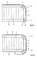
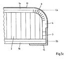
- Fig. 1 shows during its manufacture a lightweight board with two cover layers 1a, 1b - formed here as OSB plates -, with a central layer 2 - here formed as a cardboard honeycomb - which is disposed between the two cover layers, and with a narrow surface 3 to be covered in the present Case is formed quarter-circular.
- FIGS. 1a and b) An end portion 4 of the upper cover layer 1a is thereby, as based on the FIGS. 1a ) and b) is shown extending in the direction of the lower cover layer 1 b over the narrow surface 4.
- Fig. 1a the state in which the end portion 4 has been exposed by removing parts of the middle layer 2 and the lower cover layer 1b and beyond a narrow plane E, in which the narrow surface 3 extends partially and in the illustrated case perpendicular to the alignment of the cover layers 1a, 1b and the middle layer 2 and the longitudinal planes Ea, Eb runs.
- Fig. 1b shows the state after the exposed end portion 4 of the one cover layer 1a in the direction of the other cover layer 1b over the narrow surface 3 extending and this was arranged covering.
- a plurality of parallel grooves 5, which in the present case extend at an angle to the narrow surface plane E or to align the cover layer 1a, have been provided by a schematically illustrated rotating milling machine 6.
- the milling machine 6 in this case has such a broad working range that all grooves 5 necessary for the deformation can be produced with a single cut.
- the end portion 4 is bent toward the other cover sheet 1b, and a part of the end portion 4 extends at angles to the longitudinal planes Ea and Eb of the cover sheets 1a and 1b, and covers , as Fig. 1b ), then the narrow surface 3 from.
- the inside of the cover layer 1a in the region of the end portion 4 is flush on the outside of the middle layer 2 and the end face 7 of the lower cover layer 1b, which is also part of the narrow surface 3, at.
- it is connected to the narrow surface 3 by bonding, here by using a hotmelt adhesive (not shown). In this way, it is prevented that after the forming of the end portion 4 dissolves again from the narrow surface 3.
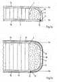
- FIG. 2 Further embodiments of the method according to the invention for producing a lightweight building board are in Fig. 2 shown. Again, two cover layers 1a, 1b are formed as OSB plate and arranged above and below a formed as a cardboard honeycomb core layer 2.
- lightweight board instead of a plurality of grooves 5 a plurality of slots 8 are provided to allow reshaping of the cover layer 1a in the direction of the opposite cover layer 1b.
- the slots 8 are arranged only in a relatively small section of the end section 4, namely only where the course of the cover layer 1a undergoes a change in direction.
- FIG. 2a shows, on the other cover layer 1b side facing a Gearing 9a provided, which engages in a correspondingly shaped toothing 9b in the narrow surface 3, to prevent the end portion 4 shifts across the course of the central layer 2 and the lower cover layer 1b.
- FIG. 2b For connecting the upper cover layers 1a with the lower cover layer 1b is how FIG. 2b ), instead of teeth provided that a part of the end portion 4 is parallel to the longitudinal plane Eb of the lower cover layer 1b, wherein the inside of the end portion 4 is bonded to the outside of the cover layer 1b. Further, another portion having a plurality of slits 8 is provided to allow the upper cover sheet 1a to be bent twice at 90 ° in its end portion, so that finally the inner side of the end portion of the one cover sheet 1a at the outer side of the other Cover layer 1b comes to rest.
- Fig. 2c The embodiment in Fig. 2c ) is essentially the same as in Fig. 2a ), but instead of a toothing now a locking connection in the form of a tongue and groove connection is provided.
- a toothing now a locking connection in the form of a tongue and groove connection is provided.
- the spring profile 20 of the cover layer 1a is locked in the corresponding groove profile 19 of the cover layer 1b, so that at least one prefixing takes place already by the latching. For final fixation can then be done, for example, a bond.
- the cover layer 1a overlaps with the front edge of the cover layer 1b, so that the Lightweight construction board narrow side can be coated without interruption.
- a coating 10 in the form of a veneer can be used for example as a kitchen worktop.
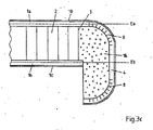
- Embodiments of a lightweight board are in Fig. 3 shown.
- Fig. 3 which essentially the embodiments of Fig. 2 also no toothing is provided at the outer end of the end section 4, but rather a recess 11.
- the recess 11 continues at the corresponding point on the outer end of the other cover layer 1b.
- the recess 11 is provided with a sealant 12.
- a foam 13 is applied in the region of the narrow surface 3, which is expanded. This foam also serves as a mounting foam, which fixes the end portion 4 in the narrow surface 3 covering state.
- FIGS. 3a ) and b) differ in that in one case the upper cover layer 1a in the end section 4 is bent only once by 90 °, whereby slots 8 are provided for this purpose (FIG. Fig. 3a )), and in the other case, the upper cover layer 1a) in End section 4 is bent twice by 90 ° ( Fig. 3b )). In the latter case, the end face of the upper cover layer 1a abuts against the end face of the lower cover layer 1b, the recess 11 provided with the sealing compound 12 being provided in this region. Furthermore, according to Fig.
- FIG. 3b shows a similar variant as Fig. 3b ), in which case here too the end section 4 has been bent twice by 90 ° in each case and slots 8 are provided to weaken the cross section.
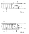
- the application of the foam 13 is exemplary in the FIGS. 4a ) and b) are shown.
- the foam 13 is applied before forming the end portion 4 on an exposed in the present case end portion 14 of the lower cover layer 1b.
- the end portion 4 of the one cover layer 1a is arranged to extend in the direction of the other cover layer 1b over the narrow surface 3.
- the Narrow surface 3 is not directly in this embodiment in contact with the inside of the end portion 4, but is still covered by this. Since the applied foam 13 expands in the cavity between the end section 4 and the narrow surface 3, it is ensured that the cover layer 1a and the cover layer 1b are sufficiently supported in the edge region towards the interior of the plate and do not yield under pressure.
- the foam 13 also has a sufficient adhesive effect to fix the end portion 4, and at the same time serves as a moisture barrier.
- the cover layer 1a can be made malleable in the region of the end section 4 by a weakening of the cross section of the cover layer 1a.
- the material thickness in the region of the end section 4 is significantly smaller than in the remaining region of the cover layer 1a.
- Fig. 5a shows an embodiment, which essentially the embodiments of Fig. 2
- a profile 15 is provided, which in the present case has an angular cross-section, wherein the one leg of the profile 15 is glued to the side facing away from the narrow surface 3 of the end portion 4 and the other leg with the Bottom of lower cover layer 1b.
- Fig. 5b shows a similar variant as Fig. 5a ), wherein, however, the one leg of the profile 15 bonded to the narrow surface 3 facing side of the end portion 4 becomes.
- the outside of the upper cover layer 1a is coated.
- Such a lightweight board can also be used as a kitchen worktop.
- Fig. 5c further shows a variant which essentially corresponds to that in Fig. 5a ), wherein, however, the part of the end portion 4 of the upper cover layer 1a connected to the profile 15 does not extend completely to the longitudinal plane Eb of the lower cover layer 1b, but ends in advance.
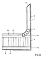
- Fig. 6a shows an embodiment in which although a part of the end portion 4 of the cover layers 1a, 1b, here the upper cover layer 1a, extends at an angle to the longitudinal planes Ea, Eb. However, this time the part of the end portion 4 is not down, but led upwards.
- the narrow surface 3 and the parallel to the narrow side of the upper cover layer 1a is supported and covered by a leg of a profile 15, wherein another leg of the profile 15 is connected to the underside of the lower cover layer 1b. Also in this case the outer sides of the cover layers 1a, 1b are coated.
- As a cross-sectional weakening further slots 8 are provided in a part of the end portion 4.
- Such a lightweight board can be used for example as a kitchen worktop, wherein the end portion with the upwardly extending end portion 4 serves as the end strip and wall connection.
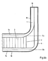
- Fig. 6b shows a similar variant in which also a part of the end portion 4 of the cover layers 1a, 1b, here the upper cover layer 1b, runs at an angle to the longitudinal planes Ea, Eb and is guided upward.
- no profile is used here in support of the upwardly guided cover layer 1b and to cover the narrow surface 3, but it is the other of the two cover layers, namely the lower cover layer 1a, also guided upwards and parallel to the cover layer 1b.
- a cross-sectional weakening here is a partial tapering of the cross section of the two cover layers 1a, 1b is provided.
- the two parallel parts of the cover layers 1a, 1b are glued together and thus also form a suitable for a kitchen worktop end bar and a corresponding wall outlet.
- FIG. 7 Finally, the possibility is shown, adjacent edges that meet in a corner of the lightweight board, here a kitchen worktop, perpendicular to each other, to produce by the inventive method.
- This will, as in Fig. 7a ) is shown in a plan view of the lightweight board, to be formed cover layer 1a in the region of the later corner 18 with a notch 17, as well as in the region of the two later edges each provided with an exposed end portion 4.
- the two end sections 4 are then, as described with reference to the preceding figures, so guided over the respective narrow surface (not shown) and fixed, that two stable edges and a corresponding corner 18 arise ( Fig. 7b )).
Landscapes
- Engineering & Computer Science (AREA)
- Architecture (AREA)
- Civil Engineering (AREA)
- Structural Engineering (AREA)
- Manufacturing & Machinery (AREA)
- Laminated Bodies (AREA)
Priority Applications (1)
| Application Number | Priority Date | Filing Date | Title |
|---|---|---|---|
| PL07787906T PL2051848T3 (pl) | 2006-08-14 | 2007-07-25 | Lekka płyta konstrukcyjna |
Applications Claiming Priority (2)
| Application Number | Priority Date | Filing Date | Title |
|---|---|---|---|
| DE102006038115.7A DE102006038115B4 (de) | 2006-08-14 | 2006-08-14 | Leichtbauplatte und Verfahren zu deren Herstellung |
| PCT/EP2007/057680 WO2008019929A1 (de) | 2006-08-14 | 2007-07-25 | Leichtbauplatte |
Publications (2)
| Publication Number | Publication Date |
|---|---|
| EP2051848A1 EP2051848A1 (de) | 2009-04-29 |
| EP2051848B1 true EP2051848B1 (de) | 2012-03-21 |
Family
ID=38815737
Family Applications (1)
| Application Number | Title | Priority Date | Filing Date |
|---|---|---|---|
| EP07787906A Active EP2051848B1 (de) | 2006-08-14 | 2007-07-25 | Leichtbauplatte |
Country Status (5)
| Country | Link |
|---|---|
| EP (1) | EP2051848B1 (pl) |
| AT (1) | ATE550174T1 (pl) |
| DE (1) | DE102006038115B4 (pl) |
| PL (1) | PL2051848T3 (pl) |
| WO (1) | WO2008019929A1 (pl) |
Families Citing this family (8)
| Publication number | Priority date | Publication date | Assignee | Title |
|---|---|---|---|---|
| EP2136010A1 (en) * | 2008-06-17 | 2009-12-23 | Rockwool International A/S | A building system for a building structure |
| DE102008034828B4 (de) * | 2008-07-22 | 2010-05-12 | Flooring Technologies Ltd. | Beschichtete dekorative Trägerplatte (DPL) mit Biegekante und Verfahren zur Herstellung der beschichteten Trägerplatte |
| ES2376949T3 (es) | 2008-09-18 | 2012-03-21 | Homag Holzbearbeitungssysteme Ag | Procedimiento para el acabado de piezas de trabajo en forma de plancha |
| DE102009005316A1 (de) | 2009-01-16 | 2010-07-22 | Fritz Egger Gmbh & Co. | Bauteil, insbesondere Leichtbauplatte |
| DE102011015195B4 (de) * | 2011-03-25 | 2012-12-27 | Fritz Egger Gmbh & Co. Og | Verfahren und Vorrichtung zum Bekanten von Holzwerkstoffplatten sowie Holzwerkstoffplatten |
| DE102013016998A1 (de) * | 2013-10-14 | 2015-04-16 | Faurecia Innenraum Systeme Gmbh | Verfahren und Vorrichtung zur Herstellung eines Verkleidungsteils |
| DE102015000393A1 (de) | 2014-01-21 | 2015-07-23 | Frank Becher | Verfahren zur Herstellung von geschlossen-porigen Erzeugnissen mit hohlen Zellen, mittels dessen der Druck in den Zellen kontrolliert während des Aufschäumens erhöht oder reduziert werden kann, sowie Erzeugnisse, die nach diesem Verfahren hergestellt werden |
| DE102024127022A1 (de) | 2024-09-19 | 2026-03-19 | REHAU Industries SE & Co. KG | Verfahren zur Schmalflächenbeschichtung eines Plattenelementes |
Citations (1)
| Publication number | Priority date | Publication date | Assignee | Title |
|---|---|---|---|---|
| DE3046317A1 (de) * | 1980-12-09 | 1982-07-01 | Egon 4200 Oberhausen Küper | Bauelement fuer den bau- und den moebelbedarf |
Family Cites Families (14)
| Publication number | Priority date | Publication date | Assignee | Title |
|---|---|---|---|---|
| DE2129828A1 (de) | 1933-11-08 | 1973-01-04 | Gruber & Weber | Verfahren zur herstellung von verformten werkstuecken aus vorgefertigten, beschichteten spanplatten |
| US2839442A (en) * | 1955-02-23 | 1958-06-17 | Smith Corp A O | Process of making a lightweight structural panel |
| DE7304666U (de) | 1973-02-08 | 1975-02-27 | Rottmann H Elementbau Gmbh | Holzplatte mit einer oder mehreren abgerundeten Kanten oder Flächen |
| JPS5154608A (en) * | 1974-11-07 | 1976-05-13 | Taku Yamada | Setsukoboodono seizohoho |
| US4327146A (en) * | 1980-10-27 | 1982-04-27 | National Gypsum Company | High density interface gypsum board and method for making same |
| DE8128714U1 (de) * | 1981-10-01 | 1982-02-04 | Resopal-Werk H. Römmler GmbH, 6800 Mannheim | "verbundelement" |
| DE3742008C2 (de) | 1987-12-11 | 1996-06-13 | Westag & Getalit Ag | Verfahren zur Herstellung einer Arbeitsplatte und Arbeitsplatte |
| DE3906594A1 (de) | 1988-11-19 | 1990-05-23 | Gruber & Weber Gmbh Co Kg | Verfahren zur herstellung eines postforming-laminats |
| US5006391A (en) * | 1989-10-23 | 1991-04-09 | Biersach James R | Honeycomb structure and method of making same |
| ITPD20020090A1 (it) | 2002-04-11 | 2003-10-13 | Quadrifoglio Di Paola Cozza E | Struttura di pannello tamburato |
| DE10313055B4 (de) * | 2003-03-24 | 2006-12-28 | Homag Holzbearbeitungssysteme Ag | Verfahren und Vorrichtung zur Herstellung einer Leichtbauplatte |
| CN2647125Y (zh) * | 2003-10-08 | 2004-10-13 | 冷鹭浩 | 一种蜂窝纸内芯封边倒吸塑桌面板 |
| DE202004001892U1 (de) * | 2004-01-09 | 2004-06-03 | Cammisar, Hartmut | Mehrebenenplatte |
| DE102004053881B4 (de) | 2004-11-04 | 2008-11-13 | Ima Klessmann Gmbh Holzbearbeitungssysteme | Verfahren zum Fertigen von formatierten Leichtbauplatten |
-
2006
- 2006-08-14 DE DE102006038115.7A patent/DE102006038115B4/de not_active Expired - Fee Related
-
2007
- 2007-07-25 PL PL07787906T patent/PL2051848T3/pl unknown
- 2007-07-25 WO PCT/EP2007/057680 patent/WO2008019929A1/de not_active Ceased
- 2007-07-25 AT AT07787906T patent/ATE550174T1/de active
- 2007-07-25 EP EP07787906A patent/EP2051848B1/de active Active
Patent Citations (1)
| Publication number | Priority date | Publication date | Assignee | Title |
|---|---|---|---|---|
| DE3046317A1 (de) * | 1980-12-09 | 1982-07-01 | Egon 4200 Oberhausen Küper | Bauelement fuer den bau- und den moebelbedarf |
Also Published As
| Publication number | Publication date |
|---|---|
| WO2008019929A1 (de) | 2008-02-21 |
| DE102006038115B4 (de) | 2019-01-24 |
| DE102006038115A1 (de) | 2008-02-21 |
| EP2051848A1 (de) | 2009-04-29 |
| ATE550174T1 (de) | 2012-04-15 |
| PL2051848T3 (pl) | 2012-08-31 |
Similar Documents
| Publication | Publication Date | Title |
|---|---|---|
| EP2051848B1 (de) | Leichtbauplatte | |
| DE69312927T2 (de) | Platte und verfahren zu ihrer herstellung | |
| EP2834526A1 (de) | Leichtbauplatte, verbindungsanordnung und verfahren zum herstellen einer verbindungsanordnung | |
| EP2015652B1 (de) | Zusatzelement für ein möbelteil aus einer leichtbauplatte, möbelteil und möbel | |
| EP2016237B1 (de) | Abdichtungselement für eine leichtbauplatte | |
| EP1881124A2 (de) | Leichtbauplatte | |
| EP2027349B1 (de) | Verfahren zum herstellen einer leichtbauplatte mit riegelverklebung | |
| EP2379321B1 (de) | Bauteil, insbesondere leichtbauplatte | |
| EP2468495B1 (de) | Im randbereich verstärkte sandwichplatte, verstärkungselement und verfahren zur herstellung einer im randbereich verstärkten sandwichplatte | |
| EP2525010B1 (de) | Leichtbauplatte, Verfahren und Vorrichtung zur Herstellung dieser Leichtbauplatte | |
| EP0864020A2 (de) | Verfahren zum herstellen von bambus enthaltenden bauteilen, insbesondere von für möbel und innenausbau verarbeitbaren bambusleimplatten, und bauteile aus bambus | |
| EP1992759B1 (de) | Leichtbauplatte sowie Verfahren zur Herstellung einer Leichtbauplatte. | |
| EP2147778B1 (de) | Leichtbauplatte für den Möbelbau | |
| EP2403712B1 (de) | Leichtbauplatte sowie verfahren und vorrichtung zu deren herstellung | |
| DE29610829U1 (de) | Bauelement | |
| DE4337474A1 (de) | Türblattaufbau | |
| DE102017001477B4 (de) | Arbeitsplatte | |
| EP2589738A2 (de) | Decklage aus Holz für Fenster, Türen und Fassadenkomponenten und Verfahren zu deren Herstellung | |
| DE9316796U1 (de) | Türblattaufbau | |
| DE102019001601A1 (de) | Leichtbauplatte | |
| DE29812223U1 (de) | Leichtbauplatte | |
| DE29923684U1 (de) | Rahmenholm einer Glasrahmenkonstruktion für Brandschutzverglasungen |
Legal Events
| Date | Code | Title | Description |
|---|---|---|---|
| PUAI | Public reference made under article 153(3) epc to a published international application that has entered the european phase |
Free format text: ORIGINAL CODE: 0009012 |
|
| 17P | Request for examination filed |
Effective date: 20081031 |
|
| AK | Designated contracting states |
Kind code of ref document: A1 Designated state(s): AT BE BG CH CY CZ DE DK EE ES FI FR GB GR HU IE IS IT LI LT LU LV MC MT NL PL PT RO SE SI SK TR |
|
| AX | Request for extension of the european patent |
Extension state: AL BA HR MK RS |
|
| 17Q | First examination report despatched |
Effective date: 20090724 |
|
| RAP1 | Party data changed (applicant data changed or rights of an application transferred) |
Owner name: FRITZ EGGER GMBH & CO. OG |
|
| GRAP | Despatch of communication of intention to grant a patent |
Free format text: ORIGINAL CODE: EPIDOSNIGR1 |
|
| DAX | Request for extension of the european patent (deleted) | ||
| GRAS | Grant fee paid |
Free format text: ORIGINAL CODE: EPIDOSNIGR3 |
|
| GRAA | (expected) grant |
Free format text: ORIGINAL CODE: 0009210 |
|
| AK | Designated contracting states |
Kind code of ref document: B1 Designated state(s): AT BE BG CH CY CZ DE DK EE ES FI FR GB GR HU IE IS IT LI LT LU LV MC MT NL PL PT RO SE SI SK TR |
|
| REG | Reference to a national code |
Ref country code: GB Ref legal event code: FG4D Free format text: NOT ENGLISH |
|
| REG | Reference to a national code |
Ref country code: CH Ref legal event code: EP Ref country code: CH Ref legal event code: NV Representative=s name: TROESCH SCHEIDEGGER WERNER AG |
|
| REG | Reference to a national code |
Ref country code: IE Ref legal event code: FG4D Free format text: LANGUAGE OF EP DOCUMENT: GERMAN |
|
| REG | Reference to a national code |
Ref country code: AT Ref legal event code: REF Ref document number: 550174 Country of ref document: AT Kind code of ref document: T Effective date: 20120415 |
|
| REG | Reference to a national code |
Ref country code: DE Ref legal event code: R096 Ref document number: 502007009530 Country of ref document: DE Effective date: 20120510 |
|
| REG | Reference to a national code |
Ref country code: RO Ref legal event code: EPE |
|
| REG | Reference to a national code |
Ref country code: NL Ref legal event code: VDEP Effective date: 20120321 |
|
| PG25 | Lapsed in a contracting state [announced via postgrant information from national office to epo] |
Ref country code: LV Free format text: LAPSE BECAUSE OF FAILURE TO SUBMIT A TRANSLATION OF THE DESCRIPTION OR TO PAY THE FEE WITHIN THE PRESCRIBED TIME-LIMIT Effective date: 20120321 Ref country code: FI Free format text: LAPSE BECAUSE OF FAILURE TO SUBMIT A TRANSLATION OF THE DESCRIPTION OR TO PAY THE FEE WITHIN THE PRESCRIBED TIME-LIMIT Effective date: 20120321 Ref country code: GR Free format text: LAPSE BECAUSE OF FAILURE TO SUBMIT A TRANSLATION OF THE DESCRIPTION OR TO PAY THE FEE WITHIN THE PRESCRIBED TIME-LIMIT Effective date: 20120622 |
|
| REG | Reference to a national code |
Ref country code: PL Ref legal event code: T3 |
|
| PG25 | Lapsed in a contracting state [announced via postgrant information from national office to epo] |
Ref country code: CY Free format text: LAPSE BECAUSE OF FAILURE TO SUBMIT A TRANSLATION OF THE DESCRIPTION OR TO PAY THE FEE WITHIN THE PRESCRIBED TIME-LIMIT Effective date: 20120321 |
|
| PG25 | Lapsed in a contracting state [announced via postgrant information from national office to epo] |
Ref country code: SE Free format text: LAPSE BECAUSE OF FAILURE TO SUBMIT A TRANSLATION OF THE DESCRIPTION OR TO PAY THE FEE WITHIN THE PRESCRIBED TIME-LIMIT Effective date: 20120321 Ref country code: IS Free format text: LAPSE BECAUSE OF FAILURE TO SUBMIT A TRANSLATION OF THE DESCRIPTION OR TO PAY THE FEE WITHIN THE PRESCRIBED TIME-LIMIT Effective date: 20120721 Ref country code: EE Free format text: LAPSE BECAUSE OF FAILURE TO SUBMIT A TRANSLATION OF THE DESCRIPTION OR TO PAY THE FEE WITHIN THE PRESCRIBED TIME-LIMIT Effective date: 20120321 Ref country code: SI Free format text: LAPSE BECAUSE OF FAILURE TO SUBMIT A TRANSLATION OF THE DESCRIPTION OR TO PAY THE FEE WITHIN THE PRESCRIBED TIME-LIMIT Effective date: 20120321 |
|
| PG25 | Lapsed in a contracting state [announced via postgrant information from national office to epo] |
Ref country code: SK Free format text: LAPSE BECAUSE OF FAILURE TO SUBMIT A TRANSLATION OF THE DESCRIPTION OR TO PAY THE FEE WITHIN THE PRESCRIBED TIME-LIMIT Effective date: 20120321 Ref country code: PT Free format text: LAPSE BECAUSE OF FAILURE TO SUBMIT A TRANSLATION OF THE DESCRIPTION OR TO PAY THE FEE WITHIN THE PRESCRIBED TIME-LIMIT Effective date: 20120723 |
|
| PLBE | No opposition filed within time limit |
Free format text: ORIGINAL CODE: 0009261 |
|
| STAA | Information on the status of an ep patent application or granted ep patent |
Free format text: STATUS: NO OPPOSITION FILED WITHIN TIME LIMIT |
|
| BERE | Be: lapsed |
Owner name: FRITZ EGGER GMBH & CO. OG Effective date: 20120731 |
|
| PG25 | Lapsed in a contracting state [announced via postgrant information from national office to epo] |
Ref country code: DK Free format text: LAPSE BECAUSE OF FAILURE TO SUBMIT A TRANSLATION OF THE DESCRIPTION OR TO PAY THE FEE WITHIN THE PRESCRIBED TIME-LIMIT Effective date: 20120321 Ref country code: NL Free format text: LAPSE BECAUSE OF FAILURE TO SUBMIT A TRANSLATION OF THE DESCRIPTION OR TO PAY THE FEE WITHIN THE PRESCRIBED TIME-LIMIT Effective date: 20120321 |
|
| 26N | No opposition filed |
Effective date: 20130102 |
|
| PG25 | Lapsed in a contracting state [announced via postgrant information from national office to epo] |
Ref country code: MC Free format text: LAPSE BECAUSE OF NON-PAYMENT OF DUE FEES Effective date: 20120731 |
|
| REG | Reference to a national code |
Ref country code: DE Ref legal event code: R097 Ref document number: 502007009530 Country of ref document: DE Effective date: 20130102 |
|
| PG25 | Lapsed in a contracting state [announced via postgrant information from national office to epo] |
Ref country code: ES Free format text: LAPSE BECAUSE OF FAILURE TO SUBMIT A TRANSLATION OF THE DESCRIPTION OR TO PAY THE FEE WITHIN THE PRESCRIBED TIME-LIMIT Effective date: 20120702 |
|
| REG | Reference to a national code |
Ref country code: IE Ref legal event code: MM4A |
|
| PG25 | Lapsed in a contracting state [announced via postgrant information from national office to epo] |
Ref country code: BE Free format text: LAPSE BECAUSE OF NON-PAYMENT OF DUE FEES Effective date: 20120731 |
|
| PG25 | Lapsed in a contracting state [announced via postgrant information from national office to epo] |
Ref country code: MT Free format text: LAPSE BECAUSE OF FAILURE TO SUBMIT A TRANSLATION OF THE DESCRIPTION OR TO PAY THE FEE WITHIN THE PRESCRIBED TIME-LIMIT Effective date: 20120321 Ref country code: IE Free format text: LAPSE BECAUSE OF NON-PAYMENT OF DUE FEES Effective date: 20120725 Ref country code: BG Free format text: LAPSE BECAUSE OF FAILURE TO SUBMIT A TRANSLATION OF THE DESCRIPTION OR TO PAY THE FEE WITHIN THE PRESCRIBED TIME-LIMIT Effective date: 20120621 |
|
| PG25 | Lapsed in a contracting state [announced via postgrant information from national office to epo] |
Ref country code: LU Free format text: LAPSE BECAUSE OF NON-PAYMENT OF DUE FEES Effective date: 20120725 |
|
| PG25 | Lapsed in a contracting state [announced via postgrant information from national office to epo] |
Ref country code: HU Free format text: LAPSE BECAUSE OF FAILURE TO SUBMIT A TRANSLATION OF THE DESCRIPTION OR TO PAY THE FEE WITHIN THE PRESCRIBED TIME-LIMIT Effective date: 20070725 |
|
| REG | Reference to a national code |
Ref country code: FR Ref legal event code: PLFP Year of fee payment: 10 |
|
| REG | Reference to a national code |
Ref country code: FR Ref legal event code: PLFP Year of fee payment: 11 |
|
| REG | Reference to a national code |
Ref country code: FR Ref legal event code: PLFP Year of fee payment: 12 |
|
| PGFP | Annual fee paid to national office [announced via postgrant information from national office to epo] |
Ref country code: RO Payment date: 20220629 Year of fee payment: 16 Ref country code: LT Payment date: 20220616 Year of fee payment: 16 Ref country code: CZ Payment date: 20220624 Year of fee payment: 16 |
|
| PGFP | Annual fee paid to national office [announced via postgrant information from national office to epo] |
Ref country code: TR Payment date: 20220618 Year of fee payment: 16 Ref country code: PL Payment date: 20220617 Year of fee payment: 16 |
|
| PGFP | Annual fee paid to national office [announced via postgrant information from national office to epo] |
Ref country code: IT Payment date: 20220721 Year of fee payment: 16 Ref country code: GB Payment date: 20220721 Year of fee payment: 16 Ref country code: DE Payment date: 20220720 Year of fee payment: 16 Ref country code: AT Payment date: 20220721 Year of fee payment: 16 |
|
| PGFP | Annual fee paid to national office [announced via postgrant information from national office to epo] |
Ref country code: FR Payment date: 20220720 Year of fee payment: 16 |
|
| PGFP | Annual fee paid to national office [announced via postgrant information from national office to epo] |
Ref country code: CH Payment date: 20220725 Year of fee payment: 16 |
|
| REG | Reference to a national code |
Ref country code: DE Ref legal event code: R119 Ref document number: 502007009530 Country of ref document: DE |
|
| REG | Reference to a national code |
Ref country code: LT Ref legal event code: MM4D Effective date: 20230725 |
|
| REG | Reference to a national code |
Ref country code: CH Ref legal event code: PL |
|
| REG | Reference to a national code |
Ref country code: AT Ref legal event code: MM01 Ref document number: 550174 Country of ref document: AT Kind code of ref document: T Effective date: 20230725 |
|
| GBPC | Gb: european patent ceased through non-payment of renewal fee |
Effective date: 20230725 |
|
| PG25 | Lapsed in a contracting state [announced via postgrant information from national office to epo] |
Ref country code: LT Free format text: LAPSE BECAUSE OF NON-PAYMENT OF DUE FEES Effective date: 20230725 |
|
| PG25 | Lapsed in a contracting state [announced via postgrant information from national office to epo] |
Ref country code: AT Free format text: LAPSE BECAUSE OF NON-PAYMENT OF DUE FEES Effective date: 20230725 |
|
| PG25 | Lapsed in a contracting state [announced via postgrant information from national office to epo] |
Ref country code: RO Free format text: LAPSE BECAUSE OF NON-PAYMENT OF DUE FEES Effective date: 20230725 Ref country code: LT Free format text: LAPSE BECAUSE OF NON-PAYMENT OF DUE FEES Effective date: 20230725 Ref country code: DE Free format text: LAPSE BECAUSE OF NON-PAYMENT OF DUE FEES Effective date: 20240201 Ref country code: CZ Free format text: LAPSE BECAUSE OF NON-PAYMENT OF DUE FEES Effective date: 20230725 Ref country code: AT Free format text: LAPSE BECAUSE OF NON-PAYMENT OF DUE FEES Effective date: 20230725 Ref country code: GB Free format text: LAPSE BECAUSE OF NON-PAYMENT OF DUE FEES Effective date: 20230725 Ref country code: CH Free format text: LAPSE BECAUSE OF NON-PAYMENT OF DUE FEES Effective date: 20230731 |
|
| PG25 | Lapsed in a contracting state [announced via postgrant information from national office to epo] |
Ref country code: FR Free format text: LAPSE BECAUSE OF NON-PAYMENT OF DUE FEES Effective date: 20230731 |
|
| PG25 | Lapsed in a contracting state [announced via postgrant information from national office to epo] |
Ref country code: IT Free format text: LAPSE BECAUSE OF NON-PAYMENT OF DUE FEES Effective date: 20230725 |
|
| PG25 | Lapsed in a contracting state [announced via postgrant information from national office to epo] |
Ref country code: PL Free format text: LAPSE BECAUSE OF NON-PAYMENT OF DUE FEES Effective date: 20230725 |
|
| PG25 | Lapsed in a contracting state [announced via postgrant information from national office to epo] |
Ref country code: PL Free format text: LAPSE BECAUSE OF NON-PAYMENT OF DUE FEES Effective date: 20230725 |