EP2050358A2 - Auszugsführung - Google Patents
Auszugsführung Download PDFInfo
- Publication number
- EP2050358A2 EP2050358A2 EP08162965A EP08162965A EP2050358A2 EP 2050358 A2 EP2050358 A2 EP 2050358A2 EP 08162965 A EP08162965 A EP 08162965A EP 08162965 A EP08162965 A EP 08162965A EP 2050358 A2 EP2050358 A2 EP 2050358A2
- Authority
- EP
- European Patent Office
- Prior art keywords
- rail
- end stop
- pull
- rails
- guide according
- Prior art date
- Legal status (The legal status is an assumption and is not a legal conclusion. Google has not performed a legal analysis and makes no representation as to the accuracy of the status listed.)
- Granted
Links
Images



Classifications
-
- A—HUMAN NECESSITIES
- A47—FURNITURE; DOMESTIC ARTICLES OR APPLIANCES; COFFEE MILLS; SPICE MILLS; SUCTION CLEANERS IN GENERAL
- A47B—TABLES; DESKS; OFFICE FURNITURE; CABINETS; DRAWERS; GENERAL DETAILS OF FURNITURE
- A47B88/00—Drawers for tables, cabinets or like furniture; Guides for drawers
- A47B88/40—Sliding drawers; Slides or guides therefor
- A47B88/49—Sliding drawers; Slides or guides therefor with double extensible guides or parts
- A47B88/493—Sliding drawers; Slides or guides therefor with double extensible guides or parts with rollers, ball bearings, wheels, or the like
-
- A—HUMAN NECESSITIES
- A47—FURNITURE; DOMESTIC ARTICLES OR APPLIANCES; COFFEE MILLS; SPICE MILLS; SUCTION CLEANERS IN GENERAL
- A47B—TABLES; DESKS; OFFICE FURNITURE; CABINETS; DRAWERS; GENERAL DETAILS OF FURNITURE
- A47B2210/00—General construction of drawers, guides and guide devices
- A47B2210/0002—Guide construction for drawers
- A47B2210/0018—Buffers, stop blocks or latches for single drawer slides
-
- A—HUMAN NECESSITIES
- A47—FURNITURE; DOMESTIC ARTICLES OR APPLIANCES; COFFEE MILLS; SPICE MILLS; SUCTION CLEANERS IN GENERAL
- A47B—TABLES; DESKS; OFFICE FURNITURE; CABINETS; DRAWERS; GENERAL DETAILS OF FURNITURE
- A47B2210/00—General construction of drawers, guides and guide devices
- A47B2210/0002—Guide construction for drawers
- A47B2210/0029—Guide bearing means
- A47B2210/0032—Balls
-
- A—HUMAN NECESSITIES
- A47—FURNITURE; DOMESTIC ARTICLES OR APPLIANCES; COFFEE MILLS; SPICE MILLS; SUCTION CLEANERS IN GENERAL
- A47B—TABLES; DESKS; OFFICE FURNITURE; CABINETS; DRAWERS; GENERAL DETAILS OF FURNITURE
- A47B2210/00—General construction of drawers, guides and guide devices
- A47B2210/0002—Guide construction for drawers
- A47B2210/0051—Guide position
- A47B2210/0059—Guide located at the side of the drawer
Definitions
- the present invention relates to a drawer slide, in particular for drawers, with a fixable on the furniture body guide rail, a movable drawer rail and preferably a center rail between drawer rail and guide rail, wherein the rails are mounted on rolling elements relative to each other movable and on the rails a plurality of WälzSystembahnen are formed the extension movement of the rails are limited by elastic end stops.
- a pull-out guide in which a guide rail to a furniture body can be fixed and to which a center rail and a pull-out rail are movably mounted.
- an elastic end stop is provided, which is mounted in a rectangular recess of the pull-out rail.
- a web of the stopper passes through the recess to secure the stopper.
- the installation of such a stop is relatively expensive, since the web and the recess must be made accurately.
- the forces acting on the web are partially high, so that there is a risk that the arranged in the receptacle web dissolves and the stop is ineffective.
- At least one end stop is inserted at a slot of a rail and held by latching means on the rail.
- the end stop can be plugged onto the rail in a simple manner from the outside, with a securing in the longitudinal direction of the rail via the slot.
- the abutment surface mounted on the rail can be made comparatively large and the forces when striking a rail are better distributed.
- the end stop surrounds the rail at least partially.
- the end stop may be arranged adjacent to the WälzSystembahnen a rail.
- the stop can therefore be used to limit the travel of a WälzSystemhimfigs so that it runs onto the end stop and thus limits the travel of a rail.
- the end stop is substantially positively against the WälzSystembahnen, so that the end stop is securely held on the rail.
- the abutment surface may be aligned perpendicular to a longitudinal direction of the rail to avoid lateral forces.
- the end stop on a first U-shaped portion with legs which engage around a rail, and a second U-shaped portion, wherein at least partially a material filling is provided between the legs, in a slot the rail is inserted.
- the material filling then relies on the occurrence of impact forces in the slot, so that only compressive forces are transmitted, but not the end stop loading torque.
- one or more projections for locking on the rail are provided on the end stop, so that an accidental release is avoided.
- the end stop is preferably made of an elastomeric material.
- the drawer guide on a middle rail, which has on opposite sides of an end stop for limiting the travel relative to the guide rail and the drawer rail.
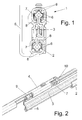
- a pullout guide 1 comprises a guide rail 2, which can be fixed at an angle 5 to a furniture carcass.
- a middle rail 3 is movably mounted, which is coupled to a pull-out rail on which a drawer is mounted.
- the pull-out rail 4 and the guide rail 2 are constructed substantially square in cross-section and each have on the sides facing each other a slot in the longitudinal direction, through which a web of the middle rail 3 is inserted.
- a cross-sectionally substantially diamond-shaped projection is arranged within the guide rail 2 and the pull-out rail 4, on the curved Wälz restructuringbahnen 6 are provided.
- rolling elements balls are preferably used, which bear against the inner WälzConsequentlybahnen 6 of the middle rail 3 and the outer WälzConsequentlybahnen 8, which are formed at the four corner regions of the guide rail 2 and the drawer rail 4.
- the rolling elements can be accommodated in a cage 7.
- FIG. 2 there is an elastic end stop 9 on the center rail 3 within the drawer rail 4.
- the arranged in the drawer rail 4 recess is shown only for a better clarity.
- a further end stop 10 is also mounted on the drawer rail 4.
- the assembly of the end stop 9 is in the FIGS. 3A to 3C shown.
- the middle rail 3 is located on an upper side a perpendicular to the longitudinal direction aligned slot 11 which is recessed in the strip-shaped projection with the four WälzSystembahnen 6.
- the end stop 9 is partially inserted and is thus not displaced in a longitudinal direction.
- 9 locking means are provided on the end stop, so that it is securely held on the center rail 3.
- end stop 9 can of course also be mounted on the lower projection within the guide rail 2.
- the end stop 9 is made of an elastomeric material and has a first U-shaped portion with legs 13, between which a slot 12 is recessed. On the legs 13, an inwardly directed bulge 14 is provided, which is arranged adjacent to the WälzSystembahnen 6 and can also rest positively or with little play on the WälzSystembahnen 6. Further, further bulges 15 are provided on the first U-shaped portion in the bottom region, which are arranged adjacent to a Wälz Eisenbahn 6. Therefore, this first U-shaped portion surrounds the lower or upper projection of the center rail 3 such that the end stop 9 can be latched to the center rail 3.
- the end stop 9 further includes a second U-shaped portion having two spaced legs 13 at which bulges 14 are formed as in the first U-shaped portion. Unlike the first U-shaped section, however, a material filling 16 is arranged between the legs, which terminates with a flat edge 17. This material filling 16 can be inserted into the slot 11 and serves to fix the end stop 9 in the longitudinal direction.
- FIG. 6 a modified end stop 10 is shown mounted on the pull-out rail 4.
- the end stop 10 serves to limit the travel of a rolling element cage 7, which is arranged between the pull-out rail 4 and the middle rail 3.
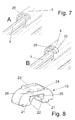
- FIGS. 7A and 7B the assembly steps for the end stop 10 are shown.
- a perpendicular aligned to the longitudinal direction of the rail slot 20 is recessed at the top, which is rectangular in shape and in which the end stop 10 can be inserted from the outside.
- the end stop 10 can be latched to the pull-out rail 4, wherein abutment forces are removed on the walls of the elongated slot 20.
- the end stop 10 comprises a lower channel with bulges 22, which are each arranged adjacent to a curved Wälz Eisenbahn 6.
- a projection 25 is provided laterally, which is inserted within the pull-out rail 4.
- a plate 23 is formed on the upper side, which has a strip-shaped projection 24 which engages over the pull-out rail 4, so that the material of the pull-out rail 4 is held in a region between the projection 25 and the projection 24 in a receptacle 26.
- the end stop 10 can only be removed from the pull-out rail 4 when the latching forces are overcome by the projection 25.
- FIG. 9 the end stop 10 is shown in the assembled position.
- the end stop engages with the curved surfaces 22 on the legs 21 in the drawer rail 4 and forms a stop on a side surface.
- a step 27 is formed on opposite sides of the legs 21, which is supported on the pull-4. This allows the end stop 10 both in one Longitudinal direction of the drawer rail 4 and are not moved perpendicular thereto.
- the two end stops 9 and 10 can be installed both once and several times in a pull-out guide according to the invention.
- the end stops 9 and 10 may be provided where a rolling element cage 7 could otherwise impact a metallic abutment.
Landscapes
- Drawers Of Furniture (AREA)
- Bearings For Parts Moving Linearly (AREA)
Abstract
Description
- Die vorliegende Erfindung betrifft eine Auszugsführung, insbesondere für Schubkästen, mit einer am Möbelkorpus festlegbaren Führungsschiene, einer verfahrbaren Auszugsschiene und vorzugsweise einer Mittelschiene zwischen Auszugsschiene und Führungsschiene, wobei die Schienen über Wälzkörper relativ zueinander verfahrbar gelagert sind und an den Schienen mehrere Wälzkörperbahnen ausgebildet sind, wobei die Auszugsbewegung der Schienen durch elastische Endanschläge begrenzt sind.
- Aus der
US 4469384 ist eine Auszugsführung bekannt, bei der eine Führungsschiene an einem Möbelkorpus festlegbar ist und an der eine Mittelschiene und eine Auszugsschiene verfahrbar gelagert sind. Zur Begrenzung des Verfahrweges der Auszugsschiene ist ein elastischer Endanschlag vorgesehen, der in einer rechteckigen Aussparung der Auszugsschiene montiert ist. Dabei durchgreift ein Steg des Anschlages die Aussparung, um den Anschlag zu befestigen. Die Montage eines solchen Anschlages ist vergleichsweise aufwendig, da der Steg und die Aussparung passgenau hergestellt werden müssen. Zudem sind die auf den Steg wirkenden Kräfte teilweise hoch, so dass die Gefahr besteht, dass der in der Aufnahme angeordnete Steg sich löst und der Anschlag wirkungslos wird. - Es ist daher Aufgabe der vorliegenden Erfindung eine Auszugsführung zu schaffen, bei der ein Endanschlag leicht zu montieren ist und auch dauerhaft Anschlagskräfte aufnehmen kann.
- Diese Aufgabe wird mit einer Auszugsführung mit den Merkmalen des Anspruches 1 gelöst.
- Erfindungsgemäß ist mindestens ein Endanschlag an einem Schlitz einer Schiene eingefügt und über Rastmittel an der Schiene gehalten. Dadurch kann der Endanschlag auf einfache Weise von außen auf die Schiene aufgesteckt werden, wobei eine Sicherung in Längsrichtung der Schiene über den Schlitz erfolgt. Dadurch kann die an der Schiene gelagerte Anschlagsfläche vergleichsweise groß ausgebildet sein und die Kräfte beim Anschlagen einer Schiene werden besser verteilt. Durch Verrasten des Endanschlages an der Schiene über die Rastmittel ist die Montage zudem sehr einfach.
- Vorzugsweise umgreift der Endanschlag die Schiene zumindest teilweise. Dabei kann der Endanschlag benachbart zu den Wälzkörperbahnen einer Schiene angeordnet sein. Der Anschlag kann daher zum Begrenzen des Verfahrweges eines Wälzkörperkäfigs eingesetzt werden, so dass dieser auf den Endanschlag aufläuft und so den Verfahrweg einer Schiene begrenzt. Vorzugsweise liegt der Endanschlag im Wesentlichen formschlüssig an den Wälzkörperbahnen an, so dass der Endanschlag sicher an der Schiene gehalten ist. Die Anschlagsfläche kann dabei senkrecht zu einer Längsrichtung der Schiene ausgerichtet sein um Querkräfte zu vermeiden.
- Gemäß einer weiteren Ausgestaltung der Erfindung weist der Endanschlag einen ersten U-förmigen Abschnitt mit Schenkeln auf, die eine Schiene umgreifen, und einen zweiten U-förmigen Abschnitt auf, bei dem zwischen den Schenkeln zumindest teilweise eine Materialfüllung vorgesehen ist, die in einen Schlitz an der Schiene eingefügt ist. Die Materialfüllung stützt sich bei Auftreten von Anschlagskräften dann in dem Schlitz ab, so dass nur Druckkräfte übertragen werden, aber kein den Endanschlag belastendes Drehmoment.
- Für einen besonderst guten Halt des Endanschlages kann dieser klemmend an dem Schlitz der Schiene festgelegt sein.
- Vorzugsweise sind an dem Endanschlag ein oder mehrere Vorsprünge zum Verrasten an der Schiene vorgesehen, so dass ein versehentliches Lösen vermieden wird.
- Für eine ausreichende Dämpfung besteht der Endanschlag vorzugsweise aus einem Elastomermaterial.
- Gemäß einer weiteren Ausgestaltung der Erfindung weist die Auszugsführung eine Mittelschiene auf, die an gegenüberliegenden Seiten einen Endanschlag zur Begrenzung des Verfahrweges gegenüber der Führungsschiene und der Auszugsschiene aufweist. Dadurch wird ein lautes Anschlaggeräusch sicher vermieden, da die Schienen untereinander jeweils durch Endanschläge gedämpft sind.
- Die Erfindung wird nachfolgend anhand mehrerer Ausführungsbeispiele mit Bezug auf die beigefügten Zeichnungen näher erläutert. Es zeigen:
- Figur 1
- eine Schnittansicht auf ein erfindungsgemäßes Ausfüh- rungsbeispiel einer Auszugsführung;
- Figur 2
- eine perspektivische Ansicht der Auszugsführung der
Figur 1 , teilweise im Schnitt; - Figur 3A bis 3C
- mehrere Detailansichten der Auszugsführung der
Figur 1 bei der Montage; - Figur 4A und 4B
- zwei perspektivische Ansichten eines Endanschlages;
- Figur 5
- eine Schnittansicht der Auszugsführung der
Figur 1 mit montiertem Endanschlag; - Figur 6
- eine perspektivische Ansicht einer weiteren Ausführungs- form eines Endanschlages;
- Figur 7A und 7B
- zwei perspektivische Ansichten der Montage des End- anschlages der
Figur 6 ; - Figur 8
- eine perspektivische Ansicht des Endanschlags der
Figur 6 , und - Figur 9
- eine Schnittansicht der Auszugsführung der
Figur 6 mit montiertem Endanschlag; - Eine Auszugsführung 1 umfasst eine Führungsschiene 2, die über einen Winkel 5 an einem Möbelkorpus festlegbar ist. An der Führungsschiene 2 ist eine Mittelschiene 3 verfahrbar gelagert, die an eine Auszugsschiene gekoppelt ist, an der ein Schubkasten montierbar ist. Die Auszugsschiene 4 sowie die Führungsschiene 2 sind im Querschnitt im Wesentlichen quadratisch aufgebaut und weisen an den einander zugewandten Seiten jeweils einen Schlitz in Längsrichtung auf, durch den ein Steg der Mittelschiene 3 eingeführt ist. An der Mittelschiene 3 ist innerhalb der Führungsschiene 2 und der Auszugsschiene 4 jeweils ein im Querschnitt im Wesentlichen rautenförmiger Vorsprung angeordnet, an dem gebogene Wälzkörperbahnen 6 vorgesehen sind. Als Wälzkörper werden vorzugsweise Kugeln eingesetzt, die an den inneren Wälzkörperbahnen 6 der Mittelschiene 3 und den äußeren Wälzkörperbahnen 8 anliegen, die an den vier Eckbereichen der Führungsschiene 2 und der Auszugsschiene 4 gebildet sind. Die Wälzkörper können dabei in einem Käfig 7 aufgenommen sein.
- Zur Begrenzung des Auszugsweges der Auszugsschiene 4 sowie der Mittelschiene 3 sind elastische Endanschläge vorgesehen.
- Wie in
Figur 2 dargestellt ist, befindet sich ein elastischer Endanschlag 9 an der Mittelschiene 3 innerhalb der Auszugsschiene 4. Die in der Auszugsschiene 4 angeordnete Aussparung ist nur für eine bessere Übersichtlichkeit eingezeichnet. An der Auszugsschiene 4 ist ferner ein weiterer Endanschlag 10 montiert. - Die Montage des Endanschlages 9 ist in den
Figuren 3A bis 3C dargestellt. In der Mittelschiene 3 befindet sich an einer Oberseite ein senkrecht zur Längsrichtung ausgerichteter Schlitz 11, der in dem leistenförmigen Vorsprung mit den vier Wälzkörperbahnen 6 ausgespart ist. In diesen Schlitz 11 wird der Endanschlag 9 teilweise eingesteckt und ist somit in eine Längsrichtung nicht verschieblich. Ferner sind an dem Endanschlag 9 Rastmittel vorgesehen, so dass dieser sicher an der Mittelschiene 3 gehalten ist. - Wie in
Figur 3C gezeigt ist, kann der Endanschlag 9 natürlich auch an dem unteren Vorsprung innerhalb der Führungsschiene 2 montiert sein. - In den
Figuren 4A und 4B ist der Endanschlag 9 im Detail dargestellt. Der Endanschlag 9 besteht aus einem Elastomermaterial und besitzt einen ersten U-förmigen Abschnitt mit Schenkeln 13, zwischen denen ein Schlitz 12 ausgespart ist. Dieser Schlitz 12 dient zur Durchführung eines Steges der Mittelschiene 3. An den Schenkeln 13 ist eine nach innen gerichtete Auswölbung 14 vorgesehen, die benachbart zu den Wälzkörperbahnen 6 angeordnet ist und auch formschlüssig oder mit geringem Spiel an den Wälzkörperbahnen 6 anliegen kann. Ferner sind an dem ersten U-förmigen Abschnitt im Bodenbereich weitere Auswölbungen 15 vorgesehen, die benachbart zu einer Wälzkörperbahn 6 angeordnet sind. Dieser erste U-förmige Abschnitt umgreift daher den unteren oder oberen Vorsprung der Mittelschiene 3 derart, dass der Endanschlag 9 an der Mittelschiene 3 verrastet werden kann. - Der Endanschlag 9 weist ferner einen zweiten U-förmigen Abschnitt auf, der zwei beabstandete Schenkel 13 aufweist, an denen Auswölbungen 14 wie in dem ersten U-förmigen Abschnitt ausgebildet sind. Anders als bei dem ersten U-förmigen Abschnitt ist allerdings zwischen den Schenkeln eine Materialfüllung 16 angeordnet, die mit einer flachen Kante 17 abschließt. Diese Materialfüllung 16 kann in den Schlitz 11 eingefügt werden und dient zur Festlegung des Endanschlages 9 in Längsrichtung.
- In der
Figur 5 ist der Endanschlag 9 in der montierten Position gezeigt. Die ebene Kante 17 liegt auf dem Boden des Schlitzes 11 auf, wobei die Schenkel 13 die Wälzkörperbahnen 6 der Mittelschiene 3 umgreifen. Dadurch ist der Endanschlag sowohl in Längsrichtung als auch in einer Richtung senkrecht zur Längsrichtung der Mittelschiene 3 festgelegt. - In
Figur 6 ist ein modifizierter Endanschlag 10 gezeigt, der an der Auszugsschiene 4 montiert ist. Der Endanschlag 10 dient zur Begrenzung des Verfahrweges eines Wälzkörperkäfigs 7, der zwischen der Auszugsschiene 4 und der Mittelschiene 3 angeordnet ist. - In den
Figuren 7A und 7B sind die Montageschritte für den Endanschlag 10 gezeigt. In der Auszugsschiene 4 ist ein senkrecht zur Längsrichtung der Schiene ausgerichteter Schlitz 20 an der Oberseite ausgespart, der rechteckförmig ausgebildet ist und in den der Endanschlag 10 von außen einsteckbar ist. Der Endanschlag 10 ist dabei an der Auszugsschiene 4 verrastbar, wobei Anschlagkräfte auf die Wände des länglichen Schlitzes 20 abgetragen werden. - In
Figur 8 ist der Endanschlag 10 im Detail dargestellt. Der Endanschlag 10 umfasst eine untere Rinne mit Wölbungen 22, die jeweils benachbart zu einer gebogenen Wälzkörperbahn 6 angeordnet sind. Um den Endanschlag 10 an der Auszugsschiene 4 verrasten zu können, ist seitlich ein Vorsprung 25 vorgesehen, der innerhalb der Auszugsschiene 4 eingefügt wird. Ferner ist an der Oberseite eine Platte 23 ausgebildet, die einen leistenförmigen Vorsprung 24 besitzt, der die Auszugsschiene 4 übergreift, so dass das Material der Auszugsschiene 4 in einem Bereich zwischen dem Vorsprung 25 und dem Überstand 24 in einer Aufnahme 26 gehalten ist. Dadurch kann der Endanschlag 10 nur bei Überwindung der Rastkräfte durch den Vorsprung 25 von der Auszugsschiene 4 entfernt werden. Es ist auch möglich, an der gegenüberliegenden Seite ebenfalls einen Vorsprung 25 und einen Überstand 24 auszubilden. - In
Figur 9 ist der Endanschlag 10 in der montierten Position gezeigt. Der Endanschlag greift mit den gebogenen Flächen 22 an den Schenkeln 21 in die Auszugsschiene 4 ein und bildet an einer Seitenfläche einen Anschlag aus. Ferner ist an gegenüberliegenden Seiten der Schenkel 21 eine Stufe 27 ausgebildet, die an der Auszugsschiene 4 abgestützt ist. Dadurch kann der Endanschlag 10 sowohl in eine Längsrichtung der Auszugschiene 4 als auch senkrecht dazu nicht verschoben werden. - Die beiden Endanschläge 9 und 10 können bei einer erfindungsgemäßen Auszugsführung sowohl einmal als auch mehrfach eingebaut werden. Insbesondere können die Endanschläge 9 und 10 dort vorgesehen werden, wo ein Wälzkörperkäfig 7 ansonsten auf einen metallischen Anschlag auftreffen könnte.
Claims (10)
- Auszugsführung (I), insbesondere für Schubkästen, mit einer am Möbelkorpus festlegbaren Führungsschiene (2), einer verfahrbaren Auszugsschiene (4) und vorzugsweise einer Mittelschiene (3) zwischen der Auszugsschiene (4) und der Führungsschiene (2), wobei die Schienen (2, 3, 4) über Wälzkörper relativ zueinander verfahrbar gelagert sind und an den Schienen (2, 3, 4) mehrere Wälzkörperbahnen (6, 8) ausgebildet sind, wobei die Auszugsbewegung der Schienen (2, 3, 4) durch elastische Endanschläge (9, 10) begrenzt ist, dadurch gekennzeichnet, dass mindestens ein Endanschlag (9, 10) an einem Schlitz (11, 20) einer Schiene (2, 3, 4) eingefügt ist und über Rastmittel (13, 25) an der Schiene (2, 3, 4) gehalten ist.
- Auszugsführung nach Anspruch 1, dadurch gekennzeichnet, dass der Endanschlag (9, 10) die Schienen (2, 3, 4) zumindest teilweise umgreift.
- Auszugsführung nach Anspruch 1 oder 2, dadurch gekennzeichnet, dass der Endanschlag (9, 10) benachbart zu den Wälzkörperbahnen (6, 8) einer Schiene (2, 3, 4) angeordnet ist.
- Auszugsführung nach einem der Ansprüche 1 bis 3, dadurch gekennzeichnet, dass der Endanschlag (9, 10) im Wesentlichen formschlüssig an den Wälzkörperbahnen (6, 8) anliegt.
- Auszugsführung nach einem der Ansprüche 1 bis 4, dadurch gekennzeichnet, dass der Endanschlag (9) einen ersten U-förmigen Abschnitt mit Schenkel (13) aufweist, die eine Schiene (3) umgreifen und einen zweiten U-förmigen Abschnitt aufweist, bei dem zwischen den Schenkeln (13) zumindest teilweise eine Materialfüllung (16) vorgesehen ist, die in einen Schlitz (11) an der Schiene (3) eingefügt ist.
- Auszugsführung nach einem der Ansprüche 1 bis 5, dadurch gekennzeichnet, dass der Endanschlag (9, 10) klemmend an dem Schlitz (11, 20) der Schiene (3, 4) festgelegt ist.
- Auszugsführung nach einem der Ansprüche 1 bis 6, dadurch gekennzeichnet, dass an dem Endanschlag (10) ein oder mehrere Vorsprünge (25) zum Verrasten des Endanschlages (10) an der Schiene (4) vorgesehen sind.
- Auszugsführung nach einem der Ansprüche 1 bis 7, dadurch gekennzeichnet, dass der Endanschlag (9, 10) aus einem Elastomermaterial besteht.
- Auszugsführung nach einem der Ansprüche 1 bis 8, dadurch gekennzeichnet, dass die Auszugsführung eine Mittelschiene (3) aufweist, die an gegenüberliegenden Seiten einen Endanschlag (9) zur Begrenzung des Verfahrweges gegenüber der Führungsschiene (2) und der Auszugsschiene (4) aufweist.
- Endanschlag für eine Auszugsführung nach einem der vorhergehenden Ansprüche.
Applications Claiming Priority (1)
| Application Number | Priority Date | Filing Date | Title |
|---|---|---|---|
| DE202007014389U DE202007014389U1 (de) | 2007-10-16 | 2007-10-16 | Auszugsführung |
Publications (3)
| Publication Number | Publication Date |
|---|---|
| EP2050358A2 true EP2050358A2 (de) | 2009-04-22 |
| EP2050358A3 EP2050358A3 (de) | 2010-11-17 |
| EP2050358B1 EP2050358B1 (de) | 2011-12-14 |
Family
ID=39185400
Family Applications (1)
| Application Number | Title | Priority Date | Filing Date |
|---|---|---|---|
| EP08162965A Active EP2050358B1 (de) | 2007-10-16 | 2008-08-26 | Auszugsführung |
Country Status (4)
| Country | Link |
|---|---|
| EP (1) | EP2050358B1 (de) |
| AT (1) | ATE536765T1 (de) |
| DE (1) | DE202007014389U1 (de) |
| ES (1) | ES2379123T3 (de) |
Cited By (2)
| Publication number | Priority date | Publication date | Assignee | Title |
|---|---|---|---|---|
| DE102010000307A1 (de) | 2010-02-04 | 2011-08-04 | Paul Hettich GmbH & Co. KG, 32278 | Auszugsführung |
| CN105142462A (zh) * | 2013-02-12 | 2015-12-09 | 保罗海蒂诗有限及两合公司 | 用于可移动的家具部件的拉出导向件 |
Families Citing this family (5)
| Publication number | Priority date | Publication date | Assignee | Title |
|---|---|---|---|---|
| DE202008005943U1 (de) * | 2008-04-29 | 2009-09-03 | Grass Gmbh | Möbel und Vorrichtung mit einer Führungseinheit zur Führung eines Möbelauszugs |
| DE202008006755U1 (de) * | 2008-05-19 | 2009-10-22 | Paul Hettich Gmbh & Co. Kg | Dämpfer |
| IT1403337B1 (it) * | 2010-12-16 | 2013-10-17 | Fami Srl | Cassettiera a estrazione differenziata. |
| DE102013104732A1 (de) * | 2013-05-07 | 2014-11-13 | Paul Hettich Gmbh & Co. Kg | Auszugsführung und Dämpfungselement für eine Auszugsführung |
| ITUB20154601A1 (it) * | 2015-10-12 | 2017-04-12 | Muzzin S P A | Guida ad apertura silenziata per parti scorrevoli di mobili, quali cassetti o simili |
Citations (2)
| Publication number | Priority date | Publication date | Assignee | Title |
|---|---|---|---|---|
| US4469384A (en) | 1979-11-07 | 1984-09-04 | Jacmorr Manufacturing Limited | Three part slide |
| US20040145285A1 (en) | 2003-01-28 | 2004-07-29 | King Slide Works Co., Ltd. | Positioning device for a slide-aiding member for a drawer track device |
Family Cites Families (15)
| Publication number | Priority date | Publication date | Assignee | Title |
|---|---|---|---|---|
| DE7242315U (de) * | 1973-05-10 | Greeb M | Schubkasten mit Führung | |
| DE3231432A1 (de) * | 1981-04-15 | 1983-04-14 | Simon Danzer GmbH & Co Fabrik für Organisationsmittel, 8201 Halfing | Ablageschrank |
| DE8127555U1 (de) * | 1981-09-21 | 1983-04-07 | Simon Danzer GmbH & Co Fabrik für Organisationsmittel, 8201 Halfing | Ablageschrank |
| DE3837497A1 (de) * | 1988-11-04 | 1990-05-10 | Schock Metallwerk | Vereinfachte vollauszugfuehrung |
| DE9208968U1 (de) * | 1992-07-04 | 1992-09-10 | Paul Hettich GmbH & Co, 4983 Kirchlengern | Auszugsführung für Schubkästen o.dgl. |
| JPH0661331A (ja) * | 1992-08-06 | 1994-03-04 | Tokyo Electron Tohoku Ltd | 基板搬送装置 |
| DE9310582U1 (de) * | 1993-07-15 | 1993-09-23 | Paul Hettich GmbH & Co, 32278 Kirchlengern | Rasteinrichtung fuer schubkaesten o.dgl. |
| DE29507916U1 (de) * | 1995-05-17 | 1995-08-10 | Paul Hettich Gmbh & Co., 32278 Kirchlengern | Schubkastenauszugsführung |
| US5671988A (en) * | 1995-05-24 | 1997-09-30 | Waterloo Furniture Components, Ltd. | Drawer slide latch |
| DE29600931U1 (de) * | 1996-01-22 | 1996-03-14 | REME Möbelbeschläge GmbH, 33161 Hövelhof | Beschlag für Unterflurauszüge |
| DE29619413U1 (de) * | 1996-11-08 | 1997-01-16 | Julius Blum Ges.m.b.H., Höchst | Ausziehführungsgarnitur für Schubladen |
| US6145944A (en) * | 1999-03-12 | 2000-11-14 | Accuride International, Inc. | Slide detent device |
| DE202004010675U1 (de) * | 2004-06-17 | 2004-10-28 | Hülsta-Werke Hüls Gmbh & Co. Kg | Möbel mit schräg laufendem Frontelement |
| DE202005014127U1 (de) * | 2005-09-08 | 2005-11-24 | Paul Hettich Gmbh & Co. Kg | Schubkastenauszugsführung |
| DE202006006180U1 (de) * | 2006-04-18 | 2007-08-30 | Paul Hettich Gmbh & Co. Kg | Schubkasten-Führungsschiene |
-
2007
- 2007-10-16 DE DE202007014389U patent/DE202007014389U1/de not_active Expired - Lifetime
-
2008
- 2008-08-26 EP EP08162965A patent/EP2050358B1/de active Active
- 2008-08-26 ES ES08162965T patent/ES2379123T3/es active Active
- 2008-08-26 AT AT08162965T patent/ATE536765T1/de active
Patent Citations (2)
| Publication number | Priority date | Publication date | Assignee | Title |
|---|---|---|---|---|
| US4469384A (en) | 1979-11-07 | 1984-09-04 | Jacmorr Manufacturing Limited | Three part slide |
| US20040145285A1 (en) | 2003-01-28 | 2004-07-29 | King Slide Works Co., Ltd. | Positioning device for a slide-aiding member for a drawer track device |
Cited By (4)
| Publication number | Priority date | Publication date | Assignee | Title |
|---|---|---|---|---|
| DE102010000307A1 (de) | 2010-02-04 | 2011-08-04 | Paul Hettich GmbH & Co. KG, 32278 | Auszugsführung |
| EP2353448A1 (de) | 2010-02-04 | 2011-08-10 | Paul Hettich GmbH & Co. KG | Auszugsführung |
| CN105142462A (zh) * | 2013-02-12 | 2015-12-09 | 保罗海蒂诗有限及两合公司 | 用于可移动的家具部件的拉出导向件 |
| DE102013101358B4 (de) | 2013-02-12 | 2024-02-01 | Paul Hettich Gmbh & Co. Kg | Auszugsführung für ein bewegbares Möbelteil |
Also Published As
| Publication number | Publication date |
|---|---|
| ES2379123T3 (es) | 2012-04-23 |
| EP2050358B1 (de) | 2011-12-14 |
| EP2050358A3 (de) | 2010-11-17 |
| ATE536765T1 (de) | 2011-12-15 |
| DE202007014389U1 (de) | 2008-03-13 |
Similar Documents
| Publication | Publication Date | Title |
|---|---|---|
| EP2050358B1 (de) | Auszugsführung | |
| EP2019607B1 (de) | SCHLIEß- UND HALTEVORRICHTUNG FÜR EINE AUSZIEHFÜHRUNG | |
| EP2669595A2 (de) | Befestigungsvorrichtung für Solarpaneele | |
| EP4082394B1 (de) | Ladenschiene für eine schubladenausziehführung | |
| DE29803210U1 (de) | Auszugsführung | |
| EP2228503A1 (de) | Paneele | |
| EP2178417B1 (de) | Auszugsführung eines schubkastens | |
| EP1038473B1 (de) | Rastvorrichtung | |
| DE102008016216A1 (de) | Paneelelement | |
| EP2592283B1 (de) | Steckverbinder für ein Möbel | |
| WO1998041124A2 (de) | Ausziehführungsgarnitur für schubladen | |
| DE202017007566U1 (de) | Möbel mit einem an einem Laufprofil verfahrbaren Schiebeelement und einer Führungseinrichtung | |
| EP1568838A2 (de) | Führungsschiene für Schiebe- oder Faltschiebetüren | |
| DE202009002035U1 (de) | Auszugsführung | |
| DE102012104918A1 (de) | Steckverbindung | |
| EP1532409A1 (de) | Absteller für ein kältegerät | |
| DE102018123054A1 (de) | Schubkasten und Einheit aus einer Auszugsführung und einem Schubkasten | |
| EP0639687B1 (de) | Auszugführung | |
| AT525499B1 (de) | Schubsystem | |
| DE102015111998A1 (de) | Schienenanordnung, Schrankmöbel und Verfahren zur Montage einer Führungsschiene | |
| EP3968815B1 (de) | Seitenzarge für einen schubkasten | |
| EP2353448A1 (de) | Auszugsführung | |
| EP2177667A1 (de) | Schacht oder Schachtelement und Trittstufe | |
| DE20022105U1 (de) | Abstandhalter | |
| EP2133005A1 (de) | Ausziehführung |
Legal Events
| Date | Code | Title | Description |
|---|---|---|---|
| PUAI | Public reference made under article 153(3) epc to a published international application that has entered the european phase |
Free format text: ORIGINAL CODE: 0009012 |
|
| AK | Designated contracting states |
Kind code of ref document: A2 Designated state(s): AT BE BG CH CY CZ DE DK EE ES FI FR GB GR HR HU IE IS IT LI LT LU LV MC MT NL NO PL PT RO SE SI SK TR |
|
| AX | Request for extension of the european patent |
Extension state: AL BA MK RS |
|
| PUAL | Search report despatched |
Free format text: ORIGINAL CODE: 0009013 |
|
| AK | Designated contracting states |
Kind code of ref document: A3 Designated state(s): AT BE BG CH CY CZ DE DK EE ES FI FR GB GR HR HU IE IS IT LI LT LU LV MC MT NL NO PL PT RO SE SI SK TR |
|
| AX | Request for extension of the european patent |
Extension state: AL BA MK RS |
|
| 17P | Request for examination filed |
Effective date: 20101124 |
|
| 17Q | First examination report despatched |
Effective date: 20110302 |
|
| GRAP | Despatch of communication of intention to grant a patent |
Free format text: ORIGINAL CODE: EPIDOSNIGR1 |
|
| AKX | Designation fees paid |
Designated state(s): AT BE BG CH CY CZ DE DK EE ES FI FR GB GR HR HU IE IS IT LI LT LU LV MC MT NL NO PL PT RO SE SI SK TR |
|
| RIC1 | Information provided on ipc code assigned before grant |
Ipc: A47B 88/10 20060101AFI20110615BHEP |
|
| GRAS | Grant fee paid |
Free format text: ORIGINAL CODE: EPIDOSNIGR3 |
|
| GRAA | (expected) grant |
Free format text: ORIGINAL CODE: 0009210 |
|
| AK | Designated contracting states |
Kind code of ref document: B1 Designated state(s): AT BE BG CH CY CZ DE DK EE ES FI FR GB GR HR HU IE IS IT LI LT LU LV MC MT NL NO PL PT RO SE SI SK TR |
|
| REG | Reference to a national code |
Ref country code: GB Ref legal event code: FG4D Free format text: NOT ENGLISH |
|
| REG | Reference to a national code |
Ref country code: CH Ref legal event code: EP |
|
| REG | Reference to a national code |
Ref country code: IE Ref legal event code: FG4D |
|
| REG | Reference to a national code |
Ref country code: DE Ref legal event code: R096 Ref document number: 502008005838 Country of ref document: DE Effective date: 20120209 |
|
| REG | Reference to a national code |
Ref country code: NL Ref legal event code: VDEP Effective date: 20111214 |
|
| REG | Reference to a national code |
Ref country code: ES Ref legal event code: FG2A Ref document number: 2379123 Country of ref document: ES Kind code of ref document: T3 Effective date: 20120423 |
|
| PG25 | Lapsed in a contracting state [announced via postgrant information from national office to epo] |
Ref country code: NO Free format text: LAPSE BECAUSE OF FAILURE TO SUBMIT A TRANSLATION OF THE DESCRIPTION OR TO PAY THE FEE WITHIN THE PRESCRIBED TIME-LIMIT Effective date: 20120314 Ref country code: LT Free format text: LAPSE BECAUSE OF FAILURE TO SUBMIT A TRANSLATION OF THE DESCRIPTION OR TO PAY THE FEE WITHIN THE PRESCRIBED TIME-LIMIT Effective date: 20111214 |
|
| LTIE | Lt: invalidation of european patent or patent extension |
Effective date: 20111214 |
|
| PG25 | Lapsed in a contracting state [announced via postgrant information from national office to epo] |
Ref country code: LV Free format text: LAPSE BECAUSE OF FAILURE TO SUBMIT A TRANSLATION OF THE DESCRIPTION OR TO PAY THE FEE WITHIN THE PRESCRIBED TIME-LIMIT Effective date: 20111214 Ref country code: HR Free format text: LAPSE BECAUSE OF FAILURE TO SUBMIT A TRANSLATION OF THE DESCRIPTION OR TO PAY THE FEE WITHIN THE PRESCRIBED TIME-LIMIT Effective date: 20111214 Ref country code: SE Free format text: LAPSE BECAUSE OF FAILURE TO SUBMIT A TRANSLATION OF THE DESCRIPTION OR TO PAY THE FEE WITHIN THE PRESCRIBED TIME-LIMIT Effective date: 20111214 Ref country code: NL Free format text: LAPSE BECAUSE OF FAILURE TO SUBMIT A TRANSLATION OF THE DESCRIPTION OR TO PAY THE FEE WITHIN THE PRESCRIBED TIME-LIMIT Effective date: 20111214 Ref country code: SI Free format text: LAPSE BECAUSE OF FAILURE TO SUBMIT A TRANSLATION OF THE DESCRIPTION OR TO PAY THE FEE WITHIN THE PRESCRIBED TIME-LIMIT Effective date: 20111214 Ref country code: GR Free format text: LAPSE BECAUSE OF FAILURE TO SUBMIT A TRANSLATION OF THE DESCRIPTION OR TO PAY THE FEE WITHIN THE PRESCRIBED TIME-LIMIT Effective date: 20120315 |
|
| PG25 | Lapsed in a contracting state [announced via postgrant information from national office to epo] |
Ref country code: CY Free format text: LAPSE BECAUSE OF FAILURE TO SUBMIT A TRANSLATION OF THE DESCRIPTION OR TO PAY THE FEE WITHIN THE PRESCRIBED TIME-LIMIT Effective date: 20111214 |
|
| REG | Reference to a national code |
Ref country code: IE Ref legal event code: FD4D |
|
| PG25 | Lapsed in a contracting state [announced via postgrant information from national office to epo] |
Ref country code: SK Free format text: LAPSE BECAUSE OF FAILURE TO SUBMIT A TRANSLATION OF THE DESCRIPTION OR TO PAY THE FEE WITHIN THE PRESCRIBED TIME-LIMIT Effective date: 20111214 Ref country code: BG Free format text: LAPSE BECAUSE OF FAILURE TO SUBMIT A TRANSLATION OF THE DESCRIPTION OR TO PAY THE FEE WITHIN THE PRESCRIBED TIME-LIMIT Effective date: 20120314 Ref country code: IS Free format text: LAPSE BECAUSE OF FAILURE TO SUBMIT A TRANSLATION OF THE DESCRIPTION OR TO PAY THE FEE WITHIN THE PRESCRIBED TIME-LIMIT Effective date: 20120414 Ref country code: EE Free format text: LAPSE BECAUSE OF FAILURE TO SUBMIT A TRANSLATION OF THE DESCRIPTION OR TO PAY THE FEE WITHIN THE PRESCRIBED TIME-LIMIT Effective date: 20111214 Ref country code: IE Free format text: LAPSE BECAUSE OF FAILURE TO SUBMIT A TRANSLATION OF THE DESCRIPTION OR TO PAY THE FEE WITHIN THE PRESCRIBED TIME-LIMIT Effective date: 20111214 Ref country code: CZ Free format text: LAPSE BECAUSE OF FAILURE TO SUBMIT A TRANSLATION OF THE DESCRIPTION OR TO PAY THE FEE WITHIN THE PRESCRIBED TIME-LIMIT Effective date: 20111214 |
|
| PG25 | Lapsed in a contracting state [announced via postgrant information from national office to epo] |
Ref country code: PL Free format text: LAPSE BECAUSE OF FAILURE TO SUBMIT A TRANSLATION OF THE DESCRIPTION OR TO PAY THE FEE WITHIN THE PRESCRIBED TIME-LIMIT Effective date: 20111214 Ref country code: RO Free format text: LAPSE BECAUSE OF FAILURE TO SUBMIT A TRANSLATION OF THE DESCRIPTION OR TO PAY THE FEE WITHIN THE PRESCRIBED TIME-LIMIT Effective date: 20111214 Ref country code: PT Free format text: LAPSE BECAUSE OF FAILURE TO SUBMIT A TRANSLATION OF THE DESCRIPTION OR TO PAY THE FEE WITHIN THE PRESCRIBED TIME-LIMIT Effective date: 20120416 |
|
| PLBE | No opposition filed within time limit |
Free format text: ORIGINAL CODE: 0009261 |
|
| STAA | Information on the status of an ep patent application or granted ep patent |
Free format text: STATUS: NO OPPOSITION FILED WITHIN TIME LIMIT |
|
| PG25 | Lapsed in a contracting state [announced via postgrant information from national office to epo] |
Ref country code: DK Free format text: LAPSE BECAUSE OF FAILURE TO SUBMIT A TRANSLATION OF THE DESCRIPTION OR TO PAY THE FEE WITHIN THE PRESCRIBED TIME-LIMIT Effective date: 20111214 |
|
| 26N | No opposition filed |
Effective date: 20120917 |
|
| REG | Reference to a national code |
Ref country code: DE Ref legal event code: R097 Ref document number: 502008005838 Country of ref document: DE Effective date: 20120917 |
|
| BERE | Be: lapsed |
Owner name: PAUL HETTICH G.M.B.H. & CO. KG Effective date: 20120831 |
|
| REG | Reference to a national code |
Ref country code: CH Ref legal event code: PL |
|
| PG25 | Lapsed in a contracting state [announced via postgrant information from national office to epo] |
Ref country code: MC Free format text: LAPSE BECAUSE OF NON-PAYMENT OF DUE FEES Effective date: 20120831 |
|
| PG25 | Lapsed in a contracting state [announced via postgrant information from national office to epo] |
Ref country code: LI Free format text: LAPSE BECAUSE OF NON-PAYMENT OF DUE FEES Effective date: 20120831 Ref country code: CH Free format text: LAPSE BECAUSE OF NON-PAYMENT OF DUE FEES Effective date: 20120831 |
|
| PG25 | Lapsed in a contracting state [announced via postgrant information from national office to epo] |
Ref country code: BE Free format text: LAPSE BECAUSE OF NON-PAYMENT OF DUE FEES Effective date: 20120831 |
|
| PG25 | Lapsed in a contracting state [announced via postgrant information from national office to epo] |
Ref country code: FI Free format text: LAPSE BECAUSE OF FAILURE TO SUBMIT A TRANSLATION OF THE DESCRIPTION OR TO PAY THE FEE WITHIN THE PRESCRIBED TIME-LIMIT Effective date: 20111214 |
|
| PG25 | Lapsed in a contracting state [announced via postgrant information from national office to epo] |
Ref country code: MT Free format text: LAPSE BECAUSE OF FAILURE TO SUBMIT A TRANSLATION OF THE DESCRIPTION OR TO PAY THE FEE WITHIN THE PRESCRIBED TIME-LIMIT Effective date: 20111214 |
|
| PG25 | Lapsed in a contracting state [announced via postgrant information from national office to epo] |
Ref country code: LU Free format text: LAPSE BECAUSE OF NON-PAYMENT OF DUE FEES Effective date: 20120826 |
|
| PG25 | Lapsed in a contracting state [announced via postgrant information from national office to epo] |
Ref country code: HU Free format text: LAPSE BECAUSE OF FAILURE TO SUBMIT A TRANSLATION OF THE DESCRIPTION OR TO PAY THE FEE WITHIN THE PRESCRIBED TIME-LIMIT Effective date: 20080826 |
|
| REG | Reference to a national code |
Ref country code: AT Ref legal event code: MM01 Ref document number: 536765 Country of ref document: AT Kind code of ref document: T Effective date: 20130826 |
|
| PG25 | Lapsed in a contracting state [announced via postgrant information from national office to epo] |
Ref country code: AT Free format text: LAPSE BECAUSE OF NON-PAYMENT OF DUE FEES Effective date: 20130826 |
|
| REG | Reference to a national code |
Ref country code: FR Ref legal event code: PLFP Year of fee payment: 9 |
|
| REG | Reference to a national code |
Ref country code: DE Ref legal event code: R079 Ref document number: 502008005838 Country of ref document: DE Free format text: PREVIOUS MAIN CLASS: A47B0088100000 Ipc: A47B0088493000 |
|
| REG | Reference to a national code |
Ref country code: FR Ref legal event code: PLFP Year of fee payment: 10 |
|
| REG | Reference to a national code |
Ref country code: FR Ref legal event code: PLFP Year of fee payment: 11 |
|
| PGFP | Annual fee paid to national office [announced via postgrant information from national office to epo] |
Ref country code: GB Payment date: 20200825 Year of fee payment: 13 Ref country code: FR Payment date: 20200820 Year of fee payment: 13 |
|
| GBPC | Gb: european patent ceased through non-payment of renewal fee |
Effective date: 20210826 |
|
| PG25 | Lapsed in a contracting state [announced via postgrant information from national office to epo] |
Ref country code: GB Free format text: LAPSE BECAUSE OF NON-PAYMENT OF DUE FEES Effective date: 20210826 Ref country code: FR Free format text: LAPSE BECAUSE OF NON-PAYMENT OF DUE FEES Effective date: 20210831 |
|
| P01 | Opt-out of the competence of the unified patent court (upc) registered |
Effective date: 20230410 |
|
| PGFP | Annual fee paid to national office [announced via postgrant information from national office to epo] |
Ref country code: IT Payment date: 20230831 Year of fee payment: 16 |
|
| PG25 | Lapsed in a contracting state [announced via postgrant information from national office to epo] |
Ref country code: IT Free format text: LAPSE BECAUSE OF NON-PAYMENT OF DUE FEES Effective date: 20240826 |
|
| PGFP | Annual fee paid to national office [announced via postgrant information from national office to epo] |
Ref country code: ES Payment date: 20250917 Year of fee payment: 18 |
|
| PGFP | Annual fee paid to national office [announced via postgrant information from national office to epo] |
Ref country code: DE Payment date: 20250819 Year of fee payment: 18 |
|
| PGFP | Annual fee paid to national office [announced via postgrant information from national office to epo] |
Ref country code: TR Payment date: 20250819 Year of fee payment: 18 |