EP2049249B1 - Katalysator für die tieftemperaturkonvertierung und verfahren zur tieftemperaturkonvertierung von kohlenmonoxid und wasser zu kohlendioxid und wasserstoff - Google Patents
Katalysator für die tieftemperaturkonvertierung und verfahren zur tieftemperaturkonvertierung von kohlenmonoxid und wasser zu kohlendioxid und wasserstoff Download PDFInfo
- Publication number
- EP2049249B1 EP2049249B1 EP07787708A EP07787708A EP2049249B1 EP 2049249 B1 EP2049249 B1 EP 2049249B1 EP 07787708 A EP07787708 A EP 07787708A EP 07787708 A EP07787708 A EP 07787708A EP 2049249 B1 EP2049249 B1 EP 2049249B1
- Authority
- EP
- European Patent Office
- Prior art keywords
- catalyst
- weight
- oxide
- hydrogen
- low
- Prior art date
- Legal status (The legal status is an assumption and is not a legal conclusion. Google has not performed a legal analysis and makes no representation as to the accuracy of the status listed.)
- Not-in-force
Links
Images

Classifications
-
- H—ELECTRICITY
- H01—ELECTRIC ELEMENTS
- H01M—PROCESSES OR MEANS, e.g. BATTERIES, FOR THE DIRECT CONVERSION OF CHEMICAL ENERGY INTO ELECTRICAL ENERGY
- H01M8/00—Fuel cells; Manufacture thereof
- H01M8/06—Combination of fuel cells with means for production of reactants or for treatment of residues
- H01M8/0662—Treatment of gaseous reactants or gaseous residues, e.g. cleaning
- H01M8/0668—Removal of carbon monoxide or carbon dioxide
-
- B—PERFORMING OPERATIONS; TRANSPORTING
- B01—PHYSICAL OR CHEMICAL PROCESSES OR APPARATUS IN GENERAL
- B01J—CHEMICAL OR PHYSICAL PROCESSES, e.g. CATALYSIS OR COLLOID CHEMISTRY; THEIR RELEVANT APPARATUS
- B01J23/00—Catalysts comprising metals or metal oxides or hydroxides, not provided for in group B01J21/00
- B01J23/70—Catalysts comprising metals or metal oxides or hydroxides, not provided for in group B01J21/00 of the iron group metals or copper
- B01J23/76—Catalysts comprising metals or metal oxides or hydroxides, not provided for in group B01J21/00 of the iron group metals or copper combined with metals, oxides or hydroxides provided for in groups B01J23/02 - B01J23/36
- B01J23/80—Catalysts comprising metals or metal oxides or hydroxides, not provided for in group B01J21/00 of the iron group metals or copper combined with metals, oxides or hydroxides provided for in groups B01J23/02 - B01J23/36 with zinc, cadmium or mercury
-
- B—PERFORMING OPERATIONS; TRANSPORTING
- B01—PHYSICAL OR CHEMICAL PROCESSES OR APPARATUS IN GENERAL
- B01J—CHEMICAL OR PHYSICAL PROCESSES, e.g. CATALYSIS OR COLLOID CHEMISTRY; THEIR RELEVANT APPARATUS
- B01J37/00—Processes, in general, for preparing catalysts; Processes, in general, for activation of catalysts
- B01J37/02—Impregnation, coating or precipitation
- B01J37/03—Precipitation; Co-precipitation
-
- C—CHEMISTRY; METALLURGY
- C01—INORGANIC CHEMISTRY
- C01B—NON-METALLIC ELEMENTS; COMPOUNDS THEREOF; METALLOIDS OR COMPOUNDS THEREOF NOT COVERED BY SUBCLASS C01C
- C01B3/00—Hydrogen; Gaseous mixtures containing hydrogen; Separation of hydrogen from mixtures containing it; Purification of hydrogen; Reversible storage of hydrogen
- C01B3/02—Production of hydrogen; Production of gaseous mixtures containing hydrogen
- C01B3/06—Production of hydrogen; Production of gaseous mixtures containing hydrogen by reaction of inorganic compounds containing electro-positively bound hydrogen with inorganic reducing agents
- C01B3/12—Production of hydrogen; Production of gaseous mixtures containing hydrogen by reaction of inorganic compounds containing electro-positively bound hydrogen with inorganic reducing agents by reaction of water vapour with carbon monoxide
- C01B3/16—Production of hydrogen; Production of gaseous mixtures containing hydrogen by reaction of inorganic compounds containing electro-positively bound hydrogen with inorganic reducing agents by reaction of water vapour with carbon monoxide using catalysts
-
- B—PERFORMING OPERATIONS; TRANSPORTING
- B01—PHYSICAL OR CHEMICAL PROCESSES OR APPARATUS IN GENERAL
- B01J—CHEMICAL OR PHYSICAL PROCESSES, e.g. CATALYSIS OR COLLOID CHEMISTRY; THEIR RELEVANT APPARATUS
- B01J21/00—Catalysts comprising the elements, oxides, or hydroxides of magnesium, boron, aluminium, carbon, silicon, titanium, zirconium, or hafnium
- B01J21/06—Silicon, titanium, zirconium or hafnium; Oxides or hydroxides thereof
- B01J21/066—Zirconium or hafnium; Oxides or hydroxides thereof
-
- B—PERFORMING OPERATIONS; TRANSPORTING
- B01—PHYSICAL OR CHEMICAL PROCESSES OR APPARATUS IN GENERAL
- B01J—CHEMICAL OR PHYSICAL PROCESSES, e.g. CATALYSIS OR COLLOID CHEMISTRY; THEIR RELEVANT APPARATUS
- B01J23/00—Catalysts comprising metals or metal oxides or hydroxides, not provided for in group B01J21/00
- B01J23/007—Mixed salts
-
- B—PERFORMING OPERATIONS; TRANSPORTING
- B01—PHYSICAL OR CHEMICAL PROCESSES OR APPARATUS IN GENERAL
- B01J—CHEMICAL OR PHYSICAL PROCESSES, e.g. CATALYSIS OR COLLOID CHEMISTRY; THEIR RELEVANT APPARATUS
- B01J37/00—Processes, in general, for preparing catalysts; Processes, in general, for activation of catalysts
- B01J37/0009—Use of binding agents; Moulding; Pressing; Powdering; Granulating; Addition of materials ameliorating the mechanical properties of the product catalyst
-
- C—CHEMISTRY; METALLURGY
- C01—INORGANIC CHEMISTRY
- C01B—NON-METALLIC ELEMENTS; COMPOUNDS THEREOF; METALLOIDS OR COMPOUNDS THEREOF NOT COVERED BY SUBCLASS C01C
- C01B2203/00—Integrated processes for the production of hydrogen or synthesis gas
- C01B2203/10—Catalysts for performing the hydrogen forming reactions
- C01B2203/1041—Composition of the catalyst
- C01B2203/1076—Copper or zinc-based catalysts
-
- C—CHEMISTRY; METALLURGY
- C01—INORGANIC CHEMISTRY
- C01B—NON-METALLIC ELEMENTS; COMPOUNDS THEREOF; METALLOIDS OR COMPOUNDS THEREOF NOT COVERED BY SUBCLASS C01C
- C01B2203/00—Integrated processes for the production of hydrogen or synthesis gas
- C01B2203/10—Catalysts for performing the hydrogen forming reactions
- C01B2203/1041—Composition of the catalyst
- C01B2203/1082—Composition of support materials
-
- H—ELECTRICITY
- H01—ELECTRIC ELEMENTS
- H01M—PROCESSES OR MEANS, e.g. BATTERIES, FOR THE DIRECT CONVERSION OF CHEMICAL ENERGY INTO ELECTRICAL ENERGY
- H01M8/00—Fuel cells; Manufacture thereof
- H01M8/10—Fuel cells with solid electrolytes
- H01M2008/1095—Fuel cells with polymeric electrolytes
-
- Y—GENERAL TAGGING OF NEW TECHNOLOGICAL DEVELOPMENTS; GENERAL TAGGING OF CROSS-SECTIONAL TECHNOLOGIES SPANNING OVER SEVERAL SECTIONS OF THE IPC; TECHNICAL SUBJECTS COVERED BY FORMER USPC CROSS-REFERENCE ART COLLECTIONS [XRACs] AND DIGESTS
- Y02—TECHNOLOGIES OR APPLICATIONS FOR MITIGATION OR ADAPTATION AGAINST CLIMATE CHANGE
- Y02E—REDUCTION OF GREENHOUSE GAS [GHG] EMISSIONS, RELATED TO ENERGY GENERATION, TRANSMISSION OR DISTRIBUTION
- Y02E60/00—Enabling technologies; Technologies with a potential or indirect contribution to GHG emissions mitigation
- Y02E60/30—Hydrogen technology
- Y02E60/50—Fuel cells
-
- Y—GENERAL TAGGING OF NEW TECHNOLOGICAL DEVELOPMENTS; GENERAL TAGGING OF CROSS-SECTIONAL TECHNOLOGIES SPANNING OVER SEVERAL SECTIONS OF THE IPC; TECHNICAL SUBJECTS COVERED BY FORMER USPC CROSS-REFERENCE ART COLLECTIONS [XRACs] AND DIGESTS
- Y02—TECHNOLOGIES OR APPLICATIONS FOR MITIGATION OR ADAPTATION AGAINST CLIMATE CHANGE
- Y02P—CLIMATE CHANGE MITIGATION TECHNOLOGIES IN THE PRODUCTION OR PROCESSING OF GOODS
- Y02P20/00—Technologies relating to chemical industry
- Y02P20/50—Improvements relating to the production of bulk chemicals
- Y02P20/52—Improvements relating to the production of bulk chemicals using catalysts, e.g. selective catalysts
Definitions
- the invention relates to a catalytic composition and a process for the low-temperature conversion of carbon monoxide (CO) and water (H 2 O) to carbon dioxide (CO 2 and hydrogen (H 2 ), in particular for use in fuel cell systems.)
- the invention further relates to a process for the production such a catalyst, wherein the catalyst is a chromium-free, non-pyrophoric contact for the Wassergasshiftretician based on a Hydrotalcitphase precursor.
- the process for the production of hydrogen by the conversion reaction (also: shift reaction) of H 2 O and CO to H 2 and CO 2 in a fluid medium in particular for the production of hydrogen in a gas stream, mainly from hydrogen, water and carbon monoxide
- the primary purpose of the process is to generate high purity hydrogen for fuel cell applications, in particular for use with fuel cells based on proton exchange membranes (PEMs).
- PEMs proton exchange membranes
- Fuel cells convert chemical energy directly into electrical energy, avoiding mechanical processes. They are proposed as an energy source for various applications.
- a fuel cell can be two to three times more effective than previous internal combustion engines and shows very low emissions of toxins such as carbon monoxide (CO), nitrogen oxides (NO x ) or hydrocarbons.
- Fuel cells including PEM fuel cells (also known as SPE-, solid polymer electrolyte, fuel cells) generate the electrical energy by reaction between hydrogen as the reducing agent and oxygen as the oxidizing agent, both of which are added to the cell.
- PEM fuel cells also known as SPE-, solid polymer electrolyte, fuel cells
- anode and cathode are separated from each other by a membrane, which is usually constructed of an ion exchange resin.
- the material used for the anode and cathode is usually a fine mixture of ion exchange resin and carbon particles, intensively mixed with catalyst grains used.
- hydrogen gas is electrolytically oxidized to protons on an anode made of platinum on conductive carbon black.
- the protons pass through the membrane, which may be a fluorosulfonic acid polymer.
- Fuel cells need both an oxygen and a hydrogen source to function.
- the oxygen can simply be removed in pure form (as O 2 ) from the air.
- hydrogen is not present in sufficient quantity in the air to fuel cell applications.
- the low energy density (by volume) of isolated hydrogen gas compared to conventional hydrocarbons makes the direct supply of fuel cells with hydrogen unfavorable for most applications, since a very large volume of hydrogen gas would be needed to obtain the same energy, which in a very large amount smaller volume of conventional hydrocarbons such as natural gas, alcohol or oil is included. Therefore, the conversion of said hydrocarbon based fuels to hydrogen gas is an attractive source of hydrogen for fuel cell applications.
- H 2 meaning hydrogen, which for fuel cells contains sufficiently low concentrations of sulfur components and CO
- the production of hydrogen gas from naturally occurring hydrocarbons is widespread in the chemical industry, for example for the preparation of ammonia from nitrogen and hydrogen or in the production of alcohol.
- a variety of steps that require different, sophisticated catalysts are used in industrial production of hydrogen. For example, a series of reactions is typically needed to reduce the concentration of CO below the thresholds required, e.g. B. 50 ppm to press. Many of these stages require high pressures (eg above 70 bar), high reaction temperatures (in some cases above 800 ° C.) and use self-heating, pyrophoric catalysts.
- the water gas shift reaction is a well-known catalytic reaction which, among other applications, is also used for the production of hydrogen in a gas stream by chemical reaction of CO with water vapor and proceeds according to the following stoichiometry: CO + H 2 O ⁇ CO 2 + H 2
- the reaction for the process requires a catalyst.
- Typical catalysts for this reaction are based on combinations of iron oxide with chromium oxide (at high temperatures around 350 ° C) or mixtures of copper and zinc materials (at low temperatures around 250 ° C). If the WGS is operated at temperatures below 300 ° C, it is called a low temperature conversion (TTK).
- WGS catalysts The currently commercially used water gas shift catalysts (WGS catalysts) show a number of disadvantages for fuel cell applications. Many commercial WGS catalysts are self-heating and pyrophoric when exposed to atmospheric oxygen. Commercial high-temperature WGS catalysts based on iron-chromium in the reduced state reach temperatures of about 400 ° C when exposed to atmospheric conditions. A similar picture shows commercial copper-zinc-based low-temperature WGS catalysts in the reduced state, which reach temperatures of up to 750 ° C on contact with atmospheric oxygen. The contact of air with WGS catalysts containing copper oxide in the reduced state on ceria, leads to a temperature increase of about 500 to 600 ° C, platinum-ceria WGS catalysts undergo similar temperature increases by about 400 ° C. In many cases, such a rapid and violent increase in temperature leads to sintering of the catalyst, which can lead to a permanent destruction of the contact. Such a temperature increase can also cause the reduced contact to spontaneously ignite in air.
- WGS catalysts have been intensively researched. Review by Jaques Barbier and Daniel Duprez, Applied Catalysis B: Environmental 4 (1994) 105-140 "Steam effects in three way catalysts", addressing a number of catalytic systems, including alumina-supported systems, ceria promoters and a range of noble metal systems containing platinum (Pt), rhodium (Rh) and palladium (Pd ).
- WO 02/26619 A2 describes a catalyst with low pyrophoricity for the WGS reaction, which preferably contains Cu as an active composition on alumina with an addition of cerium and chromium oxide, wherein the support material is impregnated with the active components. Chromium oxides are considered to be carcinogenic and are thus also undesirable admixtures to catalysts, as they greatly hinder the handling for the customer.
- Pyrophoric catalysts have a distinct disadvantage. Long and accurate protocols are necessary to perform activation and passivation so that contact with air is stable. In addition, special equipment is needed for these protocols, such as flowmeters. Due to the exothermic nature of the reduction of copper contact, activation of a typically pyrophoric copper low temperature conversion (TTK) catalyst requires intensive monitoring of both the temperature and the dosage of the reducing gas (usually hydrogen) via a carrier gas (usually nitrogen or natural gas). he follows. In a typical activation procedure, a small amount of hydrogen in a carrier gas is added to the catalyst at low temperatures. Then, the temperature of the catalyst bed is slowly raised to an intermediate temperature. When this is reached, the concentration of hydrogen in the carrier gas is gradually increased.
- TTK pyrophoric copper low temperature conversion
- the object of the invention was thus to provide such a WGS catalyst.
- the invention thus provides a chromium-free catalyst as described in claims 1 to 6.
- the invention further relates to a process for the preparation of such a catalyst and to a process for the low-temperature conversion of carbon monoxide and water to carbon dioxide and hydrogen, as described in claims 7 and 8 and in claims 9 and 10.
- the invention relates to the use as described in claim 11
- the catalyst of the invention comprises a mixed oxide of at least CuO, ZnO and Al 2 O 3 , more preferably at least CuO, ZnO, Al 2 O 3 and ZrO 2 .
- M is copper and zinc, but may additionally contain other divalent metal cations, for example Fe, Co, Mg, Ca, Mn, Ni, Sr, Ba, preferably Mg, Ca, Sr, Ba or Ni.
- M III may be aluminum, but may additionally contain other trivalent metal cations, for example selected from the series of lanthanides, La, Sc, Y, Ga, In or else Fe, preferably elements selected from the series of lanthanides, La, Sc or Y.
- At least an Al 2 O 3 content of 17.5% by weight must be present in the contact.
- the mixed oxide advantageously additionally contains zirconium oxide in an amount of from 0 to 10% by weight, preferably from 1 to 7% by weight, particularly preferably from 2 to 5% by weight.
- the ZrO 2 ensures that the layer structure is "broken up" so that the single-action active sites are more catalytically accessible. In order to achieve this advantageous effect, in particular embodiments, for example, about 2.5 wt .-% ZrO 2 used.
- the mixed oxide further oxides, such as alkaline earth metal oxides, have. If such further oxides are contained in the mixed oxide, then at most in an amount of 25% by weight, preferably at most 10% by weight.
- the catalyst according to the invention may contain, in addition to the above-described mixed oxide in small amounts, of course further compounds, such as occur, for example, as customary impurities.
- the catalyst according to the invention is chromium-free.
- the precursor of the catalyst according to the invention is present according to the invention essentially as hydrotalcite.
- other structures such as aluminum oxides o. ⁇ ., Occur.
- substantially means at least 80% by weight, advantageously at least 90% by weight, particularly preferably at least 95% by weight.
- the hydrotalcite structure is detected by XRD.
- the preparation of the catalyst according to the invention for the low-temperature conversion of carbon monoxide and water to hydrogen and carbon dioxide can be carried out by precipitation of precursor substances.
- starting materials are copper, zinc and aluminum and optionally other elements, as already described above, used.
- the aluminum content can be presented in various structural variants, for example as boehmite or aluminasol.
- Suitable starting materials for the other metals are their salts in the form of nitrates, chlorides, carbonates, acetates or sulfates. Particular preference is given to using the nitrates, carbonates and acetates of the metal cations.
- the precipitation phase is essentially a hydrotalcite.
- special attention must be paid to the observance of pH and temperature.
- the precipitation is advantageously carried out in a basic medium.
- a mixed solution of soda and NaOH is used for this, more preferably a mixed solution of 2 molar NaOH and 0.3 molar soda solution.
- the precipitation can also be carried out by other basic solutions. It preferably proceeds at a pH greater than 7.2, more preferably at a pH greater than 7.5.
- the precipitation is advantageously carried out at a temperature between 10 and 80 ° C, preferably between 15 and 50 ° C, more preferably between 20 and 40 ° C.
- the catalyst is washed in a conventional manner, dried, possibly still calcined and tabletted with graphite or another lubricant.
- the tabletting may be followed by another calcination.
- the catalyst prepared according to the invention is not pyrophoric.
- the pyrophoricity of a material is determined in accordance with EC Directive 92/69 / EEC, Annex A.13.
- Another possible test is the "self-ignition test” with the Grewer test (VDI 2263, sheet 1, chapter 1.4.1), in which the temperature increase of a sample of 10 ml volume is observed when the sample is brought into contact with atmospheric oxygen.
- Another test option is the "wire basket method" which is used to classify the autoignition behavior for transport purposes (GGVS / ADR Annex A, UN Recommendations on the Transport of Dangerous Goods, Model Regulations, Section 2.4.3.2f and Manual of Tests and Criteria , Section 33.3).
- the catalyst according to the invention has no pyrophoricity according to the three abovementioned tests.
- illustration 1 shows the dependence of the exotherm on the Cu content of Cu catalysts resulting from the hydrotalcite precursor.
- the catalytic activity of the catalyst according to the invention is comparable to existing systems. However, it is advantageous that the catalyst undergoes no loss of activity when changing atmospheres and steam condensation. Since both steps are typical conditions when switching off or switching on a fuel cell system, it is important that atmospheric change or water vapor condensation does not lead to any harmful loss of activity.
- the catalyst according to the invention is stable, durable and economical to produce.
- the risk of sintering the active mass in contact with air is very low. It shows sufficient hardness and lateral compressive strength even after use and condensation under water vapor.
- the catalyst according to the invention can be used in any desired form, for example as a coating of a monolith, as a shaped body in extruded or tablet form or as a powder.
- a stable shape is preferred to avoid abrasion and dusting.
- the present invention meets all the requirements placed on an improved WGS catalyst.
- the catalyst of the invention is thus suitable for generating hydrogen from a gas stream and practicable for use in fuel cell applications.
- the inventive method for the low temperature conversion of carbon monoxide and water to carbon dioxide and hydrogen differs from conventional methods of the prior art by the use of a chromium-free catalyst containing a mixed oxide of at least copper oxide, zinc oxide and aluminum oxide, wherein the Katalysatorprecursor is present substantially as hydrotalcite and the content of copper oxide is at most 20 wt .-%.
- the WGS reaction can be carried out under the usual conditions.
- it takes place at temperatures of 150 to 350 ° C, more preferably at temperatures of 180 to 320 ° C.
- the catalyst is also suitable in WGS reactions which occur at temperatures for which conventional TTK catalysts of the prior art can be used.
- the process according to the invention for producing hydrogen gas from a gas stream or a gas sample from CO and water is carried out.
- the catalyst of the present invention may be utilized in an intermediate step of a chemical process for generating hydrogen from a gas stream by WGS reaction.
- the invention provides a WGS catalyst and method of use, wherein the risk of pyrophoricity is significantly reduced by the contact of air with reduced catalysts.
- solution 1 1.031 kg of Cu nitrate solution (19.4%), 9.983 kg of Zn nitrate solution (18.03%) and 5.388 kg of Al nitrate solution (8.12%) were mixed (solution 1). 0.1462 kg of Zr carbonate was dissolved in 0.179 kg of HNO 3 (69.3%) (solution 2).
- Solution 3 was prepared from 2 molar NaOH and 0.3 molar soda solution. Solution 3 was presented, with solutions 1 and 2 added in parallel.
- the mixture was heated to 50 ° C and stirred for 1 hour.
- the pH was 8.0 at the end.
- the sample was then filtered, washed, dried, annealed at 550 ° C for four hours, and finally tabletted with graphite.
- Example 1.2 Comparative Example (analogous to WO 02/26619 A2)
- Example 2 Al 2 O 3 balls DD-442 were annealed at 500 ° C (surface 230 m 2 / g). Solutions of cerium nitrate, chromium nitrate and copper nitrate were sprayed onto the spheres one after the other and calcined at 500 ° C. in each case after impregnation.
- Example 1.3 Comparative Example (Typical High-Copper-Containing Catalyst) Synthesis of a catalyst of the composition: 49% by weight of CuO, 30% by weight of ZnO, 18.5% by weight of Al 2 O 3 , 2.5% by weight. % ZrO 2
- Nitrate solutions of Cu, Zn and Al were mixed in the ratio of the oxides (wt .-%) 49: 30: 18.5.
- zirconium carbonate was dissolved in the ratio of the oxides 2.5% by weight in concentrated nitric acid.
- a mixed solution of caustic soda and soda were prepared. The solutions were combined, stirred and the catalyst precursor precipitated. The sample was then filtered as in Example 1.1, washed, dried, annealed at 550 ° C for four hours and finally tabletted.
- Example 1.4 Comparative Example (low CuO content on Al 2 O 3 )
- Example 1.5 Comparative Example (Addition of Cr 2 O 3 )
- Example 1.1 The procedure was analogous to Example 1.1, wherein in addition a Cr nitrate solution (in solution 1) was added.
- Example 1.6 Comparative Example (without Al 2 O 3 )
- Example 1.7 Comparative Example (with Ce 2 O 3 instead of Al 2 O 3 )
- Example 1.1 The procedure was analogous to Example 1.1, wherein instead of Al nitrate solution, a Ce nitrate solution was used.
- Example 1.1 The procedure was analogous to Example 1.1, wherein a portion of the alumina (13 wt .-%) was added as Versal.
- Example 1.9 (Variation of the composition - addition of Fe 2 O 3 )
- Example 1.1 The procedure was analogous to Example 1.1, wherein in addition an Fe nitrate solution (in solution 1) was added.
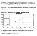
- illustration 1 shows a study of the exothermicity of the oxidation of Cu catalysts according to the production instructions mentioned in Example 1.1, but with different Compositions and application depending on the Cu content. Under 12 wt .-% CuO content in the precursor while the catalysts are in the non-pyrophoric range.
- the catalyst was introduced into a heatable reactor. The volume was adjusted so that in each case always the same amount of active material copper was in the reactor. The catalyst was reduced under hydrogen and at elevated temperature.
- a gas composition of 4 vol.% CO, 8 vol.% CO 2 , 28 vol.% N 2 , 30 vol.% H 2, and 30 vol.% H 2 O was passed over the catalyst at a GHSV of Given 7,500 h -1 .
- a temperature ramp between 130 and 300 ° C was run through and found the temperature at which the catalyst reaches the equilibrium of the reaction.
- Example 2.1 In the apparatus described in Example 2.1, several changes of atmosphere were carried out on the catalyst at about 200 ° C. The percentage refers to the change in CO concentration in the exhaust gas.
- the 20% given for the first catalyst therefore means that the CO concentration has been reduced by the atmospheric changes by 20% compared to the value before the change of atmosphere. This in turn indicates that the catalyst has become significantly more active.
- Example 2.1 In the apparatus described in Example 2.1, the water vapor condensation was carried out on the catalyst. Subsequently, the catalyst was brought back under reformate to 130 ° C and run through the temperature ramp described in Example 2.1. It was found the temperature at which the catalyst now reaches the equilibrium of the reaction.
- Example 2.1 The experiment was carried out analogously to Example 2.1, but with a GHSV of 5,000 h -1 and a gas composition of 8 vol.% CO, 10 vol.% CO 2 , 43 vol.% H 2 , 26 vol.% H 2 O has been set.
- the catalyst reached the thermodynamic equilibrium at 220 ° C.
- Example 2.1 Example 1.1 230 ° C Example 1.2 240 ° C Example 1.3 > 300 ° C Example 1.4 250 ° C Example 1.5 260 ° C Example 1.6 280 ° C Example 1.7 > 300 ° C Example 1.8 245 ° C Example 1.9 235 ° C Example 1.10 240 ° C Example 1.11 235 ° C Example 1.12 260 ° C Example 1.13 220 ° C Example 1.14 215 ° C catalyst Change due to change of atmosphere [%] Reaching the GGW after water vapor condensation [° C] Description Example 2.2 Description Example 2.3 Example 1.1 -20% over 16 h [1] 230 ° C [1] Example 1.2 +/- 0% over 16 h [1] 240 ° C [1] Example 1.3 +/- 0% over 28 h [2] > 300 ° C [2] 1 Mech. Hardness after removal still good (lateral compressive strength> 5 N). 2 Mech. Hardness after removal insufficient
- a Cr-free comparative catalyst showed a significantly worse performance than the catalysts of the invention.
- Figure 2 shows a typical trace of catalyst 1.1.
- Figure 3 shows change of atmosphere on catalyst 1.1.
Landscapes
- Chemical & Material Sciences (AREA)
- Chemical Kinetics & Catalysis (AREA)
- Engineering & Computer Science (AREA)
- Organic Chemistry (AREA)
- Materials Engineering (AREA)
- General Chemical & Material Sciences (AREA)
- Sustainable Energy (AREA)
- Electrochemistry (AREA)
- Life Sciences & Earth Sciences (AREA)
- Sustainable Development (AREA)
- Manufacturing & Machinery (AREA)
- Health & Medical Sciences (AREA)
- General Health & Medical Sciences (AREA)
- Combustion & Propulsion (AREA)
- Inorganic Chemistry (AREA)
- Catalysts (AREA)
- Hydrogen, Water And Hydrids (AREA)
- Carbon And Carbon Compounds (AREA)
Abstract
Description
- Die Erfindung betrifft eine katalytische Zusammensetzung und ein Verfahren zur Tieftemperaturkonvertierung von Kohlenmonoxid (CO) und Wasser (H2O) zu Kohlendioxid (CO2 und Wasserstoff (H2), insbesondere für die Verwendung in Brennstoffzellensystemen. Die Erfindung betrifft weiterhin ein Verfahren zu Herstellung eines solchen Katalysators, wobei der Katalysator ein chromfreier, nicht pyrophorer Kontakt für die Wassergasshiftreaktion ist, der auf einer Hydrotalcitphase als Precursor beruht.
- Das Verfahren zur Herstellung von Wasserstoff durch die Konvertierungsreaktion (auch: Shiftreaktion) von H2O und CO zu H2 und CO2 in einem fluiden Medium, im Besonderen zur Herstellung von Wasserstoff in einem Gasstrom, der vor allem aus Wasserstoff, Wasser und Kohlenmonoxid besteht, dient vor allem der Generierung von hochreinem Wasserstoff für Brennstoffzellenanwendungen, im Besonderen zur Verwendung für Brennstoffzellen, die auf Protonenaustauschmembranen (PEM, proton exchange membrane) basieren.
- Brennstoffzellen setzen direkt chemische Energie zu elektrischer Energie um und vermeiden damit mechanische Verfahren. Sie werden als Energiequelle für verschiedene Anwendungen vorgeschlagen. Eine Brennstoffzelle kann zwei- bis dreimal effektiver als bisherige Verbrennungskraftmaschinen wirken und zeigt dabei sehr geringe Emissionen an Giftstoffen, wie Kohlenmonoxid (CO), Stickoxiden (NOx) oder Kohlenwasserstoffen.
- Brennstoffzellen, eingeschlossen PEM-Brennstoffzellen (auch als SPE-, solid polymer electrolyte, Brennstoffzellen bekannt) generieren die elektrische Energie durch Reaktion zwischen Wasserstoff als Reduktionsmittel und Sauerstoff als Oxidationsmittel, die beide der Zelle zugegeben werden. Bei einer PEM-Brennstoffzelle sind Anode und Kathode voneinander durch eine Membran getrennt, die im Normalfall aus einem lonentauscherharz aufgebaut ist. Als Material für Anode und Kathode kommt üblicherweise eine feine Mischung aus lonentauscherharz und Kohlenstoffpartikeln, intensiv vermischt mit Katalysatorkörnern, zum Einsatz. Im typischen Betrieb einer solchen Zelle wird Wasserstoffgas elektrolytisch an einer aus Platin auf leitendem Kohlenstoffruß bestehenden Anode zu Protonen oxidiert. Die Protonen passieren die Membran, die ein Fluorsulfonsäurepolymer sein kann. Wasser (H2O) wird produziert, wenn die Protonen mit dem Sauerstoff in Kontakt kommen, der elektrolytisch an der Kathode reduziert wurde. Die Elektronen fließen durch einen externen Stromkreislauf dieses Prozesses und verrichten die Arbeitsleistung. Beispiele für Membranen und Elektroden Aufbau finden sich in
US 5,272,017 . - Brennstoffzellen brauchen sowohl eine Sauerstoff- als auch eine Wasserstoffquelle, um zu funktionieren. Der Sauerstoff kann einfach in reiner Form (als O2) der Luft entnommen werden. Wasserstoff jedoch ist nicht in ausreichender Quantität in der Luft vorhanden, um Brennstoffzellenanwendungen damit zu betreiben. Die geringe Energiedichte (pro Volumen) von isoliertem Wasserstoffgas im Vergleich zu konventionellen Kohlenwasserstoffen macht die direkte Versorgung von Brennstoffzellen mit Wasserstoff für die meisten Anwendungen ungünstig, da ein sehr großes Volumen von Wasserstoffgas benötigt würde, um dieselbe Energie zu erhalten, die in einem sehr viel kleineren Volumen an konventionellen Kohlenwasserstoffen wie Erdgas, Alkohol oder Öl enthalten ist. Daher ist die Umsetzung von den genannten kohlenwasserstoffbasierten Brennstoffen zu Wasserstoffgas eine attraktive Quelle für Wasserstoff für Brennstoffzellenanwendungen.
- Die Entfernung von Verunreinigungen wie Schwefel aus den Startmaterialien und die Verringerung der Konzentration an Oxidationsprodukten, die während des Umsetzungsprozesses gebildet werden, so zum Beispiel Kohlenmonoxid, sind die Herausforderungen bei der Wasserstoffproduktion. Brennstoffzellen werden durch geringe Konzentrationen an CO rasch außer Kraft gesetzt, da das CO den Katalysator an der Anode vergiftet. Trotz der Entwicklung von immer stärker CO resistenten Pt/Ru-Anoden sind die Brennstoffzellen weiterhin darauf angewiesen, dass die Wasserstoffquelle Wasserstoff mit einer geringeren CO-Konzentration als 50 ppm liefert.
- Derzeit industriell genutzte Methoden zur Produktion von hochreinem H2 (damit ist Wasserstoff gemeint, der für Brennstoffzellen ausreichend niedrige Konzentrationen an Schwefelkomponenten und CO enthält) sind für die Brennstoffzellenanwendungen nicht anwendbar. Die Produktion von Wasserstoffgas aus natürlich vorkommenden Kohlenwasserstoffen ist in der chemischen Industrie weit verbreitet, zum Beispiel für die Darstellung von Ammoniak aus Stickstoff und Wasserstoff oder bei der Herstellung von Alkohol. Eine Vielzahl von Schritten, die unterschiedliche, hochentwickelte Katalysatoren benötigen, werden in der industriellen Produktion von Wasserstoff genutzt. Eine Serie von Reaktionen wird zum Beispiel typischerweise gebraucht, um die Konzentration an CO unter die benötigten Schwellenwerte, z. B. 50 ppm, zu drücken. Viele dieser Stufen brauchen hohe Drücke (z. B. über 70 bar), hohe Reaktionstemperaturen (zum Teil über 800 °C) und benutzen selbsterhitzende, pyrophore Katalysatoren. Die Dimension und das Gewicht der Anlagen, die benötigt werden, um solche Prozesse sicher ausführen zu können, ist viel zu groß für viele Brennstoffzellenanwendungen, so z. B. im Automobil oder in stationären Hausanlagen. Während die mit diesen Bedingungen verbundenen Risiken erfolgreich in der Umgebung einer industriellen Produktionsstätte gemeistert werden können, sind sie jedoch nicht akzeptabel für die meisten Brennstoffzellenanwendungen.
- Die Wassergasshiftreaktion (WGS) ist eine wohlbekannte katalytische Reaktion, die, neben weiteren Anwendungen, auch zur Produktion von Wasserstoff in einem Gasstrom durch chemische Reaktion von CO mit Wasserdampf eingesetzt wird und nach der folgenden Stöchiometrie abläuft:
CO + H2O → CO2 + H2
- Dabei benötigt die Reaktion für den Ablauf einen Katalysator. Typische Katalysatoren für diese Reaktion basieren auf Kombinationen von Eisenoxid mit Chromoxid (bei hohen Temperaturen um ca. 350 °C) oder Mischungen aus Kupfer- und Zinkmaterialien (bei niedrigen Temperaturen um ca. 250 °C). Wird die WGS bei Temperaturen unter 300 °C betrieben, so spricht man von einer Tieftemperaturkonvertierung (TTK).
- Die derzeitig kommerziell genutzten Wassergasshiftkatalyatoren (WGS-Katalysatoren) zeigen eine Reihe von Nachteilen für Brennstoffzellenanwendungen. Viele kommerzielle WGS-Katalysatoren sind selbsterhitzend und pyrophor, wenn sie Luftsauerstoff ausgesetzt werden. Kommerzielle Hochtemperatur-WGS-Katalysatoren auf Basis von Eisen-Chrom im reduzierten Zustand erreichen Temperaturen von etwa 400 °C, wenn sie atmosphärischen Bedingungen ausgesetzt werden. Ein ähnliches Bild zeigen kommerzielle Kupfer-Zink-basierte Tieftemperatur-WGS-Katalysatoren im reduzierten Zustand, die bei Kontakt mit Luftsauerstoff Temperaturen von bis zu 750 °C erreichen. Der Kontakt von Luft mit WGS-Katalysatoren, die Kupferoxid im reduzierten Zustand auf Ceroxid enthalten, führt zu einer Temperaturerhöhung um etwa 500 bis 600 °C, Platin-Ceroxid-WGS-Katalysatoren erfahren ähnliche Temperaturerhöhungen um etwa 400 °C. In vielen Fällen führt ein solcher rascher und heftiger Temperaturanstieg zum Sintern des Katalysators, was zu einer dauerhaften Zerstörung des Kontaktes führen kann. Ein solcher Temperaturanstieg kann auch dazu führen, dass der reduzierte Kontakt sich spontan an Luft entzündet.
- Während die genannten Materialien für den Gebrauch in der industriellen Synthese gut zu verwenden sind, da hier die Reaktionsbedingungen genau überwacht werden können und geeignete Sicherheitsmaßnahmen getroffen werden, um den Kontakt zu Luft zu verhindern, stellen solche Katalysatoren ein erhebliches Risiko dar, wenn sie in Brennstoffzellenanwendungen, wie Automobilen oder stationären Hausanwendungen, eingebaut werden sollten.
- Da viele in den Katalysatoren benutzte Materialien auch noch sehr teuer sind, wird ebenfalls nach Katalysatoren gesucht, die bei gleicher oder verbesserter Aktivität billiger sind.
- WGS-Katalysatoren sind intensiv beforscht worden. Einen Review bieten Jaques Barbier und Daniel Duprez, Applied Catalysis B: Environmental 4 (1994) 105 bis 140 "Steam effects in three way catalysts", wobei auf eine Reihe von katalytischen Systemen eingegangen wird, einschließlich Systemen, die auf Aluminiumoxid geträgert sind, Ceroxid-Promotoren und einer Reihe von Edelmetallsystemen mit Platin (Pt), Rhodium (Rh) und Palladium (Pd).
-
WO 02/26619 A2 - Pyrophore Katalysatoren haben einen deutlichen Nachteil. Lange und genau zu befolgende Protokolle sind notwendig, um Aktivierung und Passivierung durchzuführen, damit sich der Kontakt an Luft stabil verhält. Außerdem wird spezielle Ausrüstung für diese Protokolle benötigt, so zum Beispiel Durchflussmesser. Aufgrund der exothermen Natur der Reduktion eines Kupferkontaktes erfordert die Aktivierung eines üblicherweise pyrophoren Kupfer-Tieftemperaturkonvertierungs (TTK)-Katalysators eine intensive Überwachung sowohl der Temperatur als auch der Dosierung des reduzierenden Gases (üblicherweise Wasserstoff), die über ein Trägergas (normalerweise Stickstoff oder Erdgas) erfolgt. In einer typischen Aktivierungsprozedur wird eine geringe Menge an Wasserstoff in einem Trägergas bei geringen Temperaturen auf den Katalysator gegeben. Dann wird die Temperatur des Katalysatorbettes langsam auf eine mittlere Temperatur erhöht. Ist diese erreicht, wird die Konzentration an Wasserstoff im Trägergas allmählich gesteigert. Diese iterativen Schritte werden fortgesetzt, bis das Katalysatorbett komplett reduziert ist. Geeignete Vorsichtsmaßnahmen müssen getroffen werden, um die Temperatur unterhalb von 230 °C zu halten, da der Kupferkontakt oberhalb dieser Temperaturschwelle zu sintern beginnt. Analog müssen geeignete Kontrollen und Prozeduren genutzt werden, um sicher einen gebrauchten pyrophoren Katalysator aus dem Reaktor zu entfernen, da die Oxidation des kupferhaltigen Materials wieder in einer exothermen Reaktion stattfindet. Der Katalysator bedarf eines Passivierungsschrittes, um sicher den Reaktor entladen zu können. In einer typischen Passivierungsprozedur wird in ein inertes Trägergas (üblicherweise Stickstoff) langsam Luft eindosiert, um die Konzentration an Sauerstoff allmählich anzuheben. Die langsame, stufenweise Konzentrationssteigerung von Luft benötigt spezielle Durchflussmesser und Überwachungsausstattung (Catalyst Handbook Second Edition; Twigg, M.V., Ed.; Wolfe Publishing, 1989). Die Protokolle und die verbundene Ausrüstung für die Aktivierung und die Passivierung des Materials tragen zu den Nutzungsproblemen und den Kosten der pyrophoren TTK-Katalysatoren bei.
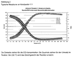
- In Journal of Power Sources 118 (2003) 61 bis 65 beschreibt die Engelhard Corperation, vertreten durch W. Ruettinger, O. Ilinich und R. J. Farrauto, einen Selektra Shift Katalysator, der eine nicht-pyrophore Alternative zu den gängigen Cu-ZnO-Katalysatoren darstellen soll. Dieser Katalysator erreicht bei der niedrigen GHSV von 2.500 h-1 und einer Gaszusammensetzung von 8 % CO, 10 % CO2, 43 % H2, 26 % H2O das Gleichgewicht der Shiftreaktion bei 220 °C. Wie die Abbildung 4 der Veröffentlichung zeigt, deaktiviert der Katalysator bei Kontakt mit Luft leicht. Die Grafik 5, die die Stabilität des Katalysators gegenüber Kondenswasser zeigen soll, zeigt ebenso eine Deaktivierung. Ein entsprechendes Verfahren ist in
WO 02/26619 - S. Velu et al. beschreiben in "Oxidative steam reforming of methanol over CuZnAl(Zr)-oxide catalysts, a new and efficient method for the production of CO-free hydrogen for fuel cells", Chem. Commun.(1999), 2341-2342, einen Cu/Zn/Al/(Zr)-haltigen Katalysator, der unter Zusatz von Sauerstoff eine hohe Stabilität und katalytische Aktivität in der Methanolreformierung zeigt.
- Gesucht wurde ein WGS-Katalysator mit einer signifikant geringeren Wärmetönung bei Kontakt mit Luftsauerstoff, mit geringeren Produktionskosten, mit wenigstens vergleichbarer katalytischer Aktivität im Vergleich zu existierenden Systemen, mit einer stabilen Performance bei Kontakt mit Luftsauerstoff bzw. bei Kondensation von Wasser auf dem Katalysator und in einer Form, die stabil, haltbar und praktisch für den Gebrauch in Brennstoffzellenanwendungen ist. Insbesondere muss der Katalysator typische Anfahr- und Abschaltprozesse (Kondensation von Wasser auf dem Katalysator bzw. Abschaltung durch Überströmen mit Luft, d. h. Atomosphärenwechsel) gut überstehen.
- Die Aufgabe der Erfindung bestand damit in der Bereitstellung eines solchen WGS-Katalysators.
- Gegenstand der Erfindung ist damit ein chromfreier Katalysator wie in den Ansprüchen 1 bis 6 beschrieben.
- Gegenstände der Erfindung sind weiterhin ein Verfahren zur Herstellung eines solchen Katalysators sowie ein Verfahren zur Tieftemperaturkonvertierung von Kohlenmonoxid und Wasser zu Kohlendioxid und Wasserstoff, wie in den Ansprüchen 7 und 8, sowie in den Ansprüchen 9 und 10 beschrieben.
- Gegenstand der Erfindung ist die Verwendung wie in Anspruch 11 beschrieben
- Obwohl üblicherweise in der Gleichgewichtsreaktion CO + H2O → CO2 + H2 im Bereich niedriger Temperaturen von etwa 200 bis 300 °C kupferhaltige Kontakte in ihrem aktivierten Zustand aufgrund des hohen Anteils an reduziertem metallischen Kupfer pyrophor sind, wurde überraschend gefunden, dass durch Verringerung des Kupferanteils Katalysatoren präpariert werden können, die auch im reduzierten Zustand nicht als pyrophor gekennzeichnet werden müssen und trotzdem die notwendige Aktivität vorweisen. Weiterhin wurde überraschend gefunden, dass der erfindungsgemäße Kontakt unter den Bedingungen typischer Anfahr- und Abschaltprozesse, insbesondere bei Atmosphärenwechsel und Wasserdampfkondensation, keinen Aktivitätsverlust erleidet.
- Der erfindungsgemäße Katalysator enthält ein Mischoxid aus wenigstens CuO, ZnO und Al2O3, besonders bevorzugt aus wenigstens CuO, ZnO, Al2O3 und ZrO2.
- Strukturelle Basis dieser Katalysatoren ist der Hydrotalcit. Ein Hydrotalcit ist ein synthetischer anionischer Ton mit Bruzit-analogen Schichten der ungefähren Zusammensetzung:
MII 6MIII 2(OH)16CO3·4H2O,
wobei - M" mindestens ein zweiwertiges Metallion und
- MIII mindestens ein dreiwertiges Metallion darstellt.
- Erfindungsgemäß ist M" Kupfer und Zink, enthalten sein können zusätzlich aber auch andere zweiwertige Metallkationen, beispielsweise Fe, Co, Mg, Ca, Mn, Ni, Sr, Ba, vorzugsweise Mg, Ca, Sr, Ba oder Ni.
- Erfindungsgemäß ist MIII Aluminium, enthalten sein können zusätzlich aber auch andere dreiwertige Metallkationen, beispielsweise ausgewählte aus der Reihe der Lanthaniden, La, Sc, Y, Ga, In oder auch Fe, vorzugsweise Elemente, ausgewählt aus der Reihe der Lanthaniden, La, Sc oder Y.
- Im erfindungsgemäßen Katalysator liegen die genannten Elemente nach der Kalzination des Katalysatorprecursors als Oxide in folgenden Verhältnissen vor:
- CuO von 6 bis 12 Gew.-%.
- ZnO von 40 bis 80,5 Gew.-%, bevorzugt von 50 bis 77 Gew.-%, besonders bevorzugt von 60 bis 75 Gew.-%.
- Al2O3 von 17,5 bis 45 Gew.-%, bevorzugt von 17,5 bis 35 Gew.-%, besonders bevorzugt von 17,5 bis 25 Gew.-%.
- Um den Strukturtypus des Hydrotalcits zu erhalten, muss wenigstens ein Al2O3-Anteil von 17,5 Gew.-% im Kontakt vorhanden sein.
- Näheres dazu ist in F. Trifirö et al., Preparation and Properties of Copper Synthetic Clays, in: Characterization of Porous Solids, Hrsg.: K.K. Unger et al. (1988), Seite 571 ff. beschrieben.
- Das Mischoxid enthält vorteilhafterweise zusätzlich Zirkoniumoxid in einer Menge von 0 bis 10 Gew.-%, bevorzugt von 1 bis 7 Gew.-%, besonders bevorzugt von 2 bis 5 Gew.-%.
- Das ZrO2 sorgt dafür, dass die Schichtstruktur "aufgebrochen" wird, damit die einzenen Aktivzentren katalytisch besser zugänglich sind. Um diese vorteilhafte Wirkung zu erzielen, werden in besonderen Ausführungsvarianten beispielsweise ca. 2,5 Gew.-% ZrO2 eingesetzt.
- Dieselbe Aufgabe erfüllen auch mögliche Zusätze von TiO2, SiO2 und/oder MnO2, die ebenfalls eine hohe Affinität auf CO aufweisen.
- Neben den erfindungsgemäßen und vorteilhaften Oxiden kann das Mischoxid weitere Oxide, wie beispielsweise Erdalkalimetalloxide, aufweisen. Sind im Mischoxid solche weiteren Oxide enthalten, dann höchstens in einer Menge von 25 Gew.-%, vorzugsweise höchstens 10 Gew. %.
- Der erfindungsgemäße Katalysator kann neben dem oben beschriebenen Mischoxid in geringen Mengen natürlich weitere Verbindungen enthalten, wie sie beispielweise als übliche Verunreinigungen auftreten.
- Der erfindungsgemäße Katalysator ist chromfrei.
- Er enthält vorteilhafterweise kein Edelmetall. Edelmetalle zeigen im genannten Temperaturbereich nur bei sehr hohen und somit unwirtschaftlichen Konzentrationen eine ausreichende Aktivität auf die Shiftreaktion.
- Der Precursor des erfindungsgemäßen Katalysators liegt erfindungsgemäß im Wesentlichen als Hydrotalcit vor. Daneben können aber auch andere Strukturen, wie beispielsweise Aluminiumoxide o. ä., auftreten. "Im Wesentlichen" bedeutet im Rahmen dieser Erfindung zu mindestens 80 Gew.-%, vorteilhafterweise zu mindestens 90 Gew.-%, besonders bevorzugt zu mindestens 95 Gew.-%.
- Die Hydrotalcit-Struktur wird nachgewiesen durch XRD.
- Die Herstellung des erfindungsgemäßen Katalysators für die Tieftemperaturkonvertierung von Kohlenmonoxid und Wasser zu Wasserstoff und Kohlendioxid kann durch Fällung von Precursorsubstanzen erfolgen.
- Als Edukte werden Kupfer, Zink und Aluminium sowie gegebenenfalls weitere Elemente, wie weiter oben bereits beschrieben, eingesetzt.
- Der Aluminiumanteil kann dabei in verschiedenen Strukturvarianten, beispielsweise auch als Böhmit oder Aluminasol, vorgelegt werden. Als Edukte für die anderen Metalle bieten sich deren Salze in Form von Nitraten, Chloriden, Carbonaten, Acetaten oder Sulfaten an. Besonders bevorzugt werden die Nitrate, Carbonate und Acetate der Metallkationen genutzt.
- Erfindungsgemäß ist die Fällphase im Wesentlichen ein Hydrotalcit. Um diese Struktur zu erhalten, ist besonders auf die Einhaltung von pH-Wert und Temperatur zu achten.
- Die Fällung erfolgt vorteilhafterweise im basischen Milieu. Vorzugsweise wird dafür eine Mischlösung aus Soda und NaOH eingesetzt, besonders bevorzugt eine Mischlösung aus 2 molarer NaOH und 0,3 molarer Sodalösung. Die Fällung kann jedoch auch durch andere basische Lösungen erfolgen. Bevorzugt verläuft sie bei einem pH-Wert größer 7,2, besonders bevorzugt bei einem pH-Wert größer 7,5.
- Die Fällung erfolgt vorteilhafterweise bei einer Temperatur zwischen 10 und 80 °C, bevorzugt zwischen 15 und 50 °C, besonders bevorzugt zwischen 20 und 40 °C.
- Nach der Fällung wird der Katalysator in üblicher Weise gewaschen, getrocknet, eventuell noch calciniert und mit Grafit oder einem anderen Schmiermittel tablettiert. An die Tablettierung kann sich eine weitere Calcination anschließen.
- Der erfindungsgemäß hergestellte Katalysator ist nicht pyrophor. Die Pyrophorizität eines Materials wird nach der EG-Richtlinie 92/69/EWG, Anhang A.13, festgestellt. Ein weiterer möglicher Test ist der "Test auf Selbstentzündung" mit der Prüfung nach Grewer (VDI 2263, Blatt 1, Kap. 1.4.1), bei der die Temperaturerhöhung einer Probe von 10 ml Volumen bei Inkontaktbringung der Probe mit Luftsauerstoff beobachtet wird. Eine weitere Testmöglichkeit ist mit der "Drahtkorbmethode" gegeben, die zur Einstufung des Selbstentzündungsverhaltens für Transportzwecke dient (GGVS/ADR Anlage A, UN-Recommendations on the Transport of Dangerous Goods, Model Regulations, Abschnittte 2.4.3.2f and Manual of Tests and Criteria, Abschnitt 33.3).
- Der erfindungsgemäße Katalysator weist nach den drei oben genannten Tests keine Pyrophorizität auf.
- Zur Quantifizierung wurde folgendes Untersuchungsverfahren zum thermischen Verhalten von Katalysatoren herangezogen:
- Die Katalysatoren werden gemahlen und in einer Wasserstoff/Argon-Atmosphäre bei 350 °C reduziert. Sie werden dann bei 250 °C für zwei Stunden einem Gasstrom mit 10 % O2 ausgesetzt. Das DTA-Signal bei der Reoxidation ist proportional zu der Exothermie der Reaktion und damit der Pyrophorizität.
-
Abbildung 1 zeigt die Abhängigkeit der Exothermie von dem Cu-Gehalt von Cu-Katalysatoren, die sich aus dem Hydrotalcit-Precursor ergeben. Damit wird bei seinem Einsatz das durch Pyrophorizität gegebene Risiko durch den Kontakt von Luft mit reduzierten Katalysatoren deutlich verringert. Die Reduzierung des Risikos macht den Katalysator wesentlich einfacher im Umgang, sowohl was seine Aktivierung wie auch seine Passivierung betrifft. - Die katalytische Aktivität des erfindungsgemäßen Katalysators ist vergleichbar mit der existierender Systeme. Vorteilhaft ist jedoch, dass der Katalysator bei Atmosphärenwechsel und Wasserdampfkondensation keinen Aktivitätsverlust erleidet. Da beide Schritte typische Bedingungen beim Abschalten bzw. beim Einschalten eines Brennstoffzellensystems sind, ist es wichtig, dass Atmosphärenwechsel oder Wasserdampfkondensation zu keinem schädlichen Aktivitätsverlust führen.
- Der erfindungsgemäße Katalysator ist stabil, haltbar und ökonomisch herstellbar. Die Gefahr der Sinterung der Aktivmasse bei Kontakt mit Luft ist sehr gering. Er zeigt auch nach Nutzung und Kondensation unter Wasserdampf ausreichende Härte und Seitendruckfestigkeit.
- Der erfindungsgemäße Katalysator kann in einer beliebigen Form eingesetzt werden, beispielsweise als Beschichtung eines Monolithen, als Formkörper in Strang- oder Tablettenform oder als Pulver. Eine stabile Form wird bevorzugt, um Abrieb und Staubbildung zu vermeiden.
- Die vorliegende Erfindung erfüllt alle Anforderungen, die an einen verbesserten WGS-Katalysator gestellt werden. Der erfindungsgemäße Katalysator ist damit geeignet, um Wasserstoff aus einem Gasstrom zu erzeugen und praktikabel für den Gebrauch in Brennstoffzellenanwendungen.
- Das erfindungsgemäße Verfahren zur Tieftemperaturkonvertierung von Kohlenmonoxid und Wasser zu Kohlendioxid und Wasserstoff unterscheidet sich von üblichen Verfahren des Standes der Technik durch den Einsatz eines chromfreien Katalysators, der ein Mischoxid aus wenigstens Kupferoxid, Zinkoxid und Aluminiumoxid enthält, wobei der Katalysatorprecursor im Wesentlichen als Hydrotalcit vorliegt und der Gehalt an Kupferoxid höchstens 20 Gew.-% beträgt.
- Ansonsten kann die WGS-Reaktion unter den üblichen Bedingungen durchgeführt werden. Vorteilhafterweise erfolgt sie bei Temperaturen von 150 bis 350 °C, besonders bevorzugt bei Temperaturen von 180 bis 320 °C. Der Katalysator ist aber auch in WGS-Reaktionen, die bei Temperaturen ablaufen, für die herkömmliche TTK-Katalysatoren des Standes der Technik einsetzbar sind, geeignet.
- In einer vorteilhaften Anwendung wird das erfindungsgemäße Verfahren zur Erzeugung von Wasserstoffgas aus einem Gasstrom oder einer Gasprobe aus CO und Wasser durchgeführt. In anderen Anwendungen kann der erfindungsgemäße Katalysator in einem Zwischenschritt eines chemischen Prozesses zur Generierung von Wasserstoff aus einem Gasstrom durch WGS-Reaktion genutzt werden.
- Die Erfindung führt zu einen WGS-Katalysator und Verfahren zu seiner Nutzung, wobei das durch Pyrophorizität gegebene Risiko durch den Kontakt von Luft mit reduzierten Katalysatoren deutlich vermindert ist.
- Die Erfindung sei durch die nachstehenden Beispiele in nicht einschränkender Weise erläutert:
- Die nachfolgend aufgeführten Begriffe werden im Rahmen dieser Erfindung wie folgt definiert bzw. erläutert:
- "Atmosphärenwechsel": Bei Betriebtemperatur wird das Betriebsgas (CO, CO2, H2O, H2, N2) abgeschaltet und der Katalysator mit Luft überspült. Nach wenigen Minuten wird wieder das Betriebsgas auf den Katalysator gestellt.
- "Wasserdampfkondensation": Im laufenden Betrieb werden Reaktoreingang und - ausgang verschlossen. Der Reaktor kühlt über Nacht ab. Das im Betriebsgas enthaltene Wasser kondensiert auf dem Katalysator aus. Nach 12 bis 16 Stunden wird der Reaktor wie gewohnt wieder mit Betriebsgas angefahren.
- "DTA": Die "Differential thermal analysis" ist eine Analysenmethode zur Bestimmung der emitierten oder absorbierten Wärme (exo- bzw. endotherm) einer Probe als Funktion der Temperatur und/oder der Zeit.
- "GHSV": Die "Gas hourly space velocity" ist eine Angabe über den Gasfluss eines Reaktionsgases in Litern pro Liter Katalysator und pro Stunde bei Standardtemperatur und Standarddruck.
- "Seitendruckfestigkeit", "SDF": Die Seitendruckfestigkeit ist ein Maß für die Stabilität eines Materials bei Ausübung von Druck auf seine Seitenflächen. Das Material wird dazu zwischen zwei Stempeln eingespannt (Vorkraft 0,5 N), die sich dann mit 1,6 mm/min Prüfgeschwindigkeit aufeinander zu bewegen und das Material zerdrücken. Die Kraft, die zum Zerdrücken des Materials benötigt wird, wird aufgezeichnet. Daten ergeben sich über eine statistische Auswertung von wenigstens 20 Formkörpern.
- 1,031 kg Cu-Nitratlösung (19,4 %ig), 9,983 kg Zn-Nitratlösung (18,03 %ig) und 5,388 kg Al-Nitratlösung (8,12 %ig) wurden vermischt (Lösung 1). 0,1462 kg Zr-Carbonat wurden in 0,179 kg HN03 (69,3 %ig) gelöst (Lösung 2). Lösung 3 wurde angesetzt aus 2 molarer NaOH und 0,3 molarer Sodalösung. Lösung 3 wurde vorgelegt, die Lösungen 1 und 2 parallel dazu gegeben.
- Das Gemisch wurde auf 50 °C hochgeheizt und 1 Stunde nachgerührt. Der pH-Wert lag am Ende bei 8,0.
- Die Probe wurde anschließend filtriert, gewaschen, getrocknet, bei 550 °C für vier Stunden getempert und zum Schluss mit Grafit tablettiert.
- Wie in
WO 02/26619 A2 - Beispiel 1.3: - Vergleichsbeispiel (typischer hoch-kupferhaltiger Katalysator) Synthese eines Katalysators der Zusammensetzung: 49 Gew.-% CuO, 30 Gew.-% ZnO, 18,5 Gew.-% Al2O3, 2,5 Gew.-% ZrO2
- Nitratlösungen aus Cu, Zn und Al wurden im Verhältnis der Oxide (Gew.-%) 49 : 30 : 18,5 vermischt. Dazu wurde Zirkoniumcarbonat im Verhältnis der Oxide 2,5 Gew.-% in konzentrierter Salpetersäure gelöst. Eine Mischlösung aus Natronlauge und Soda wurden angesetzt. Die Lösungen wurden vereinigt, gerührt und der Katalysatorprecursor gefällt. Die Probe wurde anschließend analog Beispiel 1.1 filtriert, gewaschen, getrocknet, bei 550 °C für vier Stunden getempert und zum Schluss tablettiert.
- Sasol-Al2O3-Kugeln wurden in der Porzellanschale vorgelegt und unter Rühren wurde Cernitratlösung zugetropft. Die Kugeln wurden nach dem Tränken kurz nachgerührt und sofort getrocknet und kalziniert. In einem zweiten Arbeitsschritt analog dem ersten wurden die Kugeln mit Cu-Nitratlösung beschichtet. Die Trocknung erfolgte über jeweils 2 h bei 120 °C, die Kalzination bei 550 °C im Muffelofen.
- Es wurde analog Beispiel 1.1 verfahren, wobei zusätzlich eine Cr-Nitratlösung (in Lösung 1) zugegeben wurde.
- Es wurde analog Beispiel 1.1 verfahren, wobei Lösung 1 ausschließlich aus der Zn-Nitratlösung bestand.
- Es wurde analog Beispiel 1.1 verfahren, wobei an Stelle von Al-Nitratlösung eine Ce-Nitratlösung eingesetzt wurde.
- Es wurde analog Beispiel 1.1 verfahren, wobei ein Teil des Aluminiumoxid (13 Gew.-%) als Versal beigemischt wurde.
- Es wurde analog Beispiel 1.1 verfahren, wobei zusätzlich eine Fe-Nitratlösung (in Lösung 1) zugegeben wurde.
- Es wurde analog Beispiel 1.1 verfahren.
- Es wurde analog Beispiel 1.1 verfahren.
- Es wurde analog Beispiel 1.1 verfahren.
- Es wurde analog Beispiel 1.1 verfahren.
- Es wurde analog Beispiel 1.1 verfahren.
-
Abbildung 1 zeigt eine Untersuchung der Exothermie der Oxidation von Cu-Katalysatoren nach der unter Beispiel 1.1 genannten Herstellvorschrift, jedoch mit unterschiedlichen Zusammensetzungen und Auftragung in Abhängigkeit des Cu-Gehalts. Unter 12 Gew.-% CuO-Gehalt im Precursor liegen dabei die Katalysatoren im nicht-pyrophoren Bereich. - In einen beheizbaren Reaktor wurde der Katalysator eingefüllt. Das Volumen wurde so angepasst, dass sich jeweils immer gleich viel Aktivmasse Kupfer im Reaktor befand. Der Katalysator wurde unter Wasserstoff und bei erhöhter Temperatur reduziert.
- Eine Gaszusammensetzung von 4 Vol.-% CO, 8 Vol.-% CO2, 28 Vol.-% N2, 30 Vol.-% H2 und 30 Vol.-% H2O wurde über den Katalysator mit einer GHSV von 7.500 h-1 gegeben. Dabei wurde eine Temperaturrampe zwischen 130 und 300 °C durchlaufen und die Temperatur festgestellt, bei der der Katalysator das Gleichgewicht der Reaktion erreicht.
- Die Ergebnisse sind in der Tabelle 1 festgehalten.
- In der in Beispiel 2.1 beschriebenen Apparatur wurden bei etwa 200 °C mehrere Atmosphärenwechsel an dem Katalysator durchgeführt. Die Prozentangabe bezieht sich auf die Veränderung der CO-Konzentration im Abgas. Die für den ersten Katalysator angegeben - 20 % bedeuten demnach, dass sich die CO-Konzentration durch die Atmosphärenwechsel um 20 % gegenüber dem Wert vor dem Atmosphärenwechsel verringert hat. Das wiederum zeigt an, dass der Katalysator signifikant aktiver geworden ist.
- Die Ergebnisse sind in der Tabelle 2 festgehalten.
- In der in Beispiel 2.1 beschriebenen Apparatur wurde die Wasserdampfkondensation auf dem Katalysator durchgeführt. Anschließend wurde der Katalysator wieder unter Reformat auf 130 °C gebracht und die in Beispiel 2.1 beschriebene Temperaturrampe durchlaufen. Es wurde die Temperatur festgestellt, bei der der Katalysator nun das Gleichgewicht der Reaktion erreicht.
- Die Ergebnisse sind in der Tabelle 2 festgehalten.
- Der Versuch wurde analog Beispiel 2.1 durchgeführt, wobei jedoch eine GHSV von 5.000 h-1 und eine Gaszusammensetzung von 8 Vol.-% CO, 10 Vol.-% CO2, 43 Vol.-% H2, 26 Vol.-% H2O eingestellt wurde. Der Katalysator erreichte das thermodynamische Gleichgewicht bei 220°C.
Tabelle 1: Katalysator Erreichen des GGW [°C] Beschreibung Beispiel 2.1 Beispiel 1.1 230 °C Beispiel 1.2 240 °C Beispiel 1.3 > 300 °C Beispiel 1.4 250 °C Beispiel 1.5 260 °C Beispiel 1.6 280 °C Beispiel 1.7 > 300 °C Beispiel 1.8 245 °C Beispiel 1.9 235 °C Beispiel 1.10 240 °C Beispiel 1.11 235 °C Beispiel 1.12 260 °C Beispiel 1.13 220 °C Beispiel 1.14 215 °C Tabelle 2: Katalysator Veränderung durch Atmosphärenwechsel [%] Erreichen des GGW nach Wasserdampfkondensation [°C] Beschreibung Beispiel 2.2 Beschreibung Beispiel 2.3 Beispiel 1.1 -20 % über 16 h[1] 230 °C[1] Beispiel 1.2 +/- 0 % über 16 h[1] 240 °C[1] Beispiel 1.3 +/- 0 % über 28 h[2] > 300 °C[2] 1 Mech. Härte nach Ausbau noch gut (Seitendruckfestigkeit > 5 N).
2 Mech. Härte nach Ausbau ungenügend (nicht mehr messbar). - Der erfindungsgemäße Katalysator (Hydrotalcitstruktur; 10 Gew.-% CuO) zeigte in Versuchen bei einer anspruchsvoll niedrigen Temperatur von 220 °C (typische Reaktionstemperatur = 250 °C) und bei GHSV = 5000 NIGas/IKat·h einen CO-Umsatz von ca. 99 % des thermodynamischen Gleichgewichts und ist damit vergleichbar bzw. leicht verbessert gegenüber Cr-haltigen Katalysatoren des Standes der Technik (Nachstellung Katalysatoren gemäß
WO 02/26619 -
Abbildung 2 zeigt eine typische Messkurve an Katalysator 1.1. -
Abbildung 3 zeigt Atmosphärenwechsel an Katalysator 1.1.
Claims (11)
- Chromfreier Katalysator für die Tieftemperaturkonvertierung von Kohlenmonoxid und Wasser zu Wasserstoff und Kohlendioxid, enthaltend ein Mischoxid aus wenigstens Kupferoxid, Zinkoxid und Aluminiumoxid, wobei der Katalysatorprecur sor im Wesentlichen als Hydrotalcit vorliegt, der Gehalt an Kupferoxid von 6 bis 12 Gew.% beträgt und der Katalysator nicht pyrophor ist.
- Katalysator gemäß Anspruch 1, dadurch gekennzeichnet, dass das Mischoxid zusätzlich wenigstens Zirkoniumoxid enthält.
- Katalysator gemäß Anspruch 1 oder 2, dadurch gekennzeichnet, dass er kein Edelmetall enthält.
- Katalysator gemäß einem der Ansprüche 1 bis 3, dadurch gekennzeichnet, dass das Mischoxid 40 bis 80,5 Gew.-% Zinkoxid enthält.
- Katalysator gemäß einem der Ansprüche 1 bis 4, dadurch gekennzeichnet, dass das Mischoxid bis zu 45 Gew.-% Aluminiumoxid enthält.
- Katalysator gemäß einem der Ansprüche 1 bis 5, dadurch gekennzeichnet, dass das Mischoxid bis zu 10 Gew.-% Zirkoniumoxid enthält.
- Verfahren zur Herstellung eines chromfreien Katalysators für die Tieftemperatur-konvertierung von Kohlenmonoxid und Wasser zu Wasserstoff und Kohlendioxid, gemäß einem der Ansprüche 1 bis 6, dadurch gekennzeichnet, dass der Katalysator aus durch Fällung erhaltenen Precursorsubstanzen, enthaltend wenigstens Verwindungen von Kupfer, Zink und Aluminium, gewonnen wird und die Fällung im basischen Milieu stattfindet.
- Verfahren gemäß Anspruch 7, dadurch gekennzeichnet, dass zur Fällung eine Mischung aus Soda und Natriumhydroxid eingesetzt wird.
- Verfahren zur Tieftemperaturkonvertierung von Kohlenmonoxid und Wasser zu Kohlendioxid und Wasserstoff, dadurch gekennzeichnet, dass ein chromfreier Katalysator eingesetzt wird, der ein Mischoxid aus wenigstens Kupferoxid, Zinkoxid und Aluminiumoxid enthält, wobei der Gehalt an Kupferoxid 6 bis 12 Gew.-% beträgt, der Katalysatorprecursor im Wesentlichen als Hydrotalcit vorliegt und der Katalysator nicht pyrophor ist.
- Verfahren gemäß Anspruch 9, dadurch gekennzeichnet, dass die Tieftemperaturkonvertierung bei 150 bis 350 °C durchgeführt wird.
- Verwendung eines chromfreien Katalysators, definiert gemäß Anspruch 1, zur Erzeugung von Wasserstoff aus einem Gasstrom für Brennstoffzellenanwendungen.
Priority Applications (1)
| Application Number | Priority Date | Filing Date | Title |
|---|---|---|---|
| EP07787708A EP2049249B1 (de) | 2006-07-26 | 2007-07-19 | Katalysator für die tieftemperaturkonvertierung und verfahren zur tieftemperaturkonvertierung von kohlenmonoxid und wasser zu kohlendioxid und wasserstoff |
Applications Claiming Priority (3)
| Application Number | Priority Date | Filing Date | Title |
|---|---|---|---|
| EP06117843 | 2006-07-26 | ||
| EP07787708A EP2049249B1 (de) | 2006-07-26 | 2007-07-19 | Katalysator für die tieftemperaturkonvertierung und verfahren zur tieftemperaturkonvertierung von kohlenmonoxid und wasser zu kohlendioxid und wasserstoff |
| PCT/EP2007/057450 WO2008012255A2 (de) | 2006-07-26 | 2007-07-19 | Katalysator für die tieftemperaturkonvertierung und verfahren zur tieftemperaturkonvertierung von kohlenmonoxid und wasser zu kohlendioxid und wasserstoff |
Publications (2)
| Publication Number | Publication Date |
|---|---|
| EP2049249A2 EP2049249A2 (de) | 2009-04-22 |
| EP2049249B1 true EP2049249B1 (de) | 2012-05-23 |
Family
ID=38634636
Family Applications (1)
| Application Number | Title | Priority Date | Filing Date |
|---|---|---|---|
| EP07787708A Not-in-force EP2049249B1 (de) | 2006-07-26 | 2007-07-19 | Katalysator für die tieftemperaturkonvertierung und verfahren zur tieftemperaturkonvertierung von kohlenmonoxid und wasser zu kohlendioxid und wasserstoff |
Country Status (7)
| Country | Link |
|---|---|
| US (1) | US9343767B2 (de) |
| EP (1) | EP2049249B1 (de) |
| JP (1) | JP5281572B2 (de) |
| CN (1) | CN101495226B (de) |
| CA (1) | CA2658453C (de) |
| DK (1) | DK2049249T3 (de) |
| WO (1) | WO2008012255A2 (de) |
Families Citing this family (12)
| Publication number | Priority date | Publication date | Assignee | Title |
|---|---|---|---|---|
| JP5477561B2 (ja) * | 2009-09-09 | 2014-04-23 | 戸田工業株式会社 | 炭化水素を分解する多孔質触媒体及びその製造方法、炭化水素から水素を含む混合改質ガスを製造する方法、並びに燃料電池システム |
| US8518853B2 (en) * | 2010-04-21 | 2013-08-27 | Sk Innovation Co., Ltd. | Nanometer-sized copper-based catalyst, production method thereof, and alcohol production method using the same through direct hydrogenation of carboxylic acid |
| GB201015605D0 (en) | 2010-09-17 | 2010-10-27 | Magnesium Elektron Ltd | Inorganic oxides for co2 capture from exhaust systems |
| JP5871312B2 (ja) * | 2011-01-17 | 2016-03-01 | 国立研究開発法人産業技術総合研究所 | 微粒子凝集体の製造方法、水蒸気改質触媒、水蒸気改質触媒の製造方法及び、水素製造方法 |
| CN103466546B (zh) * | 2013-09-06 | 2015-04-15 | 清华大学 | 一种将双功能吸附剂应用于吸附增强式水蒸气重整和水气变换反应的中温变压吸附方法 |
| GB201519139D0 (en) | 2015-10-29 | 2015-12-16 | Johnson Matthey Plc | Process |
| DK3368472T3 (da) | 2015-10-29 | 2020-06-15 | Johnson Matthey Plc | Vandgasshiftkatalysator |
| GB201519133D0 (en) | 2015-10-29 | 2015-12-16 | Johnson Matthey Plc | Process |
| CN105833876B (zh) * | 2016-04-15 | 2019-03-26 | 西安向阳航天材料股份有限公司 | 一种高活性铜锌铝低温变换催化剂及其制备方法 |
| EP3254760A1 (de) * | 2016-06-07 | 2017-12-13 | L'air Liquide, Societe Anonyme Pour L'etude Et L'exploitation Des Procedes Georges Claude | Verfahren zur synthese eines katalysators zur durchführung einer wasser-gas-konvertierungsreaktion bei hoher temperatur |
| CN109621967B (zh) * | 2018-12-26 | 2022-03-11 | 西安向阳航天材料股份有限公司 | 一种铜系低温变换催化剂的制备方法 |
| CN114824320A (zh) * | 2022-03-07 | 2022-07-29 | 国网综合能源服务集团有限公司 | 一种具有铜包覆氧化锌界面的铜基催化剂的制备方法及其低温催化水煤气变换反应的应用 |
Family Cites Families (7)
| Publication number | Priority date | Publication date | Assignee | Title |
|---|---|---|---|---|
| US5272017A (en) * | 1992-04-03 | 1993-12-21 | General Motors Corporation | Membrane-electrode assemblies for electrochemical cells |
| JP4295406B2 (ja) * | 1998-11-16 | 2009-07-15 | 中國石油化工集團公司 | 銅含有触媒およびその製造方法 |
| US20020061277A1 (en) * | 2000-09-25 | 2002-05-23 | Engelhard Corporation | Non-pyrophoric water-gas shift reaction catalysts |
| US6627572B1 (en) * | 2002-03-22 | 2003-09-30 | Sud-Chemie Inc. | Water gas shift catalyst |
| US6693057B1 (en) * | 2002-03-22 | 2004-02-17 | Sud-Chemie Inc. | Water gas shift catalyst |
| WO2004058631A2 (en) * | 2002-12-20 | 2004-07-15 | Honda Giken Kogyo Kabushiki Kaisha | Noble metal-free nickel catalyst formulations for hydrogen generation |
| US7081144B2 (en) * | 2003-04-04 | 2006-07-25 | Texaco Inc. | Autothermal reforming in a fuel processor utilizing non-pyrophoric shift catalyst |
-
2007
- 2007-07-19 CA CA2658453A patent/CA2658453C/en not_active Expired - Fee Related
- 2007-07-19 US US12/373,057 patent/US9343767B2/en not_active Expired - Fee Related
- 2007-07-19 EP EP07787708A patent/EP2049249B1/de not_active Not-in-force
- 2007-07-19 CN CN2007800282877A patent/CN101495226B/zh not_active Expired - Fee Related
- 2007-07-19 DK DK07787708.2T patent/DK2049249T3/da active
- 2007-07-19 JP JP2009521229A patent/JP5281572B2/ja not_active Expired - Fee Related
- 2007-07-19 WO PCT/EP2007/057450 patent/WO2008012255A2/de not_active Ceased
Also Published As
| Publication number | Publication date |
|---|---|
| CA2658453C (en) | 2014-03-04 |
| CN101495226A (zh) | 2009-07-29 |
| CA2658453A1 (en) | 2008-01-31 |
| EP2049249A2 (de) | 2009-04-22 |
| DK2049249T3 (da) | 2012-09-10 |
| JP5281572B2 (ja) | 2013-09-04 |
| WO2008012255A3 (de) | 2008-04-17 |
| JP2009544464A (ja) | 2009-12-17 |
| CN101495226B (zh) | 2012-06-20 |
| US20100012895A1 (en) | 2010-01-21 |
| WO2008012255A2 (de) | 2008-01-31 |
| US9343767B2 (en) | 2016-05-17 |
Similar Documents
| Publication | Publication Date | Title |
|---|---|---|
| EP2049249B1 (de) | Katalysator für die tieftemperaturkonvertierung und verfahren zur tieftemperaturkonvertierung von kohlenmonoxid und wasser zu kohlendioxid und wasserstoff | |
| EP3116826B1 (de) | Yttriumhaltiger katalysator zur hochtemperatur kohlendioxidhydrierung, und/oder reformierung sowie ein verfahren zur hochtemperatur kohlendioxidhydrierung und/oder reformierung | |
| DE69511787T2 (de) | Hohe Temperatur beständiger Oxydationskatalysator seine Herstellung und Anwendung für Verbrennungsverfahren | |
| EP0901982B1 (de) | Verfahren und Katalysator zur Dampfreformierung von Methanol | |
| DE60110079T2 (de) | Katalysator zum abbau von distickstoffoxid sowie methode zur durchführung von verfahren, welche die bildung von distickstoffoxid beinhalten | |
| EP1136441B1 (de) | Verfahren zur katalytischen Umsetzung von Kohlenmonoxid in einem Wasserstoff enthaltenden Gasgemisch | |
| EP2812111B1 (de) | Verfahren zur reformierung von kohlenwasserstoffen in gegenwart eines hexaaluminathaltigen katalysators | |
| DE68903397T2 (de) | Traegerkatalysator fuer die nichtselektive oxydation von organischen verbindungen, verfahren fuer die nichtselektive oxydation, insbesondere von organischen verbindungen. | |
| EP3576871B1 (de) | Mangandotierte nickel-katalysatoren zur methanisierung von kohlmonoxid and kohldioxid | |
| DE4422227C2 (de) | Katalysator zur Reduktion von Kohlendioxid | |
| DE69920379T2 (de) | Palladium-Ceroxid-Trägerkatalysator und Verfahren zur Herstellung von Methanol | |
| EP0011150A1 (de) | Verfahren zur Herstellung von Methanol durch Hydrierung von Kohlenoxiden sowie Verfahren zur Herstellung eines Katalysators für diese Hydrierung | |
| DE69513792T2 (de) | Aktivierter und stabilisierter Kupferoxid- und Zinkoxidkatalysator und Verfahren zu seiner Herstellung | |
| DE10013894A1 (de) | Verfahren zur katalytischen Umsetzung von Kohlenmonoxid in einem Wasserstoff enthaltenden Gasgemisch mit verbessertem Kaltstartverhalten und Katalysator hierfür | |
| DE10062662A1 (de) | Methanolreformierungskatalysator | |
| DE102009045804A1 (de) | Katalysator für die Wasserdampfreformierung von Methanol | |
| DE112013001920T5 (de) | Katalysator für die Hochtemperaturverbrennung | |
| EP1249275B1 (de) | Katalysator und Verfahren zur Entfernung von Kohlenmonoxid aus einem Reformatgas, und Verfahren zur Herstellung des Katalysators | |
| DE69905736T2 (de) | Die selektive oxidation von kohlenmonoxid in wasserstoff enthaltenden gasen | |
| DE10058365A1 (de) | Katalysator und Verfahren zur selektiven Oxidation von Kohlenmonoxid in einem Wasserstoff-enthaltenden Gas sowie Brennstoffzellsystem vom Festpolymerelektrolyttyp, welches einen solchen Katalysator nutzt | |
| EP2125201B1 (de) | Verfahren zur selektiven methanisierung von kohlenmonoxid | |
| WO2018141646A1 (de) | Eisen- und mangandotierte nickel-methanisierungskatalysatoren | |
| DE10048160A1 (de) | Dimethylether-Reformierkatalysator und Brennstoffzellenvorrichtung | |
| WO2012025897A1 (de) | Hochaktive konvertierungskatalysatoren | |
| DE102006018529B4 (de) | Modifizierter Hopcalit-Katalysator, Verfahren zu dessen Herstellung und dessen Verwenden |
Legal Events
| Date | Code | Title | Description |
|---|---|---|---|
| PUAI | Public reference made under article 153(3) epc to a published international application that has entered the european phase |
Free format text: ORIGINAL CODE: 0009012 |
|
| 17P | Request for examination filed |
Effective date: 20090226 |
|
| AK | Designated contracting states |
Kind code of ref document: A2 Designated state(s): AT BE BG CH CY CZ DE DK EE ES FI FR GB GR HU IE IS IT LI LT LU LV MC MT NL PL PT RO SE SI SK TR |
|
| AX | Request for extension of the european patent |
Extension state: AL BA HR MK RS |
|
| DAX | Request for extension of the european patent (deleted) | ||
| GRAP | Despatch of communication of intention to grant a patent |
Free format text: ORIGINAL CODE: EPIDOSNIGR1 |
|
| GRAC | Information related to communication of intention to grant a patent modified |
Free format text: ORIGINAL CODE: EPIDOSCIGR1 |
|
| GRAS | Grant fee paid |
Free format text: ORIGINAL CODE: EPIDOSNIGR3 |
|
| GRAA | (expected) grant |
Free format text: ORIGINAL CODE: 0009210 |
|
| AK | Designated contracting states |
Kind code of ref document: B1 Designated state(s): AT BE BG CH CY CZ DE DK EE ES FI FR GB GR HU IE IS IT LI LT LU LV MC MT NL PL PT RO SE SI SK TR |
|
| REG | Reference to a national code |
Ref country code: GB Ref legal event code: FG4D Free format text: NOT ENGLISH |
|
| REG | Reference to a national code |
Ref country code: CH Ref legal event code: EP |
|
| REG | Reference to a national code |
Ref country code: AT Ref legal event code: REF Ref document number: 558796 Country of ref document: AT Kind code of ref document: T Effective date: 20120615 |
|
| REG | Reference to a national code |
Ref country code: IE Ref legal event code: FG4D Free format text: LANGUAGE OF EP DOCUMENT: GERMAN |
|
| REG | Reference to a national code |
Ref country code: DE Ref legal event code: R096 Ref document number: 502007009919 Country of ref document: DE Effective date: 20120719 |
|
| REG | Reference to a national code |
Ref country code: NL Ref legal event code: T3 |
|
| REG | Reference to a national code |
Ref country code: DK Ref legal event code: T3 |
|
| REG | Reference to a national code |
Ref country code: LT Ref legal event code: MG4D Effective date: 20120516 |
|
| PG25 | Lapsed in a contracting state [announced via postgrant information from national office to epo] |
Ref country code: SE Free format text: LAPSE BECAUSE OF FAILURE TO SUBMIT A TRANSLATION OF THE DESCRIPTION OR TO PAY THE FEE WITHIN THE PRESCRIBED TIME-LIMIT Effective date: 20120523 Ref country code: FI Free format text: LAPSE BECAUSE OF FAILURE TO SUBMIT A TRANSLATION OF THE DESCRIPTION OR TO PAY THE FEE WITHIN THE PRESCRIBED TIME-LIMIT Effective date: 20120523 Ref country code: LT Free format text: LAPSE BECAUSE OF FAILURE TO SUBMIT A TRANSLATION OF THE DESCRIPTION OR TO PAY THE FEE WITHIN THE PRESCRIBED TIME-LIMIT Effective date: 20120523 Ref country code: CY Free format text: LAPSE BECAUSE OF FAILURE TO SUBMIT A TRANSLATION OF THE DESCRIPTION OR TO PAY THE FEE WITHIN THE PRESCRIBED TIME-LIMIT Effective date: 20120523 Ref country code: IS Free format text: LAPSE BECAUSE OF FAILURE TO SUBMIT A TRANSLATION OF THE DESCRIPTION OR TO PAY THE FEE WITHIN THE PRESCRIBED TIME-LIMIT Effective date: 20120923 |
|
| PG25 | Lapsed in a contracting state [announced via postgrant information from national office to epo] |
Ref country code: PT Free format text: LAPSE BECAUSE OF FAILURE TO SUBMIT A TRANSLATION OF THE DESCRIPTION OR TO PAY THE FEE WITHIN THE PRESCRIBED TIME-LIMIT Effective date: 20120924 Ref country code: SI Free format text: LAPSE BECAUSE OF FAILURE TO SUBMIT A TRANSLATION OF THE DESCRIPTION OR TO PAY THE FEE WITHIN THE PRESCRIBED TIME-LIMIT Effective date: 20120523 Ref country code: LV Free format text: LAPSE BECAUSE OF FAILURE TO SUBMIT A TRANSLATION OF THE DESCRIPTION OR TO PAY THE FEE WITHIN THE PRESCRIBED TIME-LIMIT Effective date: 20120523 Ref country code: GR Free format text: LAPSE BECAUSE OF FAILURE TO SUBMIT A TRANSLATION OF THE DESCRIPTION OR TO PAY THE FEE WITHIN THE PRESCRIBED TIME-LIMIT Effective date: 20120824 |
|
| BERE | Be: lapsed |
Owner name: BASF SE Effective date: 20120731 |
|
| PG25 | Lapsed in a contracting state [announced via postgrant information from national office to epo] |
Ref country code: RO Free format text: LAPSE BECAUSE OF FAILURE TO SUBMIT A TRANSLATION OF THE DESCRIPTION OR TO PAY THE FEE WITHIN THE PRESCRIBED TIME-LIMIT Effective date: 20120523 Ref country code: EE Free format text: LAPSE BECAUSE OF FAILURE TO SUBMIT A TRANSLATION OF THE DESCRIPTION OR TO PAY THE FEE WITHIN THE PRESCRIBED TIME-LIMIT Effective date: 20120523 Ref country code: SK Free format text: LAPSE BECAUSE OF FAILURE TO SUBMIT A TRANSLATION OF THE DESCRIPTION OR TO PAY THE FEE WITHIN THE PRESCRIBED TIME-LIMIT Effective date: 20120523 Ref country code: CZ Free format text: LAPSE BECAUSE OF FAILURE TO SUBMIT A TRANSLATION OF THE DESCRIPTION OR TO PAY THE FEE WITHIN THE PRESCRIBED TIME-LIMIT Effective date: 20120523 |
|
| PG25 | Lapsed in a contracting state [announced via postgrant information from national office to epo] |
Ref country code: MC Free format text: LAPSE BECAUSE OF NON-PAYMENT OF DUE FEES Effective date: 20120731 Ref country code: PL Free format text: LAPSE BECAUSE OF FAILURE TO SUBMIT A TRANSLATION OF THE DESCRIPTION OR TO PAY THE FEE WITHIN THE PRESCRIBED TIME-LIMIT Effective date: 20120523 |
|
| REG | Reference to a national code |
Ref country code: CH Ref legal event code: PL |
|
| PLBE | No opposition filed within time limit |
Free format text: ORIGINAL CODE: 0009261 |
|
| STAA | Information on the status of an ep patent application or granted ep patent |
Free format text: STATUS: NO OPPOSITION FILED WITHIN TIME LIMIT |
|
| PG25 | Lapsed in a contracting state [announced via postgrant information from national office to epo] |
Ref country code: CH Free format text: LAPSE BECAUSE OF NON-PAYMENT OF DUE FEES Effective date: 20120731 Ref country code: ES Free format text: LAPSE BECAUSE OF FAILURE TO SUBMIT A TRANSLATION OF THE DESCRIPTION OR TO PAY THE FEE WITHIN THE PRESCRIBED TIME-LIMIT Effective date: 20120903 Ref country code: LI Free format text: LAPSE BECAUSE OF NON-PAYMENT OF DUE FEES Effective date: 20120731 |
|
| 26N | No opposition filed |
Effective date: 20130226 |
|
| REG | Reference to a national code |
Ref country code: IE Ref legal event code: MM4A |
|
| PG25 | Lapsed in a contracting state [announced via postgrant information from national office to epo] |
Ref country code: BE Free format text: LAPSE BECAUSE OF NON-PAYMENT OF DUE FEES Effective date: 20120731 |
|
| REG | Reference to a national code |
Ref country code: DE Ref legal event code: R097 Ref document number: 502007009919 Country of ref document: DE Effective date: 20130226 |
|
| PG25 | Lapsed in a contracting state [announced via postgrant information from national office to epo] |
Ref country code: IE Free format text: LAPSE BECAUSE OF NON-PAYMENT OF DUE FEES Effective date: 20120719 Ref country code: MT Free format text: LAPSE BECAUSE OF FAILURE TO SUBMIT A TRANSLATION OF THE DESCRIPTION OR TO PAY THE FEE WITHIN THE PRESCRIBED TIME-LIMIT Effective date: 20120523 Ref country code: BG Free format text: LAPSE BECAUSE OF FAILURE TO SUBMIT A TRANSLATION OF THE DESCRIPTION OR TO PAY THE FEE WITHIN THE PRESCRIBED TIME-LIMIT Effective date: 20120823 |
|
| REG | Reference to a national code |
Ref country code: AT Ref legal event code: MM01 Ref document number: 558796 Country of ref document: AT Kind code of ref document: T Effective date: 20120731 |
|
| PG25 | Lapsed in a contracting state [announced via postgrant information from national office to epo] |
Ref country code: AT Free format text: LAPSE BECAUSE OF NON-PAYMENT OF DUE FEES Effective date: 20120731 |
|
| PG25 | Lapsed in a contracting state [announced via postgrant information from national office to epo] |
Ref country code: TR Free format text: LAPSE BECAUSE OF FAILURE TO SUBMIT A TRANSLATION OF THE DESCRIPTION OR TO PAY THE FEE WITHIN THE PRESCRIBED TIME-LIMIT Effective date: 20120523 |
|
| PG25 | Lapsed in a contracting state [announced via postgrant information from national office to epo] |
Ref country code: LU Free format text: LAPSE BECAUSE OF NON-PAYMENT OF DUE FEES Effective date: 20120719 |
|
| PG25 | Lapsed in a contracting state [announced via postgrant information from national office to epo] |
Ref country code: HU Free format text: LAPSE BECAUSE OF FAILURE TO SUBMIT A TRANSLATION OF THE DESCRIPTION OR TO PAY THE FEE WITHIN THE PRESCRIBED TIME-LIMIT Effective date: 20070719 |
|
| REG | Reference to a national code |
Ref country code: FR Ref legal event code: PLFP Year of fee payment: 10 |
|
| PGFP | Annual fee paid to national office [announced via postgrant information from national office to epo] |
Ref country code: NL Payment date: 20160725 Year of fee payment: 10 |
|
| PGFP | Annual fee paid to national office [announced via postgrant information from national office to epo] |
Ref country code: IT Payment date: 20160721 Year of fee payment: 10 Ref country code: DK Payment date: 20160726 Year of fee payment: 10 Ref country code: GB Payment date: 20160729 Year of fee payment: 10 |
|
| PGFP | Annual fee paid to national office [announced via postgrant information from national office to epo] |
Ref country code: FR Payment date: 20160727 Year of fee payment: 10 |
|
| PGFP | Annual fee paid to national office [announced via postgrant information from national office to epo] |
Ref country code: DE Payment date: 20160930 Year of fee payment: 10 |
|
| REG | Reference to a national code |
Ref country code: DE Ref legal event code: R119 Ref document number: 502007009919 Country of ref document: DE |
|
| REG | Reference to a national code |
Ref country code: DK Ref legal event code: EBP Effective date: 20170731 |
|
| REG | Reference to a national code |
Ref country code: NL Ref legal event code: MM Effective date: 20170801 |
|
| GBPC | Gb: european patent ceased through non-payment of renewal fee |
Effective date: 20170719 |
|
| REG | Reference to a national code |
Ref country code: FR Ref legal event code: ST Effective date: 20180330 |
|
| PG25 | Lapsed in a contracting state [announced via postgrant information from national office to epo] |
Ref country code: DE Free format text: LAPSE BECAUSE OF NON-PAYMENT OF DUE FEES Effective date: 20180201 Ref country code: GB Free format text: LAPSE BECAUSE OF NON-PAYMENT OF DUE FEES Effective date: 20170719 Ref country code: NL Free format text: LAPSE BECAUSE OF NON-PAYMENT OF DUE FEES Effective date: 20170801 |
|
| PG25 | Lapsed in a contracting state [announced via postgrant information from national office to epo] |
Ref country code: FR Free format text: LAPSE BECAUSE OF NON-PAYMENT OF DUE FEES Effective date: 20170731 |
|
| PG25 | Lapsed in a contracting state [announced via postgrant information from national office to epo] |
Ref country code: DK Free format text: LAPSE BECAUSE OF NON-PAYMENT OF DUE FEES Effective date: 20170731 |
|
| PG25 | Lapsed in a contracting state [announced via postgrant information from national office to epo] |
Ref country code: IT Free format text: LAPSE BECAUSE OF NON-PAYMENT OF DUE FEES Effective date: 20170719 |