EP2048485A1 - Temperature measuring method and temperature measuring device of steel plate, and temperature control method of steel plate - Google Patents
Temperature measuring method and temperature measuring device of steel plate, and temperature control method of steel plate Download PDFInfo
- Publication number
- EP2048485A1 EP2048485A1 EP07745465A EP07745465A EP2048485A1 EP 2048485 A1 EP2048485 A1 EP 2048485A1 EP 07745465 A EP07745465 A EP 07745465A EP 07745465 A EP07745465 A EP 07745465A EP 2048485 A1 EP2048485 A1 EP 2048485A1
- Authority
- EP
- European Patent Office
- Prior art keywords
- temperature
- steel sheet
- reference plate
- radiosity
- objective
- Prior art date
- Legal status (The legal status is an assumption and is not a legal conclusion. Google has not performed a legal analysis and makes no representation as to the accuracy of the status listed.)
- Granted
Links
Images


Classifications
-
- G—PHYSICS
- G01—MEASURING; TESTING
- G01J—MEASUREMENT OF INTENSITY, VELOCITY, SPECTRAL CONTENT, POLARISATION, PHASE OR PULSE CHARACTERISTICS OF INFRARED, VISIBLE OR ULTRAVIOLET LIGHT; COLORIMETRY; RADIATION PYROMETRY
- G01J5/00—Radiation pyrometry, e.g. infrared or optical thermometry
-
- G—PHYSICS
- G05—CONTROLLING; REGULATING
- G05D—SYSTEMS FOR CONTROLLING OR REGULATING NON-ELECTRIC VARIABLES
- G05D23/00—Control of temperature
-
- G—PHYSICS
- G01—MEASURING; TESTING
- G01J—MEASUREMENT OF INTENSITY, VELOCITY, SPECTRAL CONTENT, POLARISATION, PHASE OR PULSE CHARACTERISTICS OF INFRARED, VISIBLE OR ULTRAVIOLET LIGHT; COLORIMETRY; RADIATION PYROMETRY
- G01J5/00—Radiation pyrometry, e.g. infrared or optical thermometry
- G01J5/0003—Radiation pyrometry, e.g. infrared or optical thermometry for sensing the radiant heat transfer of samples, e.g. emittance meter
-
- G—PHYSICS
- G01—MEASURING; TESTING
- G01J—MEASUREMENT OF INTENSITY, VELOCITY, SPECTRAL CONTENT, POLARISATION, PHASE OR PULSE CHARACTERISTICS OF INFRARED, VISIBLE OR ULTRAVIOLET LIGHT; COLORIMETRY; RADIATION PYROMETRY
- G01J5/00—Radiation pyrometry, e.g. infrared or optical thermometry
- G01J5/0022—Radiation pyrometry, e.g. infrared or optical thermometry for sensing the radiation of moving bodies
-
- G—PHYSICS
- G01—MEASURING; TESTING
- G01J—MEASUREMENT OF INTENSITY, VELOCITY, SPECTRAL CONTENT, POLARISATION, PHASE OR PULSE CHARACTERISTICS OF INFRARED, VISIBLE OR ULTRAVIOLET LIGHT; COLORIMETRY; RADIATION PYROMETRY
- G01J5/00—Radiation pyrometry, e.g. infrared or optical thermometry
- G01J5/02—Constructional details
- G01J5/06—Arrangements for eliminating effects of disturbing radiation; Arrangements for compensating changes in sensitivity
- G01J5/064—Ambient temperature sensor; Housing temperature sensor; Constructional details thereof
-
- G—PHYSICS
- G01—MEASURING; TESTING
- G01J—MEASUREMENT OF INTENSITY, VELOCITY, SPECTRAL CONTENT, POLARISATION, PHASE OR PULSE CHARACTERISTICS OF INFRARED, VISIBLE OR ULTRAVIOLET LIGHT; COLORIMETRY; RADIATION PYROMETRY
- G01J5/00—Radiation pyrometry, e.g. infrared or optical thermometry
- G01J5/52—Radiation pyrometry, e.g. infrared or optical thermometry using comparison with reference sources, e.g. disappearing-filament pyrometer
- G01J5/53—Reference sources, e.g. standard lamps; Black bodies
-
- G—PHYSICS
- G01—MEASURING; TESTING
- G01J—MEASUREMENT OF INTENSITY, VELOCITY, SPECTRAL CONTENT, POLARISATION, PHASE OR PULSE CHARACTERISTICS OF INFRARED, VISIBLE OR ULTRAVIOLET LIGHT; COLORIMETRY; RADIATION PYROMETRY
- G01J5/00—Radiation pyrometry, e.g. infrared or optical thermometry
- G01J5/80—Calibration
Definitions
- the present invention relates to a method of measuring the temperature of a steel sheet without touching the steel sheet and an apparatus for carrying out the method intended to be applied to, for example, a continuous annealing system and an alloy hot dip galvanizing system.
- a variety of steel sheets are processed continuously by a continuous annealing system for continuously processing steel sheets by a heat treatment and an alloy hot dip galvanizing system for processing hot dip galvanized steel sheets by an alloying process. It is important to control the process such that the temperature of the steel sheet after a heat treatment process including heating and cooling is adjusted accurately to a desired temperature for stabilizing the mechanical characteristics, such as strength and elongation, and the plating characteristics, such as alloying degree, of different steel sheets.
- a noncontact radiation pyrometer is used for measuring the temperature of the steel sheets continuously moving in those systems.
- the emissivity of the steel sheet namely, an object of measurement, needs to be determined when the radiation pyrometer is used.
- Emissivity of the steel sheet is dependent on the physical properties, such as quality and surface characteristic, and temperature. Therefore, it is difficult to determine the emissivity of the steel sheet on the basis of those variable factors. Thus, a measurement error appears easily in the measurement of the temperature of the steel sheet and, consequently, control for accurately adjusting the temperature of the steel sheet to a desired temperature cannot be achieved.
- a cavity method mentioned in Patent document 1 places two types of cylindrical cavities respectively having inside surfaces having high reflectivity nearly equal to that of a mirror surface near a steel sheet, compares radiant energy passed through a first cavity making multiple reflection and radiant energy passed through a second cavity without making multiple reflection to determine the temperature and thermal emissivity of the steel sheet.
- This cavity method needs the two cylindrical cavities, which needs a large space.
- a measuring method mentioned in Patent document 2 places a reflecting plate at an inclination to a steel sheet, and takes a temperature indicated by a radiation thermometer as the temperature of the steel sheet, regarding radiant energy of multiple reflection between the steel sheet and the reflecting plate as blackbody radiant energy.
- a measuring method mentioned in Patent document 3 determines the emissivity of a steel sheet on the basis of radiant energy determined by a measuring method similar to that mentioned in Patent document 2.
- the measuring methods mentioned in Patent documents 2 and 3 are based on the fact that the radiant energy of the reflecting plate is far less the radiant energy of multiple reflection when the reflecting plate is at an ordinary temperature or a low temperature and that the effect of the variation of the emissivity of the steel plate on the radiant energy of multiple reflection is ignorable when the reflecting plate has a high reflectivity, i.e., the emissivity is lower than that determined by the Kirchhoff's law, or when the reflectivity (emissivity) of the steel sheet is known.
- the measuring methods mentioned in Patent documents 2 and 3 need to maintain the reflectivity of the reflecting plate at a high level, i.e., to maintain the surface of the reflecting plate in a mirror surface, or to maintain the known reflectivity of the reflecting plate for a long time. Since the reflectivity (emissivity) of the reflecting plate changes due to the oxidation of the surface of the reflecting plate, it is difficult to maintain accuracy stably for a long time. Similar matters are mentioned in Patent document 5, which will be described later.
- a measuring method mentioned in Patent document 4 achieves the measurement of the temperature of a steel sheet regardless of the influence of the emissivity of the steel sheet by causing multiple reflection between the steel sheets.
- This measuring method uses a basic physical phenomenon that apparent emissivity increases when multiple reflection occurs within an object of measurement, does not use any reflecting plate and is not subject to the influence of the reflectivity (emissivity) of a reflecting plate. Since the apparent emissivity is approximately 1 even if the emissivity of the steel sheet varies, measurements obtained by this measuring method include a small error and this measuring method is scarcely subject to aging.
- this measuring method can be used for measurement only at a limited measuring position where parts of a steel sheet running between upper and lower hearth rollers of a vertical furnace face each other because this measuring method uses multiple reflection between parts of the steel sheet.
- a measuring method mentioned in Patent document 5 was developed by incorporating improvements into the measuring method mentioned in Patent document 3.
- the measuring method mentioned in Patent document 5 intends to ensure the improvement of measurement accuracy by employing a function to maintain a reflecting plate at a fixed temperature even if the reflectivity (emissivity) of the reflecting plate changes with time.
- Patent document 3 reflection needs to be repeated predetermined times between the reflection plate and the steel sheet for multiple reflection.
- the radiation pyrometer inevitably needs a large reflecting plate to ensure the necessary times of reflection when the radiation pyrometer is disposed at a small angle (the angle ⁇ in Fig. 2 of Patent document 3).
- the measuring method mentioned in Patent document 5 needs to set the reflecting plate at a proper temperature according to the emissivity and temperature of the steel sheet and the emissivity of the reflection plate to control the steel sheet accurately at a desired temperature.
- Patent document 3 JP S59-111026
- Patent document 4 JP S60-86432
- Patent document 5 JP H5-203497 A
- the inventors of the present invention made the following studies on an assumption that the foregoing problems can be solved by using the radiosity, namely, the sum of radiation energy and reflection energy, of an objective steel sheet (sometimes, referred to simply as "steel sheet").
- F 12 is view factor when the reference plate is viewed from the steel sheet
- F 21 is view factor when the steel sheet is viewed from the reference plate.
- the view factors F 12 and F 21 are dependent on the respective geometric shapes of the steel sheet and the reference plate.
- Expression (13) for calculating the blackbody radiation energy of the objective steel sheet is obtained by substituting Expression (12) into expression (11) to eliminate G 2 .
- E T 1 F 12 ⁇ F 21 + 1 - F 12 ⁇ F 21 ⁇ 1 + ⁇ 2 - ⁇ 1 ⁇ ⁇ 2 ⁇ G 1 + K ⁇ F 12 ⁇ F 21 + 1 - F 12 ⁇ F 21 ⁇ 1 + ⁇ 2 ⁇ G 1 - F 21 ⁇ E T 2
- K is a correction coefficient defined by Expression (14) and dependent on the respective emissivities of the objective steel sheet and the reference plate.
- K 1 - ⁇ 1 ⁇ ⁇ 2 ⁇ 1
- the correction coefficient K is a function of the respective emissivities ⁇ 1 and ⁇ 2 of the steel sheet and the reference plate. Therefore, the right member of Expression (16) is a function of the respective emissivities of the steel sheet and the reference plate.
- T g ⁇ T2 the temperature T 1 of the steel sheet calculated by using Expression (16) includes a measurement error.
- the inventors of the present invention made further studies to provide means for reducing the measurement error to the smallest possible value and developed the following first to third means.
- the first means executes closed-loop control to make the temperature T 2 of the reference plate coincide with the radiosity temperature T g by heating or cooling the reference plate by a temperature controller.
- the second means similarly to the first means, executes the closed-loop control of the temperature T 2 of the reference plate to make the temperature T 2 of the reference place coincide with an approximation T 1 ' of the temperature T 1 of the steel sheet calculated by using Expression (1) or (2) obtained by simplifying Expression (16) instead of coinciding with the radiosity temperature T g . Consequently, the temperature T 2 of the reference plate approaches the temperature T 1 of the steel sheet more quickly. Thus, convergence can be quickly achieved.
- the third means differing from the first and the second means, sets a desired temperature T 0 of the steel sheet instead of executing a closed-loop control such that the temperature T 2 of the reference plate coincides with the radiosity temperature Tg or the approximation T 1 ' of the temperature T 1 of the steel sheet.
- the temperature T 2 of the reference plate can be previously adjusted to the desired temperature T 0 of the steel sheet and time needed to carry out closed-loop control omitted, and hence the accurate temperature of the steel sheet can be quickly determined.
- the present invention made on the basis of the foregoing findings has the following gist.
- a temperature measuring method of measuring the temperature of a steel sheet in a first aspect of the present invention includes the steps of: disposing a reference plate provided with a temperature controller opposite to an objective steel sheet; directly measuring the reference plate temperature T 2 of the reference plate by a thermometer other than a radiation pyrometer; training a radiation pyrometer on the objective steel sheet at an angle such that alternate reflection of radiation energy by the reference plate and the objective steel sheet occurs once or twice; measuring the radiosity of the objective steel sheet by the radiation pyrometer; using a temperature obtained by converting the radiosity into a temperature of a blackbody that radiate energy equivalent to the radiosity as a radiosity temperature T g ; executing a control operation by the temperature controller to make the temperature T 2 of the reference plate coincide with the radiosity temperature T g ; and using the radiosity temperature T g as the temperature of the objective steel sheet.
- a temperature measuring method of measuring the temperature of a steel sheet in a third aspect of the present invention includes the steps of: disposing a reference plate provided with a temperature controller opposite to an objective steel sheet; executing a control operation by the temperature controller to make the reference plate temperature T 2 of the reference plate measured by a thermometer other than a radiation pyrometer coincide with a desired temperature To of the steel sheet; training a radiation pyrometer on the objective steel sheet at an angle such that alternate reflection of radiation energy by the reference plate and the objective steel sheet occurs once or twice; measuring the radiosity of the objective steel sheet by the radiation pyrometer; using a temperature obtained by converting the radiosity into a temperature of a blackbody that radiate energy equivalent to the radiosity as a radiosity temperature T g ; and using the radiosity temperature T g as the steel sheet temperature of the objective steel sheet.
- T 1 ⁇ ⁇ F ⁇ T g + K ⁇ T g - T 2
- K is a correction coefficient determined on the basis of the respective radiosities of the reference plate and the objective steel sheet obtained by measurement or mentioned in a literature
- F is a coefficient dependent on the respective geometric shapes of the reference plate and the objective steel sheet, and the positional relation between the reference plate and the objective steel sheet.
- the temperature measuring apparatus includes plural sets each of the reference plate, the temperature controller and the thermometer, and the respective temperatures of the reference plates can be individually controlled.
- a control method of controlling the temperature of a steel sheet in a sixth aspect of the present invention includes the step of controlling a heating device for heating the steel sheet or a cooling device for cooling the steel sheet such that the temperature of the steel sheet measured by the foregoing temperature measuring method coincides with a desired temperature T 0 of the steel sheet.
- the control operation is executed to make the temperature of the reference plate coincide with the temperature based on the radiosity of the objective steel sheet measured by the radiation pyrometer (the radiosity temperature) or the desired temperature of the steel sheet, and the temperature of the steel sheet is estimated on the basis of the radiosity temperature. Therefore, the temperature measuring apparatus of the present invention can be installed more easily than the temperature measuring apparatus for carrying out the measuring method using multiple reflection, and can maintain the accurately measurement of the temperature of a steel sheet for a long period of time without being affected by the variation of the emissivity of the objective steel sheet and the change of the emissivity of the reference plate (the reflection plate of the conventional measuring apparatus) with time. An operation for heating or cooling the steel sheet is controlled by using the accurate measured temperature of the steel sheet to control the temperature of the steel sheet accurately.
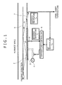
- Fig. 1 is a sectional view taken in a direction in which a sheet is passed and a control flow diagram of assistance in explaining the outline of the construction of a temperature measuring apparatus employing the first means for measuring the temperature of a steel sheet.
- a reference plate 1 is disposed opposite to a steel sheet 1 so as to extend parallel to the steel sheet 1.
- the temperature measuring methods using multiple reflection mentioned in Patent documents 2, 3 and 5 need the reflecting plate disposed at an inclination to the steel sheet to cause reflection a predetermined times for multiple reflection.
- the reference plate 2 of the present invention can diminish measurement error by increasing the view factors F12 and F21 of Expression (13) as close as to 1. Therefore, it is desirable to dispose the reference plate parallel to the objective steel sheet and as close as possible to the steel sheet so that the reference plate has a maximum view factor.
- the steel sheet 1 meanders vertically (waves). Therefore, the reference plate 2 needs to be separated from the steel sheet 1 by a space having a predetermined size.
- a built-in heater 3 is incorporated into the reference plate 2 to control the temperature of the reference plate 2.
- the heater 3 can be heated by a power source 4 provided with a temperature controller 5.
- the temperature controller 5 regulates the output of the heater power source 4 on the basis of temperature T 2 of the reference plate 2 measured by the contact thermometer 6 so that the temperature T 2 is equal to a predetermined temperature, which will be described later.
- a set initial temperature for the temperature T 2 of the reference plate 2 is, for example, a desired temperature To of the steel sheet 1. It is desirable that the measured temperature T 2 of the reference plate 2 is the mean of temperatures measured by plural contact thermometer 6 placed in contact with the reference plate 2.
- the radiation pyrometer 7 is directed toward a surface of the steel sheet 1 to receive the radiosity of the steel sheet 1 through the space between the reference plate 2 and the steel sheet 1.
- the angle ⁇ of the thermal pyrometer 7 to the surface of the steel sheet 1 is adjusted such that alternate reflection of radiation energy by the reference plate and the objective steel sheet occurs once or twice.
- Each of the reference plate 2 and the steel sheet 1 is desired to reflect radiation energy at least once, because radiation energy from the background, such as the wall of the furnace, is reflected directly by the steel sheet 1 as part of the radiosity of the steel sheet 1 (reflected energy) and measurement error increases if radiation energy is received by the radiation pyrometer without being reflected by the reference plate 2.
- the angle ⁇ between the radiation pyrometer 7 and the steel sheet 1 may be properly adjusted such that the reflection of radiation energy between the reference plate 2 and the steel sheet 1 occurs once or twice according to the size of the reference plate 2 and the distance between the steel sheet 1 and the reference plate 2.
- the angle ⁇ is 5° or above and below 60°, more desirably, in the range of 10° to 50°, most desirably, in the range of 20° to 40°.
- the radiosity of the steel sheet 1 is measured by the radiation pyrometer 7.
- the relation between radiation energy measured by the radiation pyrometer 7 and the radiosity of the steel sheet 1 is expressed by:
- radiosity temperature T g (temperature indicated by the radiation pyrometer) corresponding to the temperature of a blackbody that radiate energy equivalent to the radiosity G 1 of the steel sheet can be measured by setting view factor F g from the steel sheet to the radiation pyrometer to the emissivity ⁇ r for the radiation pyrometer 7.
- the view factor F g can be theoretically determined because the view factor F g from the steel sheet to the radiation pyrometer is dependent on the respective geometrical shapes of the steel sheet and the radiation pyrometer, the positional relation between the steel sheet and the radiation pyrometer and the directional emissivity of the steel sheet.
- the view factor F g can be determined, for example, through off-line experiments using the same view factor and positional relation.
- the radiation-pyrometer-indicated temperature (radiosity temperature) T g measured by the radiation pyrometer 7 is given as a set temperature for the reference plate temperature T 2 to the temperature controller 5.
- the output of the heater power source 4 is regulated such that the reference plate temperature T 2 coincides with the radiosity temperature T g .
- Accurate steel sheet temperature control can be achieved by controlling a heating device for heating the steel sheet or a cooling device for cooling the steel sheet so as to make the steel sheet temperature T 1 coincide with a desired temperature To of steel sheet.
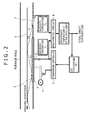
- Fig. 2 is a sectional view taken in a direction in which a sheet is passed and a control flow diagram of assistance in explaining the outline of the construction of a temperature measuring apparatus in an embodiment employing the second means for measuring the temperature of a steel sheet.
- this embodiment is built by adding an arithmetic circuit for calculating the temperature of a steel sheet (hereinafter, referred to simply as "arithmetic circuit") 8 to the construction of the foregoing first embodiment ( Fig. 1 ).
- arithmetic circuit for calculating the temperature of a steel sheet
- Reference plate temperature T 2 measured by a contact thermometer 6 and radzataon-pyrometer-indicated temperature T g are given to the arithmetic circuit 8.
- the arithmetic circuit 8 calculates an approximate temperature T 1 ' of steel sheet temperature T 1 by using Expression (1) obtained by simplifying Expression (16).
- T ⁇ T g + K ⁇ T g - T 2
- T 2 / T g a
- Expression (1) can be obtained by replacing T 1 with T 1 '.
- K is a correction coefficient as a function of only the respective emissivities ⁇ 1 and ⁇ 2 of the steel sheet 1 and the reference plate 2 as expressed by Expression (14).
- the correction coefficient K is affected by the variation of the respective emissivities of the steel sheet 1 and the reference plate 2.
- an error resulting from the correction coefficient K is eliminated and accurate measurement of the temperature of the steel sheet 1 can be achieved because the reference plate temperature T 2 is controlled so as to coincide with the radiosity temperature T g .
- the value of the correction coefficient K dose not need to be exactly set.
- the value of the correction coefficient K needs to be accurate to some degree because the correction coefficient K has influence on time in which the measured steel sheet temperature reaches a predetermined accuracy. Therefore, values determined through off-line measurement or means in ranges of variation expected from values mentioned in a literature are employed as the estimated values of the respective emissivities ⁇ 1 and ⁇ 2 of the steel sheet 1 and the reference plate 2.
- the value of the correction coefficient K may be a value obtained through calculation using Expression (14) and those estimated values of the respective emissivities ⁇ 1 and ⁇ 2 of the steel sheet 1 and the reference plate 2.
- the approximate temperature T 1 ' of the steel sheet calculated by the arithmetic circuit 8 is given as a set value of the reference plate temperature T 2 to the temperature controlled 5.
- the output of the heater power source 4 is regulated so as to make the reference plate temperature T 2 coincide with T 1 '. Since the difference ⁇ T between T 2 and T g decreases gradually and approaches 0, steel sheet temperature can be accurately measured by a measuring method that regards T 1 ' as steel sheet temperature T 1 .
- this embodiment as compared with the first embodiment, additionally needs the arithmetic circuit 8, it is expected that this embodiment can achieve the accurate steel sheet temperature measurement more quickly than the method in the first embodiment by directly controlling the reference plate temperature T 2 to make the reference plate temperature T 2 approach the approximate value T 1 ' of the steel sheet temperature T 1 .
- Accurate measurement of the steel sheet temperature can be achieved without using a computer capable of high-speed computation as the arithmetic circuit 8 and without sacrificing response characteristic by using Expression (1), which is a simple linear expression.
- Fig. 3 is a sectional view taken in a direction in which a sheet is passed and a control flow diagram of assistance in explaining the outline of the construction of a temperature measuring apparatus employing the third means for measuring the temperature of a steel sheet.
- this embodiment uses a desired temperature To of a steel sheet, namely, a fixed value, as a set temperature given to a temperature controller 5 instead of the radiation-pyrometer-indicated temperature (radiosity temperature) Tg used by the first embodiment shown in Fig. 1 .
- This embodiment takes a radiation-pyrometer-indicated temperature (radiosity temperature) T g directly for the steel sheet temperature T 1 without executing control operations.
- the steel sheet temperature T 1 includes a measurement error when the radiosity temperature T g and the reference plate temperature T 2 are not equal to each other.
- the set reference plate temperature T 2 is equal to the desired temperature T 0 of the steel sheet and the actual steel sheet temperature T 1 is controlled so as to coincide with the desired temperature T 0 of the steel sheet. Therefore, the radiosity temperature T g approaches the desired temperature T 0 of the steel sheet and the measurement error is not very large. Since the reference plate temperature T 2 does not need to be controlled, the reference plate temperature T 2 can be set to the desired temperature T 0 of the steel sheet beforehand before starting passing the steel sheet. Thus, the measured steel sheet temperature T 1 can be obtained more quickly.
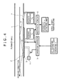
- Fig. 4 is a sectional view taken in a direction in which a sheet is passed and a control flow diagram of assistance in explaining the outline of the construction of another temperature measuring apparatus employing the third means for measuring the temperature of a steel sheet.
- this embodiment is built by adding an arithmetic circuit 8 for calculating the temperature of a steel sheet to the construction of the foregoing third embodiment ( Fig. 3 ).
- This embodiment similarly to the third embodiment, sets the reference plate temperature T 2 to a desired temperature T 0 of the steel sheet and, similarly to the second embodiment, gives a radiation-pyrometer-indicated temperature T g and a reference plate temperature T 2 measured by a contact thermometer 6 to the arithmetic circuit 8.
- the arithmetic circuit 8 calculates an approximate temperature T 1 ' of the steel sheet temperature T 1 by using Expression (1).
- the calculated approximate temperature T 1 ' may be used as a steel sheet temperature T 1 .
- this embodiment can determine a steel sheet temperature accurately even if the actual steel sheet temperature T 1 is different from the desired temperature T 0 of the steel sheet.
- Expression (2) may be used for calculating the approximate temperature T 1 ' of the steel sheet temperature instead of Expression (1) used by the second and the fourth embodiment.
- T 1 ⁇ ⁇ F ⁇ T g + K ⁇ T g - T 2
- F is a coefficient dependent on the respective view factors of a reference plate 2 and a steel sheet 1, and the positional relation between the reference plate 2 and the steel sheet 1.
- E T 1 F 21 G 1 + K ⁇ G 1 - E T 2
- the steel sheet temperature can be measured still more accurately by using Expression (2) instead of Expression (1).
- a desired temperature of a steel sheet for a heat treatment process including heating or cooling is changed stepwise as shown in Fig. 5 to provide steel sheets of different qualities with different mechanical properties, such as strength and elongation, and different plating characteristics, such as degree of alloying. Therefore, the reference plate temperature T 2 needs to be changed according to the change of the desired temperature To of the steel sheet when the present invention is applied to those systems. Delay in response occurs necessarily in changing the desired temperature T 0 of the steel sheet as shown in Fig. 5 .
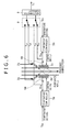
- two reference plates 2a and 2b are disposed in a furnace, temperature controllers 5a and 5b, contact thermometers 6a and 6b and radiation pyrometers 7a and 7b are used, one arithmetic circuit 8 for calculating steel sheet temperature is used, and a switching circuit 9 capable of giving reference plate temperatures T 2a and T 2b measured, respectively, by the reference plates 2a and 2b alternately to the arithmetic circuit 8 for calculating steel sheet temperature and of giving the radiosity temperatures T ga and T gb measured, respectively, by the radiation pyrometers 7a and 7b alternately to the arithmetic circuit 8 for calculating steel sheet temperature is used.
- the heater 3 is used by way of example as a heating means for regulating the temperature of the reference plate 2.
- a cooling means such as an air-cooling device or a water-cooling device, may be used in addition to the heating means. Use of both the heating means and the cooling means enables still quicker control of the reference plate temperature T 2 .
- thermometer such as a thermocouple
- the contact thermometer is used by way of example as a thermometer by the first to the sixth embodiment for directly measuring the temperature of the reference plate 2
- thermometer is not limited thereto.
- a noncontact thermometer including a thermocouple placed in a cavity may be used.
- the first to the third embodiment regard the T g or T 1 ' as the steel sheet temperature while the reference plate temperature T 2 is being controlled. It is possible to execute a closed-loop control that takes T g or T 1 ' for the steel plate temperature when the difference ⁇ T between T 2 and T g or T 1 ' decreases below a predetermined value, such as 5°C.
- the two reference plates 2a and 2b are disposed on the opposite sides, respectively, of the steel sheet 1.
- the two reference plates 2a and 2b may be arranged in a steel sheet passing direction.
- the embodiment is provided with the two reference plates by way of example.
- the embodiment may be provided with three or more reference plates and those plates may be used by turns.
- the reference plates 2a and 2b are provided with the radiation pyrometers 7, respectively, by way of example.
- One radiation pyrometer 7 may be moved alternately to the two reference plates 2a and 2b.
- the switching circuit connects the combinations each of the reference plate 2 and the radiation pyrometer 7 selectively to the arithmetic circuit 8.
- the switching circuit may be omitted and the combinations each of the reference plate and the radiation pyrometer may be connected to arithmetic circuits 8 for calculating steel sheet temperature, respectively.
Landscapes
- Physics & Mathematics (AREA)
- General Physics & Mathematics (AREA)
- Spectroscopy & Molecular Physics (AREA)
- Engineering & Computer Science (AREA)
- Automation & Control Theory (AREA)
- Radiation Pyrometers (AREA)
Abstract
Description
- The present invention relates to a method of measuring the temperature of a steel sheet without touching the steel sheet and an apparatus for carrying out the method intended to be applied to, for example, a continuous annealing system and an alloy hot dip galvanizing system.
- A variety of steel sheets are processed continuously by a continuous annealing system for continuously processing steel sheets by a heat treatment and an alloy hot dip galvanizing system for processing hot dip galvanized steel sheets by an alloying process. It is important to control the process such that the temperature of the steel sheet after a heat treatment process including heating and cooling is adjusted accurately to a desired temperature for stabilizing the mechanical characteristics, such as strength and elongation, and the plating characteristics, such as alloying degree, of different steel sheets.
- Generally, a noncontact radiation pyrometer is used for measuring the temperature of the steel sheets continuously moving in those systems. The emissivity of the steel sheet, namely, an object of measurement, needs to be determined when the radiation pyrometer is used. Emissivity of the steel sheet is dependent on the physical properties, such as quality and surface characteristic, and temperature. Therefore, it is difficult to determine the emissivity of the steel sheet on the basis of those variable factors. Thus, a measurement error appears easily in the measurement of the temperature of the steel sheet and, consequently, control for accurately adjusting the temperature of the steel sheet to a desired temperature cannot be achieved.
- Various measuring methods having the least possible susceptibility to the variation of the emissivity of the steel sheet have been proposed. Those measuring methods use multiple reflection on the basis of knowledge that multiple reflection increases an apparent emissivity.
- A cavity method mentioned in
Patent document 1 places two types of cylindrical cavities respectively having inside surfaces having high reflectivity nearly equal to that of a mirror surface near a steel sheet, compares radiant energy passed through a first cavity making multiple reflection and radiant energy passed through a second cavity without making multiple reflection to determine the temperature and thermal emissivity of the steel sheet. This cavity method needs the two cylindrical cavities, which needs a large space. - Measuring methods using multiple reflection between a steel sheet and a reflecting plate and not needing a large space have been proposed.
- A measuring method mentioned in
Patent document 2 places a reflecting plate at an inclination to a steel sheet, and takes a temperature indicated by a radiation thermometer as the temperature of the steel sheet, regarding radiant energy of multiple reflection between the steel sheet and the reflecting plate as blackbody radiant energy. - A measuring method mentioned in
Patent document 3 determines the emissivity of a steel sheet on the basis of radiant energy determined by a measuring method similar to that mentioned inPatent document 2. - The measuring methods mentioned in
Patent documents 2 and 3 (including the cavity method mentioned in Patent document 1) are based on the fact that the radiant energy of the reflecting plate is far less the radiant energy of multiple reflection when the reflecting plate is at an ordinary temperature or a low temperature and that the effect of the variation of the emissivity of the steel plate on the radiant energy of multiple reflection is ignorable when the reflecting plate has a high reflectivity, i.e., the emissivity is lower than that determined by the Kirchhoff's law, or when the reflectivity (emissivity) of the steel sheet is known. Therefore, the measuring methods mentioned inPatent documents 2 and 3 (including the cavity method mentioned in Patent document 1) need to maintain the reflectivity of the reflecting plate at a high level, i.e., to maintain the surface of the reflecting plate in a mirror surface, or to maintain the known reflectivity of the reflecting plate for a long time. Since the reflectivity (emissivity) of the reflecting plate changes due to the oxidation of the surface of the reflecting plate, it is difficult to maintain accuracy stably for a long time. Similar matters are mentioned inPatent document 5, which will be described later. - To solve those problems, a measuring method mentioned in
Patent document 4 achieves the measurement of the temperature of a steel sheet regardless of the influence of the emissivity of the steel sheet by causing multiple reflection between the steel sheets. This measuring method uses a basic physical phenomenon that apparent emissivity increases when multiple reflection occurs within an object of measurement, does not use any reflecting plate and is not subject to the influence of the reflectivity (emissivity) of a reflecting plate. Since the apparent emissivity is approximately 1 even if the emissivity of the steel sheet varies, measurements obtained by this measuring method include a small error and this measuring method is scarcely subject to aging. However, this measuring method can be used for measurement only at a limited measuring position where parts of a steel sheet running between upper and lower hearth rollers of a vertical furnace face each other because this measuring method uses multiple reflection between parts of the steel sheet. - A measuring method mentioned in
Patent document 5 was developed by incorporating improvements into the measuring method mentioned inPatent document 3. The measuring method mentioned inPatent document 5 intends to ensure the improvement of measurement accuracy by employing a function to maintain a reflecting plate at a fixed temperature even if the reflectivity (emissivity) of the reflecting plate changes with time. - As mentioned in
Patent document 3, reflection needs to be repeated predetermined times between the reflection plate and the steel sheet for multiple reflection. The radiation pyrometer inevitably needs a large reflecting plate to ensure the necessary times of reflection when the radiation pyrometer is disposed at a small angle (the angle θ inFig. 2 of Patent document 3). The measuring method mentioned inPatent document 5 needs to set the reflecting plate at a proper temperature according to the emissivity and temperature of the steel sheet and the emissivity of the reflection plate to control the steel sheet accurately at a desired temperature. Thus, it is difficult to control the steel sheet accurately and stably at a desired temperature for a long period of time.
Patent document 1:JP S54-85079 A
Patent document 2:JP 259-87329 A
Patent document 3:JP S59-111026 A
Patent document 4:JP S60-86432 A
Patent document 5:JP H5-203497 A - Accordingly, it is an object of the present invention to provide a method capable of accurately measuring the temperature of a steel sheet for a long period of time without being affected by the time-dependent change of the emissivity of a reflecting plate (referred to as "reference plate" in the present invention) and the variation of the emissivity of the steel sheet and of being carried out by a measuring apparatus capable of being easily installed as compared with a measuring apparatus for carrying out the foregoing measuring method using multiple reflection, a measuring apparatus for carrying out the measuring method, and a temperature control method using the measuring method and capable of still more accurately controlling the temperature of the steel sheet.
- The inventors of the present invention made the following studies on an assumption that the foregoing problems can be solved by using the radiosity, namely, the sum of radiation energy and reflection energy, of an objective steel sheet (sometimes, referred to simply as "steel sheet").
- The radiosities of two steel sheet, namely, two finite flat sheet, are expressed by Expressions (11 and 12) ignoring background radiation from the surroundings.


Where: - ε1 and ε2: Respective emissivities of steel sheet and reference plate
- T1 and T2: Respective absolute temperatures of steel sheet and reference plate
- E(T) = σT4: Blackbody radiation energy at T (per unit area)
- σ: Stefan-Boltzmann's constant
- G1 and G2: Respective radiosities of steel sheet and reference plate (per unit area)
- In Expressions (11) and (12), F12 is view factor when the reference plate is viewed from the steel sheet and F21 is view factor when the steel sheet is viewed from the reference plate. The view factors F12 and F21 are dependent on the respective geometric shapes of the steel sheet and the reference plate.
- Expression (13) for calculating the blackbody radiation energy of the objective steel sheet is obtained by substituting Expression (12) into expression (11) to eliminate G2.

- In Expression (13), K is a correction coefficient defined by Expression (14) and dependent on the respective emissivities of the objective steel sheet and the reference plate.

- When both F12 and F21 are substantially equal to 1, Expression (13) can be converted into Expression (15) on an assumption that F12 = F21 = 1.

- The relation between the radiosity G1 of the steel sheet and the temperature Tg of a blackbody that radiates energy equivalent to that radiated by the steel sheet (hereinafter, referred to as "radiosity temperature") is expressed by G1 = σTg 4. Thus, Expression (16) is derived from Expression (15).

The temperature T1 of the steel sheet can be calculated by substituting the radiosity temperature Tg and the temperature T2 of the reference plate into Expression (16). - As shown by Expression (14), the correction coefficient K is a function of the respective emissivities ε1 and ε2 of the steel sheet and the reference plate. Therefore, the right member of Expression (16) is a function of the respective emissivities of the steel sheet and the reference plate. When Tg ≠ T2, the temperature T1 of the steel sheet calculated by using Expression (16) includes a measurement error.
- The inventors of the present invention made further studies to provide means for reducing the measurement error to the smallest possible value and developed the following first to third means.
- The first means executes closed-loop control to make the temperature T2 of the reference plate coincide with the radiosity temperature Tg by heating or cooling the reference plate by a temperature controller. This causes the second term, K (Tg 4 - T2 4), of the right member of Expression (16) to
approach 0. Consequently, Expression (16) is converted to T1 4 = Tg4, i.e., T1 = Tg, after convergence, and the temperature T1 of the steel sheet is determined without being affected by the accuracy of the correction coefficient K. - The second means, similarly to the first means, executes the closed-loop control of the temperature T2 of the reference plate to make the temperature T2 of the reference place coincide with an approximation T1' of the temperature T1 of the steel sheet calculated by using Expression (1) or (2) obtained by simplifying Expression (16) instead of coinciding with the radiosity temperature Tg. Consequently, the temperature T2 of the reference plate approaches the temperature T1 of the steel sheet more quickly. Thus, convergence can be quickly achieved.
- The third means, differing from the first and the second means, sets a desired temperature T0 of the steel sheet instead of executing a closed-loop control such that the temperature T2 of the reference plate coincides with the radiosity temperature Tg or the approximation T1' of the temperature T1 of the steel sheet. Thus, the temperature T2 of the reference plate can be previously adjusted to the desired temperature T0 of the steel sheet and time needed to carry out closed-loop control omitted, and hence the accurate temperature of the steel sheet can be quickly determined.
- The present invention made on the basis of the foregoing findings has the following gist.
- A temperature measuring method of measuring the temperature of a steel sheet in a first aspect of the present invention includes the steps of: disposing a reference plate provided with a temperature controller opposite to an objective steel sheet; directly measuring the reference plate temperature T2 of the reference plate by a thermometer other than a radiation pyrometer; training a radiation pyrometer on the objective steel sheet at an angle such that alternate reflection of radiation energy by the reference plate and the objective steel sheet occurs once or twice; measuring the radiosity of the objective steel sheet by the radiation pyrometer; using a temperature obtained by converting the radiosity into a temperature of a blackbody that radiate energy equivalent to the radiosity as a radiosity temperature Tg; executing a control operation by the temperature controller to make the temperature T2 of the reference plate coincide with the radiosity temperature Tg; and using the radiosity temperature Tg as the temperature of the objective steel sheet.
- A temperature measuring method of measuring the temperature of a steel sheet in a second aspect of the present invention includes the steps of: disposing a reference plate provided with a temperature controller opposite to an objective steel sheet; directly measuring the reference plate temperature T2 of the reference plate by a thermometer other than a radiation pyrometer; training a radiation pyrometer on the objective steel sheet at an angle such that alternate reflection of radiation energy by the reference plate and the objective steel sheet occurs once or twice; measuring the radiosity of the objective steel sheet by the radiation pyrometer; using a temperature obtained by converting the radiosity into a temperature of a blackbody that radiate energy equivalent to the radiosity as a radiosity temperature Tg; calculating an approximate temperature T1' of the steel sheet by using:

where K is a correction coefficient determined on the basis of the respective radiosities of the reference plate and the objective steel sheet obtained by measurement or mentioned in a literature; executing a control operation by the temperature controller to make the reference plate temperature T2 coincide with the approximate temperature T1' of the steel sheet temperature; and using the approximate temperature T1' as the temperature of the objective steel sheet. - A temperature measuring method of measuring the temperature of a steel sheet in a third aspect of the present invention includes the steps of: disposing a reference plate provided with a temperature controller opposite to an objective steel sheet; executing a control operation by the temperature controller to make the reference plate temperature T2 of the reference plate measured by a thermometer other than a radiation pyrometer coincide with a desired temperature To of the steel sheet; training a radiation pyrometer on the objective steel sheet at an angle such that alternate reflection of radiation energy by the reference plate and the objective steel sheet occurs once or twice; measuring the radiosity of the objective steel sheet by the radiation pyrometer; using a temperature obtained by converting the radiosity into a temperature of a blackbody that radiate energy equivalent to the radiosity as a radiosity temperature Tg; and using the radiosity temperature Tg as the steel sheet temperature of the objective steel sheet.
- A temperature measuring method of measuring the temperature of a steel sheet in a fourth aspect of the present invention includes the steps of: disposing a reference plate provided with a temperature controller opposite to an objective steel sheet; executing a control operation by the temperature controller to make the reference plate temperature T2 of the reference plate measured by a thermometer other than a radiation pyrometer coincide with a desired temperature To of the steel sheet; training a radiation pyrometer on the objective steel sheet at an angle such that alternate reflection of radiation energy by the reference plate and the objective steel sheet occurs once or twice; measuring the radiosity of the objective steel sheet by the radiation pyrometer; using a temperature obtained by converting the radiosity into a temperature of a blackbody that radiate energy equivalent to the radiosity as a radiosity temperature Tg; and using an approximate steel sheet temperature T1' of the steel sheet calculated by using:

where K is a correction coefficient determined on the basis of the respective radiosities of the reference plate and the objective steel sheet obtained by measurement or mentioned in a literature, as the steel sheet temperature of the objective steel sheet. - The following expression may be used instead of Expression (1).

where K is a correction coefficient determined on the basis of the respective radiosities of the reference plate and the objective steel sheet obtained by measurement or mentioned in a literature, and F is a coefficient dependent on the respective geometric shapes of the reference plate and the objective steel sheet, and the positional relation between the reference plate and the objective steel sheet. - A temperature measuring apparatus for measuring the temperature of a steel sheet in a fifth aspect of the present invention including: a reference plate disposed opposite to an objective steel sheet; a temperature controller for controlling the temperature of the reference plate; a thermometer, other than a radiation pyrometer, for measuring the temperature T2 of the reference plate; a radiation pyrometer trained on the objective steel sheet at an angle such that alternate reflection of radiation energy by the reference plate and the objective steel sheet occurs once or twice to measure the radiosity of the objective steel sheet and to convert the radiosity into a radiosity temperature Tg equal to a temperature of a blackbody that radiate energy equivalent to the radiosity; and an arithmetic circuit for calculating an approximate temperature T1' of the steel sheet by using an expression:

or
where K is a correction coefficient determined on the basis of the respective radiosities of the reference plate and the objective steel sheet obtained by measurement or mentioned in a literature, and F is a coefficient dependent on the respective geometric shapes of the reference plate and the objective steel sheet, and the positional relation between the reference plate and the objective steel sheet. - Preferably, the temperature measuring apparatus includes plural sets each of the reference plate, the temperature controller and the thermometer, and the respective temperatures of the reference plates can be individually controlled.
- A control method of controlling the temperature of a steel sheet in a sixth aspect of the present invention includes the step of controlling a heating device for heating the steel sheet or a cooling device for cooling the steel sheet such that the temperature of the steel sheet measured by the foregoing temperature measuring method coincides with a desired temperature T0 of the steel sheet.
- According to the present invention, the control operation is executed to make the temperature of the reference plate coincide with the temperature based on the radiosity of the objective steel sheet measured by the radiation pyrometer (the radiosity temperature) or the desired temperature of the steel sheet, and the temperature of the steel sheet is estimated on the basis of the radiosity temperature. Therefore, the temperature measuring apparatus of the present invention can be installed more easily than the temperature measuring apparatus for carrying out the measuring method using multiple reflection, and can maintain the accurately measurement of the temperature of a steel sheet for a long period of time without being affected by the variation of the emissivity of the objective steel sheet and the change of the emissivity of the reference plate (the reflection plate of the conventional measuring apparatus) with time. An operation for heating or cooling the steel sheet is controlled by using the accurate measured temperature of the steel sheet to control the temperature of the steel sheet accurately.
-
-
Fig. 1 is a sectional view taken in a direction in which a sheet is passed and a control flow diagram in explaining the outline of the construction of a temperature measuring apparatus in a first embodiment for measuring the temperature of a steel sheet. -
Fig. 2 is a sectional view taken in a direction in which a sheet is passed and a control flow diagram in explaining the outline of the construction of a temperature measuring apparatus in a second embodiment for measuring the temperature of a steel sheet. -
Fig. 3 is a sectional view taken in a direction in which a sheet is passed and a control flow diagram in explaining the outline of the construction of a temperature measuring apparatus in a third embodiment for measuring the temperature of a steel sheet. -
Fig. 4 is a sectional view taken in a direction in which a sheet is passed and a control flow diagram in explaining the outline of the construction of a temperature measuring apparatus in a fourth embodiment for measuring the temperature of a steel sheet. -
Fig. 5 is a graph typically showing the respective modes of variation of the temperature of a reference plate, the temperature of a steel sheet, and the approximate temperature of the steel sheet when a desired temperature of the steel sheet is changed stepwise. -
Fig. 6 is a sectional view taken in a direction in which a sheet is passed and a control flow diagram in explaining the outline of the construction of a temperature measuring apparatus in a sixth embodiment for measuring the temperature of a steel sheet. -
- 1: Steel sheet
- 2: Reference plate
- 3: Heater
- 4: Heater power source
- 5: Temperature control apparatus
- 6: Contact thermometer
- 7: Thermometer (contact thermometer)
- 8: Arithmetic circuit for calculating steel sheet temperature
- 9: Selector circuit
- The present invention will be described in detail with reference to the accompanying drawings.
-
Fig. 1 is a sectional view taken in a direction in which a sheet is passed and a control flow diagram of assistance in explaining the outline of the construction of a temperature measuring apparatus employing the first means for measuring the temperature of a steel sheet. - Referring to
Fig. 1 , areference plate 1 is disposed opposite to asteel sheet 1 so as to extend parallel to thesteel sheet 1. The temperature measuring methods using multiple reflection mentioned inPatent documents reference plate 2 of the present invention can diminish measurement error by increasing the view factors F12 and F21 of Expression (13) as close as to 1. Therefore, it is desirable to dispose the reference plate parallel to the objective steel sheet and as close as possible to the steel sheet so that the reference plate has a maximum view factor. In some cases, thesteel sheet 1 meanders vertically (waves). Therefore, thereference plate 2 needs to be separated from thesteel sheet 1 by a space having a predetermined size. - A built-in
heater 3 is incorporated into thereference plate 2 to control the temperature of thereference plate 2. Theheater 3 can be heated by apower source 4 provided with atemperature controller 5. - A
contact thermometer 6 for directly measuring the temperature of thereference plate 2, such as a thermocouple, namely, a thermometer employed in addition to aradiation pyrometer 7, is placed in contact with thereference plate 2. Thetemperature controller 5 regulates the output of theheater power source 4 on the basis of temperature T2 of thereference plate 2 measured by thecontact thermometer 6 so that the temperature T2 is equal to a predetermined temperature, which will be described later. A set initial temperature for the temperature T2 of thereference plate 2 is, for example, a desired temperature To of thesteel sheet 1. It is desirable that the measured temperature T2 of thereference plate 2 is the mean of temperatures measured byplural contact thermometer 6 placed in contact with thereference plate 2. - The
radiation pyrometer 7 is directed toward a surface of thesteel sheet 1 to receive the radiosity of thesteel sheet 1 through the space between thereference plate 2 and thesteel sheet 1. The angle θ of thethermal pyrometer 7 to the surface of thesteel sheet 1 is adjusted such that alternate reflection of radiation energy by the reference plate and the objective steel sheet occurs once or twice. Each of thereference plate 2 and thesteel sheet 1 is desired to reflect radiation energy at least once, because radiation energy from the background, such as the wall of the furnace, is reflected directly by thesteel sheet 1 as part of the radiosity of the steel sheet 1 (reflected energy) and measurement error increases if radiation energy is received by the radiation pyrometer without being reflected by thereference plate 2. When radiation energy reflected at least once by thereference plate 2 is reflected by thesteel sheet 1, the influence of the radiation energy from the background is reduced to an ignorable extent and measurement error can be satisfactorily diminished. Reflection of radiation energy between thereference plate 2 and the steel sheet is desired to occur twice at the most because the influence of radiation energy from the background is reduced satisfactorily before the radiation energy is reflected three times and further reflection of the radiation energy is scarcely effective in diminishing measurement error, and a large reference plate is necessary to cause reflection of the radiation energy three times or above. - The angle θ between the
radiation pyrometer 7 and thesteel sheet 1 may be properly adjusted such that the reflection of radiation energy between thereference plate 2 and thesteel sheet 1 occurs once or twice according to the size of thereference plate 2 and the distance between thesteel sheet 1 and thereference plate 2. In view of facilitating receiving radiosity by increasing the directional emissivity of thesteel sheet 1 and restrictions on a space for installing theradiation pyrometer 7 placed by the facilities, it is desirable that the angle θ is 5° or above and below 60°, more desirably, in the range of 10° to 50°, most desirably, in the range of 20° to 40°. - The radiosity of the
steel sheet 1 is measured by theradiation pyrometer 7. The relation between radiation energy measured by theradiation pyrometer 7 and the radiosity of thesteel sheet 1 is expressed by: - FgG1 = εrEr
- Fg: View factor from the steel sheet to the radiation pyrometer
- Er: Blackbody energy measured by the radiation pyrometer
- εr: Emissivity set for the radiation pyrometer.
- Since G1 = Er when Fg = εr, radiosity temperature Tg (temperature indicated by the radiation pyrometer) corresponding to the temperature of a blackbody that radiate energy equivalent to the radiosity G1 of the steel sheet can be measured by setting view factor Fg from the steel sheet to the radiation pyrometer to the emissivity εr for the
radiation pyrometer 7. - The view factor Fg can be theoretically determined because the view factor Fg from the steel sheet to the radiation pyrometer is dependent on the respective geometrical shapes of the steel sheet and the radiation pyrometer, the positional relation between the steel sheet and the radiation pyrometer and the directional emissivity of the steel sheet. The view factor Fg can be determined, for example, through off-line experiments using the same view factor and positional relation.
- The radiation-pyrometer-indicated temperature (radiosity temperature) Tg measured by the
radiation pyrometer 7 is given as a set temperature for the reference plate temperature T2 to thetemperature controller 5. The output of theheater power source 4 is regulated such that the reference plate temperature T2 coincides with the radiosity temperature Tg. The radiosity temperature Tg changes while the output of thepower source 4 is controlled so that T2 coincides with Tg and, eventually, T2 converges and T2 = Tg is achieved. Since the difference ΔT between T2 and Tg decreases gradually and approaches 0, steel sheet temperature can be accurately measured by a measuring method that regards Tg as steel sheet temperature T1. Accurate steel sheet temperature control can be achieved by controlling a heating device for heating the steel sheet or a cooling device for cooling the steel sheet so as to make the steel sheet temperature T1 coincide with a desired temperature To of steel sheet. -
Fig. 2 is a sectional view taken in a direction in which a sheet is passed and a control flow diagram of assistance in explaining the outline of the construction of a temperature measuring apparatus in an embodiment employing the second means for measuring the temperature of a steel sheet. - As shown in
Fig. 2 , this embodiment is built by adding an arithmetic circuit for calculating the temperature of a steel sheet (hereinafter, referred to simply as "arithmetic circuit") 8 to the construction of the foregoing first embodiment (Fig. 1 ). - Procedures for measuring reference plate temperature T2 sand radiation-pyrometer-indicated temperature (radiosity temperature) Tg are similar to those executed by the foregoing embodiment and hence the description thereof will be omitted.
- Reference plate temperature T2 measured by a
contact thermometer 6 and radzataon-pyrometer-indicated temperature Tg are given to thearithmetic circuit 8. Thearithmetic circuit 8 calculates an approximate temperature T1' of steel sheet temperature T1 by using Expression (1) obtained by simplifying Expression (16). -

- A procedure for deriving Expressions (1) from Expression (16) will be described.
- From Expression (16),


- Therefore,

- When


- Therefore,

Thus, Expression (1) can be obtained by replacing T1 with T1'. - In Expression (1), K is a correction coefficient as a function of only the respective emissivities ε1 and ε2 of the
steel sheet 1 and thereference plate 2 as expressed by Expression (14). Thus, the correction coefficient K is affected by the variation of the respective emissivities of thesteel sheet 1 and thereference plate 2. However, an error resulting from the correction coefficient K is eliminated and accurate measurement of the temperature of thesteel sheet 1 can be achieved because the reference plate temperature T2 is controlled so as to coincide with the radiosity temperature Tg. - Accordingly, the value of the correction coefficient K dose not need to be exactly set. However, the value of the correction coefficient K needs to be accurate to some degree because the correction coefficient K has influence on time in which the measured steel sheet temperature reaches a predetermined accuracy. Therefore, values determined through off-line measurement or means in ranges of variation expected from values mentioned in a literature are employed as the estimated values of the respective emissivities ε1 and ε2 of the
steel sheet 1 and thereference plate 2. The value of the correction coefficient K may be a value obtained through calculation using Expression (14) and those estimated values of the respective emissivities ε1 and ε2 of thesteel sheet 1 and thereference plate 2. - The approximate temperature T1' of the steel sheet calculated by the
arithmetic circuit 8 is given as a set value of the reference plate temperature T2 to the temperature controlled 5. The output of theheater power source 4 is regulated so as to make the reference plate temperature T2 coincide with T1'. Since the difference ΔT between T2 and Tg decreases gradually and approaches 0, steel sheet temperature can be accurately measured by a measuring method that regards T1' as steel sheet temperature T1. - Although this embodiment, as compared with the first embodiment, additionally needs the
arithmetic circuit 8, it is expected that this embodiment can achieve the accurate steel sheet temperature measurement more quickly than the method in the first embodiment by directly controlling the reference plate temperature T2 to make the reference plate temperature T2 approach the approximate value T1' of the steel sheet temperature T1. Accurate measurement of the steel sheet temperature can be achieved without using a computer capable of high-speed computation as thearithmetic circuit 8 and without sacrificing response characteristic by using Expression (1), which is a simple linear expression. -
Fig. 3 is a sectional view taken in a direction in which a sheet is passed and a control flow diagram of assistance in explaining the outline of the construction of a temperature measuring apparatus employing the third means for measuring the temperature of a steel sheet. - As shown in
Fig. 3 , this embodiment uses a desired temperature To of a steel sheet, namely, a fixed value, as a set temperature given to atemperature controller 5 instead of the radiation-pyrometer-indicated temperature (radiosity temperature) Tg used by the first embodiment shown inFig. 1 . This embodiment takes a radiation-pyrometer-indicated temperature (radiosity temperature) Tg directly for the steel sheet temperature T1 without executing control operations. As obvious from Expression (16), in this embodiment, the steel sheet temperature T1 includes a measurement error when the radiosity temperature Tg and the reference plate temperature T2 are not equal to each other. The set reference plate temperature T2 is equal to the desired temperature T0 of the steel sheet and the actual steel sheet temperature T1 is controlled so as to coincide with the desired temperature T0 of the steel sheet. Therefore, the radiosity temperature Tg approaches the desired temperature T0 of the steel sheet and the measurement error is not very large. Since the reference plate temperature T2 does not need to be controlled, the reference plate temperature T2 can be set to the desired temperature T0 of the steel sheet beforehand before starting passing the steel sheet. Thus, the measured steel sheet temperature T1 can be obtained more quickly. -
Fig. 4 is a sectional view taken in a direction in which a sheet is passed and a control flow diagram of assistance in explaining the outline of the construction of another temperature measuring apparatus employing the third means for measuring the temperature of a steel sheet. - As shown in
Fig. 4 , this embodiment is built by adding anarithmetic circuit 8 for calculating the temperature of a steel sheet to the construction of the foregoing third embodiment (Fig. 3 ). - This embodiment, similarly to the third embodiment, sets the reference plate temperature T2 to a desired temperature T0 of the steel sheet and, similarly to the second embodiment, gives a radiation-pyrometer-indicated temperature Tg and a reference plate temperature T2 measured by a
contact thermometer 6 to thearithmetic circuit 8. Thearithmetic circuit 8 calculates an approximate temperature T1' of the steel sheet temperature T1 by using Expression (1). The calculated approximate temperature T1' may be used as a steel sheet temperature T1. - Although this embodiment, as compared with the third embodiment, additionally needs the
arithmetic circuit 8, this embodiment can determine a steel sheet temperature accurately even if the actual steel sheet temperature T1 is different from the desired temperature T0 of the steel sheet. - Expression (2) may be used for calculating the approximate temperature T1' of the steel sheet temperature instead of Expression (1) used by the second and the fourth embodiment.
-

where F is a coefficient dependent on the respective view factors of areference plate 2 and asteel sheet 1, and the positional relation between thereference plate 2 and thesteel sheet 1. - A process of obtaining Expression (2) will be described.
- Expression (13) can be simplified to obtain the following expression when F21 cannot be considered to be substantially equal to 1 but is close to 1 due to the variation of the geometric relation between the
steel sheet 1 and thereference plate 2, for example, when the width of the steel sheet is changed greatly even though the value of F12 of Expression (13) is substantially equal to 1, by assuming that F12F21 = F21 and (1 - F12F21)/(ε1 + ε2 - ε1ε2) = 0. -

- If it is assumed that F21 = F4 in this expression, the following expression is obtained by the same process as that of obtaining Expression (1).

Expression (2) is obtained by replacing T1 with T1'. - The view factor F12 can be theoretically calculated on the basis of only the geometric relation between two surfaces (Nippon Kikai Gakkai, "Dennetsu Kougaku Shiryou 4th edition", Maruzen, Oct., 1986, Expression (7), p. 159). Therefore, F is defined univocally by F= F21 1/4. The steel sheet temperature can be measured still more accurately by using Expression (2) instead of Expression (1).
- In a continuous annealing system and a hot dip galvanizing system that process a
steel sheet 1 continuously by a heat treatment process, a desired temperature of a steel sheet for a heat treatment process including heating or cooling is changed stepwise as shown inFig. 5 to provide steel sheets of different qualities with different mechanical properties, such as strength and elongation, and different plating characteristics, such as degree of alloying. Therefore, the reference plate temperature T2 needs to be changed according to the change of the desired temperature To of the steel sheet when the present invention is applied to those systems. Delay in response occurs necessarily in changing the desired temperature T0 of the steel sheet as shown inFig. 5 . When the steel sheet is maintained at the desired temperature for a short period of time, a control operation for changing the present desired temperature for the next desired temperature of the steel sheet is executed before the reference plate temperature T2 reaches the desired temperature of the steel sheet. Therefore, it takes time for the steel sheet temperature T1 calculated by using Expression (16) and the approximate value T1' of the steel sheet temperature calculated by using Expression (1) to reach the desired temperature T0 of the steel sheet. Consequently, the present desired temperature of the steel sheet is changed for the next desired temperature of the steel sheet before the desired temperature T0 is reached and the accuracy of measurement of the temperature of the steel sheet worsens. - Accordingly, as shown in
Fig. 6 , tworeference plates temperature controllers contact thermometers 6a and 6b andradiation pyrometers arithmetic circuit 8 for calculating steel sheet temperature is used, and aswitching circuit 9 capable of giving reference plate temperatures T2a and T2b measured, respectively, by thereference plates arithmetic circuit 8 for calculating steel sheet temperature and of giving the radiosity temperatures Tga and Tgb measured, respectively, by theradiation pyrometers arithmetic circuit 8 for calculating steel sheet temperature is used. When a steel sheet 1b different in desired temperature from the presently processed steel sheet 1a is to be passed continuously, it is recommended to set thereference plate 2b other than the presently usedreference plate 2a beforehand so as to be heated at a desired temperature of the steel sheet 1b and to set theswitching circuit 9 so as to connect thereference plate 2b and theradiation pyrometer 7b to thearithmetic circuit 8. - In the first to the sixth embodiment, the
heater 3 is used by way of example as a heating means for regulating the temperature of thereference plate 2. A cooling means, such as an air-cooling device or a water-cooling device, may be used in addition to the heating means. Use of both the heating means and the cooling means enables still quicker control of the reference plate temperature T2. - Although the contact thermometer, such as a thermocouple, is used by way of example as a thermometer by the first to the sixth embodiment for directly measuring the temperature of the
reference plate 2, the thermometer is not limited thereto. For example, a noncontact thermometer including a thermocouple placed in a cavity may be used. - The first to the third embodiment regard the Tg or T1' as the steel sheet temperature while the reference plate temperature T2 is being controlled. It is possible to execute a closed-loop control that takes Tg or T1' for the steel plate temperature when the difference ΔT between T2 and Tg or T1' decreases below a predetermined value, such as 5°C.
- In the sixth embodiment, the two
reference plates steel sheet 1. The tworeference plates - The embodiment is provided with the two reference plates by way of example. The embodiment may be provided with three or more reference plates and those plates may be used by turns.
- The
reference plates radiation pyrometers 7, respectively, by way of example. Oneradiation pyrometer 7 may be moved alternately to the tworeference plates - In the embodiment described above by way of example is provided with only the single
arithmetic circuit 8 for calculating steel sheet temperature, and the switching circuit connects the combinations each of thereference plate 2 and theradiation pyrometer 7 selectively to thearithmetic circuit 8. The switching circuit may be omitted and the combinations each of the reference plate and the radiation pyrometer may be connected toarithmetic circuits 8 for calculating steel sheet temperature, respectively.
Claims (8)
- A temperature measuring method of measuring the temperature of a steel sheet, said temperature measuring method comprising the steps of:disposing a reference plate provided with a temperature controller opposite to an objective steel sheet;directly measuring the reference plate temperature T2 of the reference plate by a thermometer other than a radiation pyrometer;training a radiation pyrometer on the objective steel sheet at an angle such that alternate reflection of radiation energy by the reference plate and the objective steel sheet occurs once or twice;measuring the radiosity of the objective steel sheet by the radiation pyrometer;using a temperature obtained by converting the radiosity into a temperature of a blackbody that radiate energy equivalent to the radiosity as a radiosity temperature Tg;executing a control operation by the temperature controller to make the temperature T2 of the reference plate coincide with the radiosity temperature Tg; andusing the radiosity temperature Tg as the temperature of the objective steel sheet.
- A temperature measuring method of measuring the temperature of a steel sheet, said temperature measuring method comprising the steps of:disposing a reference plate provided with a temperature controller opposite to an objective steel sheet;directly measuring the reference plate temperature T2 of the reference plate by a thermometer other than a radiation pyrometer;training a radiation pyrometer on the objective steel sheet at an angle such that alternate reflection of radiation energy by the reference plate and the objective steel sheet occurs once or twice;measuring the radiosity of the objective steel sheet by the radiation pyrometer;using a temperature obtained by converting the radiosity into a temperature of a blackbody that radiate energy equivalent to the radiosity as a radiosity temperature Tg;calculating an approximate temperature T1' of the steel sheet by using:

where K is a correction coefficient determined on the basis of the respective radiosities of the reference plate and the objective steel sheet obtained by measurement or mentioned in a literature;executing a control operation by the temperature controller to make the reference plate temperature T2 coincide with the approximate temperature T1' of the steel sheet temperature; andusing the approximate temperature T1' as the temperature of the objective steel sheet. - A temperature measuring method of measuring the temperature of a steel sheet, said temperature measuring method comprising the steps of:disposing a reference plate provided with a temperature controller opposite to an objective steel sheet;executing a control operation by the temperature controller to make the reference plate temperature T2 of the reference plate measured by a thermometer other than a radiation pyrometer coincide with a desired temperature T0 of the steel sheet;training a radiation pyrometer on the objective steel sheet at an angle such that alternate reflection of radiation energy by the reference plate and the objective steel sheet occurs once or twice;measuring the radiosity of the objective steel sheet by the radiation pyrometer;using a temperature obtained by converting the radiosity into a temperature of a blackbody that radiate energy equivalent to the radiosity as a radiosity temperature Tg; andusing the radiosity temperature Tg as the steel sheet temperature of the objective steel sheet.
- A temperature measuring method of measuring the temperature of a steel sheet comprising the steps of:disposing a reference plate provided with a temperature controller opposite to an objective steel sheet;executing a control operation by the temperature controller to make the reference plate temperature T2 of the reference plate measured by a thermometer other than a radiation pyrometer coincide with a desired temperature T0 of the steel sheet;training a radiation pyrometer on the objective steel sheet at an angle such that alternate reflection of radiation energy by the reference plate and the objective steel sheet occurs once or twice;measuring the radiosity of the objective steel sheet by the radiation pyrometer;using a temperature obtained by converting the radiosity into a temperature of a blackbody that radiate energy equivalent to the radiosity as a radiosity temperature Tg; andusing an approximate steel sheet temperature T1' of the steel sheet calculated by using:where K is a correction coefficient determined on the basis of the respective radiosities of the reference plate and the objective steel sheet obtained by measurement or mentioned in a literature, as the steel sheet temperature of the objective steel sheet.

- The temperature measuring method of measuring the temperature of a steel sheet according to claim 2 or 4, wherein an expression:

where K is a correction coefficient determined on the basis of the respective radiosities of the reference plate and the objective steel sheet obtained by measurement or mentioned in a literature, and F is a coefficient dependent on the respective geometric shapes of the reference plate and the objective steel sheet, and the positional relation between the reference plate and the objective steel sheet is used instead of Expression (1). - A temperature measuring apparatus for measuring the temperature of a steel sheet, said temperature measuring apparatus comprising:a reference plate disposed opposite to an objective steel sheet;a temperature controller for controlling the temperature of the reference plate;a thermometer, other than a radiation pyrometer, for measuring the temperature T2 of the reference plate;a radiation pyrometer trained on the objective steel sheet at an angle such that alternate reflection of radiation energy by the reference plate and the objective steel sheet occurs once or twice to measure the radiosity of the objective steel sheet and to convert the radiosity into a radiosity temperature Tg equal to a temperature of a blackbody that radiate energy equivalent to the radiosity; andan arithmetic circuit for calculating an approximate temperature T1' of the steel sheet by using an expression:where K is a correction coefficient determined on the basis of the respective radiosities of the reference plate and the objective steel sheet obtained by measurement or mentioned in a literature, and F is a coefficient dependent on the respective geometric shapes of the reference plate and the objective steel sheet, and the positional relation between the reference plate and the objective steel sheet.

or
- The temperature measuring apparatus according to claim 6 comprising plural sets each of the reference plate, the temperature controller and the thermometer, wherein the respective temperatures of the reference plates can be individually controlled.
- A control method of controlling the temperature of a steel sheet, said control method comprising the step of controlling a heating device for heating the steel sheet or a cooling device for cooling the steel sheet such that the temperature of the steel sheet measured by the temperature measuring method according to claim 3 or 4 coincides with a desired temperature T0 of the steel sheet.
Applications Claiming Priority (2)
| Application Number | Priority Date | Filing Date | Title |
|---|---|---|---|
| JP2006205030A JP4217255B2 (en) | 2006-07-27 | 2006-07-27 | Steel plate temperature measuring method and temperature measuring device, and steel plate temperature control method |
| PCT/JP2007/062215 WO2008013004A1 (en) | 2006-07-27 | 2007-06-18 | Temperature measuring method and temperature measuring device of steel plate, and temperature control method of steel plate |
Publications (3)
| Publication Number | Publication Date |
|---|---|
| EP2048485A1 true EP2048485A1 (en) | 2009-04-15 |
| EP2048485A4 EP2048485A4 (en) | 2012-01-04 |
| EP2048485B1 EP2048485B1 (en) | 2018-01-17 |
Family
ID=38981319
Family Applications (1)
| Application Number | Title | Priority Date | Filing Date |
|---|---|---|---|
| EP07745465.0A Active EP2048485B1 (en) | 2006-07-27 | 2007-06-18 | Method of measuring temperature of steel sheet, temperature measuring apparatus and method of controlling temperature of steel sheet |
Country Status (6)
| Country | Link |
|---|---|
| US (1) | US8812168B2 (en) |
| EP (1) | EP2048485B1 (en) |
| JP (1) | JP4217255B2 (en) |
| KR (1) | KR101057237B1 (en) |
| CN (1) | CN101479578B (en) |
| WO (1) | WO2008013004A1 (en) |
Cited By (2)
| Publication number | Priority date | Publication date | Assignee | Title |
|---|---|---|---|---|
| WO2012174735A1 (en) * | 2011-06-24 | 2012-12-27 | 北京中太投资管理有限公司 | Energy-saving cone and furnace |
| PL448829A1 (en) * | 2024-06-14 | 2025-12-15 | Politechnika Łódzka | Method for non-contact measurement of the temperature of an object regardless of the value of its emissivity, reflection or transmission coefficients |
Families Citing this family (7)
| Publication number | Priority date | Publication date | Assignee | Title |
|---|---|---|---|---|
| JP5476189B2 (en) * | 2010-03-31 | 2014-04-23 | 株式会社神戸製鋼所 | Metal plate temperature measuring device |
| JP5421840B2 (en) * | 2010-03-31 | 2014-02-19 | 株式会社神戸製鋼所 | Temperature control method for reference plate in metal plate temperature measuring device |
| CN103411684B (en) * | 2013-07-17 | 2016-04-06 | 中微半导体设备(上海)有限公司 | Measure the method for film temperature in reaction chamber |
| CN103644973A (en) * | 2013-12-18 | 2014-03-19 | 江苏省交通科学研究院股份有限公司 | Method, device and system for monitoring pavement temperature information of steel structure bridge |
| JP6777428B2 (en) * | 2016-06-02 | 2020-10-28 | アズビル株式会社 | Temperature measuring device |
| US11009408B2 (en) * | 2016-07-26 | 2021-05-18 | Hewlett-Packard Development Company, L.P. | Temperature measurement calibration in an additive manufacturing system |
| CN115283456A (en) * | 2022-10-09 | 2022-11-04 | 冠县仁泽复合材料有限公司 | Hot-dip galvanized steel sheet on-line temperature detection method and production process |
Family Cites Families (14)
| Publication number | Priority date | Publication date | Assignee | Title |
|---|---|---|---|---|
| JPS5940250B2 (en) | 1977-12-20 | 1984-09-28 | 新日本製鐵株式会社 | How to measure temperature and emissivity simultaneously |
| JPS6028892B2 (en) | 1982-02-03 | 1985-07-08 | 日本鋼管株式会社 | Sintered ore manufacturing method and equipment |
| JPS5987329A (en) | 1982-11-10 | 1984-05-19 | Nippon Kokan Kk <Nkk> | How to measure temperature of steel plate |
| US4553854A (en) | 1982-12-17 | 1985-11-19 | Nippon Kokan Kabushiki Kaisha | Method for continuously measuring surface temperature of heated steel strip |
| JPS59111026A (en) | 1982-12-17 | 1984-06-27 | Nippon Kokan Kk <Nkk> | How to measure temperature of steel plate |
| JPS6086431A (en) | 1983-10-18 | 1985-05-16 | Kawasou Denki Kogyo Kk | Method and apparatus for measuring temperature of plate body |
| JPS6086432A (en) | 1983-10-19 | 1985-05-16 | Chino Works Ltd | Black body furnace |
| JPH0310128A (en) | 1989-06-07 | 1991-01-17 | Nippon Steel Corp | Method for simultaneously measuring temperature and emissivity in high temperature furnace |
| JPH0367137A (en) | 1989-08-04 | 1991-03-22 | Chino Corp | Surface temperatude controller |
| JPH05203498A (en) | 1992-01-28 | 1993-08-10 | Sumitomo Metal Ind Ltd | Thermometer with auxiliary heat source |
| JPH05203497A (en) | 1992-01-29 | 1993-08-10 | Nkk Corp | Steel plate temperature measurement method |
| CN1956098A (en) | 2005-08-02 | 2007-05-02 | 株式会社瑞萨科技 | Semiconductor storage device |
| JP5485079B2 (en) | 2010-08-26 | 2014-05-07 | 東京電力株式会社 | Installation method when rehabilitating optical fiber composite ground wire (OPGW) |
| JP5203497B2 (en) | 2011-01-07 | 2013-06-05 | 富士フイルム株式会社 | Method for heat-sealing and joining films, joining apparatus, and method for producing optical film |
-
2006
- 2006-07-27 JP JP2006205030A patent/JP4217255B2/en not_active Expired - Fee Related
-
2007
- 2007-06-18 WO PCT/JP2007/062215 patent/WO2008013004A1/en not_active Ceased
- 2007-06-18 EP EP07745465.0A patent/EP2048485B1/en active Active
- 2007-06-18 US US12/373,935 patent/US8812168B2/en active Active
- 2007-06-18 CN CN2007800234657A patent/CN101479578B/en active Active
- 2007-06-18 KR KR1020087031626A patent/KR101057237B1/en active Active
Non-Patent Citations (2)
| Title |
|---|
| No further relevant documents disclosed * |
| See also references of WO2008013004A1 * |
Cited By (2)
| Publication number | Priority date | Publication date | Assignee | Title |
|---|---|---|---|---|
| WO2012174735A1 (en) * | 2011-06-24 | 2012-12-27 | 北京中太投资管理有限公司 | Energy-saving cone and furnace |
| PL448829A1 (en) * | 2024-06-14 | 2025-12-15 | Politechnika Łódzka | Method for non-contact measurement of the temperature of an object regardless of the value of its emissivity, reflection or transmission coefficients |
Also Published As
| Publication number | Publication date |
|---|---|
| WO2008013004A1 (en) | 2008-01-31 |
| JP2008032485A (en) | 2008-02-14 |
| KR20090014399A (en) | 2009-02-10 |
| EP2048485B1 (en) | 2018-01-17 |
| EP2048485A4 (en) | 2012-01-04 |
| CN101479578A (en) | 2009-07-08 |
| US20090287360A1 (en) | 2009-11-19 |
| CN101479578B (en) | 2011-05-11 |
| JP4217255B2 (en) | 2009-01-28 |
| US8812168B2 (en) | 2014-08-19 |
| KR101057237B1 (en) | 2011-08-16 |
Similar Documents
| Publication | Publication Date | Title |
|---|---|---|
| EP2048485B1 (en) | Method of measuring temperature of steel sheet, temperature measuring apparatus and method of controlling temperature of steel sheet | |
| US20040164071A1 (en) | Heat treatment apparatus, heat treatment method, medium on which heat treatment program is recorded, and steel product | |
| US11466340B2 (en) | Steel sheet temperature control device and temperature control method | |
| KR20170119699A (en) | Temperature calculation method, temperature calculation device, heating control method, and heating control device | |
| JP5476189B2 (en) | Metal plate temperature measuring device | |
| EP2944393B1 (en) | Heating device for hot stamping | |
| JP2007010476A (en) | Steel plate temperature measuring method and apparatus | |
| EP1712877B1 (en) | Distance estimation apparatus, abnormality detection apparatus, temperature regulator and thermal treatment apparatus | |
| JP7414044B2 (en) | Metal strip temperature measuring method, metal strip temperature measuring device, metal strip manufacturing method, metal strip manufacturing equipment, and metal strip quality control method | |
| KR102428500B1 (en) | Method of heating steel sheet in continuous annealing and continuous annealing facility | |
| JP4878234B2 (en) | Steel plate temperature measuring method and temperature measuring device, and steel plate temperature control method | |
| JP5134466B2 (en) | Steel plate temperature measuring device | |
| JP7444125B2 (en) | Metal plate surface temperature measuring device, annealing equipment, and surface temperature measuring method | |
| JP2000297330A (en) | Method and apparatus for measuring sheet temperature of continuous strip annealing furnace | |
| CN216501552U (en) | Device for induction heating of strip steel | |
| JPH0663849B2 (en) | Measuring method of material temperature in continuous heating furnace | |
| JP5421840B2 (en) | Temperature control method for reference plate in metal plate temperature measuring device | |
| KR100398415B1 (en) | Method and apparatus for measuring temperature of heating body | |
| Yakimov | An estimate of the temperature field of the curvilinear reflector of an antenna under unsteady conditions | |
| JP2005076935A (en) | Billet furnace and operating method thereof | |
| JP2006135126A (en) | Heat treatment method of semiconductor substrate | |
| JP2025087347A (en) | Heating control method and heating control device, and heating molding method and heating molding device | |
| SU822981A1 (en) | Method of measuring ingot surface temperature in continuous casting plants | |
| JP2010167503A (en) | Method, device and computer program for controlling cooling | |
| Mordovkin et al. | Thermal-power distribution within a continuous furnace |
Legal Events
| Date | Code | Title | Description |
|---|---|---|---|
| PUAI | Public reference made under article 153(3) epc to a published international application that has entered the european phase |
Free format text: ORIGINAL CODE: 0009012 |
|
| 17P | Request for examination filed |
Effective date: 20090121 |
|
| AK | Designated contracting states |
Kind code of ref document: A1 Designated state(s): AT BE BG CH CY CZ DE DK EE ES FI FR GB GR HU IE IS IT LI LT LU LV MC MT NL PL PT RO SE SI SK TR |
|
| AX | Request for extension of the european patent |
Extension state: AL BA HR MK RS |
|
| RBV | Designated contracting states (corrected) |
Designated state(s): AT DE FR GB |
|
| A4 | Supplementary search report drawn up and despatched |
Effective date: 20111207 |
|
| RIC1 | Information provided on ipc code assigned before grant |
Ipc: G01J 5/52 20060101ALI20111201BHEP Ipc: G01J 5/00 20060101AFI20111201BHEP |
|
| DAX | Request for extension of the european patent (deleted) | ||
| 17Q | First examination report despatched |
Effective date: 20160108 |
|
| GRAP | Despatch of communication of intention to grant a patent |
Free format text: ORIGINAL CODE: EPIDOSNIGR1 |
|
| INTG | Intention to grant announced |
Effective date: 20170725 |
|
| GRAS | Grant fee paid |
Free format text: ORIGINAL CODE: EPIDOSNIGR3 |
|
| GRAA | (expected) grant |
Free format text: ORIGINAL CODE: 0009210 |
|
| AK | Designated contracting states |
Kind code of ref document: B1 Designated state(s): AT DE FR GB |
|
| REG | Reference to a national code |
Ref country code: GB Ref legal event code: FG4D |
|
| REG | Reference to a national code |
Ref country code: DE Ref legal event code: R096 Ref document number: 602007053759 Country of ref document: DE Ref country code: AT Ref legal event code: REF Ref document number: 964743 Country of ref document: AT Kind code of ref document: T Effective date: 20180215 |
|
| REG | Reference to a national code |
Ref country code: FR Ref legal event code: PLFP Year of fee payment: 12 |
|
| REG | Reference to a national code |
Ref country code: DE Ref legal event code: R097 Ref document number: 602007053759 Country of ref document: DE |
|
| PLBE | No opposition filed within time limit |
Free format text: ORIGINAL CODE: 0009261 |
|
| STAA | Information on the status of an ep patent application or granted ep patent |
Free format text: STATUS: NO OPPOSITION FILED WITHIN TIME LIMIT |
|
| 26N | No opposition filed |
Effective date: 20181018 |
|
| GBPC | Gb: european patent ceased through non-payment of renewal fee |
Effective date: 20180618 |
|
| PG25 | Lapsed in a contracting state [announced via postgrant information from national office to epo] |
Ref country code: GB Free format text: LAPSE BECAUSE OF NON-PAYMENT OF DUE FEES Effective date: 20180618 |
|
| PGFP | Annual fee paid to national office [announced via postgrant information from national office to epo] |
Ref country code: DE Payment date: 20210525 Year of fee payment: 15 Ref country code: FR Payment date: 20210513 Year of fee payment: 15 |
|
| REG | Reference to a national code |
Ref country code: AT Ref legal event code: UEP Ref document number: 964743 Country of ref document: AT Kind code of ref document: T Effective date: 20180117 |
|
| REG | Reference to a national code |
Ref country code: DE Ref legal event code: R119 Ref document number: 602007053759 Country of ref document: DE |
|
| PG25 | Lapsed in a contracting state [announced via postgrant information from national office to epo] |
Ref country code: FR Free format text: LAPSE BECAUSE OF NON-PAYMENT OF DUE FEES Effective date: 20220630 |
|
| PG25 | Lapsed in a contracting state [announced via postgrant information from national office to epo] |
Ref country code: DE Free format text: LAPSE BECAUSE OF NON-PAYMENT OF DUE FEES Effective date: 20230103 |
|
| P01 | Opt-out of the competence of the unified patent court (upc) registered |
Effective date: 20230523 |
|
| PGFP | Annual fee paid to national office [announced via postgrant information from national office to epo] |
Ref country code: AT Payment date: 20250528 Year of fee payment: 19 |