EP2047880B1 - Dispositif d'aspiration d'aérosol et son procédé d'aspiration - Google Patents
Dispositif d'aspiration d'aérosol et son procédé d'aspiration Download PDFInfo
- Publication number
- EP2047880B1 EP2047880B1 EP07791045.3A EP07791045A EP2047880B1 EP 2047880 B1 EP2047880 B1 EP 2047880B1 EP 07791045 A EP07791045 A EP 07791045A EP 2047880 B1 EP2047880 B1 EP 2047880B1
- Authority
- EP
- European Patent Office
- Prior art keywords
- heater
- aerosol
- solution
- temperature
- passage
- Prior art date
- Legal status (The legal status is an assumption and is not a legal conclusion. Google has not performed a legal analysis and makes no representation as to the accuracy of the status listed.)
- Revoked
Links
Images


Classifications
-
- A—HUMAN NECESSITIES
- A61—MEDICAL OR VETERINARY SCIENCE; HYGIENE
- A61M—DEVICES FOR INTRODUCING MEDIA INTO, OR ONTO, THE BODY; DEVICES FOR TRANSDUCING BODY MEDIA OR FOR TAKING MEDIA FROM THE BODY; DEVICES FOR PRODUCING OR ENDING SLEEP OR STUPOR
- A61M15/00—Inhalators
- A61M15/06—Inhaling appliances shaped like cigars, cigarettes or pipes
-
- A—HUMAN NECESSITIES
- A61—MEDICAL OR VETERINARY SCIENCE; HYGIENE
- A61M—DEVICES FOR INTRODUCING MEDIA INTO, OR ONTO, THE BODY; DEVICES FOR TRANSDUCING BODY MEDIA OR FOR TAKING MEDIA FROM THE BODY; DEVICES FOR PRODUCING OR ENDING SLEEP OR STUPOR
- A61M11/00—Sprayers or atomisers specially adapted for therapeutic purposes
- A61M11/005—Sprayers or atomisers specially adapted for therapeutic purposes using ultrasonics
-
- A—HUMAN NECESSITIES
- A61—MEDICAL OR VETERINARY SCIENCE; HYGIENE
- A61M—DEVICES FOR INTRODUCING MEDIA INTO, OR ONTO, THE BODY; DEVICES FOR TRANSDUCING BODY MEDIA OR FOR TAKING MEDIA FROM THE BODY; DEVICES FOR PRODUCING OR ENDING SLEEP OR STUPOR
- A61M11/00—Sprayers or atomisers specially adapted for therapeutic purposes
- A61M11/006—Sprayers or atomisers specially adapted for therapeutic purposes operated by applying mechanical pressure to the liquid to be sprayed or atomised
- A61M11/007—Syringe-type or piston-type sprayers or atomisers
-
- A—HUMAN NECESSITIES
- A61—MEDICAL OR VETERINARY SCIENCE; HYGIENE
- A61M—DEVICES FOR INTRODUCING MEDIA INTO, OR ONTO, THE BODY; DEVICES FOR TRANSDUCING BODY MEDIA OR FOR TAKING MEDIA FROM THE BODY; DEVICES FOR PRODUCING OR ENDING SLEEP OR STUPOR
- A61M11/00—Sprayers or atomisers specially adapted for therapeutic purposes
- A61M11/04—Sprayers or atomisers specially adapted for therapeutic purposes operated by the vapour pressure of the liquid to be sprayed or atomised
- A61M11/041—Sprayers or atomisers specially adapted for therapeutic purposes operated by the vapour pressure of the liquid to be sprayed or atomised using heaters
-
- A—HUMAN NECESSITIES
- A61—MEDICAL OR VETERINARY SCIENCE; HYGIENE
- A61M—DEVICES FOR INTRODUCING MEDIA INTO, OR ONTO, THE BODY; DEVICES FOR TRANSDUCING BODY MEDIA OR FOR TAKING MEDIA FROM THE BODY; DEVICES FOR PRODUCING OR ENDING SLEEP OR STUPOR
- A61M15/00—Inhalators
-
- A—HUMAN NECESSITIES
- A61—MEDICAL OR VETERINARY SCIENCE; HYGIENE
- A61M—DEVICES FOR INTRODUCING MEDIA INTO, OR ONTO, THE BODY; DEVICES FOR TRANSDUCING BODY MEDIA OR FOR TAKING MEDIA FROM THE BODY; DEVICES FOR PRODUCING OR ENDING SLEEP OR STUPOR
- A61M15/00—Inhalators
- A61M15/0065—Inhalators with dosage or measuring devices
- A61M15/0068—Indicating or counting the number of dispensed doses or of remaining doses
- A61M15/008—Electronic counters
-
- A—HUMAN NECESSITIES
- A61—MEDICAL OR VETERINARY SCIENCE; HYGIENE
- A61M—DEVICES FOR INTRODUCING MEDIA INTO, OR ONTO, THE BODY; DEVICES FOR TRANSDUCING BODY MEDIA OR FOR TAKING MEDIA FROM THE BODY; DEVICES FOR PRODUCING OR ENDING SLEEP OR STUPOR
- A61M15/00—Inhalators
- A61M15/0085—Inhalators using ultrasonics
-
- A—HUMAN NECESSITIES
- A61—MEDICAL OR VETERINARY SCIENCE; HYGIENE
- A61M—DEVICES FOR INTRODUCING MEDIA INTO, OR ONTO, THE BODY; DEVICES FOR TRANSDUCING BODY MEDIA OR FOR TAKING MEDIA FROM THE BODY; DEVICES FOR PRODUCING OR ENDING SLEEP OR STUPOR
- A61M15/00—Inhalators
- A61M15/0091—Inhalators mechanically breath-triggered
-
- B—PERFORMING OPERATIONS; TRANSPORTING
- B05—SPRAYING OR ATOMISING IN GENERAL; APPLYING FLUENT MATERIALS TO SURFACES, IN GENERAL
- B05B—SPRAYING APPARATUS; ATOMISING APPARATUS; NOZZLES
- B05B17/00—Apparatus for spraying or atomising liquids or other fluent materials, not covered by the preceding groups
- B05B17/04—Apparatus for spraying or atomising liquids or other fluent materials, not covered by the preceding groups operating with special methods
-
- A—HUMAN NECESSITIES
- A61—MEDICAL OR VETERINARY SCIENCE; HYGIENE
- A61M—DEVICES FOR INTRODUCING MEDIA INTO, OR ONTO, THE BODY; DEVICES FOR TRANSDUCING BODY MEDIA OR FOR TAKING MEDIA FROM THE BODY; DEVICES FOR PRODUCING OR ENDING SLEEP OR STUPOR
- A61M16/00—Devices for influencing the respiratory system of patients by gas treatment, e.g. mouth-to-mouth respiration; Tracheal tubes
- A61M16/0003—Accessories therefor, e.g. sensors, vibrators, negative pressure
- A61M2016/0027—Accessories therefor, e.g. sensors, vibrators, negative pressure pressure meter
-
- A—HUMAN NECESSITIES
- A61—MEDICAL OR VETERINARY SCIENCE; HYGIENE
- A61M—DEVICES FOR INTRODUCING MEDIA INTO, OR ONTO, THE BODY; DEVICES FOR TRANSDUCING BODY MEDIA OR FOR TAKING MEDIA FROM THE BODY; DEVICES FOR PRODUCING OR ENDING SLEEP OR STUPOR
- A61M2202/00—Special media to be introduced, removed or treated
- A61M2202/04—Liquids
Definitions
- This invention relates to an aerosol aspirator and an aerosol sucking method for providing medicaments, refreshing/relaxing materials or the like to a user in aerosol form.
- Patent Document 1 An aerosol aspirator of this type is disclosed in Patent Document 1, for example.
- the aspirator in Patent Document 1 includes a supply device supplying a material in liquid form, a capillary tube with an open end to be filled with the material supplied by the supply device, a mouthpiece arranged adjacent to the open end of the capillary tube, and a heater arranged to surround the open end of the capillary tube. The heater heats, thereby evaporating the material in the capillary tube, so that the material in vapor form spurts out through the open end of the capillary tube.
- the user's sucking on the mouthpiece causes contact between the material in vapor form and sucked air, so that the material in vapor form condenses and forms an aerosol, and the aerosol thus formed is drawn into the user's mouth with air.
- Patent Document 1 Japanese Patent KOHYO Publication 2000-510763 ( WO 97/42993 )
- US 5 894 841 A describes a hand held dispensing device.
- the heater temperature does not drop quickly, so that the material in vapor form continues spurting out through the capillary tube. This prevents the user's sucking a constant amount of aerosol with each sucking action.
- An object of the present invention is to provide an aerosol aspirator and method of sucking aerosol which allow the user to suck an aerosol with high responsiveness to the user's sucking action, and which can improve aerosol delivery efficiency and the constancy of the aerosol quantity sucked by the user.
- an aerosol aspirator comprises a casing with a mouthpiece, the casing including an outside air inlet open at an outer surface thereof; and a generation device disposed within the casing, for generating an aerosol, the generation device including an aerosol generation passage extending from the outside air inlet to the mouthpiece and having a distributing position and an atomizing surface in a middle part thereof, a supply pump having a solution chamber holding a solution to be turned into an aerosol, for delivering the solution from the solution chamber to the distributing position in a fixed amount each time the supply pump is activated, and an atomizing gadget for atomizing the solution delivered to the distributing position at the atomizing surface.
- a fixed amount of a solution is delivered to the distributing position in the aerosol generation passage.
- the solution that has been delivered to the distributing position is atomized, namely turned into an aerosol at the atomizing surface.
- the aerosol thus generated is sucked with the air flow by the user through the mouthpiece.
- the fixed amount of the solution that has been delivered to the distributing position is atomized simultaneously with or immediately after the user's sucking action.
- the aerosol is generated without a time lag relative to the user's sucking action.
- the aerosol aspirator of the present invention can generate the aerosol with high responsiveness to the user's sucking action.
- the solution is delivered to the distributing position in a fixed amount.
- the aerosol aspirator of the present invention can generate a fixed amount of aerosol with each sucking action, thereby ensuring the constancy of the aerosol quantity sucked by the user.
- the aerosol generation passage may be a tubular passage.
- the atomizing gadget may include a heater located downstream of the distributing position and upstream of the mouthpiece, the heater having a heating surface serving as the atomizing surface. It is desirable that the heater be tubular in shape and forms a part of the generation passage.
- the supply pump may be a syringe pump.
- the generation device further includes a liquid passage connecting the syringe pump and the generation passage at the distributing position so that the generation passage is closed with the solution delivered by the syringe pump to the distributing position.
- the aspirator may further comprise a switch for activating the heater prior to activating the syringe pump.
- the generation device may further include a push button manually operated to activate the syringe pump.
- the generation device may include an actuator for activating the syringe pump, and a sucking sensing sensor for sensing sucking of air in the generation passage by means of the mouthpiece and activating the actuator.
- the distributing position may be defined on the atomizing surface of the atomizing gadget.
- the generation device further includes an absorbing member fitted to a discharge port of the supply pump, for temporarily absorbing the solution discharged from the solution chamber, the discharge port being apart from the solution chamber by a predetermined distance, and delivering means for delivering the solution held in the absorbing member to the distributing position on the atomizing surface.
- the atomizing surface may be formed of a heating surface of a planar heater or a vibrating surface of an ultrasonic vibrator, where the delivering means includes a drive means for advancing and withdrawing the adsorbing member together with the supply pump toward and from the atomizing surface so that the solution is transferred from the absorbing member onto the atomizing surface.
- the supply pump may be a syringe pump, and a switch as described above may be provided.
- the generation device may include a manually-operated push button, or alternatively, an actuator for the drive means and a sucking sensing sensor.
- the aspirator may further include a control device for controlling operation of the supply pump and the heater such that when air in the generation passage is sucked by means of the mouthpiece, an aerosol obtained by atomizing the solution is produces in the sucked air.
- the control device includes a sucking sensing sensor for sensing the user's sucking action and emitting a sensing signal.
- the aerosol aspirator further comprise a power source shared by the supply pump, the heater and the control device, a power switch associated with the power source, and an indicator for indicating the state of at least one of the supply pump, the heater and the power source.
- the control device may include a temperature control process in which the heater is activated when the power switch is put in an "ON" position.
- This temperature control process has a preheating mode of maintaining the heater at a predetermined preheating temperature, and an evaporating heating mode of raising the heater to an evaporating heating temperature higher than the preheating temperature, required to evaporate the solution, the evaporating heating mode being initiated when the sensing signal is emitted.
- the present invention also provides an aerosol sucking method.
- the sucking method and further details of the aspirator will become apparent from the description given below with respect to the drawings attached.
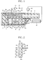
- FIG. 1 shows an aspirator according to a first embodiment.
- the aspirator of FIG. 1 includes a casing 2.
- the casing 2 has a hollow tubular shape and opens at each end. One open end of the casing 2 is closed with an end wall 4.
- a cylinder block 6 is fitted within the casing 2.
- the cylinder block 6 has a bottom at one end thereof, which is in contact with the end wall 4, and an integrally-formed tubular mouthpiece 8 at the other end.
- the mouthpiece 8 projects outward through the other open end of the casing 2.
- the cylinder block 6 has a recess 10 in the outer circumferential surface thereof.
- the recess 10 extends from the bottom of the cylinder block 6 toward the mouthpiece 8.
- the recess 10 defines a heater chamber 12, together with the inner circumferential surface of the casing 2.
- the heater chamber 12 communicates with an internal passage 14 of the mouthpiece 8.
- the cylinder block 6 has further a cylinder bore 16.
- the cylinder bore 16 extends through the cylinder block 6, in the axial direction of the casing 2, parallel to the heater chamber 12.
- the cylinder bore 16 has an open end 16a on the other side, or mouthpiece 8 side of the cylinder block 6.
- the syringe pump 18 includes a hollow outer tube 20.
- the outer tube 20 has a closure wall 22 at one end thereof.
- the closure wall 22 is in contact with the end wall 4 of the casing 2.
- a piston 24 is fitted within the outer tube 20.
- the piston 24 has a piston ring.
- the piston 24 divides the interior of the outer tube 20 into two chambers, of which one is a pump chamber 26 defined between one end face of the piston 24 and the closure wall 22, and the other is a rod chamber.
- the pump chamber 26 communicates with a discharge port 28.
- the discharge port 28 is formed in the closure wall 22.
- the pump chamber 26 is used as a solution chamber, and charged with a solution L in advance.
- the solution L is a medicament, a refreshing/relaxing material or the like which is to be turned into an aerosol.
- the solution L is a refreshing/relaxing material, it can contain constituents of tobacco, for example.
- a screw rod 30 is arranged within the rod chamber of the outer tube 20.
- the screw rod 30 is connected to the piston 24 by a ball joint 32 at one end thereof, and extends coaxially with the outer tube 20.
- the rod chamber of the outer tube 20 is divided by a partition wall 34.
- the partition wall 34 has a threaded hole coaxial with the outer tube 20. The threaded hole extends through the partition wall 34.
- the screw rod 30 extends through the partition wall 34, meshing with the threaded hole.
- the partition wall 34 is formed integrally with the outer tube 20.
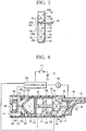
- the screw rod 30 has an end projecting beyond the other end of the outer tube 20, and this projecting end is connected with a rotating cam 36.
- the rotating cam 36 is arranged within the cylinder bore 16, and can rotate integrally with the screw rod 30, allowing axial movement of the screw rod 30.
- the rotating cam 36 and the screw rod 30 are spline-connected.
- the rotating cam 36 has two rows of teeth on its circumferential surface, where the teeth in each rows are distributed all over the circumference of the rotating cam 36 and the two tooth rows are apart from each other in the axial direction of the rotating cam 36.
- One of the two tooth row includes cam teeth 38, while the other includes cam teeth 40.
- the pitch between the adjacent two cam teeth 38 is equal to the pitch between the adjacent two cam teeth 40.
- the position of each cam tooth 38 is half the pitch displaced from the position of each cam tooth 40 in the circumferential direction of the rotating cam 36.
- Each cam tooth 38 is triangular in shape with two sides projecting toward the cam tooth 40. One of these two sides, specifically an upper one of the two sides viewed in FIG. 2 forms a cam face 38a.
- the cam face 38a is inclined relative to the axial direction of the rotating cam 36.
- Each cam tooth 40 is also triangular in shape with two sides projecting toward the cam tooth 38. One of these two sides of the cam tooth 40 forms a cam face 40b.
- the cam face 40b is inclined relative to the axial direction of the rotating cam 36, oppositely to the cam face 38a to be at right angles to the cam face 38a.
- the cam faces 38a and 40b are displaced from each other in the radial direction of the rotating cam 36. More specifically, the cam face 38a is located at the radially outer side of the cam face 40a.
- a proximal end of a push button 42 is slidably fitted in the open end 16a of the cylinder bore 16.
- the push button 42 extends from the cylinder bore 16 outward, beneath the mouthpiece 8.
- a return spring 44 is arranged between the push button 42 and the rotating cam 44.
- the return spring 44 is a compression coil spring.
- the return spring 44 exerts on the push button 42 such force that tends to cause the push button 42 to project through the open end 16a outward, so that the proximal end of the push button 42 is pressed against a stopper ring 46.
- the stopper ring 46 is fixed at the open end 16a.
- the push button 42 has a push rod 48.
- the push rod 48 extends from the push button 42 toward the rotating cam 36.
- a pusher 50 is attached to the distal end of the push rod 48.
- the pusher 50 is triangular in shape with two pusher faces 50a, 50b.
- the pusher faces 50a, 50b are inclined oppositely relative to the axial direction of the rotating cam 36, and able to engage the cam face 38a of the cam tooth 38 and the cam face 40b of the cam tooth 40, respectively.
- the pusher 50 of the pusher rod 48 moves from the position shown in FIG. 2 , passing between two adjacent cam teeth 40, so that the pusher face 50a comes into contact with the cam face 38a of a cam tooth 38 as shown in FIG. 3 and pushes the rotating cam 36 to the left side in FIG. 3 .
- the pusher face 50a and the cam face 38a are both inclined relative to the axial direction of the rotating cam 16, the pusher 50's pushing force produces a component thereof which tends to cause the rotating cam 36 to rotate in one direction. Consequently, the rotating cam 36 rotates about the axis thereof in one direction by a predetermined angle.
- the push button 42 with the push rod 48 returns to the rest position by the force exerted by the return spring 44, so that the pusher face 50b of the pusher 50 comes into contact with the cam face 40b of a posterior one 40 of the aforementioned two cam teeth 40 viewed in the direction of rotation of the rotating cam 36 and pushes this cam face 40b, thereby causing the rotating cam 36 to further rotate about the axis in the same direction by a predetermined angle.
- the push rod 48 then returns to the position shown in FIG. 2 .
- the rotating cam 36 is rotated in the same direction by a predetermined angle. Since the rotating cam 36 is connected with the screw rod 30, the screw rod 30 intermittently rotates with the rotating cam 36. Since the screw rod 30 meshes with the threaded hole in the dividing wall 34, the screw rod 30 advances a predetermined distance toward the piston 24, thereby forcing the piston 24 into the pump chamber 26, each time the screw rod 30 rotates. Consequently, the solution L in the pump chamber 26 is discharged through the discharge port 28 of the syringe pump 18 in a fixed amount each time.
- the casing 2 has an outside air inlet 52 open at its outer surface.
- the outside air inlet 52 is located near the one end of the casing 2.
- the outside air inlet 52 is connected to the internal passage of the mouthpiece 8 by an aerosol generation passage. Next, this generation passage will be described in detail.
- the generation passage includes an introduction passage 56 formed in the end wall 4 of the casing 2.
- the introduction passage 56 has an L shape and extends from the outside air inlet 52 to the heater chamber 12.
- a check valve 54 is inserted in the introduction passage 56.
- the check valve 54 is a reed valve located near the outside air inlet 52, which allows only flow of outside air from the outside air inlet 52 into the introduction passage 56 and blocks air's flowing out of the introduction passage 56 through the outside air inlet 52.
- a tubular heater 58 is located within the heater chamber 12.
- the heater 58 has an internal heating passage 60.
- the heating passage 60 is connected to the introduction passage 56 at one end thereof.
- a joint 62, a connection pipe 64 and a connection ring 66 are disposed in this order, as viewed from the heater 58 side.
- These elements 62 to 66 define a connection passage 68 therein which connects the heating passage 60 and the internal passage 14 of the mouthpiece 14.
- the heating passage 60, the connection passage 68 and the internal passage 14 are linearly arranged.
- connection pipe 64 is placed on a spacer 70 which is located at the bottom of the heater chamber 12.
- the end wall 4 has a joint 4a integrally formed on its inner face and similar in shape to the joint 62.
- the joints 4a and 62 each have a taper end tapering toward the heater 58, and the heater 58 is held between the taper ends of the joints 4a, 62 to be not in contact with the spacer 70.
- an annular space surrounding the heater 58 is provided within the heater chamber 12.
- the introduction passage 56 extends though the joint 4a to communicate with the heating passage 60.
- the joint 4a may be a separate member from the end wall 4.
- the heater 58 is electrically connected to a power source 72 with a switch 74 between.
- the power source 72 is accommodated within the casing 2, while the switch 74 is mounted on the outer surface of the casing 2.
- the heater 58 should desirably be a ceramic heater, it may be made of another chemical- and heat-resistant conductive material such as stainless steel.
- the liquid passage 76 is formed in the end wall 4 of the casing 2 and connected to the discharge port 28 of the syringe pump 18.
- the solution L in the pump chamber 26 is delivered into the liquid passage 76 in a predetermined amount, so that the liquid passage 76 is filled with the solution L.
- the power source 72 supplies power to the heater 58, so that the heater 58 rises to a predetermined temperature. As long as the switch 74 is kept in the "ON” position, the heater 58 is maintained at the predetermined heating temperature.
- the syringe pump 18 operates as described above, so that the solution L in the pump chamber 26 of the syringe pump 18 is delivered to the generation passage, specifically the introduction passage 56, via the liquid passage 76, in a fixed amount.
- the position at which the liquid passage 76 is connected to the introduction passage 56 defines a solution L distributing position A.
- the syringe pump 18 delivers the solution L from the pump chamber 26 to the distributing position A in a fixed amount each time it is activated, and the solution L that has reached the distributing position A plugs the introduction passage 56 at the distributing position A.
- the solution L that has entered the heating passage 60 receives heat from the inner surface of the heater 58 and evaporates quickly.
- the vapor resulting from the solution L quickly condenses and forms an aerosol.
- the aerosol formed is drawn into the user's mouth, through the internal passage 14 of the mouthpiece 8, with the air flow.
- the user can draw the aerosol formed from the solution L into the mouth simultaneously with his/her sucking on the mouthpiece 8.
- the amount of the aerosol generated is determined by the amount of the solution L delivered to the distributing position A, which means that a constant amount of aerosol is generated with each sucking action of the user.
- this aerosol aspirator can generate an aerosol with high responsiveness to the user's sucking action and can ensure the constancy of aerosol generation quantity.
- the push button 42 and the rotating cam 36 may be replaced with a linear or rotating actuator 97.
- the actuator 97 rotates the screw rod 30 of the syringe pump 18 in one direction by a predetermined angle at a time, thereby causing the solution L to be delivered from the syringe pump 18 to the distributing position A in a fixed amount.
- the aspirator according to the first embodiment can be adapted such that the actuator 97 is activated in association with the user's sucking action.
- the aspirator has a sucking sensing sensor 95 in the generation passage or the internal passage 14 of the mouthpiece 8.
- the sucking sensing sensor 8 detects a pressure drop in the generation passage or the internal passage 14, and supplies a detection signal to the actuator 97, thereby activating the actuator 97.
- the push button 42 may be replaced with a linear actuator for rotating the rotating cam 36, and the heater 58 may be replaced with a planar heater.
- the heater chamber 12 forms a part of the generation passage.
- the aspirator according to the first embodiment may include a valve at the downstream end of the liquid passage 76, where the valve is opened in association with activating the syringe pump 18.
- FIG. 4 shows an aerosol aspirator according to a second embodiment.
- the aerosol aspirator according to the second embodiment has a pushbutton mouthpiece 78 at an open end of the casing 2.
- This mouthpiece 78 functions as both the mouthpiece 8 and the push button 4 of the first embodiment.
- the proximal end of the mouthpiece 78 is slidably fitted into the open end of the casing 2.
- a syringe pump 18 has a closure wall 80, which substitutes the closure wall 22 of the first embodiment.
- the closure wall 80 is in the shape of a truncated cone projecting toward the end wall 4 of the casing 2, and has a discharge port 28 at the tip end.
- a porous plug 82 is fitted in the discharge port 28.
- the plug 82 is made of a flexible sponge and projects from the closure wall 80 toward the end wall 4.
- an outer tube 20 of the syringe pump 18 is fitted within the casing 2 and can reciprocate a predetermined distance in the axial direction of the casing 2. More specifically, an annular spring seat 86 is mounted to the inner circumferential surface of the casing 2. The spring seat 86 is located near the closure wall 80 of the outer tube 20. A compression coil spring or return spring 88 is arranged between the spring seat 86 and the closure wall 80. The compression coil spring or the return spring 88 presses the outer tube 20 toward the mouthpiece 78. Here, the compression coil spring or the return spring 88 is sufficiently stronger than the return spring 44 for the mouthpiece 78.
- the spring seat 86 has an end face facing the closure wall 80. An annular stopper 87 is attached to this end face of the spring seat 86. The stopper 87 restricts the movement of the syringe pump 18 toward the end wall 4 of the casing 2.
- the syringe pump 18 divides the interior of the casing 2 into an atomizing chamber 90 adjacent to the end wall 4 and a cam chamber 92 adjacent to the mouthpiece 78.
- the rotating cam 36 as described above is arranged within the cam chamber 92.
- An axial passage 94 is formed in the circumferential wall of the outer tube 20.
- the axial passage 94 extends through the wall of the outer tube 20 to connect the atomizing chamber 90 and the cam chamber 92.
- a flexible tube 84 is arranged within the cam chamber 92. The tube 84 connects the axial passage 94 and the internal passage 14 of the mouthpiece 78.
- the tube 84 has a length enough to allow advancement and withdrawal of the mouthpiece 78 relative to the syringe pump 18 and reciprocation of the syringe pump 18, while maintaining the connection between the axial passage 94 and the internal passage 14.
- An outside air inlet 52 communicates with the atomizing chamber 90.
- the atomizing chamber 90, the axial passage 94 and the tube 84 forms an aerosol generation passage.
- An atomizing plate 96 is located within the atomizing chamber 90.
- the atomizing plate 90 is mounted to the end wall 4 of the casing 2 by a plurality of supports 98.
- the atomizing plate 96 has a flat atomizing surface facing the closure wall 80 of the syringe pump 18. A distributing position A is defined on this atomizing surface.
- the atomizing plate 96 is formed of a planar heater or an ultrasonic vibrator, and the atomizing surface is a heating surface of the heater or a vibrating surface of the ultrasonic vibrator.
- the plug 82 is apart by a predetermined distance from the heater plate 96. This distance is slightly shorter than the distance that the syringe pump 18 moves from the rest position until it hits against the stopper 87.
- the heater plate 96 is electrically connected to a controller 93.
- the controller 93 is connected to the power source 72 with the switch 74 between, and to the sucking sensing sensor 95.
- the controller 93, the power source 72 and the sucking sensing sensor 95 are accommodated within the casing 2.
- a linear actuator 99 is arranged within the cam chamber 92.
- the liner actuator 99 is electrically connected to the controller 93.
- the linear actuator 99 is activated to move the syringe pump 18 from the rest position shown in the drawing toward the heater plate 96.
- the controller 93 supplies power to the heater plate 96, thereby raising the heater plate 96 to a predetermined temperature.
- the push rod 48 and the rotating cam 36 work together in the same way as in the first embodiment to cause a fixed amount of the solution L to be discharged from the syringe pump 18 through the discharge port 28.
- the solution L discharged is absorbed by the plug 82 and held within the plug 82.
- the return spring 44 on the mouthpiece 78 is weaker than the compression coil spring or the return spring 88. Thus, even when the mouthpiece 78 is depressed into the casing 2, the syringe pump 18 stays in the rest position shown in the drawing.
- the sucking sensing sensor 95 supplies a detection signal to the controller 93.
- the controller 93 activates the linear actuator 99. Consequently, the linear actuator 99 forces the syringe pump 18 forward through the partition wall 34, against the force exerted by the compression coil spring or the return spring 88, from the rest position toward the heater plate 96.
- the plug 82 butts the heater plate 96 before the syringe pump 18 hits against the stopper 87.
- the controller 93 deactivates the linear actuator 99. Consequently, the syringe pump 18 is returned to the rest position shown in FIG. 4 by the force exerted by the compression coil spring or the return spring 88, so that the plug 82 separates from the heater plate 96.
- the compression coil spring or the return spring 88, the controller 93 and the linear actuator 99 work together to distribute the solution L from the pump chamber 26 of the syringe pump 18 to the distributing position A in a fixed amount in each stroke.
- the heater plate Before the solution L is distributed to the position A, the heater plate has been raised to the predetermine temperature. Thus, when the solution L is distributed onto the heater plate 96, the solution evaporates quickly. Then, upon contacting the air flow in the atomizing chamber 90, the vapor resulting from the solution L is atomized, namely turns into an aerosol. Thus, the user can suck a fixed amount of aerosol together with air immediately after starting the sucking action. In other words, also the aerosol aspirator according to the second embodiment ensures the constancy of aerosol sucking quantity and high responsiveness.
- the aerosol aspirator uses, as the atomizing plate, an ultrasonic vibrating plate 96 in place of the heater plate, the ultrasonic vibrating plate 96 can turn the solution L into an aerosol directly, namely without evaporating it.
- Such ultrasonic vibrating plate 96 is particularly suited for turning into an aerosol a solution that varies in qualities under rapid heating.
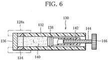
- FIG. 5 shows an aerosol aspirator according to a third embodiment.
- the aerosol aspirator of FIG. 5 includes a casing 102 made of synthetic resin.
- the casing 102 comprises, for example three casing parts, i.e., an upper casing part 102a, an intermediate casing part 102b and a lower casing part 102c.
- a hollow mouthpiece 104 extends through a rear wall of the upper casing part 102a backward, namely to the right side in FIG. 5 .
- This mouthpiece 104 is detachably attached to the upper casing part 102b.
- a support ring 106 is arranged within the upper casing part 102a to be located adjacent to the rear wall.
- the mouthpiece 104 extends through the rear wall of the upper casing part 102a, with its inner end removably fitted into the support ring 106.
- the upper casing part 2a has an outside air inlet 111 open at the upper surface, near the front end thereof.
- the outside air inlet 111 is connected to the inner end of the mouthpiece 104 by an aerosol generation passage 110.
- the aerosol generation passage 110 extends within the upper casing part 102a. More specifically, in the third embodiment, a T-tube 112, a heater holder 114, a heater 116 and a heater holder 118, disposed in this order from the left side in FIG. 5 , form the generation passage 110.
- the heater holder 114, the heater 116 and the heater holder 118 are tubular in shape and disposed coaxially with the mouthpiece 104.
- the heater holders 114, 118 have heat-resistant property.
- the T-tube 112 has first and second ends coaxial with the mouthpiece 104 and a third end connected to the outside air inlet 111.
- the first end of the T-tube 112 is connected to the heater holder 116, and the second end of the T-tube 112 is closed.
- the internal passages of the heater holder 114, the heater 116 and the heater holder 118 are approximately equal in cross-sectional area to the internal passage of the mouthpiece 104.
- a reed-valve type check valve (not shown) may be provided at the outside air inlet 111 to allow only an air flow from the outside air inlet 111 into the generation passage 110.
- the heater holders 114, 118 hold the heater 116 in a manner pinching the heater 116 between them.
- the heater holder 114 is arranged within the upper casing part 102a by means of the support ring 120, while the heater holder 118 is inserted in the aforementioned support ring 106, thereby connected to the mouthpiece 104.
- the heater 116 is a ceramic heater, it may be made of another chemical- and heat-resistant conductive material such as stainless steel.
- the upper casing part 102a should include a lid (not shown) that can be opened and closed to allow the heater 116 to be removed from the upper casing part 102a.
- the intermediate casing part 102b defines a rear chamber 122 and a front chamber 124 therein, where the rear chamber 122 and the front chamber 124 are separated by a partition wall.
- the rear chamber 122 extends between the aforementioned support rings 120 and 106.
- a support block 126 is arranged, and a syringe holder 128 is mounted on the support block 126.
- the syringe holder 128 is rectangular in cross section and extends parallel to the aforementioned generation passage 110.
- the syringe holder 128 has a stepped cylinder bore defined therein. The cylinder bore is open at each end of the syringe holder 128.
- a cartridge type syringe pump 130 is removably inserted in the syringe holder 128.
- a stopper sleeve 128a is fitted within the syringe holder 128, at its front end thereof as viewed in the direction of inserting the syringe pump 130.
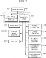
- FIG. 6 shows the syringe pump 130 in detail.
- the syringe pump 130 includes an outer cylinder 132.
- a circular septum 136 is mounted on the front end of the cylinder 132 by means of an annular holder 134.
- a piston 138 is fitted into the cylinder 132. The piston 138 is allowed to slide in the cylinder 132 but prevented from rotating about the axis thereof.
- a pump chamber 140 is defined in the cylinder 132, between the piston 138 and the septum 136.
- the pump chamber 140 is filled with a solution L of a type mentioned above.
- the piston 138 has a hollow drive rack 142.
- the drive rack 142 extends from the piston 138 toward the rear end of the outer cylinder 132, coaxially with the piston 138.
- the drive rack 142 has an end wall at the rear end thereof.
- the end wall is formed as a nut, or in other words, the end wall of the drive rack 142 has a threaded hole, through which a screw rod 144 is screwed into the drive rack 142.
- the screw rod 144 meshes with the threaded hole, with a front end located within the drive rack 142 and a rear end outside the drive rack 142.
- a gear 146 is mounted on the rear end of the screw rod 144. As shown in FIG. 5 , when the syringe pump 130 is set within the syringe holder 128, the gear 146 meshes with a reduction gear 148 meshing with a drive gear 150.
- the drive gear 150 is connected to a motor 152 as a drive source.
- the motor 152 can rotate normally and reversely and is mounted on the aforementioned support block 126.
- the motor 142 may be any of a step motor, a direct-current motor and a servomotor.
- the reduction gear 148 is rotatably supported within the rear chamber 122.
- a hollow needle 154 is inserted into the pump chamber 140 of the syringe pump 130, through the septum 136.
- the needle 154 is supported by a disc-shaped needle holder 156.
- the needle holder 156 is located within the rear chamber 122.
- the needle 154 is connected to a liquid passage 158, and the liquid passage 158 is connected to the aforementioned generation passage 110.
- the liquid passage 158 includes an internal passage extending in the heater holder 114, the support ring 120 and the upper and intermediate casing parts 102a, 102b, and a connection pipe extending within the rear chamber to connect the internal passage and the needle 154.
- the internal passage has an open end at a distributing position A defined on the inner surface of the heater holder 14.
- a lid (not shown) allowed to be opened and closed is provided at the back wall of the intermediate casing part 102b. With the lid opened, insertion of the syringe pump 130 into the syringe holder 128 and removal of the syringe pump 130 from the syringe holder 128 are possible.
- a control device 160 is accommodated in the front chamber 124, and an electric cell 162 is accommodated in the aforementioned lower casing part 102c.
- an electric cell 162 is accommodated in the aforementioned lower casing part 102c.
- a primary cell such as a fuel cell or a nickel-hydrogen cell, or a secondary cell such as a nickel-cadmium cell, a nickel-hydrogen cell or a lithium cell can be used.
- the electrical cell 162 is a lithium cell.
- the lower casing part 102c has an openable and closable lid (not shown), and with the lid opened, the cell 162 can be replaced.
- the electrical cell 162 becomes electrically connected to the control device 160 via a connector 164, to serves as a power source for not only the control device 160 but also the aforementioned heater 116 and motor 152.
- control device 160 includes a voltage stabilization circuit 166 and a control unit 168, and the control unit 168 includes a microprocessor, memory, a peripheral, an input-output interface, etc., for example.
- the indicator 170 is, for example attached to the upper surface of the upper casing part 102a, near the mouthpiece 104.
- a power source switch 172 manually operated to allow or shut off the supply of power from the electrical cell 162
- a liquid supply switch 174 to allow manual operation of the syringe pump 130
- a sucking sensing sensor 176 to sense the user's sucking on the mouthpiece 104 that draws air in the generation passage to the mouthpiece
- a cartridge sensing sensor 178 to sense insertion of the syringe pump 130 in the syringe holder 128, a temperature sensor 180 to detect temperature of the heater 116, etc.
- the power source switch 172 and the liquid supply switch 174 are disposed at the front wall as shown in FIG. 5 , or a side wall.
- the sucking sensing sensor 176 is a pressure sensor disposed between the aforementioned heater holder 118 and the mouthpiece 104 to detect pressure in the generation passage 110.
- a flow sensor to detect air flow in the generation passage 110 may be used in place of the pressure sensor.
- the aforementioned T-tube 112 has the second end open at the outer surface of the upper casing part 102a, and the flow sensor is disposed at this open second end.
- the cartridge sensing sensor 178 is, for example a limit switch and disposed on the stopper sleeve 128a of the syringe holder 128.
- the cartridge sensing sensor 178 is activated by the syringe pump 130 that has been inserted in the syringe holder 128.
- the temperature sensor 180 is attached to the heater 116.
- a thermistor, a thermocouple or a platinum resistance wire can be used as the temperature sensor 180.
- control unit 168 may function as the temperature sensor 180. Specifically, the control unit 168 may estimate the temperature of the heater 116 from the power supplied to the heater 116.
- the control unit 168 receives signals from the switches and sensors connected to its input, and controls heating of the heater 116 and operation of the syringe pump 130 on the basis of those signals.
- the control unit 168 further detects the operating state of at least one of the heater 116, the syringe pump 130 and the cell 162, and causes the indicator 170 to present the detection result.
- the indicator 170 will be described later.
- preprocessing performed subsequent to insertion of the syringe pump 130 into the syringe holder 128, and postprocessing performed prior to replacement of the syringe pump 130 will be described.
- the aforementioned cartridge sensing sensor 178 senses the insertion of the syringe pump 130 and supplies a sensing signal to the control unit 178, thereby causing the control unit 168 to perform preprocessing.
- control unit 168 drives the motor 152 for the syringe pump 130 to rotate in one direction, thereby causing the gear 146 to rotate by a predetermined angle. Consequently, the piston 138 of the syringe pump 130 advances a predetermined distance in the direction causing a reduction in volume of the pump chamber 140, namely toward the septum 138, thereby discharging the solution L from the pump chamber 140 of the syringe pump 130 into the liquid passage 158. The amount of the solution L discharged at this time corresponds to the volume of the liquid passage 158, so that the liquid passage 15 is filled with the solution L. With this, the preprocessing is completed.
- the control unit 168 drives the motor 152 for the syringe pump 130 to rotate in the reverse direction, thereby causing the piston to withdraw.
- Such withdrawal of the piston 138 creates a negative pressure in the pump chamber 140. Consequently, the aforementioned solution L filling the liquid passage 158 is all drawn back into the pump chamber 140, with which the postprocessing is completed.
- the liquid passage 158 becomes empty.
- the syringe pump 130 is replaced with a new syringe pump holding a solution different from the solution L, mixing of the different solutions does not occur in the liquid passage 158.
- the control unit 168 Prior to sucking on the mouthpiece 104, the user first puts the liquid supply switch 174 in an "ON" position. Upon receiving an "ON" signal from the liquid supply switch 174, the control unit 168 causes the piston 138 of the syringe pump 130 to advance a predetermined distance. Consequently, a fixed amount of the solution L is delivered from the pump chamber 140 of the syringe pump 130 to the distributing position A in the generation passage 110, and the solution L delivered plugs the generation passage 110 at the distributing position A.
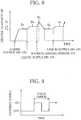
- the control unit 168 can control the temperature of the heater 116, for example in a temperature control process shown in FIG, 8 . Next, this temperature control process will be described.
- the control unit 168 Upon the user's putting the power switch 172 in the "ON" position, the control unit 168 starts supply of power to the heater 16. While monitoring the heater 116 temperature on the basis of a detection signal from the temperature sensor 180, the control unit 168 quickly raises the heater 116 to a predetermined early preheating temperature Ta (150°C, for example) and maintains the heater at this early preheating temperature Ta (first stage of a preheating mode).
- a predetermined early preheating temperature Ta 150°C, for example
- the control unit 168 drives the motor 152 for the syringe pump 130, thereby causing the piston 138 of the syringe pump 130 to advance a predetermined distance. Consequently, a fixed amount of the solution L is delivered to the distributing position A in the generation passage 110 from the pump chamber 140 of the syringe pump 130 via the liquid passage 158, and as mentioned above, the solution L delivered closes the generation passage 110 at the distributing position A.
- control unit 168 raises the heater 116 to a late preheating temperature Tb (185°C, for example) higher than the early preheating temperature Ta, on the basis of a detection signal from the temperature sensor 180, and maintains the heater at this late preheating temperature Tb (second stage of the preheating mode).
- Tb 185°C, for example
- the control unit 168 quickly raises the heater 116 from the late preheating temperature Tb to an evaporating heating temperature Tc (220°C, for example), on the basis of a detection signal from the temperature sensor 180 (evaporating heating mode).
- the evaporating heating temperature Tc is a temperature of the heater 116 enough to atomize the solution L, namely turn it into an aerosol.
- the solution L is transferred from the distributing position A toward the heater 116, simultaneously with which, the heater 116 is raised to the evaporating heating temperature Tc. Consequently, all the solution that has entered the heater 116 is atomized, namely turns into an aerosol, under heat from the heater 116, and the aerosol formed is drawn into the user's mouth through the mouthpiece 104 together with the air flow.
- control unit 168 stops supply of power to the heater 116.
- control unit 168 resumes supply of power to the heater 116 to maintain the heater 116 at the early preheating temperature Ta until the liquid supply switch 174 is put in the "ON" position next time (first stage of the preheating mode).
- the control unit 168 repeats the above-described temperature control.
- the above mentioned temperature control of the heater 116 is carried out by pulse-width modulation.
- duty cycle namely the ratio of pulse "ON" time in which current is supplied to the heater 116 to pulse period is modulated.
- the duty ratio D0 for the period from the time that the power switch 172 is put in the "ON" position until the heater 116 is raised to the early preheating temperature Ta is determined to be a maximum allowable for the electrical cell 162.
- the duty ratios D1, D2 for maintaining the heater 116 at the early and late preheating temperatures Ta, Tb, respectively, are each determined to be a minimum required for that.
- the duty ratio D3 for raising the heater 116 from the late preheating temperature Tb to the evaporating heating temperature Tc is determined to be a maximum that does not cause a change in composition of the solution L. Such maximum value depends on the composition of the solution L.
- the duty ratio D4 for raising the heater 116 from the early preheating temperature Ta to the late preheating temperature Tb may be determined to be equal to the duty ratio D3, for example.
- the heater 116 is raised to the late preheating temperature Tb before the user does sucking action. This reduces considerably the period of time between the user's starting sucking action and the heater 116 reaching the evaporating heating temperature Tc, and therefore allows the solution L to form an aerosol in the air drawn by user simultaneously with the user's sucking action, thereby preventing the user from feeling uncomfortable due to a time lag before generation of the aerosol.
- the heater 116 is maintained at the early preheating temperature Ta lower than the evaporating heating temperature Tc, and it is after the liquid supply switch 174 is put in the "ON" position that the heater 116 is raised from the early preheating temperature Ta to the late preheating temperature Tb. This reduces the consumption of the electrical cell 162, namely prolongs the life of the cell 162.
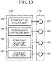
- the control unit 168 includes a temperature evaluation section 182 as shown in FIG. 10 .
- the temperature evaluation section 182 determines whether or not the heater 116 has reached the late preheating temperature Tb, from a detection signal from the temperature sensor 180. If the result of determination is "true", the temperature evaluation section 182 causes the indicator 170 to indicate that the aspirator is "ready for sucking".
- the indicator 170 includes an indication lamp 184, so that the user can start sucking action after confirming that the indication lamp 184 is on. At the time that the user has started sucking action, the indication lamp 184 is turned off.
- the control unit 168 further include an inhabitation determination section 186.
- the inhabitation determination section 186 keeps the liquid supply switch 174 unenable until the user starts sucking action, i.e., a sensing signal is emitted from the sucking sensing sensor 176 after the syringe pump 130 is activated.
- the syringe pump 130 is not double-activated. This ensures that the amount of the solution L delivered to the distributing position A in the generation passage 110 is determined by a single action of the syringe pump 130.
- the indicator 170 may include an indication lamp 188 to indicate that activation of the syringe 170 is inhibited.
- the inhabitation determination section 186 turns on the indication lamp 188 simultaneously with inhibiting activation of the syringe 170 to tell the user that double activation of the syringe pump 130, thus double delivery of the solution L is inhibited.
- the control unit 138 may further include a remaining quantity detection section 190 for detecting the amount of the solution L remaining in the syringe pump 130 and a voltage detection section 192 for detecting the voltage of the electrical cell 162, and the indicator 170 may include indication lamps 194, 196 corresponding to the remaining quantity detection section 190 and the voltage detection section 192, respectively.
- the remaining quantity detection section 190 estimates the amount of the solution L remaining in the syringe pump 130 from the amount of the solution discharged from the syringe pump 130 in the aforementioned preprocessing, and at least either the number of times that the syringe pump 130 has been activated or the number of times that the sensing signal has been emitted from the sucking sensor 176.
- the remaining quantity detection section 190 turns on the indication lamp 194 of the indicator 170 to tell the user that the remaining solution L is "scarce".
- the voltage detection section 192 detects the output voltage of the electrical cell 162, and when the output voltage decreases to a predetermined value or below, turns on the indication lamp 196 of the indicator 170 to tell the user that "the remaining cell charge is scarce".
- Indicating the states of the aspirator, specifically of the heater 116, syringe pump 130 and electrical cell 162 by the ON/OFF of the indication lamps 184, 188, 194 and 196 can help the user's appropriate use of the aspirator to suck an aerosol, and urge the preparation of a new syringe pump or electrical cell to replace the syringe pump 130 and or electrical cell 162.
- the heater 166 is removably set within the upper casing part 102a. This allows the user to remove the heater 116 and easily clean the generation passage 110 as well as the inside of the heater 116.
- the indicator 170 may include a liquid crystal display in place of the indication lamps, for example. In this case, the above-mentioned various states are presented on the liquid crystal display.
- the liquid supply switch 174 is not indispensable. When the aspirator does not include the liquid supply switch 174, the control unit 168 controls the temperature of the heater 116 in a temperature control process, as shown in FIG. 11 or 12 .
- the control unit 168 raises the heater 116 to a preheating temperature Td lower than an evaporating heating temperature Tc and maintains it at this preheating temperature Td (preheating mode). Then the user starts sucking action, and when the sucking sensing sensor 176 emits a sensing signal, the control unit 168 raises the heater 116 to the evaporating heating temperature Tc (evaporating heating mode) and stops the supply of current to the heater 116.
- the control unit 168 resumes the supply of current to the heater 116 to raise the heater 116 back to the preheating temperature Td.
- the control unit 168 may activate the syringe pump 130 to deliver a fixed amount of the solution L to the distributing position A in the generation passage 110, while the heater 116 is rising to the evaporating heating temperature Tc.
- the control unit 168 activates the syringe pump 130 to deliver the solution L, while the heater 116 is rising from the preheating temperature Td to the atomizing temperature Tc.
- the control unit 168 activates the syringe pump 130 to deliver the solution L, while the heater 116 is rising from the preheating temperature Td to the atomizing temperature Tc.
- air in the generation passage 110 has already been drawn toward the mouthpiece by the user's sucking on the mouthpiece 104, so that the solution L delivered to the distributing position A is immediately transferred into the heater 116, heated by the heater 116 and atomized, namely forms an aerosol with air sucked.
- the solution L may be delivered while the heater 116 is maintained at the preheating temperature Td. Only the first delivery of the solution L may be carried out at the time that the power switch 172 is put in the "ON" position.
- the preheating temperature Td may be equal to the aforementioned late preheating temperature Tb.
- the preheating temperature Td and the early preheating temperature Ta are so determined that the time taken for the heater 116 to reach the evaporating heating temperature Tc after the user's starting sucking action, thus, the time taken for generation of an aerosol may not cause the user to feel uncomfortable, and that preheating may not cause a change in composition of the solution L.
- the control unit 168 performs a termination mode.
- the termination mode includes reverse operation of the syringe pump 130, thereby bringing the solution L back to the delivery portion or the pump chamber 140.
- Such termination mode is performed also in the temperature control process shown in FIG. 8 using of the liquid supply switch 174.
- the control unit 168 can adopt the temperature control process as shown in FIG. 12 .
- the control unit 168 activates the syringe pump 130 upon receiving a sensing signal from the sucking sensing sensor 176. Since the delivery of the solution L is caused following the user's sucking action, the possibility that the solution L remains at the distributing position A in the generation passage 110 is eliminated.
- the control unit 168 does not start or stop functioning unless the power switch stays in the "ON” or “OFF” position for a predetermined period of time. It is however desirable that the supply of current to the heater 116 be started at the same time as the power switch 172 is put in the "ON" position.
- control unit 168 makes ineffective the power switch 172 in the "ON" position, if the syringe pump 130 is not attached, or in other words, a sensing signal is not emitted from the cartridge sensing sensor 178.
- control unit 168 has a function of storing usage history such as how many times the user has done suction action, how long power is supplied to the heater 116, how many times the syringe pump 130 has been replaced, etc.
- the aerosol aspirator includes a reading section to read information on the syringe pump 130 at the time that the syringe pump 130 is attached, if the syringe pump 130 has information such as the type and volume of solution in the form of a bar code or the like.
- the control unit 168 changes the temperature control process for the heater 116, depending on the solution type identified from the information read by the reading section 168.
- An identity verification system based on fingerprint, an IC tag, an IC card or the like may be incorporated into the aerosol aspirator to reliably prevent unauthorized use of the aerosol aspirator. Further, the power source of the aerosol aspirator does not need to be accommodated within the casing.
- aerosol aspirator according to the embodiments described above all use a syringe pump to supply a solution
- another type of fixed displacement pump such as a gear pump, can be used.
Claims (15)
- Aspirateur d'aérosol, comprenant :un boîtier (2) avec un embout (8), ledit boîtier (2) comportant une entrée d'air extérieur (52) ouverte au niveau d'une surface extérieure de celui-ci,un dispositif de génération disposé à l'intérieur dudit boîtier (2) pour générer un aérosol, ledit dispositif de génération comportantun passage de génération d'aérosol (56, 60, 62, 68) s'étendant de l'entrée d'air extérieur (52) à l'embout (8),une pompe d'alimentation (18) ayant une chambre de solution (26) contenant une solution (L) devant être transformée en un aérosol, pour délivrer la solution (L) depuis la chambre de solution (26) audit passage de génération d'aérosol dans une quantité fixe chaque fois que la pompe d'alimentation (18) est activée, etun dispositif de chauffage (58) pour évaporer la solution (L) délivrée depuis la chambre de solution (26) pour générer l'aérosol,caractérisé en ce quele passage de génération d'aérosol (56, 60, 62, 68) a une position de distribution (A) définie comme un orifice ouvrant une surface intérieure dudit passage de génération d'aérosol de telle sorte que la solution (L) délivrée depuis la chambre de solution (26) est introduite dans le passage de génération d'aérosol (56, 60, 62, 68) par l'orifice,le dispositif de chauffage (58) est situé en aval de la position de distribution (A) dans le passage de génération d'aérosol (56, 60, 62, 68), le dispositif de chauffage (58) évaporant la solution (L) qui est déplacée jusqu'au dispositif de chauffage (58) depuis la position de distribution (A) quand un utilisateur aspire l'air dans le passage de génération d'aérosol (56, 60, 62, 68) par l'embout (8), etune distance entre la position de distribution (A) et le dispositif de chauffage est déterminée pour empêcher l'évaporation de la solution (L) à la position de distribution (A) par la chaleur transférée depuis le dispositif de chauffage (58).
- Aspirateur d'aérosol selon la revendication 1, dans lequel le passage de génération d'aérosol est un passage tubulaire.
- Aspirateur d'aérosol selon la revendication 1, dans lequel le dispositif de chauffage (58) est de forme tubulaire et forme une partie du passage de génération.
- Aspirateur d'aérosol selon la revendication 3, dans lequel la pompe d'alimentation (18) est une pompe à seringue (18), et
ledit dispositif de génération comporte en outre un passage de liquide (76) reliant la pompe à seringue (18) et le passage de génération à la position de distribution (A) de telle sorte que le passage de génération est fermé avec la solution délivrée depuis la pompe à seringue (18) à la position de distribution (A). - Aspirateur d'aérosol selon la revendication 4, comprenant en outre un commutateur d'alimentation (74) pour activer le dispositif de chauffage (58) avant d'activer la pompe à seringue (18).
- Aspirateur d'aérosol selon la revendication 5, dans lequel ledit dispositif de génération comporte en outre un bouton-poussoir (42) actionné manuellement pour activer la pompe à seringue (18).
- Aspirateur d'aérosol selon la revendication 5, dans lequel ledit dispositif de génération comporte en outre un actionneur (97) pour activer la pompe à seringue (18), et un capteur de détection d'aspiration (95) pour détecter l'aspiration d'air dans le passage de génération au moyen de l'embout (8) et activer l'actionneur (97).
- Aspirateur d'aérosol selon la revendication 5, dans lequel
l'aspirateur comprend en outre un dispositif de contrôle (168) pour contrôler le fonctionnement de la pompe d'alimentation (130) et du dispositif de chauffage (116) de telle sorte que, quand l'air dans le passage de génération est aspiré au moyen de l'embout (8), un aérosol obtenu par évaporation de la solution (L) est produit dans l'air aspiré. - Aspirateur d'aérosol selon la revendication 8, dans lequel ledit dispositif de contrôle (168) comporte un capteur de détection d'aspiration (176) pour détecter l'aspiration d'air et émettre un signal de détection.
- Aspirateur d'aérosol selon la revendication 8, dans lequel ledit dispositif de contrôle (168) comporte un processus de régulation de température pour activer le dispositif de chauffage quand le commutateur d'alimentation (172) est placé dans une position « MARCHE », et
ledit processus de régulation de température a un mode de préchauffage pour maintenir le dispositif de chauffage (58) à une température de préchauffage prédéterminée (Tb) et un mode de chauffage d'évaporation pour élever le dispositif de chauffage (58) jusqu'à une température de chauffage d'évaporation (Tc) supérieure à la température de préchauffage (Tb), nécessaire pour évaporer la solution (L), le mode de chauffage d'évaporation étant initié quand le signal de détection est émis. - Aspirateur d'aérosol selon la revendication 10, dans lequel ledit dispositif de contrôle (168) comporte en outre un commutateur d'alimentation en liquide (174) actionné manuellement pour activer le dispositif de chauffage (116), et
le mode de préchauffage comporte une première phase de chauffage du dispositif de chauffage (116) jusqu'à une température (Ta) inférieure à la température de préchauffage (Tb) et de maintien de celui-ci à cette température inférieure (Ta) jusqu'à ce que le commutateur d'alimentation en liquide (174) soit placé dans une position « MARCHE », et une deuxième phase de chauffage du dispositif de chauffage (116) jusqu'à la température de préchauffage (Tb) et de maintien de celui-ci à la température de préchauffage (Tb) après que le commutateur d'alimentation en liquide (174) a été placé dans la position « MARCHE ». - Aspirateur d'aérosol selon la revendication 10 ou 11, dans lequel ledit dispositif de contrôle (168) comporte en outre un capteur de température (180) pour détecter la température du dispositif de chauffage (116) et émettre un signal de détection, et un moyen d'évaluation de température pour amener un indicateur (170) à indiquer que l'aspirateur est « prêt à aspirer » lorsqu'il est déterminé que le dispositif de chauffage (116) a atteint la température de préchauffage (Tb), en fonction du signal de détection provenant du capteur de température (180).
- Aspirateur d'aérosol selon la revendication 10, dans lequel ledit dispositif de contrôle (168) active la pompe d'alimentation (130) pendant que le dispositif de chauffage (116) est élevé vers la température de chauffage d'évaporation.
- Aspirateur d'aérosol selon la revendication 13, dans lequel ledit dispositif de contrôle (168) active la pompe d'alimentation (130) quand le capteur de détection d'aspiration (176) émet un signal de détection.
- Aspirateur d'aérosol selon la revendication 13, dans lequel ledit dispositif de contrôle (168) comporte un moyen d'inhibition (186) pour inhiber l'activation suivante de la pompe d'alimentation (130) jusqu'à ce que le capteur de détection d'aspiration (176) émette un signal de détection après que la pompe d'alimentation (130) a été activée.
Priority Applications (1)
| Application Number | Priority Date | Filing Date | Title |
|---|---|---|---|
| PL07791045T PL2047880T3 (pl) | 2006-08-01 | 2007-07-20 | Urządzenie do zasysania aerozolu oraz sposób zasysania aerozolu |
Applications Claiming Priority (3)
| Application Number | Priority Date | Filing Date | Title |
|---|---|---|---|
| JP2006209700 | 2006-08-01 | ||
| JP2007157501 | 2007-06-14 | ||
| PCT/JP2007/064307 WO2008015918A1 (fr) | 2006-08-01 | 2007-07-20 | Dispositif d'aspiration d'aérosol et son procédé d'aspiration |
Publications (3)
| Publication Number | Publication Date |
|---|---|
| EP2047880A1 EP2047880A1 (fr) | 2009-04-15 |
| EP2047880A4 EP2047880A4 (fr) | 2014-10-29 |
| EP2047880B1 true EP2047880B1 (fr) | 2017-08-30 |
Family
ID=38997098
Family Applications (1)
| Application Number | Title | Priority Date | Filing Date |
|---|---|---|---|
| EP07791045.3A Revoked EP2047880B1 (fr) | 2006-08-01 | 2007-07-20 | Dispositif d'aspiration d'aérosol et son procédé d'aspiration |
Country Status (12)
| Country | Link |
|---|---|
| US (1) | US9067029B2 (fr) |
| EP (1) | EP2047880B1 (fr) |
| JP (1) | JP5041550B2 (fr) |
| KR (1) | KR101076144B1 (fr) |
| CN (1) | CN101522244B (fr) |
| CA (1) | CA2659083C (fr) |
| HK (1) | HK1131573A1 (fr) |
| MY (1) | MY147399A (fr) |
| PL (1) | PL2047880T3 (fr) |
| RU (1) | RU2411047C2 (fr) |
| TW (1) | TWI337554B (fr) |
| WO (1) | WO2008015918A1 (fr) |
Cited By (1)
| Publication number | Priority date | Publication date | Assignee | Title |
|---|---|---|---|---|
| WO2021003438A1 (fr) * | 2019-07-03 | 2021-01-07 | Airja, Inc. | Dispositifs de distribution d'aérosol et leurs procédés d'utilisation |
Families Citing this family (128)
| Publication number | Priority date | Publication date | Assignee | Title |
|---|---|---|---|---|
| US20160345631A1 (en) | 2005-07-19 | 2016-12-01 | James Monsees | Portable devices for generating an inhalable vapor |
| US9675109B2 (en) * | 2005-07-19 | 2017-06-13 | J. T. International Sa | Method and system for vaporization of a substance |
| US11647783B2 (en) | 2005-07-19 | 2023-05-16 | Juul Labs, Inc. | Devices for vaporization of a substance |
| US8991402B2 (en) | 2007-12-18 | 2015-03-31 | Pax Labs, Inc. | Aerosol devices and methods for inhaling a substance and uses thereof |
| CN101537221A (zh) * | 2008-03-06 | 2009-09-23 | 雷斯梅德有限公司 | 呼吸气体的湿化 |
| EP2113178A1 (fr) | 2008-04-30 | 2009-11-04 | Philip Morris Products S.A. | Système de fumée chauffé électriquement avec une portion de stockage liquide |
| AT507187B1 (de) * | 2008-10-23 | 2010-03-15 | Helmut Dr Buchberger | Inhalator |
| US9999722B2 (en) * | 2008-12-31 | 2018-06-19 | Roche Diabetes Care, Inc. | Portable medical fluid delivery device with drive screw articulated with reservoir plunger |
| ES2632352T3 (es) * | 2009-11-11 | 2017-09-12 | Koninklijke Philips N.V. | Dispositivo y método de entrega de medicamentos |
| WO2011121698A1 (fr) * | 2010-03-29 | 2011-10-06 | 日本たばこ産業株式会社 | Réservoir de liquide pour un aspirateur d'aérosol |
| US20140158129A1 (en) | 2010-09-22 | 2014-06-12 | Clovershield, Inc. | Transversely-activated valve for a therapeutic vaporizer bag attachment system |
| US20130174842A1 (en) | 2010-09-22 | 2013-07-11 | Clovershield, Inc. | Therapeutic vaporizer |
| US11577035B2 (en) | 2010-09-22 | 2023-02-14 | Robert Irving Pratt, JR. | Therapeutic vaporizer |
| EP2454956A1 (fr) * | 2010-11-19 | 2012-05-23 | Philip Morris Products S.A. | Système de fumage chauffé électriquement comportant au moins deux unités |
| EP2460423A1 (fr) * | 2010-12-03 | 2012-06-06 | Philip Morris Products S.A. | Système générateur d'aérosol à chauffage électrique avec une commande du chauffage améliorée |
| EP2468116A1 (fr) | 2010-12-24 | 2012-06-27 | Philip Morris Products S.A. | Système de génération d'aérosol disposant de supports pour gérer la consommation d'un substrat liquide |
| EP2468117A1 (fr) * | 2010-12-24 | 2012-06-27 | Philip Morris Products S.A. | Système de génération d'aérosol disposant de supports pour déterminer la déplétion d'un substrat liquide |
| CN103415222B (zh) * | 2011-02-09 | 2016-12-07 | Sis资源有限公司 | 可变电力控制电子香烟 |
| JP2012217500A (ja) * | 2011-04-05 | 2012-11-12 | Morita Mfg Co Ltd | 耳鼻咽喉科用噴霧装置 |
| CA2829043C (fr) * | 2011-04-22 | 2019-09-03 | Chong Corporation | Systeme d'administration de medicament |
| US8528569B1 (en) | 2011-06-28 | 2013-09-10 | Kyle D. Newton | Electronic cigarette with liquid reservoir |
| EA202190195A1 (ru) * | 2011-08-16 | 2021-07-30 | Джуул Лэбз, Инк. | Низкотемпературное электронное устройство испарения |
| KR101540192B1 (ko) | 2011-08-19 | 2015-07-28 | 니뽄 다바코 산교 가부시키가이샤 | 에어로졸 흡인기 |
| EP2609820A1 (fr) * | 2011-12-30 | 2013-07-03 | Philip Morris Products S.A. | Détection d'un substrat formant un aérosol dans un dispositif de génération d'aérosol |
| MY168133A (en) | 2011-12-30 | 2018-10-11 | Philip Morris Products Sa | Aerosol-generating device with air flow detection |
| ES2655904T3 (es) * | 2012-01-27 | 2018-02-22 | Sulzer Metco (Us) Inc. | Enfriamiento de bucle cerrado de una pistola de plasma para mejorar la vida del hardware |
| US11517042B2 (en) | 2012-04-25 | 2022-12-06 | Altria Client Services Llc | Digital marketing applications for electronic cigarette users |
| CN104640708B (zh) * | 2012-05-15 | 2017-11-07 | 艾诺维亚股份有限公司 | 喷射器设备、方法、驱动器及用于其的电路 |
| US9814262B2 (en) | 2012-07-11 | 2017-11-14 | Sis Resources, Ltd. | Hot-wire control for an electronic cigarette |
| US10517530B2 (en) | 2012-08-28 | 2019-12-31 | Juul Labs, Inc. | Methods and devices for delivering and monitoring of tobacco, nicotine, or other substances |
| US8881737B2 (en) | 2012-09-04 | 2014-11-11 | R.J. Reynolds Tobacco Company | Electronic smoking article comprising one or more microheaters |
| HUE032696T2 (en) | 2012-09-11 | 2017-10-30 | Philip Morris Products Sa | Device and method for controlling electric heating element, limiting temperature |
| CN103404969A (zh) * | 2012-10-05 | 2013-11-27 | 佛山市新芯微电子有限公司 | 电子烟装置 |
| GB2507104A (en) | 2012-10-19 | 2014-04-23 | Nicoventures Holdings Ltd | Electronic inhalation device |
| GB2507102B (en) * | 2012-10-19 | 2015-12-30 | Nicoventures Holdings Ltd | Electronic inhalation device |
| US10034988B2 (en) | 2012-11-28 | 2018-07-31 | Fontem Holdings I B.V. | Methods and devices for compound delivery |
| TWI608805B (zh) | 2012-12-28 | 2017-12-21 | 菲利浦莫里斯製品股份有限公司 | 加熱型氣溶膠產生裝置及用於產生具有一致性質的氣溶膠之方法 |
| USD752807S1 (en) | 2013-02-19 | 2016-03-29 | 1Ready, Llc | Therapeutic vaporizer |
| US10279934B2 (en) | 2013-03-15 | 2019-05-07 | Juul Labs, Inc. | Fillable vaporizer cartridge and method of filling |
| US10638792B2 (en) | 2013-03-15 | 2020-05-05 | Juul Labs, Inc. | Securely attaching cartridges for vaporizer devices |
| US10653180B2 (en) | 2013-06-14 | 2020-05-19 | Juul Labs, Inc. | Multiple heating elements with separate vaporizable materials in an electric vaporization device |
| CN105263345A (zh) | 2013-05-06 | 2016-01-20 | 派克斯实验公司 | 用于气溶胶装置的烟碱盐调配物及其方法 |
| WO2015042412A1 (fr) | 2013-09-20 | 2015-03-26 | E-Nicotine Technology. Inc. | Dispositifs et procédés de modification de dispositifs de distribution |
| KR101939033B1 (ko) | 2013-09-30 | 2019-01-15 | 니뽄 다바코 산교 가부시키가이샤 | 비 연소형 향미 흡인기 |
| US10292424B2 (en) * | 2013-10-31 | 2019-05-21 | Rai Strategic Holdings, Inc. | Aerosol delivery device including a pressure-based aerosol delivery mechanism |
| US20150122252A1 (en) * | 2013-11-01 | 2015-05-07 | Kevin FRIJA | Hand-held personal vaporizer |
| US10980273B2 (en) | 2013-11-12 | 2021-04-20 | VMR Products, LLC | Vaporizer, charger and methods of use |
| CN105979805B (zh) | 2013-12-05 | 2021-04-16 | 尤尔实验室有限公司 | 用于气雾剂装置的尼古丁液体制剂及其方法 |
| US9549573B2 (en) | 2013-12-23 | 2017-01-24 | Pax Labs, Inc. | Vaporization device systems and methods |
| US10058129B2 (en) | 2013-12-23 | 2018-08-28 | Juul Labs, Inc. | Vaporization device systems and methods |
| US10076139B2 (en) | 2013-12-23 | 2018-09-18 | Juul Labs, Inc. | Vaporizer apparatus |
| US10159282B2 (en) | 2013-12-23 | 2018-12-25 | Juul Labs, Inc. | Cartridge for use with a vaporizer device |
| DE202014011221U1 (de) | 2013-12-23 | 2018-09-13 | Juul Labs Uk Holdco Limited | Systeme für eine Verdampfungsvorrichtung |
| USD825102S1 (en) | 2016-07-28 | 2018-08-07 | Juul Labs, Inc. | Vaporizer device with cartridge |
| US20160366947A1 (en) | 2013-12-23 | 2016-12-22 | James Monsees | Vaporizer apparatus |
| USD842536S1 (en) | 2016-07-28 | 2019-03-05 | Juul Labs, Inc. | Vaporizer cartridge |
| US20150216237A1 (en) * | 2014-01-22 | 2015-08-06 | E-Nicotine Technology, Inc. | Methods and devices for smoking urge relief |
| AU2015239942B2 (en) * | 2014-03-31 | 2019-01-03 | Philip Morris Products S.A. | Electrically heated aerosol-generating system |
| GB201408561D0 (en) * | 2014-05-14 | 2014-06-25 | The Technology Partnership Plc | Aerosolisation engine for liquid drug delivery |
| CA2948851A1 (fr) | 2014-05-16 | 2015-11-19 | Pax Labs, Inc. | Systemes et procedes de pulverisation par aerosol d'un materiau pouvant etre fume |
| FR3022807A1 (fr) * | 2014-06-26 | 2016-01-01 | Innolis | Dispositif de nebulisation de differents types de liquide |
| WO2016029225A1 (fr) | 2014-08-22 | 2016-02-25 | Fontem Holdings 2 B.V. | Procédé, système et dispositif de commande d'un élément chauffant |
| EP3191162B1 (fr) | 2014-09-10 | 2022-02-23 | Fontem Holdings 1 B.V. | Procédés et dispositifs de modulation d'écoulement d'air dans des dispositifs de distribution |
| JP6281087B2 (ja) * | 2014-10-02 | 2018-02-21 | 株式会社テクノリンク | 生体刺激装置 |
| US20160106935A1 (en) * | 2014-10-17 | 2016-04-21 | Qualcomm Incorporated | Breathprint sensor systems, smart inhalers and methods for personal identification |
| WO2016075747A1 (fr) * | 2014-11-10 | 2016-05-19 | 日本たばこ産業株式会社 | Inhalateur d'arôme sans combustion et emballage associé |
| AU2015357509B2 (en) | 2014-12-05 | 2021-05-20 | Juul Labs, Inc. | Calibrated dose control |
| PL3247235T3 (pl) | 2015-01-22 | 2021-04-06 | Fontem Holdings 1 B.V. | Elektroniczne urządzenia odparowujące |
| PT3250059T (pt) * | 2015-01-28 | 2019-10-15 | Philip Morris Products Sa | Artigo gerador de aerossol com elemento de aquecimento integral |
| MY198468A (en) | 2015-05-19 | 2023-08-31 | Jt Int Sa | An aerosol generating device and capsule |
| USD799691S1 (en) | 2015-09-03 | 2017-10-10 | 1Ready, Llc | Tray for a therapeutic vaporizer |
| WO2017056282A1 (fr) * | 2015-09-30 | 2017-04-06 | 日本たばこ産業株式会社 | Inhalateur d'arôme de type sans combustion et unité d'atomisation |
| KR102650737B1 (ko) * | 2015-10-30 | 2024-03-26 | 존슨 앤드 존슨 컨수머 인코포레이티드 | 무균 에어로졸 미스팅 장치 |
| MA43112A (fr) | 2015-10-30 | 2018-09-05 | Johnson & Johnson Consumer Inc | Pulvérisateur d'aérosol aseptique de dose unitaire |
| US20170128972A1 (en) | 2015-10-30 | 2017-05-11 | Johnson & Johnson Consumer Inc. | Aseptic aerosol misting device |
| RU2721489C2 (ru) | 2015-10-30 | 2020-05-19 | Джонсон энд Джонсон Консьюмер Инк. | Асептический аэрозольный туманообразователь |
| CN108367128B (zh) * | 2015-12-22 | 2022-10-21 | 菲利普莫里斯生产公司 | 带电机的气溶胶生成系统 |
| US10624392B2 (en) | 2015-12-22 | 2020-04-21 | Altria Client Services Llc | Aerosol-generating system with motor |
| RU2725368C2 (ru) * | 2015-12-22 | 2020-07-02 | Филип Моррис Продактс С.А. | Генерирующая аэрозоль система с насосом |
| US10398174B2 (en) | 2015-12-22 | 2019-09-03 | Altria Client Services Llc | Aerosol-generating system with pump |
| CN105664311A (zh) * | 2016-01-05 | 2016-06-15 | 湖南明康中锦医疗科技发展有限公司 | 可加温网孔雾化器及其网孔雾化组件 |
| WO2017139595A1 (fr) | 2016-02-11 | 2017-08-17 | Pax Labs, Inc. | Cartouche de vaporisateur remplissable et procédé de remplissage |
| US10405582B2 (en) | 2016-03-10 | 2019-09-10 | Pax Labs, Inc. | Vaporization device with lip sensing |
| GB201605102D0 (en) | 2016-03-24 | 2016-05-11 | Nicoventures Holdings Ltd | Mechanical connector for electronic vapour provision system |
| CA3103090C (fr) | 2016-04-27 | 2023-03-28 | Nicoventures Trading Limited | Systeme de fourniture d'aerosol electronique et vaporisateur associe |
| GB201610220D0 (en) * | 2016-06-13 | 2016-07-27 | Nicoventures Holdings Ltd | Aerosol delivery device |
| USD849996S1 (en) | 2016-06-16 | 2019-05-28 | Pax Labs, Inc. | Vaporizer cartridge |
| USD851830S1 (en) | 2016-06-23 | 2019-06-18 | Pax Labs, Inc. | Combined vaporizer tamp and pick tool |
| USD848057S1 (en) | 2016-06-23 | 2019-05-07 | Pax Labs, Inc. | Lid for a vaporizer |
| USD836541S1 (en) | 2016-06-23 | 2018-12-25 | Pax Labs, Inc. | Charging device |
| CN106563194B (zh) * | 2016-07-14 | 2023-07-04 | 内蒙古宜达维尔医疗科技有限公司 | 雾化器及雾化治疗仪 |
| GB201612945D0 (en) * | 2016-07-26 | 2016-09-07 | British American Tobacco Investments Ltd | Method of generating aerosol |
| CN106108121A (zh) * | 2016-08-15 | 2016-11-16 | 卓尔悦欧洲控股有限公司 | 一种电子烟 |
| CN106263038B (zh) * | 2016-08-31 | 2019-02-19 | 云南中烟工业有限责任公司 | 一种按压式喷气装置 |
| US11660403B2 (en) | 2016-09-22 | 2023-05-30 | Juul Labs, Inc. | Leak-resistant vaporizer device |
| EP3520633A4 (fr) * | 2016-10-05 | 2020-05-27 | Japan Tobacco Inc. | Inhalateur d'arôme et unité d'atomisation |
| EP3973801A1 (fr) | 2016-10-12 | 2022-03-30 | Japan Tobacco Inc. | Inhalateur d'arômes |
| KR102415499B1 (ko) * | 2016-11-29 | 2022-07-01 | 필립모리스 프로덕츠 에스.에이. | 펌핑된 공기에 의해 액체 에어로졸 형성 기재를 분배하는 에어로졸 발생 시스템 및 방법 |
| US10065005B2 (en) * | 2016-12-23 | 2018-09-04 | S.E. Research And Design Llc | Vaporizing devices and related methods for controlling an amount of substance being vaporized for consumption by a user |
| EP4118989A1 (fr) * | 2017-01-18 | 2023-01-18 | KT&G Corporation | Dispositif de génération de particules fines |
| KR102199792B1 (ko) * | 2017-01-18 | 2021-01-07 | 주식회사 케이티앤지 | 가열 방식의 미세 입자 발생 장치 |
| CA3055161C (fr) * | 2017-03-13 | 2022-07-12 | Japan Tobacco Inc. | Systeme pour fumer, procede de commande d'alimentation en energie, programme, dispositif principal et dispositif secondaire |
| CN110475487B (zh) | 2017-04-24 | 2022-10-21 | 日本烟草产业株式会社 | 气溶胶生成装置、气溶胶生成装置的控制方法及记录介质 |
| DE112017007473T5 (de) | 2017-04-24 | 2020-03-12 | Japan Tobacco Inc. | Aerosolerzeugungsvorrichtung, verfahren zur steuerung einer aerosolerzeugungsvorrichtung und programm |
| GB201709201D0 (en) | 2017-06-09 | 2017-07-26 | Nicoventures Holdings Ltd | Electronic aerosol provision system |
| CN107440814A (zh) * | 2017-07-31 | 2017-12-08 | 山东中医药大学 | 一种可调式精准连续注射器及其使用方法 |
| USD887632S1 (en) | 2017-09-14 | 2020-06-16 | Pax Labs, Inc. | Vaporizer cartridge |
| CN107716194A (zh) * | 2017-11-28 | 2018-02-23 | 谢云琼 | 一种新型钢管内外表面喷漆装置 |
| WO2019111352A1 (fr) * | 2017-12-06 | 2019-06-13 | 日本たばこ産業株式会社 | Cartouche d'inhalateur d'aérosol, inhalateur d'aérosol et dispositif chauffant métallique pour inhalateur d'aérosol |
| EP3737249B1 (fr) * | 2018-01-12 | 2024-01-10 | Philip Morris Products S.A. | Dispositif générateur d'aérosol comportant plusieurs capteurs |
| CA3092086A1 (fr) | 2018-02-27 | 2019-09-06 | Juul Labs, Inc. | Vapoteuse a commande de sortie de volume |
| JP7394124B2 (ja) | 2018-09-28 | 2023-12-07 | フィリップ・モーリス・プロダクツ・ソシエテ・アノニム | ニコチンの優先的な蒸発を提供するエアロゾル発生システム |
| WO2020097027A1 (fr) | 2018-11-05 | 2020-05-14 | Juul Labs, Inc. | Cartouches pour dispositifs de vaporisation |
| EP3876770A4 (fr) | 2018-11-08 | 2022-09-14 | Juul Labs, Inc. | Dispositif vaporisateur comprenant plus d'un élément chauffant |
| KR102194730B1 (ko) | 2018-11-16 | 2020-12-23 | 주식회사 케이티앤지 | 제1히터 및 제2히터를 갖는 에어로졸 생성장치 및 에어로졸 생성장치의 제1히터 및 제2히터의 전력을 제어하는 방법 |
| JP6522847B1 (ja) | 2018-12-19 | 2019-05-29 | 日本たばこ産業株式会社 | エアロゾル吸引器、これ用の制御装置、これの制御方法並びにこれ用の制御装置の動作方法及びプログラム |
| JP6553799B1 (ja) | 2018-12-19 | 2019-07-31 | 日本たばこ産業株式会社 | エアロゾル吸引器、これ用の制御装置、これの制御方法並びにこれ用の制御装置の動作方法及びプログラム |
| US11253001B2 (en) | 2019-02-28 | 2022-02-22 | Juul Labs, Inc. | Vaporizer device with vaporizer cartridge |
| US20210023315A1 (en) * | 2019-03-29 | 2021-01-28 | Remedio Laboratories, Inc. | Controlled-dose medicinal liquid vaping device |
| CN113660968B (zh) * | 2019-04-09 | 2023-09-22 | 日本烟草产业株式会社 | 气溶胶供给装置 |
| JP7194267B2 (ja) * | 2019-04-09 | 2022-12-21 | 日本たばこ産業株式会社 | エアロゾル供給デバイス |
| KR102330303B1 (ko) * | 2019-06-27 | 2021-11-24 | 주식회사 케이티앤지 | 에어로졸 생성장치의 히터의 온도를 제어하는 방법 및 그 에어로졸 생성장치 |
| JP6683866B1 (ja) * | 2019-07-17 | 2020-04-22 | 日本たばこ産業株式会社 | エアロゾル吸引器用の電源ユニット、エアロゾル吸引器の電源診断方法、及びエアロゾル吸引器の電源診断プログラム |
| CN211132523U (zh) * | 2019-08-23 | 2020-07-31 | 达尔生技股份有限公司 | 雾化器 |
| KR102400048B1 (ko) * | 2019-09-25 | 2022-05-19 | 주식회사 케이티앤지 | 에어로졸 생성 장치 및 그의 제어 방법 |
| WO2021141290A1 (fr) * | 2020-01-06 | 2021-07-15 | Kt&G Corporation | Dispositif de génération d'aérosol |
| US11839239B2 (en) | 2020-08-12 | 2023-12-12 | DES Products Ltd. | Adjustable airflow cartridge for electronic vaporizer |
| IL300940A (en) * | 2020-09-01 | 2023-04-01 | Philip Morris Products Sa | A device for creating a spray that can be operated in a spray release mode and a delay mode |
Citations (4)
| Publication number | Priority date | Publication date | Assignee | Title |
|---|---|---|---|---|
| US5144962A (en) | 1989-12-01 | 1992-09-08 | Philip Morris Incorporated | Flavor-delivery article |
| WO1995001137A1 (fr) | 1993-06-29 | 1995-01-12 | Voges Innovation Pty. Ltd. | Distributeur |
| US20050016550A1 (en) | 2003-07-17 | 2005-01-27 | Makoto Katase | Electronic cigarette |
| US20050067503A1 (en) | 2003-08-11 | 2005-03-31 | Makoto Katase | Atomizing device |
Family Cites Families (20)
| Publication number | Priority date | Publication date | Assignee | Title |
|---|---|---|---|---|
| US5277175A (en) * | 1991-07-12 | 1994-01-11 | Riggs John H | Continuous flow nebulizer apparatus and method, having means maintaining a constant-level reservoir |
| GB2272389B (en) * | 1992-11-04 | 1996-07-24 | Bespak Plc | Dispensing apparatus |
| US5388574A (en) * | 1993-07-29 | 1995-02-14 | Ingebrethsen; Bradley J. | Aerosol delivery article |
| US5743251A (en) * | 1996-05-15 | 1998-04-28 | Philip Morris Incorporated | Aerosol and a method and apparatus for generating an aerosol |
| GB9622623D0 (en) | 1996-10-30 | 1997-01-08 | Ici Plc | Dispensing devices |
| KR100289448B1 (ko) * | 1997-07-23 | 2001-05-02 | 미즈노 마사루 | 향미발생장치 |
| US6234167B1 (en) * | 1998-10-14 | 2001-05-22 | Chrysalis Technologies, Incorporated | Aerosol generator and methods of making and using an aerosol generator |
| JP2001161819A (ja) * | 1999-12-10 | 2001-06-19 | Ricoh Co Ltd | 吸入装置 |
| JP4323709B2 (ja) * | 2000-11-30 | 2009-09-02 | キヤノン株式会社 | 吸入器及び吐出ヘッドの制御方法 |
| EP1211628B1 (fr) | 2000-11-30 | 2014-05-14 | Canon Kabushiki Kaisha | Inhalateur et procédé de commande d'une tête de décharge |
| US6491233B2 (en) * | 2000-12-22 | 2002-12-10 | Chrysalis Technologies Incorporated | Vapor driven aerosol generator and method of use thereof |
| US6501052B2 (en) * | 2000-12-22 | 2002-12-31 | Chrysalis Technologies Incorporated | Aerosol generator having multiple heating zones and methods of use thereof |
| US6701922B2 (en) * | 2001-12-20 | 2004-03-09 | Chrysalis Technologies Incorporated | Mouthpiece entrainment airflow control for aerosol generators |
| US6907879B2 (en) * | 2002-02-04 | 2005-06-21 | Ndt | Agent delivery and aspiration device |
| US6830744B2 (en) | 2002-05-31 | 2004-12-14 | Aradigm Corporation | Compositions methods and systems for pulmonary delivery of recombinant human interferon alpha-2b |
| AU2003270321B2 (en) * | 2002-09-06 | 2008-04-03 | Philip Morris Products S.A. | Aerosol generating devices and methods for generating aerosols having controlled particle sizes |
| GB2396825B (en) * | 2002-11-20 | 2004-12-08 | Profile Respiratory Systems Lt | Improved inhalation method and apparatus |
| GB2398252B (en) | 2003-02-11 | 2005-09-21 | Bespak Plc | Dispensing apparatus |
| JP2005058709A (ja) * | 2003-08-18 | 2005-03-10 | Sky Net:Kk | 人工呼吸器用加湿器 |
| ATE483488T1 (de) * | 2004-04-02 | 2010-10-15 | Us Gov Health & Human Serv | Aerosolabgabesysteme |
-
2007
- 2007-07-20 WO PCT/JP2007/064307 patent/WO2008015918A1/fr active Search and Examination
- 2007-07-20 KR KR1020097001862A patent/KR101076144B1/ko active IP Right Grant
- 2007-07-20 JP JP2008527709A patent/JP5041550B2/ja active Active
- 2007-07-20 RU RU2009107176/14A patent/RU2411047C2/ru active
- 2007-07-20 PL PL07791045T patent/PL2047880T3/pl unknown
- 2007-07-20 MY MYPI20090312A patent/MY147399A/en unknown
- 2007-07-20 EP EP07791045.3A patent/EP2047880B1/fr not_active Revoked
- 2007-07-20 CN CN2007800367517A patent/CN101522244B/zh active Active
- 2007-07-20 CA CA2659083A patent/CA2659083C/fr active Active
- 2007-07-25 TW TW096127035A patent/TWI337554B/zh active
-
2009
- 2009-01-30 US US12/363,216 patent/US9067029B2/en active Active
- 2009-11-16 HK HK09110685.0A patent/HK1131573A1/xx unknown
Patent Citations (4)
| Publication number | Priority date | Publication date | Assignee | Title |
|---|---|---|---|---|
| US5144962A (en) | 1989-12-01 | 1992-09-08 | Philip Morris Incorporated | Flavor-delivery article |
| WO1995001137A1 (fr) | 1993-06-29 | 1995-01-12 | Voges Innovation Pty. Ltd. | Distributeur |
| US20050016550A1 (en) | 2003-07-17 | 2005-01-27 | Makoto Katase | Electronic cigarette |
| US20050067503A1 (en) | 2003-08-11 | 2005-03-31 | Makoto Katase | Atomizing device |
Cited By (1)
| Publication number | Priority date | Publication date | Assignee | Title |
|---|---|---|---|---|
| WO2021003438A1 (fr) * | 2019-07-03 | 2021-01-07 | Airja, Inc. | Dispositifs de distribution d'aérosol et leurs procédés d'utilisation |
Also Published As
| Publication number | Publication date |
|---|---|
| JP5041550B2 (ja) | 2012-10-03 |
| EP2047880A1 (fr) | 2009-04-15 |
| CA2659083A1 (fr) | 2008-02-07 |
| KR101076144B1 (ko) | 2011-10-21 |
| PL2047880T3 (pl) | 2018-02-28 |
| CN101522244A (zh) | 2009-09-02 |
| HK1131573A1 (en) | 2010-01-29 |
| CA2659083C (fr) | 2012-09-04 |
| CN101522244B (zh) | 2013-06-26 |
| RU2009107176A (ru) | 2010-09-10 |
| EP2047880A4 (fr) | 2014-10-29 |
| TWI337554B (en) | 2011-02-21 |
| TW200808453A (en) | 2008-02-16 |
| KR20090023742A (ko) | 2009-03-05 |
| JPWO2008015918A1 (ja) | 2009-12-17 |
| MY147399A (en) | 2012-11-30 |
| WO2008015918A1 (fr) | 2008-02-07 |
| RU2411047C2 (ru) | 2011-02-10 |
| US20090133691A1 (en) | 2009-05-28 |
| US9067029B2 (en) | 2015-06-30 |
Similar Documents
| Publication | Publication Date | Title |
|---|---|---|
| EP2047880B1 (fr) | Dispositif d'aspiration d'aérosol et son procédé d'aspiration | |
| US11608818B2 (en) | Aerosol-generating system with pump | |
| US11044943B2 (en) | Electronic vaporizer | |
| US20230239968A1 (en) | Aerosol-generating system with motor | |
| US11447386B2 (en) | Vaporization device | |
| US11641695B2 (en) | Aerosol-generating system with motor | |
| CN108290016B (zh) | 带泵的气溶胶生成系统 | |
| JP2018534909A (ja) | 電子式ヴェポライザーシステム | |
| KR20160129024A (ko) | 전자-담배 개인 기화기 | |
| EP3247641A1 (fr) | Appareil et procédé d'introduction d'un liquide dans une cartouche pour un système de fourniture de vapeur | |
| NO333225B1 (no) | Aerosolgenerator, samt fremgangsmate for fremstilling og anvendelse av denne | |
| EP3554601B1 (fr) | Système de production d'aérosol ayant un capteur de fluide | |
| WO2023281245A1 (fr) | Appareil de recharge | |
| MXPA00002270A (en) | Dental anesthetic and delivery injection unit |
Legal Events
| Date | Code | Title | Description |
|---|---|---|---|
| PUAI | Public reference made under article 153(3) epc to a published international application that has entered the european phase |
Free format text: ORIGINAL CODE: 0009012 |
|
| 17P | Request for examination filed |
Effective date: 20090217 |
|
| AK | Designated contracting states |
Kind code of ref document: A1 Designated state(s): AT BE BG CH CY CZ DE DK EE ES FI FR GB GR HU IE IS IT LI LT LU LV MC MT NL PL PT RO SE SI SK TR |
|
| AX | Request for extension of the european patent |
Extension state: AL BA HR MK RS |
|
| A4 | Supplementary search report drawn up and despatched |
Effective date: 20140929 |
|
| RIC1 | Information provided on ipc code assigned before grant |
Ipc: A61M 11/04 20060101ALI20140923BHEP Ipc: A61M 11/02 20060101ALI20140923BHEP Ipc: A61M 15/00 20060101AFI20140923BHEP Ipc: B05B 7/24 20060101ALI20140923BHEP Ipc: B05B 17/04 20060101ALI20140923BHEP Ipc: A61M 16/00 20060101ALN20140923BHEP Ipc: A61M 11/00 20060101ALI20140923BHEP |
|
| RIC1 | Information provided on ipc code assigned before grant |
Ipc: A61M 11/02 20060101ALI20161104BHEP Ipc: B05B 17/04 20060101ALI20161104BHEP Ipc: A61M 15/00 20060101AFI20161104BHEP Ipc: A61M 16/00 20060101ALN20161104BHEP Ipc: A61M 11/04 20060101ALI20161104BHEP Ipc: A61M 11/00 20060101ALI20161104BHEP Ipc: B05B 7/24 20060101ALI20161104BHEP |
|
| GRAP | Despatch of communication of intention to grant a patent |
Free format text: ORIGINAL CODE: EPIDOSNIGR1 |
|
| STAA | Information on the status of an ep patent application or granted ep patent |
Free format text: STATUS: GRANT OF PATENT IS INTENDED |
|
| RIC1 | Information provided on ipc code assigned before grant |
Ipc: B05B 7/24 20060101ALI20161114BHEP Ipc: A61M 11/04 20060101ALI20161114BHEP Ipc: A61M 11/00 20060101ALI20161114BHEP Ipc: A61M 16/00 20060101ALN20161114BHEP Ipc: B05B 17/04 20060101ALI20161114BHEP Ipc: A61M 15/00 20060101AFI20161114BHEP Ipc: A61M 11/02 20060101ALI20161114BHEP |
|
| INTG | Intention to grant announced |
Effective date: 20161216 |
|
| GRAS | Grant fee paid |
Free format text: ORIGINAL CODE: EPIDOSNIGR3 |
|
| GRAA | (expected) grant |
Free format text: ORIGINAL CODE: 0009210 |
|
| STAA | Information on the status of an ep patent application or granted ep patent |
Free format text: STATUS: THE PATENT HAS BEEN GRANTED |
|
| AK | Designated contracting states |
Kind code of ref document: B1 Designated state(s): AT BE BG CH CY CZ DE DK EE ES FI FR GB GR HU IE IS IT LI LT LU LV MC MT NL PL PT RO SE SI SK TR |
|
| AX | Request for extension of the european patent |
Extension state: AL BA HR MK RS |
|
| REG | Reference to a national code |
Ref country code: GB Ref legal event code: FG4D |
|
| REG | Reference to a national code |
Ref country code: CH Ref legal event code: EP |
|
| REG | Reference to a national code |
Ref country code: CH Ref legal event code: NV Representative=s name: NOVAGRAAF INTERNATIONAL SA, CH Ref country code: AT Ref legal event code: REF Ref document number: 922949 Country of ref document: AT Kind code of ref document: T Effective date: 20170915 |
|
| REG | Reference to a national code |
Ref country code: IE Ref legal event code: FG4D |
|
| REG | Reference to a national code |
Ref country code: DE Ref legal event code: R096 Ref document number: 602007052197 Country of ref document: DE |
|
| REG | Reference to a national code |
Ref country code: NL Ref legal event code: MP Effective date: 20170830 |
|
| REG | Reference to a national code |
Ref country code: LT Ref legal event code: MG4D |
|
| REG | Reference to a national code |
Ref country code: AT Ref legal event code: MK05 Ref document number: 922949 Country of ref document: AT Kind code of ref document: T Effective date: 20170830 |
|
| PG25 | Lapsed in a contracting state [announced via postgrant information from national office to epo] |
Ref country code: FI Free format text: LAPSE BECAUSE OF FAILURE TO SUBMIT A TRANSLATION OF THE DESCRIPTION OR TO PAY THE FEE WITHIN THE PRESCRIBED TIME-LIMIT Effective date: 20170830 Ref country code: AT Free format text: LAPSE BECAUSE OF FAILURE TO SUBMIT A TRANSLATION OF THE DESCRIPTION OR TO PAY THE FEE WITHIN THE PRESCRIBED TIME-LIMIT Effective date: 20170830 Ref country code: LT Free format text: LAPSE BECAUSE OF FAILURE TO SUBMIT A TRANSLATION OF THE DESCRIPTION OR TO PAY THE FEE WITHIN THE PRESCRIBED TIME-LIMIT Effective date: 20170830 Ref country code: SE Free format text: LAPSE BECAUSE OF FAILURE TO SUBMIT A TRANSLATION OF THE DESCRIPTION OR TO PAY THE FEE WITHIN THE PRESCRIBED TIME-LIMIT Effective date: 20170830 |
|
| PG25 | Lapsed in a contracting state [announced via postgrant information from national office to epo] |
Ref country code: BG Free format text: LAPSE BECAUSE OF FAILURE TO SUBMIT A TRANSLATION OF THE DESCRIPTION OR TO PAY THE FEE WITHIN THE PRESCRIBED TIME-LIMIT Effective date: 20171130 Ref country code: LV Free format text: LAPSE BECAUSE OF FAILURE TO SUBMIT A TRANSLATION OF THE DESCRIPTION OR TO PAY THE FEE WITHIN THE PRESCRIBED TIME-LIMIT Effective date: 20170830 Ref country code: ES Free format text: LAPSE BECAUSE OF FAILURE TO SUBMIT A TRANSLATION OF THE DESCRIPTION OR TO PAY THE FEE WITHIN THE PRESCRIBED TIME-LIMIT Effective date: 20170830 Ref country code: GR Free format text: LAPSE BECAUSE OF FAILURE TO SUBMIT A TRANSLATION OF THE DESCRIPTION OR TO PAY THE FEE WITHIN THE PRESCRIBED TIME-LIMIT Effective date: 20171201 Ref country code: IS Free format text: LAPSE BECAUSE OF FAILURE TO SUBMIT A TRANSLATION OF THE DESCRIPTION OR TO PAY THE FEE WITHIN THE PRESCRIBED TIME-LIMIT Effective date: 20171230 |
|
| PG25 | Lapsed in a contracting state [announced via postgrant information from national office to epo] |
Ref country code: NL Free format text: LAPSE BECAUSE OF FAILURE TO SUBMIT A TRANSLATION OF THE DESCRIPTION OR TO PAY THE FEE WITHIN THE PRESCRIBED TIME-LIMIT Effective date: 20170830 |
|
| PG25 | Lapsed in a contracting state [announced via postgrant information from national office to epo] |
Ref country code: DK Free format text: LAPSE BECAUSE OF FAILURE TO SUBMIT A TRANSLATION OF THE DESCRIPTION OR TO PAY THE FEE WITHIN THE PRESCRIBED TIME-LIMIT Effective date: 20170830 Ref country code: RO Free format text: LAPSE BECAUSE OF FAILURE TO SUBMIT A TRANSLATION OF THE DESCRIPTION OR TO PAY THE FEE WITHIN THE PRESCRIBED TIME-LIMIT Effective date: 20170830 Ref country code: CZ Free format text: LAPSE BECAUSE OF FAILURE TO SUBMIT A TRANSLATION OF THE DESCRIPTION OR TO PAY THE FEE WITHIN THE PRESCRIBED TIME-LIMIT Effective date: 20170830 |
|
| REG | Reference to a national code |
Ref country code: DE Ref legal event code: R026 Ref document number: 602007052197 Country of ref document: DE |
|
| PG25 | Lapsed in a contracting state [announced via postgrant information from national office to epo] |
Ref country code: SK Free format text: LAPSE BECAUSE OF FAILURE TO SUBMIT A TRANSLATION OF THE DESCRIPTION OR TO PAY THE FEE WITHIN THE PRESCRIBED TIME-LIMIT Effective date: 20170830 Ref country code: EE Free format text: LAPSE BECAUSE OF FAILURE TO SUBMIT A TRANSLATION OF THE DESCRIPTION OR TO PAY THE FEE WITHIN THE PRESCRIBED TIME-LIMIT Effective date: 20170830 |
|
| PLBI | Opposition filed |
Free format text: ORIGINAL CODE: 0009260 |
|
| PLAX | Notice of opposition and request to file observation + time limit sent |
Free format text: ORIGINAL CODE: EPIDOSNOBS2 |
|
| 26 | Opposition filed |
Opponent name: PHILIP MORRIS PRODUCTS S.A. Effective date: 20180530 |
|
| REG | Reference to a national code |
Ref country code: FR Ref legal event code: PLFP Year of fee payment: 12 |
|
| PG25 | Lapsed in a contracting state [announced via postgrant information from national office to epo] |
Ref country code: SI Free format text: LAPSE BECAUSE OF FAILURE TO SUBMIT A TRANSLATION OF THE DESCRIPTION OR TO PAY THE FEE WITHIN THE PRESCRIBED TIME-LIMIT Effective date: 20170830 |
|
| PLBB | Reply of patent proprietor to notice(s) of opposition received |
Free format text: ORIGINAL CODE: EPIDOSNOBS3 |
|
| PG25 | Lapsed in a contracting state [announced via postgrant information from national office to epo] |
Ref country code: MC Free format text: LAPSE BECAUSE OF FAILURE TO SUBMIT A TRANSLATION OF THE DESCRIPTION OR TO PAY THE FEE WITHIN THE PRESCRIBED TIME-LIMIT Effective date: 20170830 Ref country code: LU Free format text: LAPSE BECAUSE OF NON-PAYMENT OF DUE FEES Effective date: 20180720 |
|
| REG | Reference to a national code |
Ref country code: BE Ref legal event code: MM Effective date: 20180731 |
|
| PG25 | Lapsed in a contracting state [announced via postgrant information from national office to epo] |
Ref country code: BE Free format text: LAPSE BECAUSE OF NON-PAYMENT OF DUE FEES Effective date: 20180731 |
|
| PGFP | Annual fee paid to national office [announced via postgrant information from national office to epo] |
Ref country code: DE Payment date: 20190719 Year of fee payment: 13 Ref country code: FR Payment date: 20190719 Year of fee payment: 13 Ref country code: IT Payment date: 20190730 Year of fee payment: 13 |
|
| PGFP | Annual fee paid to national office [announced via postgrant information from national office to epo] |
Ref country code: GB Payment date: 20190719 Year of fee payment: 13 |
|
| REG | Reference to a national code |
Ref country code: DE Ref legal event code: R064 Ref document number: 602007052197 Country of ref document: DE Ref country code: DE Ref legal event code: R103 Ref document number: 602007052197 Country of ref document: DE |
|
| PG25 | Lapsed in a contracting state [announced via postgrant information from national office to epo] |
Ref country code: MT Free format text: LAPSE BECAUSE OF NON-PAYMENT OF DUE FEES Effective date: 20180720 |
|
| RDAF | Communication despatched that patent is revoked |
Free format text: ORIGINAL CODE: EPIDOSNREV1 |
|
| PG25 | Lapsed in a contracting state [announced via postgrant information from national office to epo] |
Ref country code: TR Free format text: LAPSE BECAUSE OF FAILURE TO SUBMIT A TRANSLATION OF THE DESCRIPTION OR TO PAY THE FEE WITHIN THE PRESCRIBED TIME-LIMIT Effective date: 20170830 |
|
| PG25 | Lapsed in a contracting state [announced via postgrant information from national office to epo] |
Ref country code: HU Free format text: LAPSE BECAUSE OF FAILURE TO SUBMIT A TRANSLATION OF THE DESCRIPTION OR TO PAY THE FEE WITHIN THE PRESCRIBED TIME-LIMIT; INVALID AB INITIO Effective date: 20070720 Ref country code: PT Free format text: LAPSE BECAUSE OF FAILURE TO SUBMIT A TRANSLATION OF THE DESCRIPTION OR TO PAY THE FEE WITHIN THE PRESCRIBED TIME-LIMIT Effective date: 20170830 |
|
| PG25 | Lapsed in a contracting state [announced via postgrant information from national office to epo] |
Ref country code: CY Free format text: LAPSE BECAUSE OF FAILURE TO SUBMIT A TRANSLATION OF THE DESCRIPTION OR TO PAY THE FEE WITHIN THE PRESCRIBED TIME-LIMIT Effective date: 20170830 |
|
| RDAG | Patent revoked |
Free format text: ORIGINAL CODE: 0009271 |
|
| STAA | Information on the status of an ep patent application or granted ep patent |
Free format text: STATUS: PATENT REVOKED |
|
| REG | Reference to a national code |
Ref country code: CH Ref legal event code: PL |
|
| REG | Reference to a national code |
Ref country code: FI Ref legal event code: MGE |
|
| 27W | Patent revoked |
Effective date: 20200116 |
|
| GBPR | Gb: patent revoked under art. 102 of the ep convention designating the uk as contracting state |
Effective date: 20200116 |
|
| PGFP | Annual fee paid to national office [announced via postgrant information from national office to epo] |
Ref country code: IE Payment date: 20200724 Year of fee payment: 14 |
|
| PGFP | Annual fee paid to national office [announced via postgrant information from national office to epo] |
Ref country code: CH Payment date: 20200721 Year of fee payment: 14 Ref country code: PL Payment date: 20200715 Year of fee payment: 14 |