EP2047138B1 - Dämpfendes aggregatlager - Google Patents
Dämpfendes aggregatlager Download PDFInfo
- Publication number
- EP2047138B1 EP2047138B1 EP07788150A EP07788150A EP2047138B1 EP 2047138 B1 EP2047138 B1 EP 2047138B1 EP 07788150 A EP07788150 A EP 07788150A EP 07788150 A EP07788150 A EP 07788150A EP 2047138 B1 EP2047138 B1 EP 2047138B1
- Authority
- EP
- European Patent Office
- Prior art keywords
- bearing
- power
- plant
- plant bearing
- working chamber
- Prior art date
- Legal status (The legal status is an assumption and is not a legal conclusion. Google has not performed a legal analysis and makes no representation as to the accuracy of the status listed.)
- Not-in-force
Links
Images

Classifications
-
- F—MECHANICAL ENGINEERING; LIGHTING; HEATING; WEAPONS; BLASTING
- F16—ENGINEERING ELEMENTS AND UNITS; GENERAL MEASURES FOR PRODUCING AND MAINTAINING EFFECTIVE FUNCTIONING OF MACHINES OR INSTALLATIONS; THERMAL INSULATION IN GENERAL
- F16F—SPRINGS; SHOCK-ABSORBERS; MEANS FOR DAMPING VIBRATION
- F16F13/00—Units comprising springs of the non-fluid type as well as vibration-dampers, shock-absorbers, or fluid springs
- F16F13/04—Units comprising springs of the non-fluid type as well as vibration-dampers, shock-absorbers, or fluid springs comprising both a plastics spring and a damper, e.g. a friction damper
- F16F13/06—Units comprising springs of the non-fluid type as well as vibration-dampers, shock-absorbers, or fluid springs comprising both a plastics spring and a damper, e.g. a friction damper the damper being a fluid damper, e.g. the plastics spring not forming a part of the wall of the fluid chamber of the damper
- F16F13/08—Units comprising springs of the non-fluid type as well as vibration-dampers, shock-absorbers, or fluid springs comprising both a plastics spring and a damper, e.g. a friction damper the damper being a fluid damper, e.g. the plastics spring not forming a part of the wall of the fluid chamber of the damper the plastics spring forming at least a part of the wall of the fluid chamber of the damper
-
- B—PERFORMING OPERATIONS; TRANSPORTING
- B60—VEHICLES IN GENERAL
- B60K—ARRANGEMENT OR MOUNTING OF PROPULSION UNITS OR OF TRANSMISSIONS IN VEHICLES; ARRANGEMENT OR MOUNTING OF PLURAL DIVERSE PRIME-MOVERS IN VEHICLES; AUXILIARY DRIVES FOR VEHICLES; INSTRUMENTATION OR DASHBOARDS FOR VEHICLES; ARRANGEMENTS IN CONNECTION WITH COOLING, AIR INTAKE, GAS EXHAUST OR FUEL SUPPLY OF PROPULSION UNITS IN VEHICLES
- B60K5/00—Arrangement or mounting of internal-combustion or jet-propulsion units
- B60K5/12—Arrangement of engine supports
-
- F—MECHANICAL ENGINEERING; LIGHTING; HEATING; WEAPONS; BLASTING
- F16—ENGINEERING ELEMENTS AND UNITS; GENERAL MEASURES FOR PRODUCING AND MAINTAINING EFFECTIVE FUNCTIONING OF MACHINES OR INSTALLATIONS; THERMAL INSULATION IN GENERAL
- F16F—SPRINGS; SHOCK-ABSORBERS; MEANS FOR DAMPING VIBRATION
- F16F15/00—Suppression of vibrations in systems; Means or arrangements for avoiding or reducing out-of-balance forces, e.g. due to motion
- F16F15/02—Suppression of vibrations of non-rotating, e.g. reciprocating systems; Suppression of vibrations of rotating systems by use of members not moving with the rotating systems
-
- F—MECHANICAL ENGINEERING; LIGHTING; HEATING; WEAPONS; BLASTING
- F16—ENGINEERING ELEMENTS AND UNITS; GENERAL MEASURES FOR PRODUCING AND MAINTAINING EFFECTIVE FUNCTIONING OF MACHINES OR INSTALLATIONS; THERMAL INSULATION IN GENERAL
- F16F—SPRINGS; SHOCK-ABSORBERS; MEANS FOR DAMPING VIBRATION
- F16F2224/00—Materials; Material properties
- F16F2224/02—Materials; Material properties solids
- F16F2224/0241—Fibre-reinforced plastics [FRP]
Definitions
- the present invention relates to a damping engine mount for use as an engine mount for a motor vehicle, comprising a suspension spring that defines a working chamber filled with a working fluid.
- Such aggregate bearings are designed as hydraulic or pneumatic damping bearings. These have a suspension spring which surrounds a filled with a working fluid working chamber. Such a known unit bearing is in the DE 102 45 122 A1 described. The limited by the suspension spring working chamber is connected via a nozzle channel with the environment or a compensation chamber.
- the suspension spring consists of a rubber-elastic, vulcanizable material.
- the customarily used natural rubber (NR) has a relatively low long-term temperature resistance of about 80 ° C.
- Synthetic rubber (EPDM) has a long-term temperature resistance up to approx. 120 ° C. A loading of these materials with continuous temperatures above 100 ° C or 140 ° C leads to destruction of the material.
- a damping unit bearing having an annular spring body made of fiber composite material.
- the spring body consists of several layers of Kunststoffharzgetränkter fibers, which are wrapped mainly transversely to the direction of stress circumferentially.
- As a reinforcing fiber are essentially glass fibers, but also carbon fibers in question.
- As curable matrix materials are essentially thermosets or thermoplastics, such as polyether ether ketone, use.
- the annular spring body surrounds a hydraulic damping device which has a working chamber enclosed by a bellows. The working chamber is connected via a damping channel with a compensation chamber. Both chambers are filled with a hydraulic fluid.
- Such an aggregate bearing has a limited temperature resistance due to the existing of an elastomeric bellows bellows.
- the invention has for its object to propose a unit bearing, which has a high temperature resistance at a low rate under preload.
- the suspension spring consists of a fiber composite
- the matrix material of the fiber composite material is a thermoplastic material having a temperature resistance greater than or equal to 130 ° C, which is processable by deep drawing
- the Suspension spring has a bell shape obtained by deep drawing, in which a wave structure is formed.
- the working chamber is limited by the suspension spring, which simultaneously absorbs the static loads occurring.
- the unit bearing according to the invention is characterized by a high temperature resistance. Furthermore, only a small amount of preload occurs, which does not significantly reduce linear free travel over the lifetime. Furthermore, the matrix material causes only a slight dynamic hardening occurs.
- the deep-drawn suspension spring may have any suitable geometric shape. In particular, the suspension spring can be rotationally symmetrical or rectangular.
- the unit bearing according to the invention is characterized by a high vibration resistance and low weight and is still inexpensive to produce.
- polyphenylene sulfide is used as the matrix material. This material is characterized by a high heat resistance, low creep and high bending strength. Likewise, polyphenylene sulfide offers a very high resistance to hydrolysis.
- glass fibers, carbon fibers or aramid fibers be used as reinforcing fibers.
- the suspension spring includes a layer structure of fibers, which is present as a fabric and / or unidirectional fiber layer.
- the layer structure is formed as a single layer or multilayer.
- the suspension spring is advantageously fixed to a floor or intermediate plate.
- the base plate can also be present as a structural part of the vehicle body.
- a bearing pin is fixed to the suspension spring.
- the bearing pin can be advantageously poured into the matrix material of the suspension spring.
- the unit bearing is designed as a pneumatically damping bearing, wherein the working chamber with a gas, in particular air, is filled.
- a gas in particular air
- a high temperature resistance of ⁇ 130 ° C and a temperature independence down to -30 ° C is also achieved.
- such a unit bearing is characterized by low costs compared to hydraulically damping bearings.
- the working chamber is connected via a nozzle channel with the environment or with a compensation chamber.
- an inner side of the suspension spring is provided with a layer which reduces the volume of the working chamber.
- the layer consists of a closed-cell foam plastic with high temperature resistance.
- the unit bearing is designed as a hydraulically damping bearing, wherein the working chamber is filled with a hydraulic fluid.
- the working chamber is connected via a damping channel with a compensation chamber.
- the working chamber is bounded by a compensating membrane of an elastic material.
- suspension spring of fiber composite material has a relatively high volume stiffness, a decoupling device for decoupling small amplitudes is advantageously provided.
- the decoupling device may be formed in an advantageous embodiment as applied to the inner wall of the suspension spring compressible material layer.
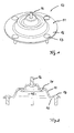
- unit bearing 10 is designed as a pneumatically damping bearing, which is used as an engine mount.
- the unit bearing 10 has a working chamber 15 which is bounded by a suspension spring 11.
- the suspension spring 11 consists of a fiber composite material, wherein the matrix material of the fiber composite material is a thermoplastic material with high temperature resistance.
- the Materixmaterial consists of polyphenylene sulfide (PPS). This material is characterized by a high heat resistance (depending on the type between 130 ° C and 240 ° C), low creep and high flexural strength. Furthermore, there is a very good hydrolysis resistance.
- the fiber composite material has a layer structure of fibers, wherein in the present case a single layer of a fabric made of glass fibers is provided. Alternatively, however, it is also possible to provide a layer composite with a plurality of stacked individual layers.
- the rotationally symmetrical suspension spring 11, which has a bell shape, is obtained by deep drawing, wherein the wave structure 14 is formed during deep drawing. Due to the wave structure 14, the suspension spring 11 has a high mobility.
- a bearing pin 12 is fixed, which is cast in the matrix material of the suspension spring 11.
- the determination of the unit bearing 10 takes place on the motor, not shown, of a motor vehicle.
- a plurality of fastening bolts 13 are provided which serve to fix the unit bearing 10 to the vehicle body.
- the unit bearing 10 is characterized by a high temperature resistance, which is achieved on the one hand by the temperature resistance of the suspension spring and on the other hand by the damping medium used (air).
- FIG. 3 illustrated another embodiment of an assembly bearing 10 according to the invention, the description of which already introduced reference numerals for the same or functionally identical parts is used, has a provided on the inside of the suspension spring 11 coating 17, which consists of a closed-cell foam plastic with high temperature resistance. For this purpose, for example, find EPDM use.
- the coating 17 a significant reduction of the volume of the working chamber 15 is achieved.
- the suspension spring 11 is supported on a bottom plate 18, in the center of a nozzle channel 19 is introduced.
- FIG. 4 illustrated further embodiment of an assembly bearing 10 according to the invention is designed as a hydraulic damping bearing.
- the suspension spring 11 in this case surrounds a working chamber 15 which is filled with a hydraulic fluid.
- the working chamber 15 is separated by means of an intermediate plate 21 from a compensation chamber 20.
- the compensation chamber 20 is bounded by an elastic compensation membrane 22.
- a damping channel 23 is the working chamber 15 with the compensation chamber 20 in hydraulic communication.
- a decoupling device 24 is provided for decoupling small amplitudes. This is designed as a compressible material layer, for example of a closed-cell foam.
- a suspension spring 11 which consists of a fiber composite material, wherein the matrix material of the fiber composite material is a thermoplastic material with high thermal stability, which is processable by deep drawing.
- the suspension spring used 11 causes a very low rate in preload, the low linear Freiweg is not significantly reduced over the life of the unit bearing 10.
- the unit bearing 10 is characterized by a low dynamic hardening.
Landscapes
- Engineering & Computer Science (AREA)
- General Engineering & Computer Science (AREA)
- Mechanical Engineering (AREA)
- Physics & Mathematics (AREA)
- Combustion & Propulsion (AREA)
- Transportation (AREA)
- Chemical & Material Sciences (AREA)
- Acoustics & Sound (AREA)
- Aviation & Aerospace Engineering (AREA)
- Arrangement Or Mounting Of Propulsion Units For Vehicles (AREA)
- Combined Devices Of Dampers And Springs (AREA)
- Vehicle Body Suspensions (AREA)
- Vibration Prevention Devices (AREA)
- Reinforced Plastic Materials (AREA)
- Support Of The Bearing (AREA)
Description
- Die vorliegende Erfindung betrifft ein dämpfendes Aggregatlager zur Verwendung als Motorlager für ein Kraftfahrzeug, mit einer Tragfeder, die eine mit einem Arbeitsmedium gefüllte Arbeitskammer begrenzt.
- Über derartige Aggregatlager werden Motor und Getriebe eines Kraftfahrzeugs mit der Karosserie verbunden. Derartige Lager müssen einerseits die auftretenden Gewichtskräfte, Momente und Massenkräfte des Aggregats abstützen und andererseits auftretende Geräusche und Schwingungen isolieren.
- Um diesen Aufgaben gerecht zu werden, sind derartige Aggregatlager als hydraulische oder pneumatisch dämpfende Lager ausgebildet. Diese weisen eine Tragfeder auf, die eine mit einem Arbeitsmedium gefüllte Arbeitskammer umgibt. Ein derartiges bekanntes Aggregatlager ist in der
DE 102 45 122 A1 beschrieben. Die von der Tragfeder begrenzte Arbeitskammer ist über einen Düsenkanal mit der Umgebung oder einer Ausgleichskammer verbunden. Die Tragfeder besteht aus einem gummielastischen, vulkanisierbaren Material. Der hierfür üblicherweise eingesetzte Naturkautschuk (NR) weist eine relativ geringe Dauertemperaturbeständigkeit von ca. 80 °C auf. Synthetischer Kautschuk (EPDM) weist eine Dauertemperaturbeständigkeit bis ca. 120 °C auf. Eine Beaufschlagung dieser Werkstoffe mit Dauertemperaturen oberhalb von 100°C beziehungsweise 140 °C führt zu einer Zerstörung des Werkstoffs. - Bei den heute in Kraftfahrzeugen zum Einsatz kommenden Hochleistungsmotoren, insbesondere in Verbindung mit aus Geräuschgründen gekapselten Motoren, ist eine höhere Temperaturbeständigkeit erforderlich.
- Aus der
EP 1 450 068 A2 ist bekannt, bei einem hydraulisch dämpfenden Lager eine Tragfeder aus Silikonkautschuk vorzusehen. Hiermit soll eine Temperaturbeständigkeit bis zu 200 °C erreicht werden können. Um eine ausreichende Beständigkeit gegenüber der Dämpfungsflüssigkeit zu erzielen, ist an der Innenwand der Tragfeder eine Schutzschicht aus EPDM vorgesehen. Derartige Tragfedern aus Silikonkautschuk weisen jedoch nur eine geringe Festigkeit auf. Weiterhin ist die Reißfestigkeit gering, so dass sich Risse schnell ausbreiten. - In der
DE 41 06 838 A1 wird ein dämpfendes Aggregatlager beschrieben, das einen ringförmigen Federkörper aus Faserverbundwerkstoff aufweist. Der Federkörper besteht aus mehreren Schichten kunstharzgetränkter Fasern, die hauptsächlich quer zur Beanspruchungsrichtung umlaufend gewickelt sind. Als verstärkende Faser kommen im Wesentlichen Glasfasern, aber auch Kohlefasern in Frage. Als aushärtbare Matrixmaterialien finden im wesentlichen Duroplaste oder auch Thermoplaste, beispielsweise Polyether-Etherketon, Verwendung. Der ringförmige Federkörper umgibt eine hydraulische Dämpfungseinrichtung, die eine von einem Faltenbalg umschlossene Arbeitskammer aufweist. Die Arbeitskammer ist über einen Dämpfungskanal mit einer Ausgleichskammer verbunden. Beide Kammern sind mit einer hydraulischen Flüssigkeit gefüllt. Ein derartiges Aggregatlager weist aufgrund des aus einem elastomeren Material bestehenden Faltenbalges eine begrenzte Temperaturbeständigkeit auf. - Der Erfindung liegt die Aufgabe zugrunde, ein Aggregatlager vorzuschlagen, das eine hohe Temperaturbeständigkeit bei geringem Satz unter Vorlast aufweist.
- Zur Lösung dieser Aufgabe wird bei einem Aggregatlager der eingangs genannten Art vorgeschlagen, dass die Tragfeder aus einem Faserverbundwerkstoff besteht, dass das Matrixmaterial des Faserverbundwerkstoffs ein thermoplastischer Kunststoff mit einer Temperaturbeständigkeit von größer gleich 130°C ist, der mittels Tiefziehen verarbeitbar ist, und dass die Tragfeder eine durch Tiefziehen erhaltene Glockenform aufweist, in die eine Wellenstruktur eingeformt ist.
- Bei dem erfindungsgemäßen Aggregatlager wird die Arbeitskammer durch die Tragfeder begrenzt, die gleichzeitig die auftretenden statischen Lasten aufnimmt. Da ein thermoplastischer Kunststoff hoher thermischer Stabilität verwendet wird, zeichnet sich das erfindungsgemäße Aggregatlager durch eine hohe Temperaturbeständigkeit aus. Weiterhin tritt nur ein geringer Satz unter Vorlast auf, wodurch der lineare Freiweg über die Lebensdauer nicht wesentlich verringert wird. Weiterhin bewirkt der Matrixwerkstoff, dass nur eine geringe dynamische Verhärtung auftritt. Die durch Tiefziehen hergestellte Tragfeder kann jede geeignete geometrische Form aufweisen. Insbesondere kann die Tragfeder ein rotationssymmetrisch oder rechteckförmig ausgebildet sein. Das erfindungsgemäße Aggregatlager zeichnet sich durch eine hohe Schwingungsfestigkeit und geringes Gewicht aus und ist weiterhin kostengünstig herstellbar.
- Vorteilhafte Ausgestaltungen sind Gegenstand der abhängigen Ansprüche.
- In vorteilhafter Ausgestaltung wird als Matrixmaterial Polyphenylensulfid (PPS) eingesetzt. Dieses Material zeichnet sich durch eine hohe Wärmeformbeständigkeit, geringe Kriechneigung und hohe Biegefestigkeit aus. Ebenso bietet Polyphenylensulfid eine sehr hohe Hydrolysebeständigkeit.
- In vorteilhafter Ausgestaltung wird vorgeschlagen, dass als verstärkende Fasern Glasfasern, Kohlefasern oder Aramidfasern eingesetzt werden.
- Vorteilhaft enthält die Tragfeder einen Lagenaufbau von Fasern, der als Gewebe und/oder unidirektionale Faserlage vorliegt.
- Vorteilhaft ist der Lagenaufbau als Einzelschicht oder mehrlagige Schicht ausgebildet.
- Die Tragfeder ist vorteilhaft an einer Boden-oder Zwischenplatte festgelegt. Die Bodenplatte kann hierbei auch als Strukturteil der Fahrzeugkarosserie vorliegen.
- Vorteilhaft ist ein Lagerbolzen an der Tragfeder festgelegt. Hierbei kann der Lagerbolzen vorteilhaft in das Matrixmaterial der Tragfeder eingegossen werden.
- Bei einem vorteilhaften Ausführungsbeispiel ist das Aggregatlager als pneumatisch dämpfendes Lager ausgebildet, wobei die Arbeitskammer mit einem Gas, insbesondere Luft, gefüllt ist. Durch die Verwendung von Luft als Dämpfungsmedium wird ebenfalls eine hohe Temperaturbeständigkeit von ≥ 130°C und eine Temperaturunabhängigkeit bis -30 °C erzielt. Weiterhin zeichnet sich ein derartiges Aggregatlager durch geringe Kosten gegenüber hydraulisch dämpfenden Lagern aus.
- Vorteilhaft ist die Arbeitskammer über einen Düsenkanal mit der Umgebung oder mit einer Ausgleichskammer verbunden.
- Um den Raum für die Arbeitskammer zu reduzieren, ist in vorteilhafter Ausgestaltung vorgesehen, dass eine Innenseite der Tragfeder mit einer das Volumen der Arbeitskammer verkleinernden Schicht versehen ist.
- In vorteilhafter Weiterbildung besteht die Schicht aus einem geschlossenzelligen Schaumkunststoff mit hoher Temperaturbeständigkeit.
- Bei einer weiteren vorteilhaften Ausgestaltung ist das Aggregatlager als hydraulisch dämpfendes Lager ausgebildet, wobei die Arbeitskammer mit einer hydraulischen Flüssigkeit gefüllt ist.
- Hierbei ist die Arbeitskammer über einen Dämpfungskanal mit einer Ausgleichskammer verbunden.
- Die Arbeitskammer ist von einer Ausgleichsmembran aus einem elastischen Material begrenzt.
- Da die Tragfeder aus Faserverbundwerkstoff eine relativ hohe Volumensteifigkeit aufweist, ist vorteilhaft eine Entkopplungseinrichtung zur Entkopplung kleiner Amplituden vorgesehen.
- Die Entkopplungseinrichtung kann in vorteilhafter Ausgestaltung als auf die Innenwand der Tragfeder aufgebrachte komprimierbare Materialschicht ausgebildet sein.
- Nachfolgend wird die Erfindung anhand von Ausführungsbeispielen erläutert, die in schematischer Weise in der Zeichnung dargestellt sind. Hierbei zeigen:
- Fig. 1
- eine perspektivische Darstellung eines ersten Ausführungsbeispieles eines erfindungsgemäßen Aggregatlagers, das als pneumatisch dämpfendes Lager ausgebildet ist,
- Fig. 2
- einen Vertikalschnitt durch
Fig. 1 , - Fig. 3
- einen Vertikalschnitt durch ein zweites Ausführungsbeispiel eines erfindungsgemäßen Aggregatlagers, und
- Fig. 4
- einen Vertikalschnitt durch ein drittes Ausführungsbeispiel eines erfindungsgemäßen Aggregatlagers.
- Das in den
Fig. 1 und 2 dargestellte Aggregatlager 10 ist als pneumatisch dämpfendes Lager ausgebildet, das als Motorlager Verwendung findet. Das Aggregatlager 10 weist eine Arbeitskammer 15 auf, die von einer Tragfeder 11 begrenzt ist. Die Tragfeder 11 besteht aus einem Faserverbundwerkstoff, wobei das Matrixmaterial des Faserverbundwerkstoffs ein thermoplastischer Kunststoff mit hoher Temperaturbeständigkeit ist. Vorliegend besteht das Materixmaterial aus Polyphenylensulfid (PPS). Dieses Material zeichnet sich durch eine hohe Wärmeformbeständigkeit (je nach Typ zwischen 130°C und 240°C), geringe Kriechneigung und hohe Biegefestigkeit aus. Weiterhin liegt eine sehr gute Hydrolysebeständigkeit vor. - Der Faserverbundwerkstoff weist einen Lagenaufbau von Fasern auf, wobei vorliegend eine Einzelschicht eines Gewebes aus Glasfasern vorgesehen ist. Alternativ kann jedoch auch ein Schichtenverbund mit mehreren gestapelten Einzelschichten vorgesehen sein.
- Die rotationssymmetrische Tragfeder 11, die eine Glockenform aufweist, wird durch Tiefziehen erhalten, wobei die Wellenstruktur 14 beim Tiefziehen eingeformt wird. Durch die Wellenstruktur 14 weist die Tragfeder 11 eine hohe Beweglichkeit auf.
- Im Zentrum der rotationssymmetrischen Tragfeder 11 ist ein Lagerbolzen 12 festgelegt, der in das Matrixmaterial der Tragfeder 11 eingegossen ist. An dem Lagerbolzen 12 erfolgt die Festlegung des Aggregatlagers 10 an dem nicht dargestellten Motor eines Kraftfahrzeugs.
- Am Rand 16 der Tragfeder 11 sind über den Umfang verteilt mehrere Befestigungsbolzen 13 vorgesehen, die der Festlegung des Aggregatlagers 10 an der Fahrzeugkarosserie dienen.
- Das Aggregatlager 10 zeichnet sich durch eine hohe Temperaturbeständigkeit aus, die einerseits durch die Temperaturbeständigkeit der Tragfeder und andererseits durch das verwendete Dämpfungsmedium (Luft) erzielt wird.
- Das in
Fig. 3 dargestellte weitere Ausführungsbeispiel eines erfindungsgemäßen Aggregatlagers 10, zu dessen Beschreibung die bereits eingeführten Bezugszeichen für gleiche oder funktionsgleiche Teile verwendet wird, weist eine an der Innenseite der Tragfeder 11 vorgesehene Beschichtung 17 auf, die aus einem geschlossenzelligen Schaumkunststoff mit hoher Temperaturbeständigkeit besteht. Hierzu kann beispielsweise EPDM Verwendung finden. Durch die Beschichtung 17 wird eine signifikante Verringerung des Volumens der Arbeitskammer 15 erreicht. - Die Tragfeder 11 stützt sich an einer Bodenplatte 18 ab, in deren Zentrum ein Düsenkanal 19 eingebracht ist.
- Das in
Fig. 4 dargestellte weitere Ausführungsbeispiel eines erfindungsgemäßen Aggregatlagers 10 ist als hydraulisch dämpfendes Lager ausgebildet. Die Tragfeder 11 umgibt hierbei eine Arbeitskammer 15, die mit einer hydraulischen Flüssigkeit gefüllt ist. Die Arbeitskammer 15 ist mittels einer Zwischenplatte 21 von einer Ausgleichskammer 20 getrennt. Die Ausgleichskammer 20 wird von einer elastischen Ausgleichsmembran 22 begrenzt. Über einen Dämpfungskanal 23 steht die Arbeitskammer 15 mit der Ausgleichskammer 20 in hydraulischer Verbindung. An der Innenseite der Tragfeder 11 ist eine Entkopplungseinrichtung 24 zur Entkopplung kleiner Amplituden vorgesehen. Diese ist als komprimierbare Materialschicht, beispielsweise aus einem geschlossenzelligen Schaumstoff, ausgebildet. - Bei allen vorstehend beschriebenen Ausführungsbeispielen kommt eine Tragfeder 11 zum Einsatz, die aus einem Faserverbundwerkstoff besteht, wobei das Matrixmaterial des Faserverbundwerkstoffs ein thermoplastischer Kunststoff mit hoher thermischer Stabilität ist, der mittels Tiefziehen verarbeitbar ist. Hierdurch wird eine hohe Temperaturbeständigkeit des Aggregatlagers von ≥ 130°C erzielt. Darüber hinaus bewirkt die zum Einsatz kommende Tragfeder 11 einen sehr geringen Satz in Vorlast, wobei der geringe lineare Freiweg auch über die Lebensdauer des Aggregatlagers 10 nicht wesentlich verringert wird. Weiterhin zeichnet sich das Aggregatlager 10 durch eine geringe dynamische Verhärtung aus.
-
- 10
- Aggregatlager
- 11
- Tragfeder
- 12
- Lagerbolzen
- 13
- Befestigungsbolzen
- 14
- Wellenstruktur
- 15
- Arbeitskammer
- 16
- Rand
- 17
- Beschichtung
- 18
- Bodenplatte
- 19
- Düsenkanal
- 20
- Ausgleichskammer
- 21
- Zwischenplatte
- 22
- Ausgleichsmembran
- 23
- Dämpfungskanal
- 24
- Entkopplungseinrichtung
Claims (16)
- Dämpfendes Aggregatlager (10) zur Verwendung als Motorlager für ein Kraftfahrzeug, mit einer Tragfeder (11), die eine mit einem Arbeitsmedium gefüllte Arbeitskammer (15) begrenzt, dadurch gekennzeichnet, dass die Tragfeder (11) aus einem Faserverbundwerkstoff besteht, dass das Matrixmaterial des Faserverbundwerkstoffs ein thermoplastischer Kunststoff mit einer Temperaturbeständigkeit von größer gleich 130°C ist, der mittels Tiefziehen verarbeitbar ist, und dass die Tragfeder (11) eine durch Tiefziehen erhaltene Glockenform aufweist, in die eine Wellenstruktur (14) eingeformt ist.
- Aggregatlager (10) nach Anspruch 1, dadurch gekennzeichnet, dass als Matrixmaterial Polyphenylensulfid (PPS) eingesetzt wird.
- Aggregatlager (10) nach Anspruch 1 oder 2, dadurch gekennzeichnet, dass als verstärkende Fasern Glasfasern, Kohlefasern oder Aramidfasern eingesetzt werden.
- Aggregatlager (10) nach Anspruch 1 bis 3, dadurch gekennzeichnet, dass die Tragfeder (11) einen Lagenaufbau von Fasern enthält, der als Gewebe und/oder unidirektionale Faserlage vorliegt.
- Aggregatlager (10) nach einem der Ansprüche 1 bis 4, dadurch gekennzeichnet, dass der Lagenaufbau als Einzelschicht oder mehrlagige Schicht ausgebildet ist.
- Aggregatlager (10) nach einem der Ansprüche 1 bis 5, dadurch gekennzeichnet, dass die Tragfeder (11) an einer Boden- oder Zwischenplatte (18,21) festgelegt ist.
- Aggregatlager (10) nach einem der Ansprüche 1 bis 5, dadurch gekennzeichnet, dass ein Lagerbolzen (12) in das Matrixmaterial der Tragfeder (11) eingegossen ist.
- Aggregatlager (10) nach einem der Ansprüche 1 bis 6, dadurch gekennzeichnet, dass das Aggregatlager (10) als pneumatisch dämpfendes Lager ausgebildet ist, wobei die Arbeitskammer (15) mit einem Gas, insbesondere Luft, gefüllt ist.
- Aggregatlager (10) nach Anspruch 7, dadurch gekennzeichnet, dass die Arbeitskammer (15) über einen Düsenkanal (19) mit der Umgebung oder mit einer Ausgleichskammer (22) verbunden ist.
- Aggregatlager (10) nach Anspruch 7 oder 8, dadurch gekennzeichnet, dass eine Innenseite der Tragfeder (11) mit einer das Volumen der Arbeitskammer (15) verkleinernden Beschichtung (17) versehen ist.
- Aggregatlager (10) nach Anspruch 10, dadurch gekennzeichnet, dass die Beschichtung aus einem geschlossenzelligen Schaumstoff mit hoher Temperaturbeständigkeit besteht.
- Aggregatlager (10) nach einem der Ansprüche 1 bis 7, dadurch gekennzeichnet, dass das Aggregatlager (10) als hydraulisch dämpfendes Lager ausgebildet ist, wobei die Arbeitskammer (15) mit einer hydraulischen Flüssigkeit gefüllt ist.
- Aggregatlager (10) nach Anspruch 11, dadurch gekennzeichnet, dass die Arbeitskammer (15) über einen Dämpfungskanal (23) mit einer Ausgleichskammer (20) verbunden ist.
- Aggregatlager (10) nach Anspruch 11 oder 12, dadurch gekennzeichnet, dass die Ausgleichskammer (20) von einer Ausgleichsmembran (22) aus einem elastischen Material begrenzt ist.
- Aggregatlager (10) nach einem der Ansprüche 1 bis 14, dadurch gekennzeichnet, dass eine Entkopplungseinrichtung (24) zur Entkopplung kleiner Amplituden vorgesehen ist.
- Aggregatlager (10) nach Anspruch 15, dadurch gekennzeichnet, dass die Entkopplungseinrichtung (24) als auf die Innenwand der Tragfeder (11) aufgebrachte komprimierbare Materialschicht aus einem geschlossenzelligen Schaumstoff ausgebildet ist.
Applications Claiming Priority (2)
| Application Number | Priority Date | Filing Date | Title |
|---|---|---|---|
| DE102006036343A DE102006036343B4 (de) | 2006-08-03 | 2006-08-03 | Dämpfendes Aggregatlager |
| PCT/EP2007/057985 WO2008015247A1 (de) | 2006-08-03 | 2007-08-01 | Dämpfendes aggregatlager |
Publications (2)
| Publication Number | Publication Date |
|---|---|
| EP2047138A1 EP2047138A1 (de) | 2009-04-15 |
| EP2047138B1 true EP2047138B1 (de) | 2013-03-13 |
Family
ID=38596897
Family Applications (1)
| Application Number | Title | Priority Date | Filing Date |
|---|---|---|---|
| EP07788150A Not-in-force EP2047138B1 (de) | 2006-08-03 | 2007-08-01 | Dämpfendes aggregatlager |
Country Status (6)
| Country | Link |
|---|---|
| US (1) | US20100025901A1 (de) |
| EP (1) | EP2047138B1 (de) |
| JP (1) | JP4802278B2 (de) |
| KR (1) | KR101393020B1 (de) |
| DE (1) | DE102006036343B4 (de) |
| WO (1) | WO2008015247A1 (de) |
Families Citing this family (9)
| Publication number | Priority date | Publication date | Assignee | Title |
|---|---|---|---|---|
| WO2011034882A1 (en) * | 2009-09-16 | 2011-03-24 | Illinois Tool Works Inc. | Pre-deformed thermoplastics spring and method of manufacture |
| US7441758B2 (en) | 2004-06-17 | 2008-10-28 | Illinois Tool Works Inc. | Load bearing surface |
| DE202008002110U1 (de) * | 2008-01-11 | 2009-06-25 | Recticel Schlafkomfort Gmbh | Auflagekonstruktion für eine Matratze |
| DE102008039592A1 (de) | 2008-08-25 | 2009-05-07 | Daimler Ag | Motorträger für eine Motorlagerung |
| KR101223531B1 (ko) | 2012-06-21 | 2013-01-17 | 김재운 | 복합형 와이어로프 방진장치 |
| FR2997152B1 (fr) | 2012-10-24 | 2015-01-02 | Anvis Sd France Sas | Support pneumatique. |
| KR101702449B1 (ko) | 2016-09-23 | 2017-02-03 | (주) 금성시스템 | 방진패드를 이용한 수배전반용 내진마운트 |
| DE102018220636A1 (de) * | 2018-11-29 | 2020-06-04 | Thyssenkrupp Ag | Verfahren zum Herstellen einer Feder-Baugruppe, Feder-Baugruppe und Feder einer Feder-Baugruppe |
| CN113565735B (zh) * | 2021-08-02 | 2022-08-23 | 珠海格力电器股份有限公司 | 一种压缩机减振脚垫控制方法及控制系统、减振脚垫 |
Family Cites Families (28)
| Publication number | Priority date | Publication date | Assignee | Title |
|---|---|---|---|---|
| DE3214997C2 (de) * | 1982-04-22 | 1986-12-18 | Audi AG, 8070 Ingolstadt | Kraftfahrzeugmotorlager |
| DE3443618A1 (de) * | 1984-11-29 | 1986-06-05 | Metzeler Kautschuk GmbH, 8000 München | Motorlager mit hydraulischer daempfung |
| JPS61171930A (ja) * | 1985-01-23 | 1986-08-02 | Bridgestone Corp | 防振装置 |
| US4788949A (en) * | 1986-04-04 | 1988-12-06 | Btr Plc A British Company | Mounting arrangement for vehicle engines |
| JPH03234937A (ja) * | 1990-02-13 | 1991-10-18 | Bridgestone Corp | 樹脂スプリング |
| FR2672351B1 (fr) * | 1991-02-04 | 1995-01-27 | Hutchinson | Support elastique a raideur variable. |
| DE4106838A1 (de) * | 1991-03-04 | 1992-09-10 | Metzeler Gimetall Ag | Daempfendes aggregatlager |
| DE4131771A1 (de) * | 1991-09-24 | 1993-04-01 | Metzeler Gimetall Ag | Elastisches motorlager |
| JPH08128497A (ja) * | 1994-10-28 | 1996-05-21 | Toyoda Gosei Co Ltd | 液封入防振装置 |
| DE19502242C1 (de) * | 1995-01-25 | 1996-01-18 | Metzeler Gimetall Ag | Motorlager mit steuerbarer Steifigkeit |
| JPH11148532A (ja) * | 1997-11-14 | 1999-06-02 | Porimatec Kk | 粘性流体封入ダンパ |
| JP3904310B2 (ja) * | 1997-12-18 | 2007-04-11 | ポリマテック株式会社 | 小型防振装置 |
| JP2000104774A (ja) * | 1998-09-25 | 2000-04-11 | Kurashiki Kako Co Ltd | 長寿命弾性構造体 |
| US6392982B1 (en) * | 1998-09-29 | 2002-05-21 | Mitsubishi Denki Kabushiki Kaisha | Corner part reinforcing device of disc device chassis |
| JP3796630B2 (ja) * | 1998-12-11 | 2006-07-12 | 東洋ゴム工業株式会社 | 液封入式防振装置 |
| DE19929303A1 (de) * | 1999-06-25 | 2000-12-28 | Wolf Woco & Co Franz J | Luftdämpfer |
| EP1096521A3 (de) * | 1999-10-27 | 2001-11-21 | Asahi Glass Co., Ltd. | Elektrischer Doppelschichtkondensator |
| WO2002023061A2 (en) * | 2000-09-14 | 2002-03-21 | Soucy Alan J | Vibration dampening apparatus |
| JP3731489B2 (ja) * | 2001-03-22 | 2006-01-05 | 東海ゴム工業株式会社 | 粘性流体封入ダンパ |
| WO2002081944A1 (fr) * | 2001-03-30 | 2002-10-17 | Toyo Tire & Rubber Co., Ltd. | Amortisseur de vibration de type a liquide etanche |
| EP1377760A1 (de) * | 2001-04-03 | 2004-01-07 | Woco Franz Josef Wolf & Co. Gmbh | Modulares lagersystem |
| JP3963346B2 (ja) * | 2001-07-17 | 2007-08-22 | 北辰工業株式会社 | エンジンマウント |
| JP4240923B2 (ja) * | 2001-12-14 | 2009-03-18 | ポリマテック株式会社 | ダンパーおよびメカシャーシの防振構造 |
| DE10245122B4 (de) * | 2002-09-27 | 2010-10-14 | Trelleborg Automotive Germany Gmbh | Pneumatisch dämpfendes Lager |
| DE10307680A1 (de) * | 2003-02-21 | 2004-09-30 | Carl Freudenberg Kg | Hydrolager |
| JP4738083B2 (ja) * | 2005-07-27 | 2011-08-03 | ポリマテック株式会社 | 粘性流体封入ダンパーおよび粘性流体封入ダンパーの取付構造 |
| JP4908798B2 (ja) * | 2005-08-05 | 2012-04-04 | ポリマテック株式会社 | 粘性流体封入ダンパー |
| DE102007007857B4 (de) * | 2007-02-16 | 2012-03-29 | Trelleborg Automotive Germany Gmbh | Hydraulisch dämpfendes Lager |
-
2006
- 2006-08-03 DE DE102006036343A patent/DE102006036343B4/de not_active Expired - Fee Related
-
2007
- 2007-08-01 EP EP07788150A patent/EP2047138B1/de not_active Not-in-force
- 2007-08-01 WO PCT/EP2007/057985 patent/WO2008015247A1/de not_active Ceased
- 2007-08-01 US US12/376,229 patent/US20100025901A1/en not_active Abandoned
- 2007-08-01 KR KR1020097004381A patent/KR101393020B1/ko not_active Expired - Fee Related
- 2007-08-01 JP JP2009522278A patent/JP4802278B2/ja not_active Expired - Fee Related
Also Published As
| Publication number | Publication date |
|---|---|
| DE102006036343B4 (de) | 2012-06-06 |
| EP2047138A1 (de) | 2009-04-15 |
| DE102006036343A1 (de) | 2008-02-07 |
| JP2009545710A (ja) | 2009-12-24 |
| KR20090035730A (ko) | 2009-04-10 |
| US20100025901A1 (en) | 2010-02-04 |
| WO2008015247A1 (de) | 2008-02-07 |
| KR101393020B1 (ko) | 2014-05-09 |
| JP4802278B2 (ja) | 2011-10-26 |
Similar Documents
| Publication | Publication Date | Title |
|---|---|---|
| WO2008015247A1 (de) | Dämpfendes aggregatlager | |
| EP1160483B1 (de) | Hydrolager | |
| WO2008110506A1 (de) | Pneumatisch dämpfendes lager | |
| US5193788A (en) | Damping bearing assembly | |
| DE2017999A1 (de) | Federelement, insbesondere zur elastischen Lagerung von Motoren | |
| EP0371196B1 (de) | Elastisches Lager für einen Körper | |
| EP1424506B1 (de) | Luftfederanordnung | |
| DE102017106289A1 (de) | Lagerbuchse | |
| DE19507519A1 (de) | Viskositäts-Drehschwingungsdämpfer | |
| DE19915798C2 (de) | Schaltbares, hydraulisch dämpfendes Lager | |
| DE10326625B4 (de) | Aktuatorbestückter Feder-Dämpfungsmechanismus | |
| DE69332787T2 (de) | Hochtemperatur-Flüssigkeitslager | |
| DE10262059B4 (de) | Tragarm | |
| DE102017004126A1 (de) | Drehschwingungsdämpfer | |
| DE19537462A1 (de) | Aggregatelager | |
| US20190338822A1 (en) | Mount assembly for a vehicle | |
| DE102007028041A1 (de) | Elastomerlager insbesondere für Fahrwerksbuchsen | |
| DE102012101561A1 (de) | Hydrolager | |
| EP2195179B1 (de) | Elastisches lager | |
| EP0670435B1 (de) | Elastisches Lager | |
| DE10117443B4 (de) | Feststofflager | |
| DE10137760A1 (de) | Luftlager | |
| DE102022211242B4 (de) | Hydrolager | |
| EP1600657B1 (de) | Tragarm | |
| DE102014002094A1 (de) | Lager zum Lagern eines Aggregats an einem Aufbau eines Kraftwagens |
Legal Events
| Date | Code | Title | Description |
|---|---|---|---|
| PUAI | Public reference made under article 153(3) epc to a published international application that has entered the european phase |
Free format text: ORIGINAL CODE: 0009012 |
|
| 17P | Request for examination filed |
Effective date: 20090211 |
|
| AK | Designated contracting states |
Kind code of ref document: A1 Designated state(s): AT BE BG CH CY CZ DE DK EE ES FI FR GB GR HU IE IS IT LI LT LU LV MC MT NL PL PT RO SE SI SK TR |
|
| AX | Request for extension of the european patent |
Extension state: AL BA HR MK RS |
|
| RAP1 | Party data changed (applicant data changed or rights of an application transferred) |
Owner name: TRELLEBORG AUTOMOTIVE GERMANY GMBH |
|
| 17Q | First examination report despatched |
Effective date: 20101115 |
|
| RAP1 | Party data changed (applicant data changed or rights of an application transferred) |
Owner name: TRELLEBORG AUTOMOTIVE GERMANY GMBH |
|
| DAX | Request for extension of the european patent (deleted) | ||
| GRAC | Information related to communication of intention to grant a patent modified |
Free format text: ORIGINAL CODE: EPIDOSCIGR1 |
|
| GRAP | Despatch of communication of intention to grant a patent |
Free format text: ORIGINAL CODE: EPIDOSNIGR1 |
|
| GRAS | Grant fee paid |
Free format text: ORIGINAL CODE: EPIDOSNIGR3 |
|
| GRAA | (expected) grant |
Free format text: ORIGINAL CODE: 0009210 |
|
| AK | Designated contracting states |
Kind code of ref document: B1 Designated state(s): AT BE BG CH CY CZ DE DK EE ES FI FR GB GR HU IE IS IT LI LT LU LV MC MT NL PL PT RO SE SI SK TR |
|
| REG | Reference to a national code |
Ref country code: GB Ref legal event code: FG4D Free format text: NOT ENGLISH |
|
| REG | Reference to a national code |
Ref country code: AT Ref legal event code: REF Ref document number: 600988 Country of ref document: AT Kind code of ref document: T Effective date: 20130315 Ref country code: CH Ref legal event code: EP |
|
| REG | Reference to a national code |
Ref country code: IE Ref legal event code: FG4D Free format text: LANGUAGE OF EP DOCUMENT: GERMAN |
|
| REG | Reference to a national code |
Ref country code: DE Ref legal event code: R096 Ref document number: 502007011469 Country of ref document: DE Effective date: 20130508 |
|
| PG25 | Lapsed in a contracting state [announced via postgrant information from national office to epo] |
Ref country code: BG Free format text: LAPSE BECAUSE OF FAILURE TO SUBMIT A TRANSLATION OF THE DESCRIPTION OR TO PAY THE FEE WITHIN THE PRESCRIBED TIME-LIMIT Effective date: 20130613 Ref country code: ES Free format text: LAPSE BECAUSE OF FAILURE TO SUBMIT A TRANSLATION OF THE DESCRIPTION OR TO PAY THE FEE WITHIN THE PRESCRIBED TIME-LIMIT Effective date: 20130624 Ref country code: SE Free format text: LAPSE BECAUSE OF FAILURE TO SUBMIT A TRANSLATION OF THE DESCRIPTION OR TO PAY THE FEE WITHIN THE PRESCRIBED TIME-LIMIT Effective date: 20130313 Ref country code: LT Free format text: LAPSE BECAUSE OF FAILURE TO SUBMIT A TRANSLATION OF THE DESCRIPTION OR TO PAY THE FEE WITHIN THE PRESCRIBED TIME-LIMIT Effective date: 20130313 |
|
| REG | Reference to a national code |
Ref country code: NL Ref legal event code: VDEP Effective date: 20130313 |
|
| REG | Reference to a national code |
Ref country code: LT Ref legal event code: MG4D |
|
| PG25 | Lapsed in a contracting state [announced via postgrant information from national office to epo] |
Ref country code: GR Free format text: LAPSE BECAUSE OF FAILURE TO SUBMIT A TRANSLATION OF THE DESCRIPTION OR TO PAY THE FEE WITHIN THE PRESCRIBED TIME-LIMIT Effective date: 20130614 Ref country code: FI Free format text: LAPSE BECAUSE OF FAILURE TO SUBMIT A TRANSLATION OF THE DESCRIPTION OR TO PAY THE FEE WITHIN THE PRESCRIBED TIME-LIMIT Effective date: 20130313 Ref country code: SI Free format text: LAPSE BECAUSE OF FAILURE TO SUBMIT A TRANSLATION OF THE DESCRIPTION OR TO PAY THE FEE WITHIN THE PRESCRIBED TIME-LIMIT Effective date: 20130313 Ref country code: LV Free format text: LAPSE BECAUSE OF FAILURE TO SUBMIT A TRANSLATION OF THE DESCRIPTION OR TO PAY THE FEE WITHIN THE PRESCRIBED TIME-LIMIT Effective date: 20130313 |
|
| PG25 | Lapsed in a contracting state [announced via postgrant information from national office to epo] |
Ref country code: CZ Free format text: LAPSE BECAUSE OF FAILURE TO SUBMIT A TRANSLATION OF THE DESCRIPTION OR TO PAY THE FEE WITHIN THE PRESCRIBED TIME-LIMIT Effective date: 20130313 Ref country code: SK Free format text: LAPSE BECAUSE OF FAILURE TO SUBMIT A TRANSLATION OF THE DESCRIPTION OR TO PAY THE FEE WITHIN THE PRESCRIBED TIME-LIMIT Effective date: 20130313 Ref country code: IS Free format text: LAPSE BECAUSE OF FAILURE TO SUBMIT A TRANSLATION OF THE DESCRIPTION OR TO PAY THE FEE WITHIN THE PRESCRIBED TIME-LIMIT Effective date: 20130713 Ref country code: EE Free format text: LAPSE BECAUSE OF FAILURE TO SUBMIT A TRANSLATION OF THE DESCRIPTION OR TO PAY THE FEE WITHIN THE PRESCRIBED TIME-LIMIT Effective date: 20130313 Ref country code: PT Free format text: LAPSE BECAUSE OF FAILURE TO SUBMIT A TRANSLATION OF THE DESCRIPTION OR TO PAY THE FEE WITHIN THE PRESCRIBED TIME-LIMIT Effective date: 20130715 Ref country code: RO Free format text: LAPSE BECAUSE OF FAILURE TO SUBMIT A TRANSLATION OF THE DESCRIPTION OR TO PAY THE FEE WITHIN THE PRESCRIBED TIME-LIMIT Effective date: 20130313 Ref country code: NL Free format text: LAPSE BECAUSE OF FAILURE TO SUBMIT A TRANSLATION OF THE DESCRIPTION OR TO PAY THE FEE WITHIN THE PRESCRIBED TIME-LIMIT Effective date: 20130313 |
|
| PG25 | Lapsed in a contracting state [announced via postgrant information from national office to epo] |
Ref country code: PL Free format text: LAPSE BECAUSE OF FAILURE TO SUBMIT A TRANSLATION OF THE DESCRIPTION OR TO PAY THE FEE WITHIN THE PRESCRIBED TIME-LIMIT Effective date: 20130313 Ref country code: CY Free format text: LAPSE BECAUSE OF FAILURE TO SUBMIT A TRANSLATION OF THE DESCRIPTION OR TO PAY THE FEE WITHIN THE PRESCRIBED TIME-LIMIT Effective date: 20130313 |
|
| PLBE | No opposition filed within time limit |
Free format text: ORIGINAL CODE: 0009261 |
|
| STAA | Information on the status of an ep patent application or granted ep patent |
Free format text: STATUS: NO OPPOSITION FILED WITHIN TIME LIMIT |
|
| PG25 | Lapsed in a contracting state [announced via postgrant information from national office to epo] |
Ref country code: DK Free format text: LAPSE BECAUSE OF FAILURE TO SUBMIT A TRANSLATION OF THE DESCRIPTION OR TO PAY THE FEE WITHIN THE PRESCRIBED TIME-LIMIT Effective date: 20130313 |
|
| 26N | No opposition filed |
Effective date: 20131216 |
|
| BERE | Be: lapsed |
Owner name: TRELLEBORG AUTOMOTIVE GERMANY G.M.B.H. Effective date: 20130831 |
|
| PG25 | Lapsed in a contracting state [announced via postgrant information from national office to epo] |
Ref country code: IT Free format text: LAPSE BECAUSE OF FAILURE TO SUBMIT A TRANSLATION OF THE DESCRIPTION OR TO PAY THE FEE WITHIN THE PRESCRIBED TIME-LIMIT Effective date: 20130313 |
|
| REG | Reference to a national code |
Ref country code: DE Ref legal event code: R097 Ref document number: 502007011469 Country of ref document: DE Effective date: 20131216 |
|
| REG | Reference to a national code |
Ref country code: CH Ref legal event code: PL |
|
| GBPC | Gb: european patent ceased through non-payment of renewal fee |
Effective date: 20130801 |
|
| PG25 | Lapsed in a contracting state [announced via postgrant information from national office to epo] |
Ref country code: MC Free format text: LAPSE BECAUSE OF FAILURE TO SUBMIT A TRANSLATION OF THE DESCRIPTION OR TO PAY THE FEE WITHIN THE PRESCRIBED TIME-LIMIT Effective date: 20130313 Ref country code: LI Free format text: LAPSE BECAUSE OF NON-PAYMENT OF DUE FEES Effective date: 20130831 Ref country code: CH Free format text: LAPSE BECAUSE OF NON-PAYMENT OF DUE FEES Effective date: 20130831 |
|
| REG | Reference to a national code |
Ref country code: IE Ref legal event code: MM4A |
|
| PG25 | Lapsed in a contracting state [announced via postgrant information from national office to epo] |
Ref country code: BE Free format text: LAPSE BECAUSE OF NON-PAYMENT OF DUE FEES Effective date: 20130831 |
|
| PG25 | Lapsed in a contracting state [announced via postgrant information from national office to epo] |
Ref country code: IE Free format text: LAPSE BECAUSE OF NON-PAYMENT OF DUE FEES Effective date: 20130801 Ref country code: GB Free format text: LAPSE BECAUSE OF NON-PAYMENT OF DUE FEES Effective date: 20130801 |
|
| REG | Reference to a national code |
Ref country code: AT Ref legal event code: MM01 Ref document number: 600988 Country of ref document: AT Kind code of ref document: T Effective date: 20130801 |
|
| PG25 | Lapsed in a contracting state [announced via postgrant information from national office to epo] |
Ref country code: AT Free format text: LAPSE BECAUSE OF NON-PAYMENT OF DUE FEES Effective date: 20130801 |
|
| PG25 | Lapsed in a contracting state [announced via postgrant information from national office to epo] |
Ref country code: MT Free format text: LAPSE BECAUSE OF FAILURE TO SUBMIT A TRANSLATION OF THE DESCRIPTION OR TO PAY THE FEE WITHIN THE PRESCRIBED TIME-LIMIT Effective date: 20130313 Ref country code: TR Free format text: LAPSE BECAUSE OF FAILURE TO SUBMIT A TRANSLATION OF THE DESCRIPTION OR TO PAY THE FEE WITHIN THE PRESCRIBED TIME-LIMIT Effective date: 20130313 |
|
| PG25 | Lapsed in a contracting state [announced via postgrant information from national office to epo] |
Ref country code: HU Free format text: LAPSE BECAUSE OF FAILURE TO SUBMIT A TRANSLATION OF THE DESCRIPTION OR TO PAY THE FEE WITHIN THE PRESCRIBED TIME-LIMIT; INVALID AB INITIO Effective date: 20070801 Ref country code: LU Free format text: LAPSE BECAUSE OF NON-PAYMENT OF DUE FEES Effective date: 20130801 |
|
| REG | Reference to a national code |
Ref country code: FR Ref legal event code: PLFP Year of fee payment: 10 |
|
| REG | Reference to a national code |
Ref country code: FR Ref legal event code: PLFP Year of fee payment: 11 |
|
| PGFP | Annual fee paid to national office [announced via postgrant information from national office to epo] |
Ref country code: FR Payment date: 20170823 Year of fee payment: 11 Ref country code: DE Payment date: 20170830 Year of fee payment: 11 |
|
| REG | Reference to a national code |
Ref country code: DE Ref legal event code: R119 Ref document number: 502007011469 Country of ref document: DE |
|
| PG25 | Lapsed in a contracting state [announced via postgrant information from national office to epo] |
Ref country code: DE Free format text: LAPSE BECAUSE OF NON-PAYMENT OF DUE FEES Effective date: 20190301 |
|
| PG25 | Lapsed in a contracting state [announced via postgrant information from national office to epo] |
Ref country code: FR Free format text: LAPSE BECAUSE OF NON-PAYMENT OF DUE FEES Effective date: 20180831 |