EP2047021B1 - Bonded nonwoven fibrous webs comprising softenable oriented semicrystalline polymeric fibers and apparatus and methods for preparing such webs - Google Patents
Bonded nonwoven fibrous webs comprising softenable oriented semicrystalline polymeric fibers and apparatus and methods for preparing such webs Download PDFInfo
- Publication number
- EP2047021B1 EP2047021B1 EP20070799607 EP07799607A EP2047021B1 EP 2047021 B1 EP2047021 B1 EP 2047021B1 EP 20070799607 EP20070799607 EP 20070799607 EP 07799607 A EP07799607 A EP 07799607A EP 2047021 B1 EP2047021 B1 EP 2047021B1
- Authority
- EP
- European Patent Office
- Prior art keywords
- web
- fibers
- temperature
- heated
- webs
- Prior art date
- Legal status (The legal status is an assumption and is not a legal conclusion. Google has not performed a legal analysis and makes no representation as to the accuracy of the status listed.)
- Not-in-force
Links
- 239000000835 fiber Substances 0.000 title claims description 241
- 238000000034 method Methods 0.000 title claims description 30
- 238000002844 melting Methods 0.000 claims description 89
- 230000008018 melting Effects 0.000 claims description 89
- 238000010438 heat treatment Methods 0.000 claims description 65
- 239000000463 material Substances 0.000 claims description 57
- 238000010791 quenching Methods 0.000 claims description 41
- 230000000171 quenching effect Effects 0.000 claims description 38
- -1 polyethylene Polymers 0.000 claims description 21
- 239000004743 Polypropylene Substances 0.000 claims description 18
- 229920001155 polypropylene Polymers 0.000 claims description 18
- 239000012530 fluid Substances 0.000 claims description 17
- 229920000139 polyethylene terephthalate Polymers 0.000 claims description 15
- 239000005020 polyethylene terephthalate Substances 0.000 claims description 15
- 238000012545 processing Methods 0.000 claims description 15
- 229920000642 polymer Polymers 0.000 claims description 14
- 238000007493 shaping process Methods 0.000 claims description 10
- 229920001778 nylon Polymers 0.000 claims description 6
- 239000004677 Nylon Substances 0.000 claims description 5
- 239000004698 Polyethylene Substances 0.000 claims description 3
- 229920000573 polyethylene Polymers 0.000 claims description 3
- 230000000717 retained effect Effects 0.000 claims description 3
- 238000003825 pressing Methods 0.000 claims description 2
- 239000002243 precursor Substances 0.000 claims 1
- 239000003570 air Substances 0.000 description 62
- 238000012360 testing method Methods 0.000 description 54
- 238000011282 treatment Methods 0.000 description 24
- 239000013078 crystal Substances 0.000 description 22
- 230000000877 morphologic effect Effects 0.000 description 19
- 238000000113 differential scanning calorimetry Methods 0.000 description 18
- 238000000465 moulding Methods 0.000 description 13
- 238000003490 calendering Methods 0.000 description 12
- 230000000694 effects Effects 0.000 description 9
- 238000001125 extrusion Methods 0.000 description 9
- 239000000203 mixture Substances 0.000 description 9
- 239000012080 ambient air Substances 0.000 description 8
- 230000008901 benefit Effects 0.000 description 8
- 230000000052 comparative effect Effects 0.000 description 8
- 239000007789 gas Substances 0.000 description 8
- 230000008859 change Effects 0.000 description 6
- 238000002425 crystallisation Methods 0.000 description 6
- 238000009826 distribution Methods 0.000 description 6
- 230000008569 process Effects 0.000 description 6
- 239000002178 crystalline material Substances 0.000 description 5
- 238000001938 differential scanning calorimetry curve Methods 0.000 description 5
- 238000005259 measurement Methods 0.000 description 5
- 239000000155 melt Substances 0.000 description 5
- 230000009467 reduction Effects 0.000 description 5
- 238000003860 storage Methods 0.000 description 5
- 238000001816 cooling Methods 0.000 description 4
- 238000001914 filtration Methods 0.000 description 4
- 230000006870 function Effects 0.000 description 4
- 230000003014 reinforcing effect Effects 0.000 description 4
- XLYOFNOQVPJJNP-UHFFFAOYSA-N water Substances O XLYOFNOQVPJJNP-UHFFFAOYSA-N 0.000 description 4
- 230000004323 axial length Effects 0.000 description 3
- 230000015572 biosynthetic process Effects 0.000 description 3
- 230000009477 glass transition Effects 0.000 description 3
- 230000001965 increasing effect Effects 0.000 description 3
- 239000007788 liquid Substances 0.000 description 3
- 238000004519 manufacturing process Methods 0.000 description 3
- 239000011159 matrix material Substances 0.000 description 3
- 238000002360 preparation method Methods 0.000 description 3
- 229920006126 semicrystalline polymer Polymers 0.000 description 3
- 238000003892 spreading Methods 0.000 description 3
- 230000007480 spreading Effects 0.000 description 3
- 229920001410 Microfiber Polymers 0.000 description 2
- 239000000654 additive Substances 0.000 description 2
- 238000013459 approach Methods 0.000 description 2
- 238000004581 coalescence Methods 0.000 description 2
- 230000001427 coherent effect Effects 0.000 description 2
- 230000001351 cycling effect Effects 0.000 description 2
- 230000002708 enhancing effect Effects 0.000 description 2
- 230000004438 eyesight Effects 0.000 description 2
- 239000004744 fabric Substances 0.000 description 2
- 238000001595 flow curve Methods 0.000 description 2
- 238000009499 grossing Methods 0.000 description 2
- 239000001257 hydrogen Substances 0.000 description 2
- 229910052739 hydrogen Inorganic materials 0.000 description 2
- 239000012528 membrane Substances 0.000 description 2
- 239000003658 microfiber Substances 0.000 description 2
- 239000005026 oriented polypropylene Substances 0.000 description 2
- 238000007670 refining Methods 0.000 description 2
- 239000007787 solid Substances 0.000 description 2
- 238000007711 solidification Methods 0.000 description 2
- 230000008023 solidification Effects 0.000 description 2
- 238000005507 spraying Methods 0.000 description 2
- 239000000126 substance Substances 0.000 description 2
- 239000000758 substrate Substances 0.000 description 2
- OVSKIKFHRZPJSS-UHFFFAOYSA-N 2,4-D Chemical compound OC(=O)COC1=CC=C(Cl)C=C1Cl OVSKIKFHRZPJSS-UHFFFAOYSA-N 0.000 description 1
- 229920002302 Nylon 6,6 Polymers 0.000 description 1
- 238000003917 TEM image Methods 0.000 description 1
- 238000002441 X-ray diffraction Methods 0.000 description 1
- 230000035508 accumulation Effects 0.000 description 1
- 238000009825 accumulation Methods 0.000 description 1
- 230000000996 additive effect Effects 0.000 description 1
- 239000000853 adhesive Substances 0.000 description 1
- 230000001070 adhesive effect Effects 0.000 description 1
- 229920006125 amorphous polymer Polymers 0.000 description 1
- 230000009286 beneficial effect Effects 0.000 description 1
- 239000007767 bonding agent Substances 0.000 description 1
- 238000009960 carding Methods 0.000 description 1
- 239000012612 commercial material Substances 0.000 description 1
- 239000000470 constituent Substances 0.000 description 1
- 238000010276 construction Methods 0.000 description 1
- 239000000112 cooling gas Substances 0.000 description 1
- 230000008025 crystallization Effects 0.000 description 1
- 230000008021 deposition Effects 0.000 description 1
- 238000010586 diagram Methods 0.000 description 1
- 229920006240 drawn fiber Polymers 0.000 description 1
- 239000000975 dye Substances 0.000 description 1
- 238000004049 embossing Methods 0.000 description 1
- 239000003517 fume Substances 0.000 description 1
- 230000014759 maintenance of location Effects 0.000 description 1
- 230000004048 modification Effects 0.000 description 1
- 238000012986 modification Methods 0.000 description 1
- 238000001565 modulated differential scanning calorimetry Methods 0.000 description 1
- 239000012768 molten material Substances 0.000 description 1
- 230000003287 optical effect Effects 0.000 description 1
- 239000011236 particulate material Substances 0.000 description 1
- 239000008188 pellet Substances 0.000 description 1
- 230000002085 persistent effect Effects 0.000 description 1
- 239000000049 pigment Substances 0.000 description 1
- 229920001225 polyester resin Polymers 0.000 description 1
- 239000004645 polyester resin Substances 0.000 description 1
- 230000001681 protective effect Effects 0.000 description 1
- 238000005086 pumping Methods 0.000 description 1
- 230000008707 rearrangement Effects 0.000 description 1
- 230000010076 replication Effects 0.000 description 1
- 229920005989 resin Polymers 0.000 description 1
- 239000011347 resin Substances 0.000 description 1
- 238000005204 segregation Methods 0.000 description 1
- 238000000926 separation method Methods 0.000 description 1
- 229910001220 stainless steel Inorganic materials 0.000 description 1
- 239000010935 stainless steel Substances 0.000 description 1
- 238000007669 thermal treatment Methods 0.000 description 1
- 150000003673 urethanes Chemical class 0.000 description 1
- 238000011179 visual inspection Methods 0.000 description 1
- 238000005303 weighing Methods 0.000 description 1
- 238000004736 wide-angle X-ray diffraction Methods 0.000 description 1
Images


Classifications
-
- D—TEXTILES; PAPER
- D04—BRAIDING; LACE-MAKING; KNITTING; TRIMMINGS; NON-WOVEN FABRICS
- D04H—MAKING TEXTILE FABRICS, e.g. FROM FIBRES OR FILAMENTARY MATERIAL; FABRICS MADE BY SUCH PROCESSES OR APPARATUS, e.g. FELTS, NON-WOVEN FABRICS; COTTON-WOOL; WADDING ; NON-WOVEN FABRICS FROM STAPLE FIBRES, FILAMENTS OR YARNS, BONDED WITH AT LEAST ONE WEB-LIKE MATERIAL DURING THEIR CONSOLIDATION
- D04H3/00—Non-woven fabrics formed wholly or mainly of yarns or like filamentary material of substantial length
- D04H3/08—Non-woven fabrics formed wholly or mainly of yarns or like filamentary material of substantial length characterised by the method of strengthening or consolidating
- D04H3/16—Non-woven fabrics formed wholly or mainly of yarns or like filamentary material of substantial length characterised by the method of strengthening or consolidating with bonds between thermoplastic filaments produced in association with filament formation, e.g. immediately following extrusion
-
- D—TEXTILES; PAPER
- D04—BRAIDING; LACE-MAKING; KNITTING; TRIMMINGS; NON-WOVEN FABRICS
- D04H—MAKING TEXTILE FABRICS, e.g. FROM FIBRES OR FILAMENTARY MATERIAL; FABRICS MADE BY SUCH PROCESSES OR APPARATUS, e.g. FELTS, NON-WOVEN FABRICS; COTTON-WOOL; WADDING ; NON-WOVEN FABRICS FROM STAPLE FIBRES, FILAMENTS OR YARNS, BONDED WITH AT LEAST ONE WEB-LIKE MATERIAL DURING THEIR CONSOLIDATION
- D04H17/00—Felting apparatus
-
- D—TEXTILES; PAPER
- D04—BRAIDING; LACE-MAKING; KNITTING; TRIMMINGS; NON-WOVEN FABRICS
- D04H—MAKING TEXTILE FABRICS, e.g. FROM FIBRES OR FILAMENTARY MATERIAL; FABRICS MADE BY SUCH PROCESSES OR APPARATUS, e.g. FELTS, NON-WOVEN FABRICS; COTTON-WOOL; WADDING ; NON-WOVEN FABRICS FROM STAPLE FIBRES, FILAMENTS OR YARNS, BONDED WITH AT LEAST ONE WEB-LIKE MATERIAL DURING THEIR CONSOLIDATION
- D04H3/00—Non-woven fabrics formed wholly or mainly of yarns or like filamentary material of substantial length
- D04H3/08—Non-woven fabrics formed wholly or mainly of yarns or like filamentary material of substantial length characterised by the method of strengthening or consolidating
-
- Y—GENERAL TAGGING OF NEW TECHNOLOGICAL DEVELOPMENTS; GENERAL TAGGING OF CROSS-SECTIONAL TECHNOLOGIES SPANNING OVER SEVERAL SECTIONS OF THE IPC; TECHNICAL SUBJECTS COVERED BY FORMER USPC CROSS-REFERENCE ART COLLECTIONS [XRACs] AND DIGESTS
- Y10—TECHNICAL SUBJECTS COVERED BY FORMER USPC
- Y10T—TECHNICAL SUBJECTS COVERED BY FORMER US CLASSIFICATION
- Y10T428/00—Stock material or miscellaneous articles
- Y10T428/24—Structurally defined web or sheet [e.g., overall dimension, etc.]
- Y10T428/24802—Discontinuous or differential coating, impregnation or bond [e.g., artwork, printing, retouched photograph, etc.]
- Y10T428/2481—Discontinuous or differential coating, impregnation or bond [e.g., artwork, printing, retouched photograph, etc.] including layer of mechanically interengaged strands, strand-portions or strand-like strips
-
- Y—GENERAL TAGGING OF NEW TECHNOLOGICAL DEVELOPMENTS; GENERAL TAGGING OF CROSS-SECTIONAL TECHNOLOGIES SPANNING OVER SEVERAL SECTIONS OF THE IPC; TECHNICAL SUBJECTS COVERED BY FORMER USPC CROSS-REFERENCE ART COLLECTIONS [XRACs] AND DIGESTS
- Y10—TECHNICAL SUBJECTS COVERED BY FORMER USPC
- Y10T—TECHNICAL SUBJECTS COVERED BY FORMER US CLASSIFICATION
- Y10T428/00—Stock material or miscellaneous articles
- Y10T428/249921—Web or sheet containing structurally defined element or component
- Y10T428/249953—Composite having voids in a component [e.g., porous, cellular, etc.]
-
- Y—GENERAL TAGGING OF NEW TECHNOLOGICAL DEVELOPMENTS; GENERAL TAGGING OF CROSS-SECTIONAL TECHNOLOGIES SPANNING OVER SEVERAL SECTIONS OF THE IPC; TECHNICAL SUBJECTS COVERED BY FORMER USPC CROSS-REFERENCE ART COLLECTIONS [XRACs] AND DIGESTS
- Y10—TECHNICAL SUBJECTS COVERED BY FORMER USPC
- Y10T—TECHNICAL SUBJECTS COVERED BY FORMER US CLASSIFICATION
- Y10T428/00—Stock material or miscellaneous articles
- Y10T428/29—Coated or structually defined flake, particle, cell, strand, strand portion, rod, filament, macroscopic fiber or mass thereof
- Y10T428/2913—Rod, strand, filament or fiber
- Y10T428/2933—Coated or with bond, impregnation or core
- Y10T428/2964—Artificial fiber or filament
- Y10T428/2967—Synthetic resin or polymer
- Y10T428/2969—Polyamide, polyimide or polyester
-
- Y—GENERAL TAGGING OF NEW TECHNOLOGICAL DEVELOPMENTS; GENERAL TAGGING OF CROSS-SECTIONAL TECHNOLOGIES SPANNING OVER SEVERAL SECTIONS OF THE IPC; TECHNICAL SUBJECTS COVERED BY FORMER USPC CROSS-REFERENCE ART COLLECTIONS [XRACs] AND DIGESTS
- Y10—TECHNICAL SUBJECTS COVERED BY FORMER USPC
- Y10T—TECHNICAL SUBJECTS COVERED BY FORMER US CLASSIFICATION
- Y10T442/00—Fabric [woven, knitted, or nonwoven textile or cloth, etc.]
- Y10T442/30—Woven fabric [i.e., woven strand or strip material]
- Y10T442/3325—Including a foamed layer or component
-
- Y—GENERAL TAGGING OF NEW TECHNOLOGICAL DEVELOPMENTS; GENERAL TAGGING OF CROSS-SECTIONAL TECHNOLOGIES SPANNING OVER SEVERAL SECTIONS OF THE IPC; TECHNICAL SUBJECTS COVERED BY FORMER USPC CROSS-REFERENCE ART COLLECTIONS [XRACs] AND DIGESTS
- Y10—TECHNICAL SUBJECTS COVERED BY FORMER USPC
- Y10T—TECHNICAL SUBJECTS COVERED BY FORMER US CLASSIFICATION
- Y10T442/00—Fabric [woven, knitted, or nonwoven textile or cloth, etc.]
- Y10T442/60—Nonwoven fabric [i.e., nonwoven strand or fiber material]
- Y10T442/608—Including strand or fiber material which is of specific structural definition
- Y10T442/614—Strand or fiber material specified as having microdimensions [i.e., microfiber]
- Y10T442/619—Including other strand or fiber material in the same layer not specified as having microdimensions
-
- Y—GENERAL TAGGING OF NEW TECHNOLOGICAL DEVELOPMENTS; GENERAL TAGGING OF CROSS-SECTIONAL TECHNOLOGIES SPANNING OVER SEVERAL SECTIONS OF THE IPC; TECHNICAL SUBJECTS COVERED BY FORMER USPC CROSS-REFERENCE ART COLLECTIONS [XRACs] AND DIGESTS
- Y10—TECHNICAL SUBJECTS COVERED BY FORMER USPC
- Y10T—TECHNICAL SUBJECTS COVERED BY FORMER US CLASSIFICATION
- Y10T442/00—Fabric [woven, knitted, or nonwoven textile or cloth, etc.]
- Y10T442/60—Nonwoven fabric [i.e., nonwoven strand or fiber material]
- Y10T442/608—Including strand or fiber material which is of specific structural definition
- Y10T442/614—Strand or fiber material specified as having microdimensions [i.e., microfiber]
- Y10T442/626—Microfiber is synthetic polymer
-
- Y—GENERAL TAGGING OF NEW TECHNOLOGICAL DEVELOPMENTS; GENERAL TAGGING OF CROSS-SECTIONAL TECHNOLOGIES SPANNING OVER SEVERAL SECTIONS OF THE IPC; TECHNICAL SUBJECTS COVERED BY FORMER USPC CROSS-REFERENCE ART COLLECTIONS [XRACs] AND DIGESTS
- Y10—TECHNICAL SUBJECTS COVERED BY FORMER USPC
- Y10T—TECHNICAL SUBJECTS COVERED BY FORMER US CLASSIFICATION
- Y10T442/00—Fabric [woven, knitted, or nonwoven textile or cloth, etc.]
- Y10T442/60—Nonwoven fabric [i.e., nonwoven strand or fiber material]
- Y10T442/637—Including strand or fiber material which is a monofilament composed of two or more polymeric materials in physically distinct relationship [e.g., sheath-core, side-by-side, islands-in-sea, fibrils-in-matrix, etc.] or composed of physical blend of chemically different polymeric materials or a physical blend of a polymeric material and a filler material
- Y10T442/641—Sheath-core multicomponent strand or fiber material
-
- Y—GENERAL TAGGING OF NEW TECHNOLOGICAL DEVELOPMENTS; GENERAL TAGGING OF CROSS-SECTIONAL TECHNOLOGIES SPANNING OVER SEVERAL SECTIONS OF THE IPC; TECHNICAL SUBJECTS COVERED BY FORMER USPC CROSS-REFERENCE ART COLLECTIONS [XRACs] AND DIGESTS
- Y10—TECHNICAL SUBJECTS COVERED BY FORMER USPC
- Y10T—TECHNICAL SUBJECTS COVERED BY FORMER US CLASSIFICATION
- Y10T442/00—Fabric [woven, knitted, or nonwoven textile or cloth, etc.]
- Y10T442/60—Nonwoven fabric [i.e., nonwoven strand or fiber material]
- Y10T442/68—Melt-blown nonwoven fabric
-
- Y—GENERAL TAGGING OF NEW TECHNOLOGICAL DEVELOPMENTS; GENERAL TAGGING OF CROSS-SECTIONAL TECHNOLOGIES SPANNING OVER SEVERAL SECTIONS OF THE IPC; TECHNICAL SUBJECTS COVERED BY FORMER USPC CROSS-REFERENCE ART COLLECTIONS [XRACs] AND DIGESTS
- Y10—TECHNICAL SUBJECTS COVERED BY FORMER USPC
- Y10T—TECHNICAL SUBJECTS COVERED BY FORMER US CLASSIFICATION
- Y10T442/00—Fabric [woven, knitted, or nonwoven textile or cloth, etc.]
- Y10T442/60—Nonwoven fabric [i.e., nonwoven strand or fiber material]
- Y10T442/69—Autogenously bonded nonwoven fabric
Definitions
- This invention relates to fibrous webs that comprise oriented semicrystalline polymeric fibers having unique softening characteristics that provide the webs with enhanced bonding and shaping properties; and the invention further relates to apparatus and methods for preparing such webs.
- the present invention provides new nonwoven fibrous webs comprising oriented semicrystalline polymeric fibers that are bonded to form a coherent and handleable web and that further may be softened while retaining orientation and fiber structure.
- the new nonwoven webs may be shaped and calendered in beneficial ways.
- the new webs are provided by a new method that takes advantage of the morphology of oriented semicrystalline polymeric fibers (the class of semicrystalline polymers is well defined and well known and is distinguished from amorphous polymers, which have no detectable crystalline order; crystallinity can be readily detected by differential scanning calorimetry, x-ray diffraction, density, and other methods; "orientation" or “oriented” means that at least portions of the polymeric molecules of the fibers are aligned lengthwise of the fibers as a result of passage of the fibers through equipment such as an attenuation chamber or mechanical drawing machine; the presence of orientation in fibers can be detected by various means including birefringence measurements or wide-angle x-ray diffraction).
- Conventional oriented semicrystalline polymeric fibers may be considered to have two different kinds of molecular regions or phases: a first kind of phase that is characterized by a relatively large presence of highly ordered, or strain-induced, crystalline domains, and a second kind of phase that is characterized by a relatively large presence of domains of lower crystalline order (e.g., not chain-extended) and domains that are amorphous, though the latter may have some order or orientation of a degree insufficient for crystallinity.
- These two different kinds of phases which need not have sharp boundaries and can exist in mixture with one another, have different kinds of properties.
- the different properties include different melting and/or softening characteristics: the first phase characterized by a larger presence of highly ordered crystalline domains melts at a temperature (e.g., the melting point of a chain-extended crystalline domain) that is higher than the temperature at which the second phase melts or softens (e.g., the glass transition temperature of the amorphous domain as modified by the melting points of the lower-order crystalline domains).
- a temperature e.g., the melting point of a chain-extended crystalline domain
- softens e.g., the glass transition temperature of the amorphous domain as modified by the melting points of the lower-order crystalline domains.
- the first phase is termed herein the "crystallite-characterized phase” because its melting characteristics are more strongly influenced by the presence of the higher order crystallites, giving the phase a higher melting point than it would have without the crystallites present;
- the second phase is termed the "amorphous-characterized phase” because it softens at a lower temperature influenced by amorphous molecular domains or of amorphous material interspersed with lower-order crystalline domains.
- the bonding characteristics of conventional oriented semicrystalline polymeric fibers are influenced by the existence of the two different kinds of molecular phases.
- the heating operation has the effect of increasing the crystallinity of the fibers, e.g., through accretion of molecular material onto existing crystal structure or further ordering of the ordered amorphous portions.
- the presence of lower-order crystalline material in the amorphous-characterized phase promotes such crystal growth, and promotes it as added lower-order crystalline material.
- the result of the increased lower-order crystallinity is to limit softening and flowability of the fibers during a bonding operation.
- oriented semicrystalline polymeric fibers are subjected to a controlled heating and quenching operation in which the fibers, and the described phases, are morphologically refined to give the fibers new properties and utility.
- this heating and quenching operation the fibers are first heated for a short controlled time at a rather high temperature, often as high or higher than the nominal melting point of the polymeric material from which the fibers are made.
- the heating is at a temperature and for a time sufficient for the amorphous-characterized phase of the fibers to melt or soften while the crystallite-characterized phase remains unmelted (we use the terminology "melt or soften” because amorphous portions of an amorphous-characterized phase generally are considered to soften at their glass transition temperature, while crystalline portions melt at their melting point; the most effective heat treatment in a method of the invention occurs when a web is heated to cause melting of crystalline material in the amorphous-characterized phase of constituent fibers).
- the heated fibers are immediately and rapidly cooled to quench and freeze them in a refined or purified morphological form.
- morphological refining means simply changing the morphology of oriented semicrystalline polymeric fibers; but we understand the refined morphological structure of the treated fibers of the invention as follows (we do not wish to be bound by statements herein of our "understanding,” which generally involve some theoretical considerations).
- the amount of molecular material of the phase susceptible to undesirable (softening-impeding) crystal growth is not as great as it was before treatment.
- amorphous-characterized phase has experienced a kind of cleansing or reduction of morphological structure that would lead to undesirable increases in crystallinity in conventional untreated fibers during a thermal bonding operation; e.g., the variety or distribution of morphological forms has been reduced, the morphological structure simplified, and a kind of segregation of the morphological structure into more discernible amorphous-characterized and crystallite-characterized phases has occurred.
- Treated fibers of the invention are capable of a kind of "repeatable softening,” meaning that the fibers, and particularly the amorphous-characterized phase of the fibers, will undergo to some degree a repeated cycle of softening and resolidifying as the fibers are exposed to a cycle of raised and lowered temperature within a temperature region lower than that which would cause melting of the whole fiber.
- autogenous bonding is defined as bonding between fibers at an elevated temperature as obtained in an oven or with a through-air bonder without application of solid contact pressure such as in point-bonding or calendering).
- the cycling of softening and resolidifying may not continue indefinitely, but it is usually sufficient that the fibers may be initially bonded by exposure to heat, e.g., during a heat treatment according to the invention, and later heated again to cause re-softening and further bonding, or, if desired, other operations, such as calendering or re-shaping.
- oriented semicrystalline fibers to soften and autogenously bond at temperatures substantially below their nominal melting point is, so far as known, unprecedented and remarkable.
- a softening opens the way to many new processes and products.
- One example is the ability to reshape the web, e.g., by calendering it to a smooth surface or molding it to a nonplanar shape as for a face mask.
- Another example is the ability to bond a web at lower temperatures, which for example may allow bonding without causing some other undesirable change in the web.
- reshaping or bonding can be performed at a temperature 15 °C below the nominal melting point of the polymeric material of the fibers.
- the invention provides a method for molding a web comprised of oriented semicrystalline monocomponent polymeric fibers, the method comprising a) morphologically refining the web in a heating and quenching operation so that the web is capable of developing autogenous bonds at a temperature less than the Nominal Melting Point of the fibers; b) placing the web in a mold; and c) subjecting the web to a molding temperature effective to lastingly convert the web into the mold shape.
- the amorphous-characterized phase Given the role of the amorphous-characterized phase in achieving bonding of fibers, e.g., providing the material of softening and bonding of fibers, we sometimes call the amorphous-characterized phase the "bonding" phase.
- the crystallite-characterized phase of the fiber has its own different role, namely to reinforce the basic fiber structure of the fibers.
- the crystallite-characterized phase generally can remain unmelted during a bonding or like operation because its melting point is higher than the melting/softening point of the amorphous-characterized phase, and it thus remains as an intact matrix that extends throughout the fiber and supports the fiber structure and fiber dimensions.
- bonding fibers means adhering the fibers together firmly, so they generally do not separate when the web is subjected to normal handling
- the basic discrete fiber structure is retained over the length of the fibers between intersections and bonds; preferably, the cross-section of the fibers remains unchanged over the length of the fibers between intersections or bonds formed during the operation.
- calendering of a web of the invention may cause fibers to be reconfigured by the pressure and heat of the calendering operation (thereby causing the fibers to permanently retain the shape pressed upon them during calendering and make the web more uniform in thickness), the fibers generally remain as discrete fibers with a consequent retention of desired web porosity, filtration, and insulating properties.
- crystallite-characterized phase Given the reinforcing role of the crystallite-characterized phase as described, we sometimes refer to it as the "reinforcing" phase or "holding” phase.
- the crystallite-characterized phase also is understood to undergo morphological refinement during a treatment of the invention, for example, to change the amount of higher-order crystalline structure.
- DSC differential scanning calorimetry
- the first heat measures characteristics of a nonwoven fibrous web of the invention directly after its completion, i.e., without it having experienced additional thermal treatment (plots referred to in this specification are generally first-heat plots unless otherwise identified).
- the second heat measures the basic properties of the material of the web, with any features that were imposed on the basic material by the processing to which the material was subjected during manufacture and treatment of a web of the invention having been erased by the melting of the sample that occurred during the first heat.
- MDSC TM testing produces three different plots or signal traces as shown in Figure 6 : Plot A, a "non-reversing heat flow” plot (which is informative as to kinetic events occurring within the test sample); Plot B, a “reversing heat flow” plot (e.g., related to heat-capacity); and Plot C, a "total heat flow” plot like the typical DSC plot and showing the net heat flow occurring in the sample as it is heated through the DSC test regime.
- Plot A a "non-reversing heat flow” plot (which is informative as to kinetic events occurring within the test sample)
- Plot B a "reversing heat flow” plot (e.g., related to heat-capacity)
- Plot C a "total heat flow” plot like the typical DSC plot and showing the net heat flow occurring in the sample as it is heated through the DSC test regime.
- Plot A of Figure 6 reveals an exothermic peak T CC reflecting cold-crystallization, and T CP , a "crystal-perfection peak," reflecting an exotherm occurring as crystal structure in the sample further rearranges into a more perfect or larger crystal structure.
- Plot B is generally used to determine the glass transition temperature T g of the polymer, though a deflection representative of T g also appears on Plot C.
- Figure 7 shows both the first-heat and the second-heat total-heat-flow plots (Plots A and B, respectively) for a representative material of the invention (in this case for Example 5).
- One useful item of information obtained from the second-heat plot (Plot B) is information on the basic melting point of the polymeric material used in making a nonwoven web of the invention.
- the basic melting point is seen as an endotherm on the second-heat plot or scan occurring at about the temperature where the most ordered crystals of the sample melt.
- the peak M is the melting point peak for the test sample, and the peak maximum M' is regarded as the nominal melting point for the sample.
- the "Nominal Melting Point" for a polymer or a polymeric fiber is defined as the peak maximum of a second-heat, total-heat-flow DSC plot in the melting region of the polymer or fiber if there is only one maximum in that region; and, if there is more than one maximum indicating more than one melting point (e.g., because of the presence of two distinct crystalline phases), as the temperature at which the highest-amplitude melting peak occurs.
- Another useful item of information is the temperature at which melting of a test sample begins, i.e., the onset temperature of melting of the sample.
- This temperature is defined for purposes herein as the point where the tangent drawn from the point of maximum slope of the melting peak on the total-heat-flow plot intersects with the baseline of the plot (BL in Figure 7 ; the line where there are neither positive nor negative heat flows).
- T o the onset melting temperature for the polymeric material of Example 5 is shown on Plot B (preferably T o is determined from the second-heat plot).
- Another useful item of information is received from the first-heat nonreversing-heat-flow signal.
- This item of information is conveyed by exothermic peaks in the signal occurring at and around the melting of, respectively, the amorphous-characterized phase and the crystallite-characterized phase. These exothermic peaks, often referred to as the crystal-perfection peaks, represent thermal energy produced as molecules within the respective phases rearrange during heating of the test sample.
- thermal energy is given off, and the amount of thermal energy given off varies as the test temperature increases toward the melting point of crystallites in the amorphous-characterized phase.
- the molecular material of the phase melts and the thermal energy given off declines, leaving a peak maximum occurring at a temperature that may be seen as a distinguishing characteristic of the state of the molecular material of the amorphous-characterized phase of the test nonwoven web.
- a similar phenomenon occurs for the crystallite-characterized phase, and a peak maximum develops that is characteristic of the state of the molecular material of the crystallite-characterized phase. This peak occurs at a temperature higher than the temperature of the peak maximum for the amorphous-characterized phase.
- nylon can undergo changes during thermal processing such as experienced in DSC testing because of rather strong hydrogen bonding between adjacent molecules, with the result that the melting point of a nylon test sample may be raised during the first-heat DSC test. The higher melting point becomes an artifact of the test that must be accounted for (discussed further below).
- Plot A is the first-heat nonreversing-heat-flow plot for a web of the invention (Example 4) and Plot B is the second-heat nonreversing-heat-flow plot for the sample.
- T CP crystal perfection peak
- T CC cold-crystallization peak
- a nonwoven web of the invention can be understood to comprise oriented softenable semicrystalline polymeric fibers that exhibit at least one Distinguishing DSC Characteristic, whereby the fibers may be further bonded or thermomechanically shaped while retaining their fiber structure.
- a new method of the invention by which a new web of the invention can be provided comprises, briefly, the steps of 1) providing a nonwoven fibrous web that comprises oriented semicrystalline polymeric fibers, and 2) subjecting the web to a controlled heating and quenching operation that includes a) forcefully passing through the web a fluid heated to a temperature greater than the onset melting temperature of the material of the fiber for a time too short to melt the whole fibers (causing the fibers to lose their discrete fibrous nature; preferably, the time of heating is too short to cause a significant distortion of the fiber cross-section as indicated in the Melting Distortion test described in the working examples later herein), and b) immediately quenching the web by forcefully passing through the web a fluid having sufficient heat capacity to solidify the fibers (i.e., to solidify the amorphous-characterized phase of the fibers softened/melted during heat treatment), which temperature is generally at least 50 °C less than the Nominal Melting Point.
- the fluids passed through the web are gaseous streams,
- step (2) of the described method includes passing the web on a conveyor through a device (which can be termed a quenched flow heater, as discussed subsequently) that provides a focused, heated gaseous (typically air) stream issuing from the heater under pressure and engaging one side of the web, with gas-withdrawal apparatus on the other side of the web to assist in drawing the heated gas through the web; generally the heated stream is knife-like or curtain-like (such as emanates from an elongated or rectangular slot), extends across the width of the web, and is uniform (i.e., has a uniformity in temperature and flow so as to heat fibers in the web with a useful degree of uniformity).
- a device which can be termed a quenched flow heater, as discussed subsequently
- a focused, heated gaseous (typically air) stream issuing from the heater under pressure and engaging one side of the web, with gas-withdrawal apparatus on the other side of the web to assist in drawing the heated gas through the web
- the heated stream is knife-like or curtain
- the heated stream is in some respects similar to the heated stream from a "through-air bonder” or “hot-air knife,” though it may be subjected to special controls that modulate the flow, causing the heated gas to be distributed uniformly and at a controlled rate through the width of the web to thoroughly, uniformly and rapidly heat the fibers of the web to a usefully high temperature.
- gas-withdrawal apparatus is positioned downwcb from the heated gaseous stream so as to draw a cooling gas or other fluid, e.g., ambient air, through the web promptly after it has been heated and thereby rapidly quench the fibers.
- a cooling gas or other fluid e.g., ambient air
- the length of heating is controlled, e.g., by the length of the heating region along the path of web travel and by the speed at which the web is moved through the heating region to the cooling region, to cause the intended melting/softening of the amorphous-characterized phase without melting of the whole fiber.
- Webs of the invention may be used by themselves, e.g., for filtration media, decorative fabric, or a protective or cover stock. Or they may be used in combination with other webs or structures, c.g., as a support for other fibrous layers deposited or laminated onto the web, as in a multilayer filtration media, or a substrate onto which a membrane may be cast. They may be processed after preparation as by passing them through smooth calendering rolls to form a smooth-surfaced web, or through shaping apparatus to form them into three-dimensional shapes.
- Hot-air knives are commonly used for bonding fibrous webs.
- One example, intended to accomplish a light bonding to prepare a web for further processing is found in Arnold et al., U. S. Patent No. 5,707,468 , which teaches "subjecting a just produced spunbond web to a high flow rate, heated stream of air ... to very lightly bond the fibers of the web together.”
- the temperature of the heated air is insufficient to melt the polymer in the fiber even at the surface of the fiber, but is only intended to be sufficient to soften the fiber slightly (e.g., see column 5, lines 25-27).
- the heating operation is only intended to cause the fibers to immediately become very lightly bonded together so that the web has sufficient integrity for further processing. No heating and quenching like that used in the present invention is described.
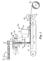
- Figures 1-5 show an illustrative apparatus for carrying out the invention as part of a direct-web production method and apparatus, in which a fiber-forming polymeric material is converted into a web in one essentially direct operation.
- Figure 1 is a schematic overall side view;
- Figures 2 and 3 are enlarged views of fiber-forming portions of the Figure 1 apparatus;
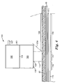
- Figure 4 is an enlarged and expanded side view of a portion of the apparatus shown in Figure 1 adapted to heat and quench the collected web;
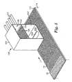
- Figure 5 is a perspective view showing parts of the heating and quenching apparatus and a web being treated, with parts being broken away.
- the invention can also be practiced by treating preformed webs, in which case apparatus for carrying out the invention might consist essentially only of apparatus as shown in Figures 4 and 5 .
- fiber-forming material is brought to an extrusion head 10 -- in this illustrative apparatus, by introducing a polymeric fiber-forming material into a hopper 11, melting the material in an extruder 12, and pumping the molten material into the extrusion head 10 through a pump 13.
- Solid polymeric material in pellet or other particulate form is most commonly used and melted to a liquid, pumpable state.
- the extrusion head 10 may be a conventional spinnerette or spin pack, generally including multiple orifices arranged in a regular pattern, e.g., straightline rows.
- Filaments 15 of fiber-forming liquid are extruded from the extrusion head and conveyed to a processing chamber or attenuator 16.
- the distance 17 the extruded filaments 15 travel before reaching the attenuator 16 can vary, as can the conditions to which they are exposed.
- quenching streams of air or other gas 18 are presented to the extruded filaments to reduce the temperature of the extruded filaments 15.
- the streams of air or other gas may be heated to facilitate drawing of the fibers.
- a first air stream 18a blown transversely to the filament stream which may remove undesired gaseous materials or fumes released during extrusion
- a second quenching air stream 18b that achieves a major desired temperature reduction.
- the quenching air may be sufficient to solidify the extruded filaments 15 before they reach the attenuator 16. In other cases the extruded filaments are still in a softened or molten condition when they enter the attenuator. Alternatively, no quenching streams are used; in such a case ambient air or other fluid between the extrusion head 10 and the attenuator 16 may be a medium for any change in the extruded filaments before they enter the attenuator.
- the filaments 15 pass through the attenuator 16, as discussed in more detail below, and then exit onto a collector 19 where they are collected as a mass of fibers 20.
- the collector 19 is generally porous and a gas-withdrawal device 14 can be positioned below the collector to assist deposition of fibers onto the collector.
- the distance 21 between the attenuator exit and the collector may be varied to obtain different effects.
- extruded filaments or fibers may be subjected to a number of additional processing steps not illustrated in Figure 1 , e.g., further drawing, spraying, etc. After collection the collected mass 20 is generally heated and quenched according to the invention; but the mass could be wound into a storage roll for later heating and quenching if desired.
- the mass 20 may be conveyed to other apparatus such as calenders, embossing stations, laminators, cutters and the like; or it may be passed through drive rolls 22 and wound into a storage roll 23.
- the mass 20 of fibers is carried by the collector 19 through a heating and quenching operation as illustrated in Figures 1 , 4 and 5 ; for shorthand purposes we often refer to the apparatus pictured particularly in Figures 4 and 5 as a quenched flow heater, or more simply a quenched heater.
- the collected mass 20 is first passed under a controlled-heating device 100 mounted above the collector 19.
- the exemplary heating device 100 comprises a housing 101 that is divided into an upper plenum 102 and a lower plenum 103.
- the upper and lower plenums are separated by a plate 104 perforated with a series of holes 105 that are typically uniform in size and spacing.
- a gas typically air
- the plate 104 functions as a flow-distribution means to cause air fed into the upper plenum to be rather uniformly distributed when passed through the plate into the lower plenum 103.
- Other useful flow-distribution means include fins, baffles, manifolds, air dams, screens or sintered plates, i.e., devices that even the distribution of air.
- the bottom wall 108 of the lower plenum 103 is formed with an elongated, rectangular slot 109 through which a curtain-like stream 110 of heated air from the lower plenum is blown onto the mass 20 traveling on the collector 19 bellow the heating device 100 (the mass 20 and collector 19 are shown partly broken away in Fig. 5 ).
- the gas-exhaust device 14 preferably extends sufficiently to lie under the slot 109 of the heating device 100 (as well as extending downweb a distance 118 beyond the heated stream 110 and through an area marked 120, as will be discussed below). Heated air in the plenum is thus under an internal pressure within the plenum 103, and at the slot 109 it is further under the exhaust vacuum of the gas-exhaust device 14.
- a perforated plate 111 may be positioned under the collector 19 to impose a kind of back pressure or flow-restriction means that contributes to spreading of the stream 110 of heated air in a desired uniformity over the width or heated area of the collected mass 20.
- Other useful flow-restriction means include screens or sintered plates.
- the number, size and density of openings in the plate 111 may be varied in different areas to achieve desired control. Large amounts of air pass through the fiber-forming apparatus and must be disposed of in the region 115 as the fibers reach the collector. Sufficient air passes through the web and collector in the region 116 to hold the web in place under the various streams of processing air. And sufficient openness is needed in the plate under the heat-treating region 117 and quenching region 118 to allow treating air to pass through the web, while sufficient resistance remains to assure that the air is more evenly distributed.
- the amount and temperature of heated air passed through the mass 20 is chosen to lead to an appropriate modification of the morphology of the fibers. Particularly, the amount and temperature are chosen so that the fibers are heated to a) cause melting/softening of significant molecular portions within a cross-section of the fiber, e.g., the amorphous-characterized phase of the fiber as discussed above (this often can be stated, without reference to phases, simply as heating to cause melting of lower-order crystallites within the fiber), but b) not cause complete melting of another significant phase, e.g., the crystallite-characterized phase as discussed above.
- the fibers as a whole remain unmelted, e.g., the fibers generally retain the same fiber shape and dimensions as they had before treatment.
- Crystal structure may have been added to the existing crystal structure; or in the case of highly ordered fibers (see, for example, the highly drawn fibers of Examples 11-14 and C14-20), crystal structure may have been removed to create distinguishable amorphous-characterized and crystallite-characterized phases.
- the temperature-time conditions should be controlled over the whole heated area of the mass.
- the temperature of the stream 110 of heated air passing through the web is within a range of 5 °C, and preferably within 2 or even 1 °C, across the width of the mass being treated (the temperature of the heated air is often measured for convenient control of the operation at the entry point for the heated air into the housing 101, but it also can be measured adjacent the collected web with thermocouples).
- the heating apparatus is operated to maintain a steady temperature in the stream over time, e.g., by rapidly cycling the heater on and off to avoid over- or under-heating.
- the temperature is held within one degree Centigrade of the intended temperature when measured at one second intervals.
- the mass is subjected to quenching immediately after the application of the stream 110 of heated air.
- a quenching can generally be obtained by drawing ambient air over and through the mass 20 as the mass leaves the controlled hot air stream 110.
- Numeral 120 in Figure 4 represents an area in which ambient air is drawn by the air-exhaust device through the web.
- the gas-exhaust device 14 extends along the collector for a distance 118 beyond the heating device 100 to assure thorough cooling and quenching of the whole mass 20 in the area 120.
- Air can be drawn under the base of the housing 101, e.g., in the area 120a marked on Figure 4 of the drawings, so that it reaches the web directly after the web leaves the hot air stream 110.
- An aim of the quenching is to rapidly remove heat from the web and the fibers and thereby limit the extent and nature of crystallization or molecular ordering that will subsequently occur in the fibers.
- a heating and quenching operation of the invention is performed while a web is moved through the operation on a conveyor, and quenching is performed before the web is wound into a storage roll at the end of the operation.
- the times of treatment depend on the speed at which a web is moved through an operation, but generally the total heating and quenching operation is performed in a minute or less, and preferably in less than 15 seconds.
- the amorphous-characterized phase is understood to be frozen into a more purified crystalline form, with reduced molecular material that can interfere with softening, or repeatable softening, of the fibers.
- the mass is cooled by a gas at a temperature at least 50°C less than the Nominal Melting Point; also the quenching gas is desirably applied for a time on the order of at least one second, desirably for a time at least two or three times as long as the heated stream engaged the web. In any event the quenching gas or other fluid has sufficient heat capacity to rapidly solidify the fibers.
- Other fluids that may be used include water sprayed onto the fibers, e.g., heated water or steam to heat the fibers, and relatively cold water to quench the fibers.
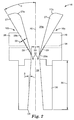
- FIG 2 is an enlarged side view of a representative device 16 for orienting the fibers that are collected as a web or matte and then treated according to the invention.
- the illustrative orienting or processing device 16 often called herein an attenuator, comprises two movable halves or sides 16a and 16b separated so as to define between them the processing chamber 24: the facing surfaces of the sides 16a and 16b form the walls of the chamber.
- Figure 3 is a top and somewhat schematic view at a different scale showing the representative attenuator 16 and some of its mounting and support structure.
- the processing or attenuation chamber 24 is generally an elongated slot, having a transverse length 25 (transverse to the path of travel of filaments through the attenuator), which can vary depending on the number of filaments being processed.
- the representative attenuator 16 includes slanted entry walls 27, which define an entrance space or throat 24a of the attenuation chamber 24.
- the entry walls 27 preferably are curved at the entry edge or surface 27a to smooth the entry of air streams carrying the extruded filaments 15.
- the walls 27 are attached to a main body portion 28, and may be provided with a recessed area 29 to establish a gap 30 between the body portion 28 and wall 27.
- Air may be introduced into the gaps 30 through conduits 31, creating air knives (represented by the arrows 32) that increase the velocity of the filaments traveling through the attenuator, and that also have a further quenching effect on the filaments.
- the attenuator body 28 is preferably curved at 28a to smooth the passage of air from the air knife 32 into the passage 24.
- the angle ( ⁇ ) of the surface 28b of the attenuator body can be selected to determine the desired angle at which the air knife impacts a stream of filaments passing through the attenuator.
- the air knives may be disposed further within the chamber.
- the attenuation chamber 24 may have a uniform gap width (the horizontal distance 33 on the page of Figure 2 between the two attenuator sides is herein called the gap width) over its longitudinal length through the attenuator (the dimension along a longitudinal axis 26 through the attenuation chamber is called the axial length).
- the gap width may vary along the length of the attenuator chamber.
- the attenuation chamber is narrower internally within the attenuator; e.g., as shown in Figure 2 , the gap width 33 at the location of the air knives is the narrowest width, and the attenuation chamber expands in width along its length toward the exit opening 34, e.g., at an angle ⁇ .
- the attenuation chamber is defined by straight or flat walls; in such embodiments the spacing between the walls may be constant over their length, or alternatively the walls may slightly diverge (preferred) or converge over the axial length of the attenuation chamber. In all these cases, the walls defining the attenuation chamber arc regarded as parallel herein, because the deviation from exact parallelism is relatively slight. As illustrated in Figure 2 , the walls defining the main portion of the longitudinal length of the passage 24 may take the form of plates 36 that are separate from, and attached to, the main body portion 28.
- the length of the attenuation chamber 24 can be varied to achieve different effects; variation is especially useful with the portion between the air knives 32 and the exit opening 34, sometimes called herein the chute length 35.
- the angle between the chamber walls and the axis 26 may be wider near the exit 34 to change the distribution of fibers onto the collector; or structure such as deflector surfaces, Coanda curved surfaces, and uneven wall lengths may be used at the exit to achieve a desired spreading or other distribution of fibers.
- the gap width, chute length, attenuation chamber shape, etc. are chosen in conjunction with the material being processed and the mode of treatment desired to achieve desired effects. For example, longer chute lengths may be useful to increase the crystallinity of prepared fibers. Conditions are chosen and can be widely varied to process the extruded filaments into a desired fiber form.
- the two sides 16a and 16b of the representative attenuator 16 are each supported through mounting blocks 37 attached to linear bearings 38 that slide on rods 39.
- the bearing 38 has a low-friction travel on the rod through means such as axially extending rows of ball-bearings disposed radially around the rod, whereby the sides 16a and 16b can readily move toward and away from one another.
- the mounting blocks 37 are attached to the attenuator body 28 and a housing 40 through which air from a supply pipe 41 is distributed to the conduits 31 and air knives 32.
- air cylinders 43a and 43b are connected, respectively, to the attenuator sides 16a and 16b through connecting rods 44 and apply a clamping force pressing the attenuator sides 16a and 16b toward one another.
- the clamping force is chosen in conjunction with the other operating parameters so as to balance the pressure existing within the attenuation chamber 24.
- the clamping force and the force acting internally within the attenuation chamber to press the attenuator sides apart as a result of the gaseous pressure within the attenuator are in balance or equilibrium under preferred operating conditions.
- Filamentary material can be extruded, passed through the attenuator and collected as finished fibers while the attenuator parts remain in their established equilibrium or steady-state position and the attenuation chamber or passage 24 remains at its established equilibrium or steady-state gap width.
- movement of the attenuator sides or chamber walls generally occurs only when there is a perturbation of the system.
- a perturbation may occur when a filament being processed breaks or tangles with another filament or fiber.
- breaks or tangles are often accompanied by an increase in pressure within the attenuation chamber 24, e.g., because the forward end of the filament coming from the extrusion head or the tangle is enlarged and creates a localized blockage of the chamber 24.
- the increased pressure is sufficient to force the attenuator sides or chamber walls 16a and 16b to move away from one another.
- the end of the incoming filament or the tangle can pass through the attenuator, whereupon the pressure in the attenuation chamber 24 returns to its steady-state value before the perturbation, and the clamping pressure exerted by the air cylinders 43 returns the attenuator sides to their steady-state position.
- Other perturbations causing an increase in pressure in the attenuation chamber include "drips," i.e., globular liquid pieces of fiber-forming material falling from the exit of the extrusion head upon interruption of an extruded filament, or accumulations of extruded filamentary material that may engage and stick to the walls of the attenuation chamber or to previously deposited fiber-forming material.
- Fibers useful in the invention may be prepared on apparatus in which the walls of the attenuator arc fixed and unmovable, or do not move in practice.
- the invention may be practiced on webs prepared by procedures completely different from the direct-web preparation techniques illustrated in Figure 1 .
- heating and quenching operations of the invention can be performed on separately prepared webs such as webs of air-laid staple fibers or preformed spunbond webs.
- any nonwoven fibrous web comprising oriented semicrystalline fibers may be treated according to the invention.
- webs prepared by such known techniques as those described in U. S. Patent Nos. 3,692,618 ; 4,340,563 ; and 4,820,459 may be treated.
- apparatus for heating and quenching as described or claimed in this patent specification (which to our knowledge is a novel apparatus) has other uses in addition to those described herein.
- the apparatus can be used to obtain bonded webs without interest or intention to cause morphological refinement or to subject the treated web to subsequent operations making use of such refinement.
- One example of such a use is taught in U.S. Patent Application Serial No. 11/461,192, filed July 31, 2006 .
- That patent application describes a nonwoven fibrous web comprising a matrix of continuous meltspun fibers and separately prepared microfibers dispersed among the meltspun fibers; the web can be treated with apparatus of the present patent application to cause bonding of the meltspun fibers to form a coherent or self-sustaining matrix; such a treated web may or may not be subjected to subsequent operations that take advantage of morphological refinement of the meltspun fibers.
- any semicrystalline fiber-forming polymeric material may be used in preparing fibers and webs of the invention, including the polymers commonly used in commercial fiber formation such as polyethylene, polypropylene, polyethylene terephthalate, nylon, and urethanes.
- the specific polymers listed here are examples only, and a wide variety of other polymeric or fiber-forming materials are useful.
- Fibers also may be formed from blends of materials, including materials into which certain additives have been added, such as pigments or dyes.
- Bicomponent fibers such as core-sheath or side-by-side bicomponent fibers, may be used ("bicomponent” herein includes fibers with two or more components, each occupying a separate part of the cross-section of the fiber and extending over the length of the fiber).
- monocomponent fibers which have many benefits (e.g., less complexity in manufacture and composition; "monocomponent” fibers have essentially the same composition across their cross-section; monocomponent includes blends or additive-containing materials, in which a continuous phase of uniform composition extends across the cross-section and over the length of the fiber) and can be conveniently bonded and given added bondability and shapeability by the invention.
- Different fiber-forming materials may be extruded through different orifices of the extrusion head so as to prepare webs that comprise a mixture of fibers.
- other materials are introduced into a stream of fibers prepared according to the invention before or as the fibers are collected so as to prepare a blended web.
- other staple fibers may be blended in the manner taught in U.S. Patent No.
- Various processes conventionally used as adjuncts to fiber-forming processes may be used in connection with filaments as they enter or exit from the attenuator, such as spraying of finishes or other materials onto the filaments, application of an electrostatic charge to the filaments, application of water mists, etc.
- various materials may be added to a collected web, including bonding agents, adhesives, finishes, and other webs or films.
- the fibers prepared by a method of the invention may range widely in diameter. Microfiber sizes (about 10 micrometers or less in diameter) may be obtained and offer several benefits; but fibers of larger diameter can also be prepared and are useful for certain applications; often the fibers are 20 micrometers or less in diameter. Fibers of circular cross-section are most often prepared, but other cross-sectional shapes may also be used. Depending on the operating parameters chosen, e.g., degree of solidification from the molten state before entering the attenuator, the collected fibers may be rather continuous or essentially discontinuous.
- the orientation of the polymer chains in the fibers can be influenced by selection of operating parameters, such as degree of solidification of filament entering the attenuator, velocity and temperature of air stream introduced into the attenuator by the air knives, and axial length, gap width and shape (because, for example, shape influences the venturi effect) of the attenuator passage.
- the amorphous-characterized phase in a fiber of the invention takes the form of a multitude of minute phases distributed throughout the cross-section of the fiber. Wherever their location however, at least portions of the amorphous-dominated phase appear to be at or near the exterior of the fibers, because of their participation in bonding of the fibers.
- a web of the invention generally has a degree of bonding sufficient for the web to be handled, e.g., removed from the collection screen and wound into a storage roll. But as discussed above, additional bonding is possible and is often performed, e.g., to more permanently stabilize the web, or to shape it, including providing it with a nonplanar shape or smoothing its surfaces.
- any additional bonding is most typically done in a through-air-bonder, but also can be done in an oven or as part of a calendering or shaping operation. (Although there is seldom any reason to do so, bonding can also be accomplished or assisted by use of extraneous bonding materials included in the web during formation or applied after web-formation.)
- heat is generally applied in a narrow range, precisely selected to cause softening of the amorphous-characterized phase of a fiber to achieve bonding, while leaving the crystallite-characterized phase substantially unaffected.
- the unaffected crystallite-characterized phase thus can have a reinforcing function, e.g., it can function to retain fiber shape during the bonding operation, so that aside from bond regions the fiber retains its discrete fibrous form and the web retains its basic fibrous structure.
- the fiber can retain its original (i.e., pre-bonding) fiber cross-section over its length outside bond regions, where there typically is some flow and coalescence of material from adjacent bonded fibers.
- shaping it is meant reconfiguring the web into a persistent new configuration, i.e., a self-sustaining configuration that the web will generally retain during use.
- shaping means smoothing one or both surfaces of the web and in some cases compacting the web.
- shaping involves configuring the web into a nonplanar shape such as perhaps a cup-shape for use in a face mask. Again the fibrous character of the web is retained during shaping, though the fibers may receive a somewhat different cross-section through the pressure of the shaping operation.
- fibers of the invention can provide other useful properties and features.
- the improved morphological purity of the fibers as found in the amorphous-characterized phase may make the fibers chemically more reactive, enhancing use of the fiber for such purposes as grafting substrates.
- the fact that a web of the invention can be bonded without addition of an extraneous material is another important advantage, enhancing utility of the webs as membrane supports, electrochemical cell separators, filtration media, etc.
- the invention is further illustrated in the following illustrative examples.
- Several examples are identified as comparative examples, because they do not show certain properties (such as softening, bonding, or DSC characteristics) desired for bondability, moldability, etc.; but the comparative examples may be useful for other purposes and may exhibit novel and nonobvious character.
- Apparatus as shown in Figures 1-5 was used to prepare fibrous webs from polypropylene and polyethylene terephthalate.
- Examples 1-3 and C1-C6 were prepared from polypropylene (PP) having a Nominal Melting Point of 160.5 °C and a melt flow index (MFI) of 70 (Dypro 3860x polypropylene resin supplied by Total Chemical of Houston, Texas).
- Examples 4-6 and C7-C8 were prepared from polyethylene terephthalate (PET) having a Nominal Melting Point of 254.1 °C and an intrinsic viscosity of 0.61 (3M Polyester Resin 65100).
- the clamping pressure reported in the table was sufficient that the walls of the attenuator remained generally fixed during preparation of fibers.
- Apparatus parameters not reported in the table are as follows.
- the plate 104 of the quenched flow heater (QFH) in Figure 5 contained 1/4-inch-diameter (0.64 centimeter) holes at a uniform spacing of 3/8 inch (0.95 centimeter) such as to constitute 40 % of the plate area.
- the collector 19 was a 50-inch-wide (1.27 meter), 40-mesh stainless steel woven belt in a chevron pattern with 0.43mm by 0.60mm openings (Style 2055 from Albany International Engineered Fabrics of Portland TN).
- Fibers were deposited on the collector belt to form a mass 20 having a width of about 22 inches (55.9 centimeters).
- Section 115 of the plate 111 underlying the belt 19 had a machine-direction length of 14.5 inches (36.8 centimeters) and contained 1.59-milliimeter-diameter holes on centers spaced 2.78 millimeters at a uniform spacing such as to constitute 30 % of the plate area;
- section 116 had a length of 23.5 inches (about 60 centimeters) and contained 1.59-milliimeter-diameter holes on centers spaced 3.18 millimeters at a uniform spacing such as to constitute 23 % of the plate area;
- sections 117 and 118 together had a length of about 9 inches (about 23 centimeters) and contained 3.97-millimeter-diameter holes at a uniform spacing with centers spaced 4.76 millimeters such that the holes constituted 63 % of the plate area;
- the machine-direction length of section 117
- the air-exhaust duct 14 had a width (transverse to the machine direction, which is the direction of movement of the collector belt) of 22 inches (55.9 centimeters) and a length sufficient for the distance 118 in Figure 4 to be about 19 centimeters.
- the heating face velocity reported in the table was measured at the center of the slot 109 at a point about one-half inch (1.27 centimeter) above the mass using a hot-wire anemometer; 10 measurements were taken over the width of the zone and arithmetically averaged.
- the cooling face velocity was measured in the same manner at the center (along the machine-direction axis) of the area 120 in Figure 4 .
- the temperatures reported in Table 1 for the heating zones 1-6 are temperatures of air entering the box 101 from the conduits 107. There were six conduits 107 and temperature of input air was measured at the entry point to the box 101 by open-junction thermocouples.
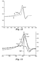
- Figure 9 shows three first-heat nonreversing heat flow plots obtained for the webs of Examples C1, 1 and C6, each web having been subjected to heat treatment at a different temperature - Example C1, about 151 °C (Plot A), Example 1, about 154 °C (Plot B), and Example C6, about 166 °C (Plot C).
- Example C 1 was treated at a temperature too low to accomplish a desired morphological refinement according to the invention, and Plot A shows that because there is a significant crystal-perfection peak T CP having its greatest magnitude at a temperature lower than the Nominal Melting Point.
- Example 1 was treated at an effective temperature, and Plot B shows that the greatest magnitude of the crystal-perfection peak is above the Nominal Melting Point.
- Example C6 was treated at too high a temperature to accomplish a desired morphological reduction (note that a significant crystal-perfection peak has been regenerated at a temperature lower than the Nominal Melting Point; in other words, the heat treatment has caused such a substantial "melting" of the fibers as to regenerate lower-order or imperfect crystal structure (by comparison, such crystal structure was reduced in the Example 1 web by the appropriate heat treatment at 154 °C).
- Figure 10 presents the first-heat (Plot A) and second-heat (Plot B) nonreversing-heat-flow plots for Example 4.
- Table 1 also presents data gathered from Figures 9 and 10 as to the temperature difference (in °C) between the crystal-perfection peaks for the crystallite-characterized phase (T CP1 ) and amorphous-characterized phase (T CP2 ); a zero is entered in the table if the difference between T CP1 and T CP2 is too small to be resolved by the test instrument.
- the treated webs were also studied in a Melting Distortion test conducted by examining the webs under an optical microscope (magnification of about 50 times). Surface fibers not at fiber intersections were examined for any distortion from a circular cross-section.
- the molding capabilities of the webs of Examples 4 and C8 were examined by molding representative samples into a respirator-shaped cup shape using conventional molding conditions but different mold temperatures shown in Table 2 below.
- Two samples of each example were molded using a five-second molding cycle.
- the mold height was 5.7 centimeters and formed a generally oval shape with a minor axis of 11.5 centimeters and a major axis of 13 centimeters. There was a 0.5-centimeter gap between mold sections.
- the height of the molded cup was measured by clamping it to a table top, placing a flat blade on top of the molded cup, and measuring the distance from the table top to the knife blade. A 100-gram weight was then laid on the blade and the height measured again. Table 2 reports the mold temperatures and the height measurements.
- the webs of Example 4 replicated well the mold shape even when molded at a temperature of 155 °C, less than the Nominal Melting Point of the webs. All the molded Example 4 webs except one of those molded at 155 °C and the two molded at 205 °C were essentially at mold height and the others were at least 87% or 83%, respectively, of mold height. (For purposes herein replication is regarded as attaining at least 75% of mold dimensions.) It is also noted that the molded Example 1 webs held their shape well under pressure, while the C8 molded webs essentially collapsed under pressure.
- the webs of Examples 7 and 8 and C9-C11 were prepared by carding oriented crimped nylon 6-6 staple fibers on a Holingsworth random card; the fibers, supplied by Rhodia Technical Fibers, Gerliswilstrasse 19 CH-6021 Emmenbrucke, Germany, were characterized as 2-inch (about 5 centimeter) cut staple 6-denier (16.7 decitex) fiber having a crimp count of three per inch (1.2 per centimeter).
- Unbonded webs of 100 gsm basis weight were prepared and passed on a conveyor through a quenched flow heater as pictured in Figures 4 and 5 and generally as described in Examples 1-6 with further conditions as described in Table 3 below and as follows: heated air was delivered at 1050 meters per minute; the web was quenched by 25 °C ambient air drawn through the web at a rate of about 400 meters per minute over a length along the conveyor of 15 centimeters.
- Example 10 Treatment Temperature (°C) Speed (m/min) Slot Width (cm) Melting observed Web bonded T CP1 - T CP2 C9 245 4.6 3.81 N N 1.4 7 255 4.6 3.81 N Y 8.8 8 257 13.7 3.81 N Y 8.1 9 260 13.7 3.81 N Y 7.0 C11 260 13.7 0.64 Y Y 1.7 C12 260 4.6 3.81 Y Y 0 10 265 13.7 0.64 Y* Y 7.6 C13 265 4.6 3.81 Y Y 5.0 * top surface only Although Example 10 showed some melting on the top surface, fibers deeper within the web were not melted, and these webs were thus regarded as meeting the desired performance characteristics; it is not clear to us why Example C11 did not demonstrate similar effects.
- a commercial polypropylene spunbond web (BBA Spunbond Typar style 3141N, available from BBA Fibcrwcb Americas Industrial Division, Old Hickory, TN) having a nominal basis weight of 50 gsm and comprising oriented polypropylene fibers having an average diameter of 40 micrometers was treated by passing it through a quenched flow heater apparatus as illustrated by the apparatus 100 in Figures 1 , 4 and 5 .
- the web was passed through the apparatus at a rate of 4.6 meters per minute. Air heated to a temperature as given in Table 4 was passed through the slot 109, which was 3.8 centimeters wide and 56 centimeters long, at a rate of 420 meters per minute.
- the gas-withdrawal device 14 applied a negative pressure of 215 mm H 2 O below the web.
- the plates 104 and 111 were as described for Examples 1-6.
- Ambient air at a temperature of about 25 degrees C was drawn through the web at a rate of 360 meters per minute through a distance 120 of 15 centimeters.
- the treated webs were studied in the described Melting Distortion test, and were also subjected to a Rebonding test in which two five-inch-long (12.7-centimeter-long) pieces of a treated web are overlaid on one another and heated and pressed in a calendering operation.
- the pieces are overlaid with their top surfaces (the top of the web as it went through the quenched flow heater) facing one another and with a 5-centimeter-long overlap.
- the overlaid pieces were passed through calender rolls having a surface temperature of 80 degrees C at a rate of 3.9 meters per minute and with a nip pressure of 3.9 kilograms force per centimeter. After calendering, the opposite ends of the webs were grasped and one end was twisted 180 degrees. Bonded webs showed no sign of separation when viewed under a microscope.
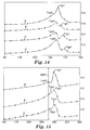
- Plot B shows that after treatment according to the invention a significant bonding phase (T CP2 ) has been generated and the holding-phase peak maximum (T CP1 ) has moved to temperature greater than the Nominal Melting Point (see Figure 13).
- Figure 13 also presents first-heat nonreversing heat flow plots, where Plot A is for Example C15, Plot B is for Example 14, and Plot C is for Example C19.
- Figure 13 reveals that the heating temperature for Comparative Example C14 was too low for useful refinement; treatment in Example 14 produced distinctive and useful bonding and holding phases; and the treatment for Comparative Example C19 was too hot and melted the holding phase.
- a nonwoven fibrous web was prepared from oriented polypropylene 4-denier, 4.76-centimeter crimped staple fibers (Kosa T196 White 060 Staple Fibers, available from Fiber Visions Inc., Covington, GA) using a Hergeth Random card.
- An unbonded web having a basis weight of 100 grams per square centimeter was prepared.
- Samples of the web were then treated with a quenched flow heater apparatus 100 as shown in Figures 4 and 5 . The samples were passed through the treatment apparatus at a rate of 4.6 meters per second. Air heated to a temperature as given in Table 5 was passed through the slot 109, which was 3.8 centimeters wide and 56 centimeters long, at a rate of 420 meters per minute.
- the gas-withdrawal device 14 applied a negative pressure of 215 mm H 2 O below the web.
- the plates 104 and 111 were as described for Examples 1-6.
- Ambient air at a temperature of about 25 plus-or-minus 2 degrees C was drawn through the web at a rate of 360 meters per minute through a distance 120 of 15 centimeters.
- Plot A illustrates that the commercial fibers used in preparing webs of the invention were highly crystalline with too little bonding phase for useful bonding; and further shows that the heating temperature in Example C21 was too low to cause useful refinement.
- Unbonded nonwoven fibrous webs weighing 100 grams per square meter were prepared on a Rando Webber from oriented polyethylene terephthalate 4.7-decitex by 2-inch-long (about 5 cm) crimped staple fibers (Kosa T224 fibers from Fiber Visions Incorporated Covington, Georgia).
- the webs were passed under a quenched flow heater as shown in Figures 4 and 5 at speeds reported in Table 6. Heated air was delivered through a slot 109 at 1050 meters per minute at the temperatures reported in Table 6; the slot width is also reported in Table 6.
- the web was quenched by ambient air (about 25 °C) drawn through the web at 400 meters/minute; the distance 120 was 15 cm.
- Plot A illustrates that the commercial fibers used in preparing webs of the invention were highly crystalline with too little bonding phase for useful bonding; and further shows that the heating temperature in Example C25 was too low to cause useful refinement.
- the totality of tests shows that the treatment for Example 19 developed a useful bonding and holding phase, while the treatment for Comparative Example C27 was too hot and melted the holding phase.
Landscapes
- Engineering & Computer Science (AREA)
- Textile Engineering (AREA)
- Nonwoven Fabrics (AREA)
Applications Claiming Priority (2)
| Application Number | Priority Date | Filing Date | Title |
|---|---|---|---|
| US11/461,201 US9139940B2 (en) | 2006-07-31 | 2006-07-31 | Bonded nonwoven fibrous webs comprising softenable oriented semicrystalline polymeric fibers and apparatus and methods for preparing such webs |
| PCT/US2007/073559 WO2008016770A1 (en) | 2006-07-31 | 2007-07-16 | Bonded nonwoven fibrous webs comprising softenable oriented semicrystalline polymeric fibers and apparatus and methods for preparing such webs |
Publications (2)
| Publication Number | Publication Date |
|---|---|
| EP2047021A1 EP2047021A1 (en) | 2009-04-15 |
| EP2047021B1 true EP2047021B1 (en) | 2013-11-27 |
Family
ID=38645730
Family Applications (1)
| Application Number | Title | Priority Date | Filing Date |
|---|---|---|---|
| EP20070799607 Not-in-force EP2047021B1 (en) | 2006-07-31 | 2007-07-16 | Bonded nonwoven fibrous webs comprising softenable oriented semicrystalline polymeric fibers and apparatus and methods for preparing such webs |
Country Status (7)
| Country | Link |
|---|---|
| US (1) | US9139940B2 (enExample) |
| EP (1) | EP2047021B1 (enExample) |
| JP (1) | JP5508012B2 (enExample) |
| KR (1) | KR101445403B1 (enExample) |
| CN (1) | CN101495691B (enExample) |
| BR (1) | BRPI0714941A2 (enExample) |
| WO (1) | WO2008016770A1 (enExample) |
Cited By (1)
| Publication number | Priority date | Publication date | Assignee | Title |
|---|---|---|---|---|
| TWI726706B (zh) * | 2020-04-30 | 2021-05-01 | 新麗企業股份有限公司 | 可調密度之纖維結構體的製造裝置及方法 |
Families Citing this family (111)
| Publication number | Priority date | Publication date | Assignee | Title |
|---|---|---|---|---|
| US7807591B2 (en) | 2006-07-31 | 2010-10-05 | 3M Innovative Properties Company | Fibrous web comprising microfibers dispersed among bonded meltspun fibers |
| US9770058B2 (en) | 2006-07-17 | 2017-09-26 | 3M Innovative Properties Company | Flat-fold respirator with monocomponent filtration/stiffening monolayer |
| US7858163B2 (en) * | 2006-07-31 | 2010-12-28 | 3M Innovative Properties Company | Molded monocomponent monolayer respirator with bimodal monolayer monocomponent media |
| US7947142B2 (en) | 2006-07-31 | 2011-05-24 | 3M Innovative Properties Company | Pleated filter with monolayer monocomponent meltspun media |
| US7754041B2 (en) * | 2006-07-31 | 2010-07-13 | 3M Innovative Properties Company | Pleated filter with bimodal monolayer monocomponent media |
| US7989372B2 (en) * | 2007-06-22 | 2011-08-02 | 3M Innovative Properties Company | Molded respirator comprising meltblown fiber web with staple fibers |
| US7989371B2 (en) * | 2007-06-22 | 2011-08-02 | 3M Innovative Properties Company | Meltblown fiber web with staple fibers |
| US20080315454A1 (en) * | 2007-06-22 | 2008-12-25 | 3M Innovative Properties Company | Method of making meltblown fiber web with staple fibers |
| AU2008289195B2 (en) * | 2007-08-17 | 2012-05-24 | Fiberweb, Inc. | Area bonded nonwoven fabric from single polymer system |
| EP2231912B1 (en) * | 2007-12-28 | 2014-10-22 | 3M Innovative Properties Company | Composite nonwoven fibrous webs and methods of making and using the same |
| CN101952210B (zh) | 2007-12-31 | 2013-05-29 | 3M创新有限公司 | 流体过滤制品及其制造和使用方法 |
| EP2235245B1 (en) * | 2007-12-31 | 2015-12-02 | 3M Innovative Properties Company | Composite non-woven fibrous webs having continuous particulate phase and methods of making and using the same |
| JP5670887B2 (ja) | 2008-06-12 | 2015-02-18 | スリーエム イノベイティブ プロパティズ カンパニー | 生体適合性親水性組成物 |
| JP5485988B2 (ja) * | 2008-06-12 | 2014-05-07 | スリーエム イノベイティブ プロパティズ カンパニー | メルトブローン微細繊維及び製造方法 |
| JP5767113B2 (ja) | 2008-12-23 | 2015-08-19 | スリーエム イノベイティブ プロパティズ カンパニー | パターン付きスパンボンド繊維ウェブ及びこれを作製する方法 |
| DK2384375T3 (en) | 2009-01-16 | 2017-10-16 | Zeus Ind Products Inc | ELECTROSPINING PTFE WITH HIGH-VISUAL MATERIALS |
| US20130268062A1 (en) | 2012-04-05 | 2013-10-10 | Zeus Industrial Products, Inc. | Composite prosthetic devices |
| BRPI1006777A2 (pt) | 2009-03-31 | 2019-09-24 | 3M Innovative Properties Co | "mantas, artigo, lençol cirúrgico, avental cirúrgico, invólucro de esterilização, material de contato para ferimentos e métodos para fabricação de uma manta" |
| US8162153B2 (en) * | 2009-07-02 | 2012-04-24 | 3M Innovative Properties Company | High loft spunbonded web |
| WO2011028661A2 (en) | 2009-09-01 | 2011-03-10 | 3M Innovative Properties Company | Apparatus, system, and method for forming nanofibers and nanofiber webs |
| EP2513365A4 (en) | 2009-12-17 | 2013-09-18 | 3M Innovative Properties Co | DIMENSION-STABLE FIBER-NETS, MELT-BLOWN FIBER-FIBERS, AND METHOD FOR THEIR PRODUCTION AND USE |
| CN105274733B (zh) * | 2009-12-17 | 2018-11-20 | 3M创新有限公司 | 尺寸稳定的非织造纤维幅材及其制造和使用方法 |
| WO2011106205A2 (en) | 2010-02-23 | 2011-09-01 | 3M Innovative Properties Company | Dimensionally stable nonwoven fibrous webs and methods of making and using the same |
| JP5819939B2 (ja) | 2010-04-22 | 2015-11-24 | スリーエム イノベイティブ プロパティズ カンパニー | 化学的に活性な微粒子を含有する不織布ナノ繊維ウェブ並びにそれを作製及び使用する方法 |
| WO2011133396A1 (en) | 2010-04-22 | 2011-10-27 | 3M Innovative Properties Company | Nonwoven fibrous webs containing chemically active particulates and methods of making and using same |
| KR20130041928A (ko) | 2010-07-07 | 2013-04-25 | 쓰리엠 이노베이티브 프로퍼티즈 컴파니 | 패턴화된 에어 레이드 부직포 섬유질 웨브 및 그 제조 및 사용 방법 |
| TW201221714A (en) | 2010-10-14 | 2012-06-01 | 3M Innovative Properties Co | Dimensionally stable nonwoven fibrous webs and methods of making and using the same |
| US8744251B2 (en) | 2010-11-17 | 2014-06-03 | 3M Innovative Properties Company | Apparatus and methods for delivering a heated fluid |
| US9802187B2 (en) | 2011-06-30 | 2017-10-31 | 3M Innovative Properties Company | Non-woven electret fibrous webs and methods of making same |
| EP2565304A1 (de) * | 2011-09-02 | 2013-03-06 | Aurotec GmbH | Extrusionsverfahren und -vorrichtung |
| CN102747537B (zh) * | 2011-12-20 | 2015-07-22 | 金红叶纸业集团有限公司 | 一种复合无纺布固结设备及工艺 |
| EP2798107B1 (en) | 2011-12-30 | 2018-01-24 | 3M Innovative Properties Company | Methods and apparatus for producing nonwoven fibrous webs |
| CN104220661B (zh) * | 2011-12-30 | 2019-04-12 | 3M创新有限公司 | 用于制备非织造纤维网的设备和方法 |
| US9821276B2 (en) | 2012-04-24 | 2017-11-21 | 3M Innovative Properties Company | Nonwoven article grafted with copolymer |
| CA2887807A1 (en) | 2012-10-12 | 2014-04-17 | 3M Innovative Properties Company | Multi-layer articles |
| BR112015015420A2 (pt) | 2012-12-28 | 2017-07-11 | 3M Innovative Properties Co | mantas de eletreto com aditivos acentuadores de carga |
| US9314995B2 (en) | 2013-03-15 | 2016-04-19 | National Nonwovens Inc. | Composites comprising nonwoven structures and foam |
| US9314993B2 (en) * | 2013-03-15 | 2016-04-19 | National Nonwovens Inc. | Composites and articles made from nonwoven structures |
| CA2909670A1 (en) | 2013-04-19 | 2014-10-23 | 3M Innovative Properties Company | Electret webs with charge-enhancing additives |
| US9174159B2 (en) | 2013-08-16 | 2015-11-03 | 3M Innovative Properties Company | Framed pleated air filter with upstream bridging filaments |
| US9278301B2 (en) | 2013-08-16 | 2016-03-08 | 3M Innovative Properties Company | Nestable framed pleated air filter and method of making |
| US9982128B2 (en) | 2013-09-30 | 2018-05-29 | 3M Innovative Properties Company | Fibers, wipes, and methods |
| CN105579637B (zh) | 2013-09-30 | 2018-04-10 | 3M创新有限公司 | 具有设置于其上的环氧化脂肪酸酯的纤维和擦拭物以及方法 |
| US20160235057A1 (en) | 2013-09-30 | 2016-08-18 | 3M Innovative Properties Company | Compositions, Wipes, and Methods |
| JP6584408B2 (ja) | 2013-12-13 | 2019-10-02 | スリーエム イノベイティブ プロパティズ カンパニー | オンデマンド接着用マイクロカプセルを含む物品及びその製造方法 |
| US10961644B2 (en) | 2014-01-29 | 2021-03-30 | Biax-Fiberfilm Corporation | High loft, nonwoven web exhibiting excellent recovery |
| US10704173B2 (en) | 2014-01-29 | 2020-07-07 | Biax-Fiberfilm Corporation | Process for forming a high loft, nonwoven web exhibiting excellent recovery |
| CN104018294B (zh) * | 2014-04-10 | 2016-06-22 | 中国科学院宁波材料技术与工程研究所 | 一种聚乳酸纳米纤维膜及其制备方法 |
| CN106661786B (zh) | 2014-06-23 | 2019-05-21 | 3M创新有限公司 | 包含电荷加强添加剂的驻极体料片 |
| PL3186425T3 (pl) | 2014-08-26 | 2020-05-18 | 3M Innovative Properties Company | Siatka z włókniny typu spunbonded zawierająca włókna poli(kwasumlekowego) |
| WO2016119080A1 (en) | 2015-01-29 | 2016-08-04 | 3M Innovative Properties Company | Conformable pleated air filter with bridging filaments |
| KR20180021180A (ko) | 2015-06-30 | 2018-02-28 | 쓰리엠 이노베이티브 프로퍼티즈 캄파니 | 접착제 에지-밀봉된 단부를 갖는 필터 매체를 포함하는 필터 카트리지, 및 제조 및 사용 방법 |
| MX2018000117A (es) | 2015-07-07 | 2018-03-22 | 3M Innovative Properties Co | Tramas de electreto con aditivos mejoradores de la carga. |
| US11053373B2 (en) | 2015-07-07 | 2021-07-06 | 3M Innovative Properties Company | Polymeric matrices with ionic additives |
| WO2017007677A1 (en) | 2015-07-07 | 2017-01-12 | 3M Innovative Properties Company | Substituted benzotriazole phenolate salts and antioxidant compositions formed therefrom |
| EP3319947B1 (en) | 2015-07-07 | 2022-05-04 | 3M Innovative Properties Company | Substituted benzotriazole phenols |
| KR20180073705A (ko) | 2015-11-19 | 2018-07-02 | 쓰리엠 이노베이티브 프로퍼티즈 캄파니 | 밀착 검사 디바이스를 구비한 필터 카트리지 홀더 |
| EP3419736A4 (en) | 2016-02-26 | 2019-10-23 | 3M Innovative Properties Company | AIR CONDITIONING FILTER AND METHOD OF MANUFACTURING THEREOF |
| WO2017213926A1 (en) | 2016-06-06 | 2017-12-14 | 3M Innovative Properties Company | Channel-framed, pleated air filter with bridging filaments |
| CA3032923A1 (en) | 2016-08-05 | 2018-02-08 | 3M Innovative Properties Company | Air filter with passivated filter life indicator |
| JP2019531880A (ja) | 2016-08-26 | 2019-11-07 | スリーエム イノベイティブ プロパティズ カンパニー | 縁部ダムを有するプリーツフィルタメディアを備えるプリーツフィルタエレメント並びにこれを製造及び使用する方法 |
| EP3515662B1 (en) | 2016-09-26 | 2024-01-10 | 3M Innovative Properties Company | Nonwoven abrasive articles having electrostatically-oriented abrasive particles and methods of making same |
| WO2018090279A1 (en) | 2016-11-17 | 2018-05-24 | 3M Innovative Properties Company | Air filter with visual filter life indicator zone and sorbent-loaded visual reference zone |
| US20190336896A1 (en) | 2017-01-05 | 2019-11-07 | 3M Innovative Properties Company | Electret webs with charge-enhancing additives |
| CN110462906B (zh) | 2017-03-31 | 2022-08-19 | 可隆工业株式会社 | 离子交换膜、其制造方法以及包括其的能量存储装置 |
| WO2018182191A1 (ko) | 2017-03-31 | 2018-10-04 | 코오롱인더스트리 주식회사 | 이온 교환막, 이의 제조 방법 및 이를 포함하는 에너지 저장 장치 |
| CA3060405C (en) | 2017-04-18 | 2020-06-16 | 3M Innovative Properties Company | Air filter media with post-pleat-deposited sorbent particles |
| KR102646045B1 (ko) | 2017-08-25 | 2024-03-11 | 쓰리엠 이노베이티브 프로퍼티즈 컴파니 | 무손상 제거가 가능한 접착 물품 |
| TWI795430B (zh) | 2017-08-25 | 2023-03-11 | 美商3M新設資產公司 | 容許無損傷移除的黏著劑物品 |
| EP3682048A4 (en) | 2017-09-15 | 2021-09-01 | 3M Innovative Properties Company | FIBER FIBER WEB AND METHOD FOR IT |
| WO2019079695A1 (en) | 2017-10-19 | 2019-04-25 | 3M Innovative Properties Company | ACOUSTIC ARTICLE AND ASSOCIATED METHODS |
| EP3723984A4 (en) | 2017-12-15 | 2021-08-18 | 3M Innovative Properties Company | TEXTURED PRINTABLE FLEECE MEDIA |
| EP3727749B1 (en) | 2017-12-20 | 2025-08-06 | 3M Innovative Properties Company | Abrasive articles including a saturant and an anti-loading size layer |
| WO2020026149A1 (en) | 2018-08-03 | 2020-02-06 | 3M Innovative Properties Company | Pleated air filter with bridging filaments and continuous-contact filaments |
| US11839845B2 (en) | 2018-08-03 | 2023-12-12 | 3M Innovative Properties Company | Air-filter media comprising a relofted spunbonded web, and methods of making and using |
| CN112888492A (zh) | 2018-08-03 | 2021-06-01 | 3M创新有限公司 | 包括再蓬松纺粘幅材的空气过滤介质以及制备和使用方法 |
| US12053733B2 (en) | 2018-08-03 | 2024-08-06 | 3M Innovative Properties Company | Pleated air filter with reinforcing filaments comprising locally-thinned bending zones |
| WO2020079525A1 (en) | 2018-10-16 | 2020-04-23 | 3M Innovative Properties Company | Flame-retardant non-woven fibrous webs |
| EP3867436A1 (en) | 2018-10-16 | 2021-08-25 | 3M Innovative Properties Company | Flame-retardant non-woven fibrous webs |
| WO2020107421A1 (en) * | 2018-11-30 | 2020-06-04 | The Procter & Gamble Company | Methods for through-fluid bonding nonwoven webs |
| CN113166994B (zh) | 2018-11-30 | 2022-09-30 | 宝洁公司 | 用于制备通流粘结的非织造纤维网的方法 |
| CN113166988B (zh) | 2018-11-30 | 2023-04-07 | 宝洁公司 | 形成柔软且蓬松的非织造纤维网的方法 |
| US12109520B2 (en) | 2019-01-21 | 2024-10-08 | 3M Innovative Properties Company | Multi-layer, biodegradable composites for air filtration |
| SE543542C2 (en) | 2019-02-19 | 2021-03-23 | Swedish Match North Europe Ab | Arrangement and method for manufacturing of a web of packaging material for an oral pouched snuff product |
| KR102237734B1 (ko) | 2019-02-27 | 2021-04-07 | 성인석 | 다단계 해수여과 및 살균 정수장치 |
| CN113710845A (zh) | 2019-04-25 | 2021-11-26 | 3M创新有限公司 | 声学制品及其方法 |
| JP2022538254A (ja) | 2019-06-26 | 2022-09-01 | スリーエム イノベイティブ プロパティズ カンパニー | 不織繊維ウェブの製造方法、不織繊維ウェブ、及び多成分繊維 |
| CN114555691B (zh) | 2019-10-16 | 2023-11-28 | 3M创新有限公司 | 取代的苯并咪唑熔体添加剂 |
| US20220380574A1 (en) | 2019-10-16 | 2022-12-01 | 3M Innovative Properties Company | Dual-function melt additives |
| CN114765996B (zh) | 2019-12-03 | 2023-06-02 | 3M创新有限公司 | 硫醇盐熔体添加剂 |
| CN115038829B (zh) | 2019-12-03 | 2023-07-28 | 3M创新有限公司 | 芳族杂环熔体添加剂 |
| US11982031B2 (en) | 2020-01-27 | 2024-05-14 | 3M Innovative Properties Company | Substituted thiol melt additives |
| EP4097284B1 (en) | 2020-01-27 | 2024-05-29 | 3M Innovative Properties Company | Substituted thiolate salt melt additives |
| US12409401B2 (en) | 2020-07-08 | 2025-09-09 | 3M Innovative Properties Company | Pleated filtration assembly comprising spunbonded prefilter |
| CN116033954A (zh) | 2020-08-11 | 2023-04-28 | 3M创新有限公司 | 具有苯甲酸盐电荷增强添加剂的驻极体料片 |
| CN116348190A (zh) | 2020-08-11 | 2023-06-27 | 3M创新有限公司 | 具有羧酸或羧酸盐电荷增强添加剂的驻极体料片 |
| CN116670753A (zh) | 2020-09-11 | 2023-08-29 | 3M创新有限公司 | 吸声填料和相关的声学制品 |
| WO2022053977A1 (en) | 2020-09-11 | 2022-03-17 | 3M Innovative Properties Company | Acoustic absorbing filler and related acoustic article |
| CA3198869A1 (en) | 2020-10-15 | 2022-04-21 | 3M Innovative Properties Company | Adhesive assemblies permitting enhanced weight bearing performance with damage free removal |
| EP4233043A1 (en) | 2020-10-23 | 2023-08-30 | 3M Innovative Properties Company | Acoustic articles and assemblies |
| WO2022136968A1 (en) | 2020-12-23 | 2022-06-30 | 3M Innovative Properties Company | Method of separating a virus from a composition using copolymer-grafted nonwoven substrates |
| WO2022172222A1 (en) | 2021-02-12 | 2022-08-18 | 3M Innovative Properties Company | Sample collection device and system |
| EP4312796A1 (en) | 2021-04-02 | 2024-02-07 | 3M Innovative Properties Company | Sample collection device and method |
| WO2022214884A1 (en) | 2021-04-06 | 2022-10-13 | 3M Innovative Properties Company | Sample collection devices, systems, and methods |
| JP2024519891A (ja) | 2021-05-21 | 2024-05-21 | スリーエム イノベイティブ プロパティズ カンパニー | サンプル収集デバイス及びシステム |
| EP4340737A1 (en) | 2021-05-21 | 2024-03-27 | 3M Innovative Properties Company | Pop-up sample collection device and system |
| KR20230165860A (ko) | 2021-06-08 | 2023-12-05 | 자빌 인코퍼레이티드 | 비결정질 열가소성 적층 제조 물품 및 이의 제조 방법 |
| WO2023042016A1 (en) | 2021-09-15 | 2023-03-23 | 3M Innovative Properties Company | Acoustic articles and methods of making the same |
| US12479143B2 (en) | 2021-12-20 | 2025-11-25 | Lear Corporation | System and method of making a mesh cushion |
| US12454111B2 (en) | 2022-05-11 | 2025-10-28 | Lear Corporation | Tool to manufacture a cushion |
| WO2025202974A1 (en) | 2024-03-29 | 2025-10-02 | 3M Innovative Properties Company | Respirators, respirator materials and methods of manufacturing the same |
Family Cites Families (41)
| Publication number | Priority date | Publication date | Assignee | Title |
|---|---|---|---|---|
| DE1950669C3 (de) | 1969-10-08 | 1982-05-13 | Metallgesellschaft Ag, 6000 Frankfurt | Verfahren zur Vliesherstellung |
| US3715251A (en) | 1969-10-09 | 1973-02-06 | Exxon Research Engineering Co | Laminated non-woven sheet |
| US3971373A (en) | 1974-01-21 | 1976-07-27 | Minnesota Mining And Manufacturing Company | Particle-loaded microfiber sheet product and respirators made therefrom |
| CA1073648A (en) | 1976-08-02 | 1980-03-18 | Edward R. Hauser | Web of blended microfibers and crimped bulking fibers |
| US4405297A (en) | 1980-05-05 | 1983-09-20 | Kimberly-Clark Corporation | Apparatus for forming nonwoven webs |
| US4340563A (en) | 1980-05-05 | 1982-07-20 | Kimberly-Clark Corporation | Method for forming nonwoven webs |
| US4364156A (en) | 1981-01-23 | 1982-12-21 | Milliken Research Corporation | Apparatus for heated pressurized fluid stream treatment of substrate material |
| US5532050A (en) | 1986-06-30 | 1996-07-02 | Wm. T. Burnett & Co., Inc. | Densified thermo-bonded synthetic fiber batting |
| DE3713862A1 (de) | 1987-04-25 | 1988-11-10 | Reifenhaeuser Masch | Verfahren und spinnvliesanlage zur herstellung eines spinnvlieses aus synthetischem endlosfilament |
| US4813948A (en) | 1987-09-01 | 1989-03-21 | Minnesota Mining And Manufacturing Company | Microwebs and nonwoven materials containing microwebs |
| US4931355A (en) | 1988-03-18 | 1990-06-05 | Radwanski Fred R | Nonwoven fibrous hydraulically entangled non-elastic coform material and method of formation thereof |
| US5079080A (en) | 1989-05-26 | 1992-01-07 | Bix Fiberfilm Corporation | Process for forming a superabsorbent composite web from fiberforming thermoplastic polymer and supersorbing polymer and products produced thereby |
| US5685757A (en) | 1989-06-20 | 1997-11-11 | Corovin Gmbh | Fibrous spun-bonded non-woven composite |
| CA2105026C (en) | 1993-04-29 | 2003-12-16 | Henry Louis Griesbach Iii | Shaped nonwoven fabric and method for making the same |
| EP0714463B1 (en) | 1993-08-17 | 1999-03-10 | Minnesota Mining And Manufacturing Company | Method of charging electret filter media |
| CA2129496A1 (en) | 1994-04-12 | 1995-10-13 | Mary Lou Delucia | Strength improved single polymer conjugate fiber webs |
| US5707468A (en) | 1994-12-22 | 1998-01-13 | Kimberly-Clark Worldwide, Inc. | Compaction-free method of increasing the integrity of a nonwoven web |
| DE19501125C2 (de) | 1995-01-17 | 1997-10-16 | Reifenhaeuser Masch | Verfahren zur Herstellung einer Vliesbahn aus thermoplastischen Polymerfilamenten |
| US5591335A (en) | 1995-05-02 | 1997-01-07 | Memtec America Corporation | Filter cartridges having nonwoven melt blown filtration media with integral co-located support and filtration |
| US5817584A (en) * | 1995-12-22 | 1998-10-06 | Kimberly-Clark Worldwide, Inc. | High efficiency breathing mask fabrics |
| US6315806B1 (en) | 1997-09-23 | 2001-11-13 | Leonard Torobin | Method and apparatus for producing high efficiency fibrous media incorporating discontinuous sub-micron diameter fibers, and web media formed thereby |
| US6410138B2 (en) | 1997-09-30 | 2002-06-25 | Kimberly-Clark Worldwide, Inc. | Crimped multicomponent filaments and spunbond webs made therefrom |
| US5958322A (en) * | 1998-03-24 | 1999-09-28 | 3M Innovation Properties Company | Method for making dimensionally stable nonwoven fibrous webs |
| US6019152A (en) | 1998-07-29 | 2000-02-01 | Kimberly-Clark Worldwide, Inc. | Apparatus for heating nonwoven webs |
| US6394090B1 (en) * | 1999-02-17 | 2002-05-28 | 3M Innovative Properties Company | Flat-folded personal respiratory protection devices and processes for preparing same |
| US6502615B1 (en) | 1999-12-22 | 2003-01-07 | Nordson Corporation | Apparatus for making an absorbent composite product |
| US6607624B2 (en) | 2000-11-20 | 2003-08-19 | 3M Innovative Properties Company | Fiber-forming process |
| AU2002243282B2 (en) | 2000-11-20 | 2006-07-06 | 3M Innovative Properties Company | Fiber-forming process |
| US6667254B1 (en) * | 2000-11-20 | 2003-12-23 | 3M Innovative Properties Company | Fibrous nonwoven webs |
| US6736916B2 (en) | 2000-12-20 | 2004-05-18 | Kimberly-Clark Worldwide, Inc. | Hydraulically arranged nonwoven webs and method of making same |
| JP2003020555A (ja) | 2001-07-11 | 2003-01-24 | Toray Ind Inc | 積層不織布の製造方法 |
| WO2003014451A1 (en) | 2001-08-07 | 2003-02-20 | The Procter & Gamble Company | Fibers and webs capable of high speed solid state deformation |
| US20030114066A1 (en) | 2001-12-13 | 2003-06-19 | Clark Darryl Franklin | Uniform distribution of absorbents in a thermoplastic web |
| US7258758B2 (en) | 2001-12-21 | 2007-08-21 | Kimberly-Clark Worldwide, Inc. | Strong high loft low density nonwoven webs and laminates thereof |
| US6916752B2 (en) * | 2002-05-20 | 2005-07-12 | 3M Innovative Properties Company | Bondable, oriented, nonwoven fibrous webs and methods for making them |
| US7677248B2 (en) | 2002-06-05 | 2010-03-16 | Louis M. Gerson Co., Inc. | Stiffened filter mask |
| US6827765B2 (en) | 2003-01-10 | 2004-12-07 | Macronix International Co., Ltd. | Scrubber for reducing siliciferous byproducts |
| DE10336380B4 (de) | 2003-08-06 | 2005-08-25 | Carl Freudenberg Kg | Ultradünner, poröser und mechanisch stabiler Vliesstoff und dessen Verwendung |
| US6858297B1 (en) | 2004-04-05 | 2005-02-22 | 3M Innovative Properties Company | Aligned fiber web |
| JP4932194B2 (ja) | 2005-08-26 | 2012-05-16 | 日本バイリーン株式会社 | エアフィルタ用濾材及びエアフィルタユニット |
| DE102006014236A1 (de) | 2006-03-28 | 2007-10-04 | Irema-Filter Gmbh | Plissierbares Vliesmaterial und Verfahren und Vorrichtung zur Herstellung derselben |
-
2006
- 2006-07-31 US US11/461,201 patent/US9139940B2/en active Active
-
2007
- 2007-07-16 KR KR1020097001975A patent/KR101445403B1/ko not_active Expired - Fee Related
- 2007-07-16 WO PCT/US2007/073559 patent/WO2008016770A1/en not_active Ceased
- 2007-07-16 JP JP2009522918A patent/JP5508012B2/ja active Active
- 2007-07-16 CN CN2007800286327A patent/CN101495691B/zh not_active Expired - Fee Related
- 2007-07-16 EP EP20070799607 patent/EP2047021B1/en not_active Not-in-force
- 2007-07-16 BR BRPI0714941-7A patent/BRPI0714941A2/pt not_active Application Discontinuation
Cited By (1)
| Publication number | Priority date | Publication date | Assignee | Title |
|---|---|---|---|---|
| TWI726706B (zh) * | 2020-04-30 | 2021-05-01 | 新麗企業股份有限公司 | 可調密度之纖維結構體的製造裝置及方法 |
Also Published As
| Publication number | Publication date |
|---|---|
| US20080038976A1 (en) | 2008-02-14 |
| EP2047021A1 (en) | 2009-04-15 |
| KR101445403B1 (ko) | 2014-09-26 |
| CN101495691B (zh) | 2011-12-14 |
| US9139940B2 (en) | 2015-09-22 |
| JP2009545680A (ja) | 2009-12-24 |
| BRPI0714941A2 (pt) | 2013-03-19 |
| JP5508012B2 (ja) | 2014-05-28 |
| WO2008016770A1 (en) | 2008-02-07 |
| CN101495691A (zh) | 2009-07-29 |
| KR20090035561A (ko) | 2009-04-09 |
Similar Documents
| Publication | Publication Date | Title |
|---|---|---|
| EP2047021B1 (en) | Bonded nonwoven fibrous webs comprising softenable oriented semicrystalline polymeric fibers and apparatus and methods for preparing such webs | |
| US8591683B2 (en) | Method of manufacturing a fibrous web comprising microfibers dispersed among bonded meltspun fibers | |
| EP2054135B1 (en) | Pleated filter with monolayer monocomponent meltspun media | |
| KR101184871B1 (ko) | 부직 탄성 섬유 웹 및 이의 제조 방법 | |
| EP2449159B1 (en) | High loft spunbonded web | |
| EP2102401B1 (en) | Method for making dimensionally stable bonded nonwoven fibrous webs | |
| US7754041B2 (en) | Pleated filter with bimodal monolayer monocomponent media | |
| JP2825514B2 (ja) | 配向された溶融吹付繊維、その製造方法およびそのウェブ | |
| KR20060136383A (ko) | 부직 탄성 섬유 웹 및 이의 제조 방법 | |
| KR20090040308A (ko) | 성형된 1성분 단층 호흡기 | |
| WO2003048442A1 (en) | Spunbound nonwoven fabric | |
| DE112019007855T5 (de) | Vliesbahn mit erhöhter cd-festigkeit | |
| TW202538124A (zh) | 不織布及其製造方法以及積層不織布 | |
| JPH042850A (ja) | ポリブチレンテレフタレート系ポリエステル繊維ウエブの製造方法 |
Legal Events
| Date | Code | Title | Description |
|---|---|---|---|
| PUAI | Public reference made under article 153(3) epc to a published international application that has entered the european phase |
Free format text: ORIGINAL CODE: 0009012 |
|
| 17P | Request for examination filed |
Effective date: 20090217 |
|
| AK | Designated contracting states |
Kind code of ref document: A1 Designated state(s): AT BE BG CH CY CZ DE DK EE ES FI FR GB GR HU IE IS IT LI LT LU LV MC MT NL PL PT RO SE SI SK TR |
|
| AX | Request for extension of the european patent |
Extension state: AL BA HR MK RS |
|
| 17Q | First examination report despatched |
Effective date: 20090605 |
|
| DAX | Request for extension of the european patent (deleted) | ||
| GRAP | Despatch of communication of intention to grant a patent |
Free format text: ORIGINAL CODE: EPIDOSNIGR1 |
|
| INTG | Intention to grant announced |
Effective date: 20130701 |
|
| GRAS | Grant fee paid |
Free format text: ORIGINAL CODE: EPIDOSNIGR3 |
|
| GRAA | (expected) grant |
Free format text: ORIGINAL CODE: 0009210 |
|
| AK | Designated contracting states |
Kind code of ref document: B1 Designated state(s): AT BE BG CH CY CZ DE DK EE ES FI FR GB GR HU IE IS IT LI LT LU LV MC MT NL PL PT RO SE SI SK TR |
|
| REG | Reference to a national code |
Ref country code: GB Ref legal event code: FG4D |
|
| REG | Reference to a national code |
Ref country code: CH Ref legal event code: EP |
|
| REG | Reference to a national code |
Ref country code: AT Ref legal event code: REF Ref document number: 642779 Country of ref document: AT Kind code of ref document: T Effective date: 20131215 |
|
| REG | Reference to a national code |
Ref country code: IE Ref legal event code: FG4D |
|
| REG | Reference to a national code |
Ref country code: DE Ref legal event code: R096 Ref document number: 602007034038 Country of ref document: DE Effective date: 20140123 |
|
| REG | Reference to a national code |
Ref country code: NL Ref legal event code: VDEP Effective date: 20131127 |
|
| REG | Reference to a national code |
Ref country code: AT Ref legal event code: MK05 Ref document number: 642779 Country of ref document: AT Kind code of ref document: T Effective date: 20131127 |
|
| REG | Reference to a national code |
Ref country code: LT Ref legal event code: MG4D |
|
| PG25 | Lapsed in a contracting state [announced via postgrant information from national office to epo] |
Ref country code: IS Free format text: LAPSE BECAUSE OF FAILURE TO SUBMIT A TRANSLATION OF THE DESCRIPTION OR TO PAY THE FEE WITHIN THE PRESCRIBED TIME-LIMIT Effective date: 20140327 Ref country code: LT Free format text: LAPSE BECAUSE OF FAILURE TO SUBMIT A TRANSLATION OF THE DESCRIPTION OR TO PAY THE FEE WITHIN THE PRESCRIBED TIME-LIMIT Effective date: 20131127 Ref country code: NL Free format text: LAPSE BECAUSE OF FAILURE TO SUBMIT A TRANSLATION OF THE DESCRIPTION OR TO PAY THE FEE WITHIN THE PRESCRIBED TIME-LIMIT Effective date: 20131127 Ref country code: FI Free format text: LAPSE BECAUSE OF FAILURE TO SUBMIT A TRANSLATION OF THE DESCRIPTION OR TO PAY THE FEE WITHIN THE PRESCRIBED TIME-LIMIT Effective date: 20131127 Ref country code: SE Free format text: LAPSE BECAUSE OF FAILURE TO SUBMIT A TRANSLATION OF THE DESCRIPTION OR TO PAY THE FEE WITHIN THE PRESCRIBED TIME-LIMIT Effective date: 20131127 |
|
| PG25 | Lapsed in a contracting state [announced via postgrant information from national office to epo] |
Ref country code: LV Free format text: LAPSE BECAUSE OF FAILURE TO SUBMIT A TRANSLATION OF THE DESCRIPTION OR TO PAY THE FEE WITHIN THE PRESCRIBED TIME-LIMIT Effective date: 20131127 Ref country code: AT Free format text: LAPSE BECAUSE OF FAILURE TO SUBMIT A TRANSLATION OF THE DESCRIPTION OR TO PAY THE FEE WITHIN THE PRESCRIBED TIME-LIMIT Effective date: 20131127 Ref country code: CY Free format text: LAPSE BECAUSE OF FAILURE TO SUBMIT A TRANSLATION OF THE DESCRIPTION OR TO PAY THE FEE WITHIN THE PRESCRIBED TIME-LIMIT Effective date: 20131127 Ref country code: BE Free format text: LAPSE BECAUSE OF FAILURE TO SUBMIT A TRANSLATION OF THE DESCRIPTION OR TO PAY THE FEE WITHIN THE PRESCRIBED TIME-LIMIT Effective date: 20131127 Ref country code: ES Free format text: LAPSE BECAUSE OF FAILURE TO SUBMIT A TRANSLATION OF THE DESCRIPTION OR TO PAY THE FEE WITHIN THE PRESCRIBED TIME-LIMIT Effective date: 20131127 |
|
| PG25 | Lapsed in a contracting state [announced via postgrant information from national office to epo] |
Ref country code: PT Free format text: LAPSE BECAUSE OF FAILURE TO SUBMIT A TRANSLATION OF THE DESCRIPTION OR TO PAY THE FEE WITHIN THE PRESCRIBED TIME-LIMIT Effective date: 20140327 |
|
| PG25 | Lapsed in a contracting state [announced via postgrant information from national office to epo] |
Ref country code: EE Free format text: LAPSE BECAUSE OF FAILURE TO SUBMIT A TRANSLATION OF THE DESCRIPTION OR TO PAY THE FEE WITHIN THE PRESCRIBED TIME-LIMIT Effective date: 20131127 |
|
| REG | Reference to a national code |
Ref country code: DE Ref legal event code: R097 Ref document number: 602007034038 Country of ref document: DE |
|
| PG25 | Lapsed in a contracting state [announced via postgrant information from national office to epo] |
Ref country code: SK Free format text: LAPSE BECAUSE OF FAILURE TO SUBMIT A TRANSLATION OF THE DESCRIPTION OR TO PAY THE FEE WITHIN THE PRESCRIBED TIME-LIMIT Effective date: 20131127 Ref country code: PL Free format text: LAPSE BECAUSE OF FAILURE TO SUBMIT A TRANSLATION OF THE DESCRIPTION OR TO PAY THE FEE WITHIN THE PRESCRIBED TIME-LIMIT Effective date: 20131127 Ref country code: CZ Free format text: LAPSE BECAUSE OF FAILURE TO SUBMIT A TRANSLATION OF THE DESCRIPTION OR TO PAY THE FEE WITHIN THE PRESCRIBED TIME-LIMIT Effective date: 20131127 Ref country code: RO Free format text: LAPSE BECAUSE OF FAILURE TO SUBMIT A TRANSLATION OF THE DESCRIPTION OR TO PAY THE FEE WITHIN THE PRESCRIBED TIME-LIMIT Effective date: 20131127 |
|
| PG25 | Lapsed in a contracting state [announced via postgrant information from national office to epo] |
Ref country code: DK Free format text: LAPSE BECAUSE OF FAILURE TO SUBMIT A TRANSLATION OF THE DESCRIPTION OR TO PAY THE FEE WITHIN THE PRESCRIBED TIME-LIMIT Effective date: 20131127 |
|
| PLBE | No opposition filed within time limit |
Free format text: ORIGINAL CODE: 0009261 |
|
| STAA | Information on the status of an ep patent application or granted ep patent |
Free format text: STATUS: NO OPPOSITION FILED WITHIN TIME LIMIT |
|
| 26N | No opposition filed |
Effective date: 20140828 |
|
| REG | Reference to a national code |
Ref country code: DE Ref legal event code: R097 Ref document number: 602007034038 Country of ref document: DE Effective date: 20140828 |
|
| PG25 | Lapsed in a contracting state [announced via postgrant information from national office to epo] |
Ref country code: SI Free format text: LAPSE BECAUSE OF FAILURE TO SUBMIT A TRANSLATION OF THE DESCRIPTION OR TO PAY THE FEE WITHIN THE PRESCRIBED TIME-LIMIT Effective date: 20131127 Ref country code: LU Free format text: LAPSE BECAUSE OF FAILURE TO SUBMIT A TRANSLATION OF THE DESCRIPTION OR TO PAY THE FEE WITHIN THE PRESCRIBED TIME-LIMIT Effective date: 20140716 |
|
| REG | Reference to a national code |
Ref country code: CH Ref legal event code: PL |
|
| GBPC | Gb: european patent ceased through non-payment of renewal fee |
Effective date: 20140716 |
|
| REG | Reference to a national code |
Ref country code: IE Ref legal event code: MM4A |
|
| REG | Reference to a national code |
Ref country code: FR Ref legal event code: ST Effective date: 20150331 |
|
| PG25 | Lapsed in a contracting state [announced via postgrant information from national office to epo] |
Ref country code: LI Free format text: LAPSE BECAUSE OF NON-PAYMENT OF DUE FEES Effective date: 20140731 Ref country code: IT Free format text: LAPSE BECAUSE OF FAILURE TO SUBMIT A TRANSLATION OF THE DESCRIPTION OR TO PAY THE FEE WITHIN THE PRESCRIBED TIME-LIMIT Effective date: 20131127 Ref country code: CH Free format text: LAPSE BECAUSE OF NON-PAYMENT OF DUE FEES Effective date: 20140731 |
|
| PG25 | Lapsed in a contracting state [announced via postgrant information from national office to epo] |
Ref country code: FR Free format text: LAPSE BECAUSE OF NON-PAYMENT OF DUE FEES Effective date: 20140731 Ref country code: GB Free format text: LAPSE BECAUSE OF NON-PAYMENT OF DUE FEES Effective date: 20140716 |
|
| PG25 | Lapsed in a contracting state [announced via postgrant information from national office to epo] |
Ref country code: IE Free format text: LAPSE BECAUSE OF NON-PAYMENT OF DUE FEES Effective date: 20140716 |
|
| PG25 | Lapsed in a contracting state [announced via postgrant information from national office to epo] |
Ref country code: MC Free format text: LAPSE BECAUSE OF FAILURE TO SUBMIT A TRANSLATION OF THE DESCRIPTION OR TO PAY THE FEE WITHIN THE PRESCRIBED TIME-LIMIT Effective date: 20131127 |
|
| PG25 | Lapsed in a contracting state [announced via postgrant information from national office to epo] |
Ref country code: BG Free format text: LAPSE BECAUSE OF FAILURE TO SUBMIT A TRANSLATION OF THE DESCRIPTION OR TO PAY THE FEE WITHIN THE PRESCRIBED TIME-LIMIT Effective date: 20131127 |
|
| PG25 | Lapsed in a contracting state [announced via postgrant information from national office to epo] |
Ref country code: MT Free format text: LAPSE BECAUSE OF FAILURE TO SUBMIT A TRANSLATION OF THE DESCRIPTION OR TO PAY THE FEE WITHIN THE PRESCRIBED TIME-LIMIT Effective date: 20131127 Ref country code: GR Free format text: LAPSE BECAUSE OF FAILURE TO SUBMIT A TRANSLATION OF THE DESCRIPTION OR TO PAY THE FEE WITHIN THE PRESCRIBED TIME-LIMIT Effective date: 20140228 |
|
| PG25 | Lapsed in a contracting state [announced via postgrant information from national office to epo] |
Ref country code: TR Free format text: LAPSE BECAUSE OF FAILURE TO SUBMIT A TRANSLATION OF THE DESCRIPTION OR TO PAY THE FEE WITHIN THE PRESCRIBED TIME-LIMIT Effective date: 20131127 Ref country code: HU Free format text: LAPSE BECAUSE OF FAILURE TO SUBMIT A TRANSLATION OF THE DESCRIPTION OR TO PAY THE FEE WITHIN THE PRESCRIBED TIME-LIMIT; INVALID AB INITIO Effective date: 20070716 |
|
| PGFP | Annual fee paid to national office [announced via postgrant information from national office to epo] |
Ref country code: DE Payment date: 20200630 Year of fee payment: 14 |
|
| REG | Reference to a national code |
Ref country code: DE Ref legal event code: R119 Ref document number: 602007034038 Country of ref document: DE |
|
| PG25 | Lapsed in a contracting state [announced via postgrant information from national office to epo] |
Ref country code: DE Free format text: LAPSE BECAUSE OF NON-PAYMENT OF DUE FEES Effective date: 20220201 |