EP2045881A1 - Plug-in power socket including an opening socket body and a switching mobile terminal block - Google Patents
Plug-in power socket including an opening socket body and a switching mobile terminal block Download PDFInfo
- Publication number
- EP2045881A1 EP2045881A1 EP08352018A EP08352018A EP2045881A1 EP 2045881 A1 EP2045881 A1 EP 2045881A1 EP 08352018 A EP08352018 A EP 08352018A EP 08352018 A EP08352018 A EP 08352018A EP 2045881 A1 EP2045881 A1 EP 2045881A1
- Authority
- EP
- European Patent Office
- Prior art keywords
- socket
- connection
- plug
- housing
- flexible
- Prior art date
- Legal status (The legal status is an assumption and is not a legal conclusion. Google has not performed a legal analysis and makes no representation as to the accuracy of the status listed.)
- Granted
Links
Images


Classifications
-
- H—ELECTRICITY
- H01—ELECTRIC ELEMENTS
- H01R—ELECTRICALLY-CONDUCTIVE CONNECTIONS; STRUCTURAL ASSOCIATIONS OF A PLURALITY OF MUTUALLY-INSULATED ELECTRICAL CONNECTING ELEMENTS; COUPLING DEVICES; CURRENT COLLECTORS
- H01R13/00—Details of coupling devices of the kinds covered by groups H01R12/70 or H01R24/00 - H01R33/00
- H01R13/46—Bases; Cases
- H01R13/50—Bases; Cases formed as an integral body
- H01R13/501—Bases; Cases formed as an integral body comprising an integral hinge or a frangible part
-
- H—ELECTRICITY
- H01—ELECTRIC ELEMENTS
- H01R—ELECTRICALLY-CONDUCTIVE CONNECTIONS; STRUCTURAL ASSOCIATIONS OF A PLURALITY OF MUTUALLY-INSULATED ELECTRICAL CONNECTING ELEMENTS; COUPLING DEVICES; CURRENT COLLECTORS
- H01R24/00—Two-part coupling devices, or either of their cooperating parts, characterised by their overall structure
- H01R24/28—Coupling parts carrying pins, blades or analogous contacts and secured only to wire or cable
- H01R24/30—Coupling parts carrying pins, blades or analogous contacts and secured only to wire or cable with additional earth or shield contacts
-
- H—ELECTRICITY
- H01—ELECTRIC ELEMENTS
- H01R—ELECTRICALLY-CONDUCTIVE CONNECTIONS; STRUCTURAL ASSOCIATIONS OF A PLURALITY OF MUTUALLY-INSULATED ELECTRICAL CONNECTING ELEMENTS; COUPLING DEVICES; CURRENT COLLECTORS
- H01R2103/00—Two poles
Definitions
- the present invention relates to a mobile power outlet, of the male and / or female type, intended to be taken in hand to be associated with a fixed socket of the female and / or male respectively complementary type, in order to establish an electrical connection, and further intended to be connected to at least one electrical cable.
- a mobile power outlet is used to allow the electrical connection of any electrical device, including a luminaire.
- the mobile power socket according to the invention is more particularly suitable in the context of the Lighting Connection Devices, said DCL.
- fixed current socket is meant for the present invention essentially a power outlet of an electrical installation for example of a building or similar construction, but also a mobile construction for residential purpose, fixed to said construction, to a wall, ceiling or floor.
- fixed power socket is also meant a plug on a mobile device, for example an electricity generator, but the destination is to be placed at a specific location to allow the electrical connection of an electrical device.
- Such mobile power outlets are known from the prior art, however, they have the disadvantage of requiring a significant time to achieve the connection of the electric cable or cables to the socket, usually three connections, phase, neutral and earth.
- these known mobile power outlets are most commonly in the form of at least two pieces assembled to each other, often of a fairly small size and that can be lost or dropped relatively easily, so not very ergonomic.
- the document is also known FR 2,414,261 which relates to an electrical connection device without visible parts under tension, for which the description given above of the socket of the document US 4,563,049 apply.
- the mobile power socket according to the invention offers good ergonomics in that the insulating assembly of the socket, thanks to the flexible double connection and the mobility of the connection support with respect to the socket body, can advantageously consist of one piece, monobloc, or the conductive connection plugs being reported by any known means for example clipping or the like.
- the electrical connection of the socket according to the invention to a cable is thus carried out in a practical manner, after having removed from the socket body the movable insulating support means which carry the connection plug or plugs, and connected the cable to these plugs of connection, then reinserted the movable insulating support means in the socket body, no accessory part of the socket can not be dropped or lost by the operator who makes the electrical connection.
- the insulating assembly of the socket consisting of a single piece, can advantageously be obtained by molding from a single mold which reduces manufacturing costs.
- the socket according to the invention offers good compactness, rigidity, strength, and ergonomics, because of the insertion of the means for supporting the plugs inside the socket body, the two parts of this body socket defining a passage for the one or more sheets.
- said at least one connection plug is a female plug.
- said first flexible connection between first and second parts of said plug body adopt the form of a hinge type connection comprising at least one thin web of material connecting edge to edge said first and second parts of the socket body.
- said at least one fine web of material is rectilinear.
- said first flexible connection is disposed on a first side of said grip body
- said second flexible connection is disposed on a second side of said grip body, opposite said first side, so that said support means movable insulation are able to be extracted from said grip body by a rotating movement in the opposite direction to that for moving apart the first and second parts of the grip body.
- said second flexible connection comprises at least one band-type flexible fastener, adapted to allow said movable insulating support means to pivot about said band-type flexible fastener from said first position to said second position or vice versa.
- said second flexible connection comprises at least one flexible fastener of the strip type linked by one of its ends to an edge of said first or second part of said grip body, and by the other of its ends to an edge of said mobile insulating support means.
- said means for locking said first and second parts, one on the other, in said first position of said movable insulating support means comprise at least one resiliently deforming fastener integral with said gripping body.
- This feature provides an ergonomic and quick way to lock the housing constituting the socket body after connecting the power cable and replaced the movable insulating support means in the socket body, by a simple clipping operation or the like.
- said at least one connection plug comprises means for connecting to an electric cable, screw type or self-locking.
- this sealing characteristic of the electrical connection can be made independent of the invention as characterized above and responds to a different technical problem from those already stated.
- this sealing characteristic remains in the technical field as defined at the beginning of this memo.
- this characteristic of sealing means taken in dependence of the present invention or considered independently, makes it possible to seal the electrical connection when a mobile power socket is inserted into the complementary housing of a socket of fixed current, the mobile power socket being embedded in the fixed power socket, in order to make an electrical connection between the mobile socket and the fixed socket, as is the case, for example, with the DCL technology in which the mobile power connected to the luminaire is inserted in a housing made in a fixed electrical connection box generally embedded in the masonry, ceiling or wall.
- the housing made in the recessed connection box or fixed socket allows housing the mobile socket so that only the electrical cable protrudes from said housing.
- the sealing means as defined above, arranged on one side of the socket body opposite to that where the passages of the connection or connection plugs are made, advantageously make it possible to seal the electrical connection by covering the opening of the housing of the connection box in which the socket according to the invention is housed to make an electrical connection, at the end of insertion of the mobile socket in the housing of the fixed socket, the sealing means covering the edges of said housing of the fixed grip in order to prevent any liquid from entering said housing.
- said sealing means take the form of a flexible cap secured to said jack body via said second passage for said electric cable, and covering said third side of said jack body.
- This characteristic also applies to the characteristic of the sealing means taken independently of the present invention as explained above.
- This feature provides a convenient and ergonomic cabochon attachment mode conferring a double sealing function to said cabochon: the achievement of the sealing of the electrical connection both vis-à-vis the housing of the fixed socket and vis-à-vis -vis the electrical cable connected to the mobile socket.
- This characteristic also applies to the characteristic of the sealing means taken independently of the present invention as explained above. It relates more particularly to the DCL technology in which a mobile socket is provided with a locking tab of the electrical connection, this flexible tongue having a first end fixed to the socket body, generally in the area of the socket located at the bottom housing, and a second end, free, opposite to the first and flush with the opening of the housing or beyond it, and by which an operator can unlock the mobile power socket to remove it from the housing and thus disconnect the outlet.
- said flexible cabochon comprises at least one protuberance on its outer surface defining a recess on its inner opposite surface, in which is intended to be housed a free end of said flexible tongue.
- This characteristic also applies to the characteristic of the sealing means taken independently of the present invention as explained above. It offers a solution to reconcile the tightness of the electrical connection and maneuvering by an operator of the tongue to remove the plug.
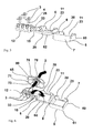
- the figure 1 is a perspective view of a first example, partial exploded, embodiment of a mobile power socket according to the invention.
- the figure 2 represents a full perspective view of the example of the figure 1 , according to an advanced stage of connection of the plug to an electric cable.
- the figure 3 is a perspective view of a second example, partial exploded, embodiment of a mobile power socket according to the invention.
- the figure 4 is a perspective view of a third example, partial exploded, embodiment of a mobile power socket according to the invention.
- the figure 5 represents a perspective view of the example of the figure 4 , partial exploded, according to a first stage of mounting of the mobile power socket.
- the figure 6 represents a full perspective view of the example of the figure 4 , according to a first stage of connection of the plug to an electric cable.
- the figure 7 represents a full perspective view of the example of the figure 4 , according to a second stage of connection of the plug to an electric cable.
- the figure 8 represents a full perspective view of the example of the figure 4 , according to a third stage of connection of the plug to an electric cable.
- the figure 9 represents a full perspective view of the example according to the figure 8 , in position ready to be connected to a fixed socket.
- the figure 10 represents a full perspective view of the example according to the figure 9 , in electrical connection position performed on a fixed power socket.
- connection plugs 3 are of known type and will therefore not be described here.
- These plugs 3 all have connection portions 4 to the respective electrical wires, with screws or self-locking type, preferably identical, in order to simplify the movable insulating support 12 which will thus comprise three preferably identical housings for the three connection plugs, respectively. All plugs for all types of connection may be suitable.
- the socket body is in the form of a small hollow housing 5 for housing the movable support 12 and the end of the electric cable 2 as shown in FIG. figure 2 .
- the figure 2 represents the socket 1 with the housing 5 open, allowing access to the mobile support 12 for connecting the electrical son 13, 14.
- This housing 5 is in a substantially parallelepipedal shape, the cutting plane defining the two parts 6, 7 of the body 5 intersecting the smaller sides of the parallelepiped, in order to offer a large access to the housing 9.
- the housing 5 has its two largest opposite faces 17, 18 respectively forming the bottoms of the two complementary parts 6 and 7 of the housing 5.
- the first passage 10 for the plugs 3 respectively comprises three indentations 21 on the upper edge of each of the two lateral walls 19 and 20 which are respectively opposite each other when the two parts of the socket body are fitted one into each other. the other, so that two notches 21 vis-à-vis define the cross section of passage of a connection plug 3, through the side peripheral walls, taken at the pin 22 of the plug, as shown on the figure 2 , or taken at the passage hole of the male pin through the side peripheral walls, in the case of a female plug.
- each plug is thus partially formed on one of the parts 6 or 7 of the socket body 5 and partly on the other part 7 or 6 of the socket body 5, so that the notches 21 intended to cooperate vis-à-vis one another, do not have undercut to match the outer shape of the cross section of the spindle 22.
- the notches 22 are formed on the same side 29 of the side walls 19 and 20 .
- the second passage 11 for the electric cable 2 through the housing 5, has a notch 23 formed on the upper edge of each of the two side walls 19 and 20 which are respectively vis-à-vis when the two parts of the body 5
- the plugs are nested one inside the other, so that two notches 23 facing each other define the transverse cross section of the electrical cable 2, as shown in FIG. figure 2 .
- the passage hole of the cable 2 is thus partially formed on one of the parts 6 or 7 of the gripping body 5 and partly on the other part 7 or 6 of the gripping body 5, so as to define a substantially circular cross-section. preferably.
- the indentations 23 are made on the same side 30 of the walls 19 and 20, and on the side opposite the indentations 21 of the connection plugs 3, so that the openings for the connection of the electrical wires 13, 14 in the appropriate holes of the plugs 3, opposite the pins for plugs males, are disposed opposite the passage 11 for the cable when the connection support 12 is placed in the housing 5 as shown in FIG. figure 2 .
- the passage 11 of the cable 2 is offset in an angle of the housing, and the housing 5 comprises, integral with one of its parts 6, 7, preferably the part to which is connected the connection support 12, an inner wall 24 disposed near the side 30 of the housing 5 having the notch 23, as shown in FIG. figure 1 or 2 , and having a passage 25, for the cable 2, forming with the passage 11 a baffle for the cable 2, which thus defines a cable gland means for protecting the electrical connection of the wires 13 and 14 formed on the connection plugs 3 tearing off via the cable 2.
- the take body 5 can adopt any form suitable for the use of mobile jack.
- the first flexible connection 8 between the first 6 and second 7 parts of the gripping body 5 preferably adopts the form of a hinge-type connection advantageously comprising a fine web of material connecting the first and second 7 parts of the body edge to edge 5, for example one of the sides 27, 28 connecting the two opposite sides 29, 30 of the housing 5 having the passages 10 and 11, respectively, as shown on FIG. the figure 1 or 2 .
- the thin web of material constituting the hinge advantageously connects the upper edges of the peripheral side walls 19 and 20, or as represented by the upper edge of the side wall 20 of the face 18 of the second portion 7 of the grip body at an edge of the face 17 of the first part 6 of the grip body.
- Such an arrangement of the thin web makes it advantageously substantially invisible and without exceeding material when the housing is closed.
- the first flexible link 8 is disposed on a first side of the tap body, and the second flexible link is disposed on a second side of the tap body, opposite the first side, so that that the movable insulating support means 12 are able to be extracted from the gripping body 5 by a rotating movement in the opposite direction to that which makes it possible to remove the first 6 and second 7 parts of the grip body.
- the insulating support means 12 insulating the two plugs constitute with the latter a mobile connection block trapping, in any known manner, the connection plugs 3, for example by clipping, interlocking or forced fitting, so that the connection plugs 3 are in the operating position when the connecting block is disposed in the housing 9 of the socket body as shown in FIG. figure 2 .
- This movable insulating support 12 has a generally parallelepipedal general shape comprising a plurality of slots for the plugs 3, in the example three slots for three plugs.
- the mobile insulating support 12 has the function of rigidly holding together the connection plugs 3, in position relative to each other to form the mobile socket 1, suitable for associating with a complementary fixed power socket (not shown for the first example).
- the movable insulating support 12 also has the function of enabling and facilitating, by its mobility, the electrical connection of the electrical wires 13, 14 to the connection plugs 3.
- the movable insulating support 12 will comprise the appropriate passages for accessing screws 26 for operating the connection means of the electric wires 13 and 14, where appropriate, when the support 12 is out of the housing 5, but preferably suitable for accessing said screw 26 when the support 12 is placed in the housing 5 as shown in FIG. figure 2 .
- the housing 5 will preferably comprise one or two stops 31, 32 for wedging the support according to the degree of freedom in translation remaining, as shown in FIGS. Figures 1 or 2 where the stops 31, 32 take the form of two ribs secured to the peripheral side wall 19 of the first part of the housing 5.
- the support 12 is preferably, in its first position, immobilized against the peripheral wall 19 on the side 29 of the housing 5, having the first passage 10 for the connection plugs 3, as shown in FIG. figure 2 .
- the second flexible link 15, more particularly visible on the figure 1 advantageously comprises a flexible fastener 33 of the strip type, adapted to allow pivoting of the movable insulating support means 12 around the band-type flexible fastener, from the first position to the second position or vice versa.
- the flexible fastener 33 is preferably bonded at one end to an edge of the first or second portion of the gripper body, and at the other end to an edge of the movable insulating support means.
- the flexible fastener 33 is for example linked at one of its ends to the upper edge of the side 28 of the peripheral side wall 19 and at the other end to the edge of the support 12 intended to come into contact with the inner face 17 of the first part of the housing 5.
- the length of the strip is determined so that the support 12 can pivot from the inside of the housing 5 to the outside of the latter, to find in a position close to the housing, and vice versa; the pivoting of the support 12 will preferably be of the order of 180 ° in order to disengage it from the housing and to facilitate the electrical connection of the electrical wires 13 and 14 by the operator, which is therefore advantageously with the support 12 outside the case.
- the connection support 12 is positioned in the housing 5, the fastener 33 has the appropriate length so that it does not protrude beyond the periphery defined by the side wall 19, so as not to impede the interlocking of the parts 6 and 7 of the grip body 5 on top of one another for closure and locking of the housing.
- the mobile insulating support 12 may consist of ribs integral with each other, defining the appropriate housing for the connection plugs 3, in order to lighten its structure.
- the locking means 16 of the first 6 and second 7 parts of the housing 5, one on the other, in the first position of the movable insulating support means 12, advantageously comprise two fasteners 34 with elastic deformation secured to the gripping body 5 , operating on the principle of the clip or the like.
- one of these fasteners 34 with elastic deformation may consist of a lug 35 projecting on the face of one of the side walls 19, 20 facing the other wall 20, 19, and a hollow 36 formed on the face of the other side walls 20, 19 facing the wall having the lug 35, adapted to receive said lug 35 when these walls 19, 20 overlap in the closed position of the housing 5 (FIG. first position defined above).
- the lug 35 will for example have an inclined face in order to facilitate the elastic deformation of the wall or walls 19, 20 so as to overlap them until the lug 35 is housed in the corresponding recess 36 on the side wall. -a-vis.
- Two fasteners 34 may for example be formed on the side 28 of the side walls 19, 20, opposite the side 27 comprising the first flexible connection 8.
- the assembly 37 constituted by the insulating gripping body, the movable insulating support 12, the locking means 16, and the two flexible links 8 and 15, is advantageously made in one piece, in one piece, made of insulating plastic material. which can advantageously be obtained by molding.
- the conductive connection plugs must be added, on the mobile support as explained above, to obtain the plug 1 of mobile power according to the invention intended to be connected to an electric cable.
- the figure 3 represents an alternative embodiment of this assembly 37 constituted by the insulating-jacketing body 5, the movable insulating support 12, the locking means 16, and the two flexible links 8 and 15, of the example of FIGS. Figures 1 and 2 , in which the represented perspective is similar to that of the figure 1 .
- references to similar elements in the first example of Figures 1 and 2 are the same.
- the whole 50 of the figure 3 is broadly similar to the whole 37 of the figure 1 , with the exception of the passage 11 of the cable 2 which no longer has a chicane in the example of the figure 3 .
- connection plugs may for example be the same as those of the example of Figures 1 and 2 .
- the figure 4 represents an alternative embodiment of the assembly 60 constituted by the insulating plug body 5, the movable insulating support 12, the locking means 16, and the two flexible links 8 and 15, of the example of FIG. figure 3 , in which the represented perspective is similar to that of the figure 1 or 3 .
- references to similar elements of the first or second example of Figures 1 and 2 , 3 are the same.
- the set 60 of the figure 4 is broadly similar to the 50 set of the figure 3 , with the exception of the passage 11 of the cable 2 which has been enlarged to accommodate sealing means (not shown in FIG. figure 4 ), which will be more widely described with the aid of the following figures 4 to 11 which relate to the third and last embodiment described.
- the body 5 of the mobile power socket 61 further comprises a flexible tongue 62, intended to lock the mobile power socket 61 inside a housing 66 from the fixed power socket 63 to the electrical connection position, as explained in detail below.
- the Figures 5 to 11 show the steps of assembly and connection of the socket 61 according to the third embodiment of the invention.
- the figure 5 represents the first step of assembling the socket 61 relating to the combination of three connection plugs 3, to the assembly 60 constituted by the insulating plug body, the movable insulating support 12, the locking means 16, and the two flexible links 8 and 15, together 60 which is advantageously made in one piece, integral, of insulating plastic material, and which may advantageously be obtained by molding.
- connection plugs 3, in the example identical may for example be the same as those of the example of the Figures 1 and 2 and correspond to flat pin plugs generally used in DCL technology, comprising, for example, screw connection means 4.
- These plugs 3 are clipped or force-fitted into three appropriate housings of the movable insulating support 12 as shown. on the figure 5 .
- the figure 6 represents the mobile socket 61 with the plugs 3 mounted, and the electric cable 2 connected to the plugs 3 by its three electrical son, phase, neutral, and earth.
- the cable 2 has been connected with the support 12 placed outside the grip body 5 and the arrow 64 shows the pivoting movement that remains to be exerted by the operator, the support 12 isolating to place it inside the housing 5 to obtain the representation of the figure 7 .
- the sealing means 65 the latter adopting in the example the form of a flexible cabochon 70 secured to the grip body via the second passage for the electrical cable 2, and covering the third side of the grip body.
- the flexible cap 70 is made for example of rubber or similar flexible waterproof material, and adopts the shape of a cap approximating a generally cone-shaped veil but whose base consists of a peripheral strip 71 material intended to be supported on the cover surface 69 of the fixed current socket 63, around the opening 67 of the housing 66 and on the edges 68 thereof.
- the band 71 of material adopts the shape of the periphery of the opening 67 of the housing 66, and from this periphery, the tightness of the cap 70 is raised with a slope towards the cable 2, the top 72 of the cap being perforated to the passage of this cable, as shown on the Figures 6 to 11 .
- the flexible cap 70 also seals around the electric cable 2 by the walls of the top hole 72 of the cap 70, which bear on the periphery of a cross section of the cable 2.
- the cap 70 advantageously comprises a ring 73 to the inside the top thereof, for example round, oval as shown or square, intended to be put into force in the passage 11 of cable 2 of the housing 5 socket 61 mobile, via the notches 23, as shown in the figure 8 .
- the operator slides the cabochon 70 along the cable 2, along the arrow 74 of the figure 7 , so that the ring 73 is positioned in the notch 23 of the first part 6 of the gripping body 5, then obtaining a mounting stage of the socket 61 shown in FIG.
- the ring 73 which is preferably one-piece with the cap web to form the cap 70, is of elastic material and is placed in force in the notch 23, then in the other notch 23 forming with the first the passage 11 of the housing 5, in order to advantageously seal between the housing 5 of the movable socket and the ring 73, insofar as the housing 5 is itself sealed.
- the ring 73 may include a groove 80 intended to house the edges of the notches 23 and thus make a solid connection preventing the cabochon out of its housing and slide along the cable 2.
- the operator (not shown) must now close the housing 5 of the mobile socket by pivoting the housing part 7 around the hinge-shaped flexible connection 8, along the arrow 75 on the figure 8 , part 7 performing for this purpose a rotation of about 180 °.
- the part 7 is placed around the ring 73 of the cabochon 70 in order to accomplish the fixing of the sealing cap 70 on the gripping body 5, and around the pins of the plugs 3 of connection to immobilize also with respect to the housing 5 the support 12 and its connection plugs.
- the elastic tongue 62 has shoulders 77 is clipped into a recess 76 is provided for this purpose in the housing 66 at the end of connection; the recess 76 is provided to allow the free passage of the tongue in the housing 66 throughout the insertion of the socket 61.
- the end of the tongue 62 protrudes out of the housing 66 so that an operator can grasp and manipulate the tongue 62 so as to release the lock provided by the shoulders 77, and remove the socket 61 of the housing 66.
- Such a locking technology of the socket 61 in the socket 63 is known in itself, for example in DCL technology.
- the flexible cap 70 advantageously comprises at least one protrusion 78 on its outer surface defining a recess 79 on its inner opposite surface, in which is intended to be housed the free end of the flexible tongue 62, when the cabochon 70 is in place on the socket body 61, as shown in the figure 9 .
- two protuberances 78 are formed on the cap 70, arranged diametrically opposite to each other with respect to the axis of the cable 2 so as not to index it, or to be suitable for a socket comprising two flexible tongues 62.
- a protrusion 78 must be provided to allow free movement of the tongue 62 so as not to impede its locking in the housing 66.
- the cabochon 70 extends all around the gripping body 5, in order to leave the contact strip 71 of the cabochon intended to rest on the surface 69 of the fixed catch 63.
- the band 70 will preferably be parallel or substantially to the outer surface of the case body 5, to ensure a relatively constant sealing safety distance with the edges of the opening 67, and therefore, its shape will preferably be defined at from the outer shape of the housing 5, itself in accordance with the shape of the housing 66 of the fixed grip 63.
- the band 70 adopts a rectangular shape with rounded corners.
- the tongue 62 also serving as a commitment key, until a click is heard, informing the operator that the plug 61 is connected and locked in its housing 66.
- the click is conferred by the triggering the locking of the tongue 62 at the end of the connection.
- the cap 70 attached to the body 5 of the socket 61 has been pressurized against the cover surface 69 of the fixed socket 63, establishing a tight connection between the mobile socket 61 and the fixed socket 63, as shown in FIG. the figure 11 .
- the recessed housing portion of the fixed socket 63 has not been shown in the figures because this type of recess box is widely known to those skilled in the art.
- the represented part of the fixed grip 63 on the Figures 10 and 11 consists of the receptacle with its housing 66, associated with the cover plate 69 of the recess box by means of two screws (not shown), the passage holes 81 of which are visible on the Figures 10 and 11 .
- the Figures 10 and 11 show also an electrical cable 82 for connecting the fixed socket 63.
Landscapes
- Connector Housings Or Holding Contact Members (AREA)
- Details Of Connecting Devices For Male And Female Coupling (AREA)
- Coupling Device And Connection With Printed Circuit (AREA)
Abstract
Description
La présente invention se rapporte à une prise de courant mobile, de type mâle et/ou femelle, destinée à être prise en main pour être associée à une prise de courant fixe de type femelle et/ou mâle respectivement complémentaire, en vue d'établir un branchement électrique, et destinée en outre à être raccordée à au moins un câble électrique. Une telle prise de courant mobile est utilisable pour permettre le branchement électrique de tout appareil électrique, et notamment d'un luminaire. La prise de courant mobile selon l'invention est plus particulièrement adaptée dans le cadre des Dispositifs de Connexion Luminaire, dit DCL. Par prise de courant fixe, on entend pour la présente invention essentiellement une prise de courant d'une installation électrique par exemple d'une construction immobilière ou analogue, mais également d'une construction mobile à destination d'habitation, fixée à ladite construction, à un mur, un plafond ou un sol. Par prise de courant fixe, on entend également une prise sur un appareil mobile, par exemple un générateur d'électricité, mais dont la destination est d'être placé à un endroit déterminé en vue de permettre le branchement électrique d'un appareil électrique.The present invention relates to a mobile power outlet, of the male and / or female type, intended to be taken in hand to be associated with a fixed socket of the female and / or male respectively complementary type, in order to establish an electrical connection, and further intended to be connected to at least one electrical cable. Such a mobile power outlet is used to allow the electrical connection of any electrical device, including a luminaire. The mobile power socket according to the invention is more particularly suitable in the context of the Lighting Connection Devices, said DCL. By fixed current socket is meant for the present invention essentially a power outlet of an electrical installation for example of a building or similar construction, but also a mobile construction for residential purpose, fixed to said construction, to a wall, ceiling or floor. By fixed power socket is also meant a plug on a mobile device, for example an electricity generator, but the destination is to be placed at a specific location to allow the electrical connection of an electrical device.
De telles prises de courant mobiles sont connues de l'art antérieur, cependant, elles présentent l'inconvénient de nécessiter un temps important pour réaliser le raccordement du ou des câbles électriques à la prise, généralement trois raccordements, phase, neutre et terre. En outre, ces prises de courant mobiles connues se présentent le plus communément sous la forme d'au moins deux pièces assemblées l'une à l'autre, souvent de taille assez petite et que l'on peut perdre ou lâcher relativement facilement, donc peu ergonomiques.Such mobile power outlets are known from the prior art, however, they have the disadvantage of requiring a significant time to achieve the connection of the electric cable or cables to the socket, usually three connections, phase, neutral and earth. In addition, these known mobile power outlets are most commonly in the form of at least two pieces assembled to each other, often of a fairly small size and that can be lost or dropped relatively easily, so not very ergonomic.
On connaît en outre du document
- un bloc de connexion comportant plusieurs fiches de connexion conductrices dotées respectivement des moyens de raccordement à un câble électrique,
- un corps de prise isolant, comprenant une première et une deuxième parties latérales, et une paroi de bout formée par le bloc de connexion, les parties latérales et la paroi de bout étant liées deux à deux les unes aux autres par des liaisons souples, mobiles les unes par rapport aux autres, et destinées à être emboîtées les unes dans autres pour former le corps de prise. Une telle prise facilite et améliore la rapidité de la connexion des fils électriques, et évite la perte d'accessoires, mais n'apporte pas toute satisfaction, notamment en matière de compacité, rigidité, solidité, et ergonomie.
- a connection block comprising a plurality of conductive connection plugs respectively provided with means for connecting to an electric cable,
- an insulative plug body, comprising a first and a second side portion, and an end wall formed by the plug block, the side portions and the end wall being connected in pairs by flexible, movable links; the ones with respect to the others, and intended to be nested in one another to form the body of capture. Such a plug facilitates and improves the speed of the connection of electrical wires, and avoids the loss of accessories, but does not provide any satisfaction, especially in terms of compactness, rigidity, strength, and ergonomics.
On connaît également le document
La présente invention se propose de pallier ces inconvénients et d'apporter d'autres avantages. Plus précisément, elle consiste en une prise de courant mobile, de type mâle et/ou femelle, destinée à être prise en main pour être associée à une prise de courant fixe complémentaire, en vue d'établir un branchement électrique, et destinée en outre à être raccordée à un câble électrique, comprenant :
- au moins une fiche de connexion conductrice comportant des moyens de raccordement à au moins un fil électrique dudit câble électrique,
- un corps de prise isolant, comprenant une première et une deuxième parties, emboîtées l'une sur l'autre et liées l'une à l'autre par une première liaison souple, en sorte qu'un logement soit défini à l'intérieur desdites première et deuxième parties,
- des moyens de support isolant de ladite au moins une fiche de connexion, mobile par rapport au dit corps de prise, liés à l'une desdites première ou deuxième partie dudit corps de prise, par une deuxième liaison souple en sorte de permettre deux positions au moins desdits moyens de support isolant mobile,
- lesdites première et deuxième parties dudit corps de prise forment boîtier lorsqu'elles sont emboîtées l'une sur l'autre, et définissent au moins un premier passage pour ladite au moins une fiche de connexion, et un deuxième passage pour ledit au moins un câble électrique, ledit logement étant accessible à partir de l'extérieur dudit corps de prise par écartement desdites première et deuxième parties l'une de l'autre, en ce que
- lesdites deux positions au moins desdits moyens de support isolant mobile sont définies comme suit :
- * une première position dans laquelle lesdits moyens de support isolant mobile sont logés dans le corps de prise de telle sorte que ladite au moins une fiche de connexion soit accessible à partir de l'extérieur du corps de prise via ledit premier passage, lesdites première et deuxième parties dudit corps de prise étant emboîtées l'une sur l'autre, et
- * une deuxième position dans laquelle lesdits moyens de support isolant mobile sont placés à l'extérieur du corps de prise, lesdites première et deuxième parties de ce dernier étant écartées l'une sur l'autre, et en ce que
- ladite prise de courant comprend des moyens de verrouillage desdites première et deuxième parties du corps de prise, l'une sur l'autre, dans ladite première position desdits moyens de support isolant mobile.
- at least one conductive connection plug comprising means for connecting to at least one electrical wire of said electrical cable,
- an insulative plug body, comprising a first and a second portion, interlocked with one another and bonded to each other by a first flexible connection, such that a recess is defined within said first and second parts,
- insulating support means of said at least one connecting plug, movable relative to said plug body, connected to one of said first or second part of said socket body, by a second flexible connection so as to allow two positions in the least of said movable insulating support means,
- said first and second portions of said socket body form a housing when nested one upon the other, and define at least a first passage for said at least one connection plug, and a second passage for said at least one cable electrical, said housing being accessible from the outside of said socket body by spacing said first and second parts from each other, in that
- said at least two positions of said movable insulating support means are defined as follows:
- a first position in which said movable insulating support means are housed in the socket body so that said at least one plug is accessible from the outside of the socket body via said first passage, said first and second portions of said grip body being interlocked with one another, and
- a second position in which said movable insulating support means are placed outside the plug body, said first and second parts of the latter being spaced apart from one another, and in that
- said socket comprises means for locking said first and second parts of the socket body, one on the other, in said first position of said movable insulating support means.
La prise de courant mobile selon l'invention offre une bonne ergonomie en ce que l'ensemble isolant de la prise, grâce à la double liaison souple et la mobilité du support de connexion par rapport au corps de prise, peut avantageusement être constitué d'une seule pièce, monobloc, la ou les fiches de connexion conductrices étant rapportées par tout moyen connu par exemple par clipsage ou analogue. Le raccordement électrique de la prise selon l'invention à un câble est ainsi effectué de manière pratique, après avoir sorti du corps de prise les moyens de support isolant mobile qui portent la ou les fiches de connexion, et raccordé le câble à ces fiches de connexion, puis réinséré les moyens de support isolant mobile dans le corps de prise, aucune pièce annexe de la prise ne pouvant être lâchée ou perdue par l'opérateur qui effectue le raccordement électrique. En outre, l'ensemble isolant de la prise de courant, constitué d'une seule pièce, peut avantageusement être obtenu par moulage à partir d'un moule unique ce qui permet de réduire les coûts de fabrication. En outre, la prise de courant selon l'invention offre une bonne compacité, rigidité, solidité, et ergonomie, du fait de l'insertion des moyens de support des fiches à l'intérieur du corps de prise, les deux parties de ce corps de prise définissant un passage pour la ou les fiches.The mobile power socket according to the invention offers good ergonomics in that the insulating assembly of the socket, thanks to the flexible double connection and the mobility of the connection support with respect to the socket body, can advantageously consist of one piece, monobloc, or the conductive connection plugs being reported by any known means for example clipping or the like. The electrical connection of the socket according to the invention to a cable is thus carried out in a practical manner, after having removed from the socket body the movable insulating support means which carry the connection plug or plugs, and connected the cable to these plugs of connection, then reinserted the movable insulating support means in the socket body, no accessory part of the socket can not be dropped or lost by the operator who makes the electrical connection. In addition, the insulating assembly of the socket, consisting of a single piece, can advantageously be obtained by molding from a single mold which reduces manufacturing costs. In addition, the socket according to the invention offers good compactness, rigidity, strength, and ergonomics, because of the insertion of the means for supporting the plugs inside the socket body, the two parts of this body socket defining a passage for the one or more sheets.
Selon une caractéristique avantageuse, ladite au moins une fiche de connexion est une fiche mâle.According to an advantageous characteristic, said at least one connection plug is a plug.
Selon une caractéristique avantageuse, ladite au moins une fiche de connexion est une fiche femelle.According to an advantageous characteristic, said at least one connection plug is a female plug.
Selon une caractéristique avantageuse, ladite première liaison souple entre les première et deuxième parties dudit corps de prise adopte la forme d'une liaison de type charnière comportant au moins un voile fin de matière reliant bord à bord lesdites première et deuxième parties du corps de prise.According to an advantageous characteristic, said first flexible connection between first and second parts of said plug body adopt the form of a hinge type connection comprising at least one thin web of material connecting edge to edge said first and second parts of the socket body.
Selon une caractéristique avantageuse de la précédente, ledit au moins un voile fin de matière est rectiligne.According to an advantageous characteristic of the preceding one, said at least one fine web of material is rectilinear.
Selon une caractéristique avantageuse, ladite première liaison souple est disposée sur un premier côté dudit corps de prise, et ladite deuxième liaison souple est disposée sur un deuxième côté dudit corps de prise, opposé au dit premier côté, de telle sorte que lesdits moyens de support isolant mobile soient aptes à être extraits dudit corps de prise par un mouvement tournant dans le sens inverse de celui permettant d'écarter les première et deuxième parties du corps de prise.According to an advantageous characteristic, said first flexible connection is disposed on a first side of said grip body, and said second flexible connection is disposed on a second side of said grip body, opposite said first side, so that said support means movable insulation are able to be extracted from said grip body by a rotating movement in the opposite direction to that for moving apart the first and second parts of the grip body.
Selon une caractéristique avantageuse, ladite deuxième liaison souple comporte au moins une attache souple du type bande, apte à permettre un pivotement desdits moyens de support isolant mobile autour de ladite attache souple du type bande de ladite première position vers ladite deuxième position ou inversement.According to an advantageous characteristic, said second flexible connection comprises at least one band-type flexible fastener, adapted to allow said movable insulating support means to pivot about said band-type flexible fastener from said first position to said second position or vice versa.
Selon une caractéristique avantageuse, ladite deuxième liaison souple comporte au moins une attache souple du type bande liée par une de ses extrémités à un bord de ladite première ou deuxième partie dudit corps de prise, et par l'autre de ses extrémités à un bord desdits moyens de support isolant mobile.According to an advantageous characteristic, said second flexible connection comprises at least one flexible fastener of the strip type linked by one of its ends to an edge of said first or second part of said grip body, and by the other of its ends to an edge of said mobile insulating support means.
Selon une caractéristique avantageuse, lesdits moyens de verrouillage desdites première et deuxième parties, l'une sur l'autre, dans ladite première position desdits moyens de support isolant mobile, comprennent au moins une attache à déformation élastique solidaire dudit corps de prise.According to an advantageous characteristic, said means for locking said first and second parts, one on the other, in said first position of said movable insulating support means comprise at least one resiliently deforming fastener integral with said gripping body.
Cette caractéristique offre un moyen ergonomique et rapide de verrouiller le boîtier constitutif du corps de prise après avoir raccordé le câble électrique et replacé les moyens de support isolant mobile dans le corps de prise, par une simple opération de clipsage ou analogue.This feature provides an ergonomic and quick way to lock the housing constituting the socket body after connecting the power cable and replaced the movable insulating support means in the socket body, by a simple clipping operation or the like.
Selon une caractéristique avantageuse, ladite au moins une fiche de connexion comporte des moyens de raccordement à un câble électrique, de type à vis ou autobloquant.According to an advantageous characteristic, said at least one connection plug comprises means for connecting to an electric cable, screw type or self-locking.
Selon une caractéristique avantageuse de l'invention, la prise de courant mobile selon l'invention comprend des moyens d'étanchéité dudit branchement électrique, disposés sur un troisième côté dudit corps de prise, opposé à un quatrième côté dudit corps de prise à partir duquel est accessible de l'extérieur ladite au moins une fiche de connexion,
- ladite prise de courant fixe comprenant :
- un logement au fond duquel est disposée au moins une fiche de branchement électrique, complémentaire de ladite au moins une fiche de connexion de ladite prise de courant mobile,
- une ouverture d'entrée dudit logement comportant des bords définis par une surface de couverture de ladite prise de courant fixe,
- ledit logement étant apte à loger ladite prise de courant mobile en sorte que ledit corps de prise de courant mobile soit encastré au moins en partie dans ledit logement de la prise de courant fixe lorsque ladite prise de courant mobile est branchée dans ladite prise de courant fixe,
- lesdits moyens d'étanchéité couvrant lesdits bords de ladite ouverture dudit logement de la prise de courant fixe.
- said fixed socket comprising:
- a housing at the bottom of which is disposed at least one electrical connection plug, complementary to said at least one plug of said mobile power socket,
- an inlet opening of said housing having edges defined by a covering surface of said fixed electrical outlet,
- said housing being adapted to accommodate said mobile power socket so that said movable socket body is recessed at least partially in said socket of the fixed power socket when said mobile power socket is connected to said fixed power socket ,
- said sealing means covering said edges of said opening of said housing of the fixed power socket.
Il est à noter que cette caractéristique d'étanchéité du branchement électrique peut être rendue indépendante de l'invention telle que caractérisée plus haut et répond à un problème technique différent de celui ou ceux déjà énoncés. Toutefois, cette caractéristique d'étanchéité reste dans le domaine technique tel que défini en début du présent mémoire. En effet, cette caractéristique de moyens d'étanchéité, prise en dépendance de la présente invention ou considérée de manière indépendante, permet de réaliser l'étanchéité du branchement électrique lorsqu'une prise de courant mobile est insérée dans le logement complémentaire d'une prise de courant fixe, la prise de courant mobile étant encastrée dans la prise de courant fixe, afin de réaliser un branchement électrique entre la prise mobile et la prise fixe, comme c'est par exemple le cas avec la technologie DCL dans laquelle la prise de courant mobile raccordée au luminaire est insérée dans un logement réalisé dans un boîtier de branchement électrique fixe généralement encastré dans la maçonnerie, plafond ou mur. Le logement réalisé dans le boîtier de branchement encastré ou prise fixe permet de loger la prise de courant mobile en sorte que seul le câble électrique dépasse dudit logement. Les moyens d'étanchéité tels que définis ci-dessus, disposés sur un côté du corps de prise opposé à celui où sont réalisés les passages des fiches de branchement ou de connexion, permettent avantageusement d'assurer l'étanchéité du branchement électrique par recouvrement de l'ouverture du logement du boîtier de branchement dans lequel la prise de courant selon l'invention est logée pour réaliser un branchement électrique, en fin d'insertion de la prise mobile dans le logement de la prise fixe, les moyens d'étanchéité venant couvrir les bords dudit logement de la prise fixe en vue d'empêcher tout liquide de pénétrer dans ledit logement.It should be noted that this sealing characteristic of the electrical connection can be made independent of the invention as characterized above and responds to a different technical problem from those already stated. However, this sealing characteristic remains in the technical field as defined at the beginning of this memo. Indeed, this characteristic of sealing means, taken in dependence of the present invention or considered independently, makes it possible to seal the electrical connection when a mobile power socket is inserted into the complementary housing of a socket of fixed current, the mobile power socket being embedded in the fixed power socket, in order to make an electrical connection between the mobile socket and the fixed socket, as is the case, for example, with the DCL technology in which the mobile power connected to the luminaire is inserted in a housing made in a fixed electrical connection box generally embedded in the masonry, ceiling or wall. The housing made in the recessed connection box or fixed socket allows housing the mobile socket so that only the electrical cable protrudes from said housing. The sealing means as defined above, arranged on one side of the socket body opposite to that where the passages of the connection or connection plugs are made, advantageously make it possible to seal the electrical connection by covering the opening of the housing of the connection box in which the socket according to the invention is housed to make an electrical connection, at the end of insertion of the mobile socket in the housing of the fixed socket, the sealing means covering the edges of said housing of the fixed grip in order to prevent any liquid from entering said housing.
Cette caractéristique de moyens d'étanchéité telle que définie ci-dessus peut ainsi être appliquée à toute prise de courant mobile, de type mâle et/ou femelle, destinée à être prise en main pour être associée à une prise de courant fixe de type femelle et/ou mâle respectivement complémentaire, en vue d'établir un branchement électrique, et destinée en outre à être raccordée à au moins un câble électrique, ladite prise de courant mobile comprenant :
- au moins une fiche de connexion conductrice dotée de moyens de raccordement à un câble électrique,
- un corps de prise isolant, incluant ladite au moins une fiche de connexion, définissant au moins un premier passage pour ladite au moins une fiche de connexion, et un deuxième passage pour ledit câble électrique.
- at least one conductive connection plug provided with means for connection to an electric cable,
- an insulative plug body, including said at least one plug, defining at least a first passage for said at least one plug, and a second passage for said electrical cable.
Selon une caractéristique de la présente invention, lesdits moyens d'étanchéité adoptent la forme d'un cabochon souple solidaire dudit corps de prise via ledit deuxième passage pour ledit câble électrique, et couvrant ledit troisième côté dudit corps de prise.According to a feature of the present invention, said sealing means take the form of a flexible cap secured to said jack body via said second passage for said electric cable, and covering said third side of said jack body.
Cette caractéristique s'applique également à la caractéristique des moyens d'étanchéité prise de manière indépendante par rapport à la présente invention comme expliqué ci-dessus. Cette caractéristique propose un mode de fixation du cabochon pratique et ergonomique conférant une fonction d'étanchéité double au dit cabochon : la réalisation de l'étanchéité du branchement électrique à la fois vis-à-vis du logement de la prise fixe et vis-à-vis du câble électrique raccordé à la prise mobile.This characteristic also applies to the characteristic of the sealing means taken independently of the present invention as explained above. This feature provides a convenient and ergonomic cabochon attachment mode conferring a double sealing function to said cabochon: the achievement of the sealing of the electrical connection both vis-à-vis the housing of the fixed socket and vis-à-vis -vis the electrical cable connected to the mobile socket.
Selon une caractéristique de la présente invention,
- ledit corps de prise de la prise de courant mobile comporte une languette flexible, destinée à verrouiller ladite prise de courant mobile à l'intérieur dudit logement de ladite prise de courant fixe en position de branchement électrique, et
- lesdits moyens d'étanchéité adoptent une forme apte à couvrir les bords de l'ouverture dudit logement et ladite languette flexible en sorte de rendre étanche la connexion de ladite prise de courant mobile dans ladite prise de courant fixe.
- said socket body of the mobile power socket has a flexible tongue for locking said movable power socket within said housing of said fixed power socket in the electrical connection position, and
- said sealing means adopt a shape adapted to cover the edges of the opening said housing and said flexible tongue so as to seal the connection of said mobile power socket in said fixed power socket.
Cette caractéristique s'applique également à la caractéristique des moyens d'étanchéité prise de manière indépendante par rapport à la présente invention comme expliqué ci-dessus. Elle se rapporte plus particulièrement à la technologie DCL dans laquelle une prise mobile est munie d'une languette de verrouillage du branchement électrique, cette languette flexible possédant une première extrémité fixée au corps de prise, généralement dans la zone de la prise se situant au fond du logement, et une deuxième extrémité, libre, opposée à la première et affleurant l'ouverture du logement ou dépassant celle-ci, et par laquelle un opérateur peut déverrouiller la prise de courant mobile afin de la retirer hors du logement et ainsi débrancher la prise.This characteristic also applies to the characteristic of the sealing means taken independently of the present invention as explained above. It relates more particularly to the DCL technology in which a mobile socket is provided with a locking tab of the electrical connection, this flexible tongue having a first end fixed to the socket body, generally in the area of the socket located at the bottom housing, and a second end, free, opposite to the first and flush with the opening of the housing or beyond it, and by which an operator can unlock the mobile power socket to remove it from the housing and thus disconnect the outlet.
Selon une caractéristique de la présente invention, dépendante des deux précédentes, ledit cabochon souple comporte au moins une protubérance sur sa surface extérieure définissant un creux sur sa surface opposée intérieure, dans lequel est destinée à être logée une extrémité libre de ladite languette flexible.According to a feature of the present invention, dependent on the two preceding, said flexible cabochon comprises at least one protuberance on its outer surface defining a recess on its inner opposite surface, in which is intended to be housed a free end of said flexible tongue.
Cette caractéristique s'applique également à la caractéristique des moyens d'étanchéité prise de manière indépendante par rapport à la présente invention comme expliqué ci-dessus. Elle offre une solution permettant à la fois de concilier étanchéité du branchement électrique et manoeuvre par un opérateur de la languette afin de retirer la prise.This characteristic also applies to the characteristic of the sealing means taken independently of the present invention as explained above. It offers a solution to reconcile the tightness of the electrical connection and maneuvering by an operator of the tongue to remove the plug.
D'autres caractéristiques et avantages de la présente invention apparaîtront à la lecture qui suit de plusieurs exemples de mode de réalisation de l'invention, accompagnée des dessins annexés, exemples donnés à titre illustratif non limitatif.Other features and advantages of the present invention will appear on reading the following examples of several embodiments of the invention, accompanied by the accompanying drawings, examples given by way of non-limiting illustration.
La
La
La
La
La
La
La
La
La
La
Le premier exemple de mode de réalisation de prise de courant mobile selon l'invention représenté sur les
- deux
fiches 3 de connexion conductrice, du type fiche mâle, comportant des moyens 4 de raccordement aux deux fils électriques 13, 14 du câble électrique 2, respectivement, un corps 5 de prise isolant formant boîtier, comprenant une première 6 et une deuxième 7 parties, emboîtées l'une sur l'autre et liées l'une à l'autre par unepremière liaison 8 souple, en sorte qu'un logement 9 soit défini à l'intérieur des première 6 etdeuxième 7 parties,ce logement 9 étant accessible à partir de l'extérieur du corps 5 de prise par écartement des première 6 etdeuxième 7 parties l'une de l'autre, ces première 6 etdeuxième 7 parties ducorps 5, lorsqu'elles sont emboîtées l'une sur l'autre, définissantun premier passage 10 pour les deux fiches 3 de connexion, respectivement et un deuxièmepassage 11 de traversée pour le câble électrique 2,- des moyens de
support 12 isolant des deux fiches 3 de connexion,le support 12 étant mobile parrapport au corps 5 de prise, liés par exemple à la première partie 6 de ce dernier, parune deuxième liaison 15 souple en sorte de permettre deux positions au moins des moyens desupport 12 isolant mobile, comme suit :- * une première position, comme représenté sur la
figure 2 , dans laquelle les moyens desupport 12 isolant mobile sont logés dans le corps 5 de prise de telle sorte que les deux fiches 3 de connexion soient accessibles à partir de l'extérieur du corps 5 de prise via lepremier passage 10, les première 6 etdeuxième 7 parties ducorps 5 de prise étant emboîtées l'une sur l'autre (non représenté sur lafigure 2 ), et - * une deuxième position, comme représenté sur la
figure 1 , dans laquelle les moyens desupport 12 isolant mobile sont placés à l'extérieur du corps 5 de prise, les première 6 etdeuxième 7 parties de ce dernier étant écartées l'une sur l'autre,
- * une première position, comme représenté sur la
- des moyens de verrouillage 16 des
première 6 etdeuxième 7 parties ducorps 5 de prise, l'une sur l'autre, dans la première position des moyens desupport 12 isolant mobile.
- two
plugs 3 of conductive connection, plug type, havingmeans 4 for connection to twoelectrical son electric cable 2, respectively, - an insulating housing-forming
body 5, comprising a first 6 and a second 7 parts, nested one on the other and connected to each other by a firstflexible connection 8, so that ahousing 9 is defined inside the first 6 and second 7 parts, thishousing 9 being accessible from the outside of thebody 5 taken by spacing the first 6 and second 7 parts from each other, these first 6 and second 7 parts of thebody 5, when they are fitted one on the other, defining afirst passage 10 for the two connection plugs 3, respectively and asecond passage 11 for theelectrical cable 2, - support means 12 insulating the two connection plugs 3, the
support 12 being movable relative to thesocket body 5, for example connected to thefirst part 6 of the latter, by a secondflexible connection 15 so as to allow two positions at least one movable insulating support means 12, as follows:- * a first position, as shown on the
figure 2 , in which movable insulating support means 12 are accommodated in thesocket body 5 so that the two connection plugs 3 are accessible from the outside of thesocket body 5 via thefirst passage 10, the first 6 and second 7 parts. of thegripping body 5 being interlocked with one another (not shown on thefigure 2 ), and - * a second position, as shown on the
figure 1 in which the movable insulating support means 12 are placed outside the gripping body, the first 6 and second 7 parts thereof being spaced apart from one another,
- * a first position, as shown on the
- locking means 16 of the first 6 and second 7 parts of the
gripping body 5, one on the other, in the first position of the movable insulating support means 12.
La prise 1 des
Le corps de prise adopte la forme d'un petit boîtier 5 creux servant à loger le support 12 mobile et l'extrémité du câble électrique 2 comme représenté sur la
Les deux faces 17 et 18 sont respectivement surmontée sur leur périphérie par deux parois latérales 19, 20 :
- dont les bords supérieurs peuvent venir en contact l'un avec l'autre, avec un moyen de centrage, lorsque le boîtier 5 de prise est fermé dans la première position des moyens 12 de support mobile (position complète non représentée pour l'exemple des
figures 1 , et représentée partiellement sur laet 2figure 2 ), ou - s'emboîtant l'une dans l'autre, dans ce dernier cas une des parois latérales 19, 20 pouvant venir en appui sur la face opposée, respectivement 18, 17. Dans l'exemple des
figures 1 représenté, la paroi latérale périphérique 20 de laet 2face 18 s'emboîte autour de la paroi périphérique latérale 19 de laface 17, et le bord supérieur de la paroi périphérique latérale 20 vient en appui sur les bords de laface 17.
- whose upper edges can come into contact with each other, with a centering means, when the
engagement housing 5 is closed in the first position of the movable support means 12 (complete position not shown for the example of theFigures 1 and 2 , and partially represented on thefigure 2 ), or - fitting one into the other, in the latter case one of the
side walls Figures 1 and 2 shown, the peripherallateral wall 20 of theface 18 fits around the lateralperipheral wall 19 of theface 17, and the upper edge of the lateralperipheral wall 20 bears on the edges of theface 17.
Le premier passage 10 pour les fiches 3 comporte respectivement trois échancrures 21 sur le bord supérieur de chacune des deux parois latérales 19 et 20 qui se trouvent respectivement en vis-à-vis lorsque les deux parties du corps de prise sont emboîtées l'une dans l'autre, en sorte que deux échancrures 21 en vis-à-vis définissent la section transversale de passage d'une fiche 3 de connexion, à travers les parois périphériques latérales, prise au niveau de la broche 22 de la fiche, comme représenté sur la
Le deuxième passage 11 pour le câble électrique 2 à travers le boîtier 5, comporte une échancrure 23 réalisée sur le bord supérieur de chacune des deux parois latérales 19 et 20 qui se trouvent respectivement en vis-à-vis lorsque les deux parties du corps 5 de prise sont emboîtées l'une dans l'autre, en sorte que deux échancrures 23 en vis-à-vis définissent la section transversale de passage du câble électrique 2, comme représenté sur la
Dans l'exemple des
Le corps 5 de prise peut adopter toute forme appropriée à l'usage de prise mobile.The
La première liaison 8 souple entre les première 6 et deuxième 7 parties du corps 5 de prise adopte de préférence la forme d'une liaison de type charnière comportant avantageusement un voile fin de matière reliant bord à bord les première 6 et deuxième 7 parties du corps 5 de prise, de préférence le long d'un côté 27 rectiligne du boîtier 5, par exemple un 27 des côtés 27, 28 reliant les deux côtés 29, 30 opposés du boîtier 5 comportant les passages 10 et 11, respectivement, comme représenté sur la
De manière avantageuse, la première liaison 8 souple est disposée sur un premier 27 côté du corps 5 de prise, et la deuxième liaison 15 souple est disposée sur un deuxième 28 côté du corps 5 de prise, opposé au premier 27 côté, de telle sorte que les moyens de support 12 isolant mobile soient aptes à être extraits du corps 5 de prise par un mouvement tournant dans le sens inverse de celui permettant d'écarter les première 6 et deuxième 7 parties du corps 5 de prise.Advantageously, the first
Les moyens de support 12 isolant des deux fiches constituent avec ces dernières un bloc de connexion mobile emprisonnant, de toute manière connue, les fiches 3 de connexion, par exemple par clipsage, emboîtement ou emmanchement forcé, en sorte que les fiches 3 de connexion se trouvent en position de fonctionnement lorsque le boc de connexion est disposé dans le logement 9 du corps de prise comme représenté sur la
Le support isolant mobile 12 adoptera des contours extérieurs tels qu'il sera avantageusement automatiquement immobilisé au contact entre les parois 17, 18, 19, et 20 du boîtier 5 lorsqu'il est placé à l'intérieur du boîtier dans la première position des moyens de support 12 isolant. Dans la mesure où le volume du support 12 est largement inférieur à celui du logement 9, ce qui est le cas dans l'exemple représenté et ceci afin de loger, dans le boîtier 5, l'extrémité du câble 2 comme représenté sur la
La deuxième liaison 15 souple, plus particulièrement visible sur la
Comme représenté, le support 12 isolant mobile peut être constitué de nervures solidaires les unes des autres, définissant les logements appropriés pour les fiches 3 de connexion, afin d'alléger sa structure.As shown, the mobile insulating
Les moyens de verrouillage 16 des première 6 et deuxième 7 parties du boîtier 5, l'une sur l'autre, dans la première position des moyens de support 12 isolant mobile, comprennent avantageusement deux attaches 34 à déformation élastique solidaire du corps 5 de prise, fonctionnant sur le principe du clip ou analogue. Par exemple, une de ces attaches 34 à déformation élastique peut être constituée d'un ergot 35 saillant sur la face d'une des parois latérales 19, 20 en vis à vis de l'autre paroi 20, 19, et d'un creux 36 formé sur la face de l'autre des parois latérales 20, 19 en vis à vis de la paroi comportant l'ergot 35, apte à recevoir ledit ergot 35 lorsque ces parois 19, 20 se recouvrent en position de fermeture du boîtier 5 (première position définie plus haut). L'ergot 35 présentera par exemple une face inclinée afin de faciliter la déformation élastique de la ou les parois 19, 20 en vue de leur recouvrement jusqu'à ce que cet ergot 35 se loge dans le creux 36 correspondant sur la paroi latérale en vis-à-vis. Deux attaches 34 peuvent par exemple, être formées sur le côté 28 des parois latérales 19, 20, opposé au côté 27 comportant la première liaison souple 8.The locking means 16 of the first 6 and second 7 parts of the
Dans l'exemple représenté sur les
La
La
Dans l'exemple de prise de courant mobile selon l'invention des
Les
La
La
La prise de courant 61 mobile de la
- la prise 63 de courant fixe comprenant, comme représenté sur la
figure 10 ou 11 :- un logement 66 au fond duquel sont disposées trois fiches femelles (non représentées) de branchement électrique, complémentaires respectivement des trois fiches 3 de connexion mâle de la prise 61 de courant mobile,
- une ouverture 67 d'entrée du logement 66 comportant des bords 68 définis par une surface de couverture 69 de la prise 63 de courant fixe,
- le logement 66 étant apte à loger la prise 61 de courant mobile en sorte que le corps 5 de la prise 61 de courant mobile soit encastré au moins en partie dans le logement 66 de la prise 63 de courant fixe lorsque la prise 61 de courant mobile est branchée dans la prise 63 de courant fixe,
- les moyens d'étanchéité 65 couvrant les bords 68 de l'ouverture 67 du logement 66 de la prise 63 de courant fixe.
- the fixed
current tap 63 comprising, as shown in FIG.figure 10 or 11 :- a
housing 66 at the bottom of which are arranged three female plugs (not shown) of electrical connection, respectively complementary to the threeplugs 3 of male connection of thesocket 61 of the mobile current, - an
inlet opening 67 of thehousing 66 havingedges 68 defined by a coveringsurface 69 of the fixedcurrent socket 63, - the
housing 66 being able to accommodate themobile power socket 61 so that thebody 5 of themobile power socket 61 is recessed at least partly in thehousing 66 of the fixedcurrent socket 63 when themobile power socket 61 is connected to the fixedcurrent socket 63,
- a
- the sealing means 65 covering the
edges 68 of theopening 67 of thehousing 66 of the fixedcurrent socket 63.
À l'étape de montage de la
Le cabochon 70 souple est réalisé par exemple en caoutchouc ou matière étanche souple analogue, et adopte la forme d'un chapeau se rapprochant d'un voile en forme générale de cône mais dont la base est constituée d'une bande 71 périphérique de matière destinée à prendre appui sur la surface de couverture 69 de la prise 63 de courant fixe, autour de l'ouverture 67 du logement 66 et sur les bords 68 de celle-ci. La bande 71 de matière adopte la forme du pourtour de l'ouverture 67 du logement 66, et à partir de ce pourtour, le voile étanche du cabochon 70 se dresse avec une pente vers le câble 2, le sommet 72 du chapeau étant troué pour le passage de ce câble, comme représenté sur les
Le cabochon 70 souple fait en outre étanchéité autour du câble électrique 2 par les parois du trou de sommet 72 du cabochon 70, qui appuient sur la périphérie d'une section transversale du câble 2. Le cabochon 70 comporte avantageusement une bague 73 à l'intérieur sous le sommet de celui-ci, par exemple ronde, ovale comme représenté ou carrée, destinée à être mise en force dans le passage 11 de câble 2 du boîtier 5 de prise 61 mobile, via les échancrures 23, comme représenté sur la
Ainsi, si l'on se rapporte à la
Comme représenté sur la
le corps 5 de prise de la prise 61 de courant mobile comporte une languette 62 flexible, destinée à verrouiller la prise 61 de courant mobile à l'intérieur du logement 66 de la prise 63 de courant fixe en position de branchement électrique (figure 11 ), et- les moyens d'étanchéité 65 adoptent une forme, comme décrite précédemment, apte à couvrir les bords 68 de l'ouverture 67 du logement 66 et la languette 62 flexible en sorte de rendre étanche le branchement de la prise 61 de courant mobile dans la prise 63, à partir de l'ouverture 67, c'est à dire empêcher tout liquide de pénétrer dans le logement 66 après que la prise 61 y ait été insérée et branchée.
- the socket body of the movable
current socket 61 has aflexible tongue 62 for locking themovable socket 61 inside thehousing 66 of the fixedcurrent socket 63 in the electrical connection position (figure 11 ), and - the sealing means 65 adopt a shape, as described above, capable of covering the
edges 68 of theopening 67 of thehousing 66 and theflexible tongue 62 so as to seal the connection of themobile power socket 61 in thesocket 63, from theopening 67, that is to say to prevent any liquid from entering thehousing 66 after theplug 61 has been inserted and connected.
Comme montré sur la
Le cabochon 70 souple comporte avantageusement au moins une protubérance 78 sur sa surface extérieure définissant un creux 79 sur sa surface opposée intérieure, dans lequel est destinée à être logée l'extrémité libre de la languette flexible 62, lorsque le cabochon 70 est en place sur le corps de prise 61, comme représenté sur la
La bande 70 sera de préférence parallèle ou sensiblement à la surface extérieure du corps de boîtier 5, afin de garantir une distance de sécurité d'étanchéité relativement constante avec les bords de l'ouverture 67, et donc, sa forme sera de préférence définie à partir de la forme extérieure du boîtier 5, elle-même en accord avec la forme du logement 66 de la prise fixe 63. Dans l'exemple représenté, la bande 70 adopte une forme rectangulaire avec les coins arrondis.The
Pour brancher la prise mobile 61 dans la prise fixe 63, il suffit à l'opérateur de prendre la prise mobile 61 entre ses doigts ou en appui sur la surface extérieure du cabochon 70, et de la pousser dans le logement 66 de la prise fixe 63, dans le sens de la flèche 83 comme représenté sur la
Pour débrancher la prise 61, c'est à dire pour l'extraire de son logement, l'opérateur devra exercer une pression appropriée sur la ou les protubérances 78 afin de manoeuvrer la ou les languettes 62 flexible à travers le cabochon en vue de la ou les déverrouiller, tout en exerçant simultanément une traction sur la prise mobile 61 afin de la sortir du logement 66 de la prise fixe 63. Dans l'exemple représenté, l'opérateur devra exercer une pression sur la ou les protubérances 78 vers le câble 2 afin de libérer la ou les languettes en prises contre la paroi de l'évidement 76.To disconnect the
Il est à noter que la partie boîtier encastré de la prise fixe 63 n'a pas été représentée sur les figures car ce type de boîtier d'encastrement est largement connu de l'homme du métier. La partie représentée de la prise fixe 63 sur les
Il est à noter que les moyens d'étanchéité 65 décrits ci-dessus à titre d'exemple, associés à la prise mobile 61 selon l'invention, peuvent être également associés à toute prise de courant mobile fabriquée ou conçue différemment de celle qui est décrite dans les exemples ci-dessus, et notamment à toute prise mobile conventionnelle de type DCL. Il suffit pour cela de réaliser un cabochon d'étanchéité comme décrit ci-dessus, adapté à la forme extérieure du corps de prise sur lequel il est destiné à être monté, et notamment concernant la bande 71 d'appui d'étanchéité comme décrit avantageusement plus haut, ainsi que la bague 73 avantageusement fixée dans le passage 11 qui aura sa forme extérieure en accord avec la section du passage 11, en sorte de permettre avantageusement la fixation du cabochon 70 dans ledit passage 11 via la bague 73 comme expliqué plus haut.It should be noted that the sealing means 65 described above by way of example, associated with the
Claims (14)
Applications Claiming Priority (1)
| Application Number | Priority Date | Filing Date | Title |
|---|---|---|---|
| FR0706984A FR2922052B1 (en) | 2007-10-05 | 2007-10-05 | POSITIVE POWER SOCKET HAVING AN OPERATING HOUSING AND A PIVOTING MOBILE CONNECTION BLOCK |
Publications (2)
| Publication Number | Publication Date |
|---|---|
| EP2045881A1 true EP2045881A1 (en) | 2009-04-08 |
| EP2045881B1 EP2045881B1 (en) | 2010-06-02 |
Family
ID=39362516
Family Applications (1)
| Application Number | Title | Priority Date | Filing Date |
|---|---|---|---|
| EP08352018A Not-in-force EP2045881B1 (en) | 2007-10-05 | 2008-10-02 | Plug-in power socket including an opening socket body and a switching mobile terminal block |
Country Status (5)
| Country | Link |
|---|---|
| EP (1) | EP2045881B1 (en) |
| AT (1) | ATE470254T1 (en) |
| DE (1) | DE602008001418D1 (en) |
| ES (1) | ES2347104T3 (en) |
| FR (1) | FR2922052B1 (en) |
Cited By (1)
| Publication number | Priority date | Publication date | Assignee | Title |
|---|---|---|---|---|
| CN102842801A (en) * | 2011-06-22 | 2012-12-26 | 启东乾朔电子有限公司 | Coaxial connector and manufacturing method thereof |
Families Citing this family (2)
| Publication number | Priority date | Publication date | Assignee | Title |
|---|---|---|---|---|
| DE102012112362C5 (en) | 2012-12-17 | 2024-08-08 | Haldex Ab | Valve with a fastening device |
| DE102013111696A1 (en) * | 2013-10-23 | 2015-04-23 | Endress + Hauser Flowtec Ag | Connecting device for a field device and field device with such a connection device |
Citations (2)
| Publication number | Priority date | Publication date | Assignee | Title |
|---|---|---|---|---|
| FR2414261A1 (en) | 1978-01-09 | 1979-08-03 | Hubbell Inc Harvey | ELECTRICAL CONNECTION DEVICE WITHOUT LIVE RELATED PARTS |
| US4563049A (en) | 1982-01-15 | 1986-01-07 | Cooper Industries, Inc. | Electrical plug of dead front design |
-
2007
- 2007-10-05 FR FR0706984A patent/FR2922052B1/en not_active Expired - Fee Related
-
2008
- 2008-10-02 EP EP08352018A patent/EP2045881B1/en not_active Not-in-force
- 2008-10-02 DE DE602008001418T patent/DE602008001418D1/en active Active
- 2008-10-02 AT AT08352018T patent/ATE470254T1/en not_active IP Right Cessation
- 2008-10-02 ES ES08352018T patent/ES2347104T3/en active Active
Patent Citations (2)
| Publication number | Priority date | Publication date | Assignee | Title |
|---|---|---|---|---|
| FR2414261A1 (en) | 1978-01-09 | 1979-08-03 | Hubbell Inc Harvey | ELECTRICAL CONNECTION DEVICE WITHOUT LIVE RELATED PARTS |
| US4563049A (en) | 1982-01-15 | 1986-01-07 | Cooper Industries, Inc. | Electrical plug of dead front design |
Cited By (2)
| Publication number | Priority date | Publication date | Assignee | Title |
|---|---|---|---|---|
| CN102842801A (en) * | 2011-06-22 | 2012-12-26 | 启东乾朔电子有限公司 | Coaxial connector and manufacturing method thereof |
| CN102842801B (en) * | 2011-06-22 | 2015-09-09 | 启东乾朔电子有限公司 | A kind of coaxial connector and manufacture method thereof |
Also Published As
| Publication number | Publication date |
|---|---|
| FR2922052B1 (en) | 2009-11-20 |
| DE602008001418D1 (en) | 2010-07-15 |
| ES2347104T3 (en) | 2010-10-25 |
| ATE470254T1 (en) | 2010-06-15 |
| EP2045881B1 (en) | 2010-06-02 |
| FR2922052A1 (en) | 2009-04-10 |
Similar Documents
| Publication | Publication Date | Title |
|---|---|---|
| EP1119088B1 (en) | High capacity multichannel ducting for electrical cabling | |
| FR2930848A3 (en) | MULTIPLE ELECTRICAL SAFETY SOCKET | |
| EP2045881B1 (en) | Plug-in power socket including an opening socket body and a switching mobile terminal block | |
| FR2914507A1 (en) | MOBILE COVER CURRENT HAVING LATCH LOCKING / UNLOCKING MEANS | |
| FR2731496A1 (en) | CORNER CONNECTION DEVICE FOR DUCT WITH GUTTER BODY AND COVER, SUCH AS MOLDING, PLINTH OR CHUTE, ESPECIALLY FOR ELECTRICAL EQUIPMENT | |
| FR2719875A1 (en) | Improvement for hydraulic pump motor. | |
| EP2097960A1 (en) | Electric equipment carrier | |
| EP2112734B1 (en) | Electrical device for being added to a recessed box | |
| FR3125175A1 (en) | Sealed grommet of a plug-in connector | |
| EP3297099B1 (en) | Latch for locking a connector in an electrical and/or telecommunication network | |
| FR3059481A1 (en) | RECESS BOX FOR ELECTRICAL EQUIPMENT, IN PARTICULAR BOX POINT CENTER | |
| EP0942675B1 (en) | Cover with prehensile button | |
| EP1999823B1 (en) | Low voltage connector | |
| FR2810466A1 (en) | BYPASS ACCESSORY POSITIONED AT THE JOINT OF TWO TRUNKS | |
| FR2932317A1 (en) | Universal plug and socket outlet for receiving flat pins of electric plug, has actuation unit formed of inclined ramps and guiding unit formed of central rail and grooves to move parts of filler plate in identical displacement directions | |
| FR2681981A1 (en) | Battery cover | |
| EP3709445A1 (en) | Electrical connector intended for an electrical appliance | |
| FR2936656A1 (en) | Electric connection terminal e.g. phase terminal, for e.g. plug-in connector, has clamping spring with end branch that has anchoring portion inclined so as to orient sharp anchoring edge along direction opposite to introduction direction | |
| EP1164676A1 (en) | Mounting device for an electrical apparatus on a cable duct | |
| EP0805518B1 (en) | Connecting device with insulation displacing contacts | |
| EP0267079A1 (en) | Derivation accessory for a wiring conduit | |
| EP4258499A2 (en) | Sealed electrical apparatus | |
| EP4109689A1 (en) | Electrical cabinet comprising an electrically insulating element | |
| EP3793020A1 (en) | Assembly comprising an electric battery and a casing | |
| EP1564860A1 (en) | Wall thickness adapted flanged housing for a thin wall |
Legal Events
| Date | Code | Title | Description |
|---|---|---|---|
| PUAI | Public reference made under article 153(3) epc to a published international application that has entered the european phase |
Free format text: ORIGINAL CODE: 0009012 |
|
| AK | Designated contracting states |
Kind code of ref document: A1 Designated state(s): AT BE BG CH CY CZ DE DK EE ES FI FR GB GR HR HU IE IS IT LI LT LU LV MC MT NL NO PL PT RO SE SI SK TR |
|
| AX | Request for extension of the european patent |
Extension state: AL BA MK RS |
|
| 17P | Request for examination filed |
Effective date: 20090925 |
|
| GRAP | Despatch of communication of intention to grant a patent |
Free format text: ORIGINAL CODE: EPIDOSNIGR1 |
|
| AKX | Designation fees paid |
Designated state(s): AT BE BG CH CY CZ DE DK EE ES FI FR GB GR HR HU IE IS IT LI LT LU LV MC MT NL NO PL PT RO SE SI SK TR |
|
| GRAS | Grant fee paid |
Free format text: ORIGINAL CODE: EPIDOSNIGR3 |
|
| GRAA | (expected) grant |
Free format text: ORIGINAL CODE: 0009210 |
|
| AK | Designated contracting states |
Kind code of ref document: B1 Designated state(s): AT BE BG CH CY CZ DE DK EE ES FI FR GB GR HR HU IE IS IT LI LT LU LV MC MT NL NO PL PT RO SE SI SK TR |
|
| REG | Reference to a national code |
Ref country code: GB Ref legal event code: FG4D Free format text: NOT ENGLISH |
|
| REG | Reference to a national code |
Ref country code: CH Ref legal event code: EP |
|
| REG | Reference to a national code |
Ref country code: IE Ref legal event code: FG4D Free format text: LANGUAGE OF EP DOCUMENT: FRENCH |
|
| REF | Corresponds to: |
Ref document number: 602008001418 Country of ref document: DE Date of ref document: 20100715 Kind code of ref document: P |
|
| REG | Reference to a national code |
Ref country code: NL Ref legal event code: VDEP Effective date: 20100602 |
|
| REG | Reference to a national code |
Ref country code: ES Ref legal event code: FG2A Ref document number: 2347104 Country of ref document: ES Kind code of ref document: T3 |
|
| PG25 | Lapsed in a contracting state [announced via postgrant information from national office to epo] |
Ref country code: NO Free format text: LAPSE BECAUSE OF FAILURE TO SUBMIT A TRANSLATION OF THE DESCRIPTION OR TO PAY THE FEE WITHIN THE PRESCRIBED TIME-LIMIT Effective date: 20100902 Ref country code: LT Free format text: LAPSE BECAUSE OF FAILURE TO SUBMIT A TRANSLATION OF THE DESCRIPTION OR TO PAY THE FEE WITHIN THE PRESCRIBED TIME-LIMIT Effective date: 20100602 Ref country code: SE Free format text: LAPSE BECAUSE OF FAILURE TO SUBMIT A TRANSLATION OF THE DESCRIPTION OR TO PAY THE FEE WITHIN THE PRESCRIBED TIME-LIMIT Effective date: 20100602 |
|
| LTIE | Lt: invalidation of european patent or patent extension |
Effective date: 20100602 |
|
| PG25 | Lapsed in a contracting state [announced via postgrant information from national office to epo] |
Ref country code: LV Free format text: LAPSE BECAUSE OF FAILURE TO SUBMIT A TRANSLATION OF THE DESCRIPTION OR TO PAY THE FEE WITHIN THE PRESCRIBED TIME-LIMIT Effective date: 20100602 Ref country code: SI Free format text: LAPSE BECAUSE OF FAILURE TO SUBMIT A TRANSLATION OF THE DESCRIPTION OR TO PAY THE FEE WITHIN THE PRESCRIBED TIME-LIMIT Effective date: 20100602 Ref country code: AT Free format text: LAPSE BECAUSE OF FAILURE TO SUBMIT A TRANSLATION OF THE DESCRIPTION OR TO PAY THE FEE WITHIN THE PRESCRIBED TIME-LIMIT Effective date: 20100602 Ref country code: FI Free format text: LAPSE BECAUSE OF FAILURE TO SUBMIT A TRANSLATION OF THE DESCRIPTION OR TO PAY THE FEE WITHIN THE PRESCRIBED TIME-LIMIT Effective date: 20100602 Ref country code: HR Free format text: LAPSE BECAUSE OF FAILURE TO SUBMIT A TRANSLATION OF THE DESCRIPTION OR TO PAY THE FEE WITHIN THE PRESCRIBED TIME-LIMIT Effective date: 20100602 |
|
| PG25 | Lapsed in a contracting state [announced via postgrant information from national office to epo] |
Ref country code: PL Free format text: LAPSE BECAUSE OF FAILURE TO SUBMIT A TRANSLATION OF THE DESCRIPTION OR TO PAY THE FEE WITHIN THE PRESCRIBED TIME-LIMIT Effective date: 20100602 Ref country code: CY Free format text: LAPSE BECAUSE OF FAILURE TO SUBMIT A TRANSLATION OF THE DESCRIPTION OR TO PAY THE FEE WITHIN THE PRESCRIBED TIME-LIMIT Effective date: 20100609 |
|
| REG | Reference to a national code |
Ref country code: IE Ref legal event code: FD4D |
|
| PG25 | Lapsed in a contracting state [announced via postgrant information from national office to epo] |
Ref country code: IE Free format text: LAPSE BECAUSE OF FAILURE TO SUBMIT A TRANSLATION OF THE DESCRIPTION OR TO PAY THE FEE WITHIN THE PRESCRIBED TIME-LIMIT Effective date: 20100602 Ref country code: EE Free format text: LAPSE BECAUSE OF FAILURE TO SUBMIT A TRANSLATION OF THE DESCRIPTION OR TO PAY THE FEE WITHIN THE PRESCRIBED TIME-LIMIT Effective date: 20100602 Ref country code: NL Free format text: LAPSE BECAUSE OF FAILURE TO SUBMIT A TRANSLATION OF THE DESCRIPTION OR TO PAY THE FEE WITHIN THE PRESCRIBED TIME-LIMIT Effective date: 20100602 |
|
| PG25 | Lapsed in a contracting state [announced via postgrant information from national office to epo] |
Ref country code: IS Free format text: LAPSE BECAUSE OF FAILURE TO SUBMIT A TRANSLATION OF THE DESCRIPTION OR TO PAY THE FEE WITHIN THE PRESCRIBED TIME-LIMIT Effective date: 20101002 Ref country code: SK Free format text: LAPSE BECAUSE OF FAILURE TO SUBMIT A TRANSLATION OF THE DESCRIPTION OR TO PAY THE FEE WITHIN THE PRESCRIBED TIME-LIMIT Effective date: 20100602 Ref country code: RO Free format text: LAPSE BECAUSE OF FAILURE TO SUBMIT A TRANSLATION OF THE DESCRIPTION OR TO PAY THE FEE WITHIN THE PRESCRIBED TIME-LIMIT Effective date: 20100602 Ref country code: CZ Free format text: LAPSE BECAUSE OF FAILURE TO SUBMIT A TRANSLATION OF THE DESCRIPTION OR TO PAY THE FEE WITHIN THE PRESCRIBED TIME-LIMIT Effective date: 20100602 |
|
| PLBE | No opposition filed within time limit |
Free format text: ORIGINAL CODE: 0009261 |
|
| STAA | Information on the status of an ep patent application or granted ep patent |
Free format text: STATUS: NO OPPOSITION FILED WITHIN TIME LIMIT |
|
| PG25 | Lapsed in a contracting state [announced via postgrant information from national office to epo] |
Ref country code: DK Free format text: LAPSE BECAUSE OF FAILURE TO SUBMIT A TRANSLATION OF THE DESCRIPTION OR TO PAY THE FEE WITHIN THE PRESCRIBED TIME-LIMIT Effective date: 20100602 |
|
| 26N | No opposition filed |
Effective date: 20110303 |
|
| PG25 | Lapsed in a contracting state [announced via postgrant information from national office to epo] |
Ref country code: GR Free format text: LAPSE BECAUSE OF FAILURE TO SUBMIT A TRANSLATION OF THE DESCRIPTION OR TO PAY THE FEE WITHIN THE PRESCRIBED TIME-LIMIT Effective date: 20100903 |
|
| REG | Reference to a national code |
Ref country code: DE Ref legal event code: R097 Ref document number: 602008001418 Country of ref document: DE Effective date: 20110302 |
|
| PG25 | Lapsed in a contracting state [announced via postgrant information from national office to epo] |
Ref country code: MT Free format text: LAPSE BECAUSE OF FAILURE TO SUBMIT A TRANSLATION OF THE DESCRIPTION OR TO PAY THE FEE WITHIN THE PRESCRIBED TIME-LIMIT Effective date: 20100602 |
|
| PG25 | Lapsed in a contracting state [announced via postgrant information from national office to epo] |
Ref country code: LU Free format text: LAPSE BECAUSE OF NON-PAYMENT OF DUE FEES Effective date: 20101002 Ref country code: HU Free format text: LAPSE BECAUSE OF FAILURE TO SUBMIT A TRANSLATION OF THE DESCRIPTION OR TO PAY THE FEE WITHIN THE PRESCRIBED TIME-LIMIT Effective date: 20101203 Ref country code: BG Free format text: LAPSE BECAUSE OF FAILURE TO SUBMIT A TRANSLATION OF THE DESCRIPTION OR TO PAY THE FEE WITHIN THE PRESCRIBED TIME-LIMIT Effective date: 20100602 |
|
| PG25 | Lapsed in a contracting state [announced via postgrant information from national office to epo] |
Ref country code: TR Free format text: LAPSE BECAUSE OF FAILURE TO SUBMIT A TRANSLATION OF THE DESCRIPTION OR TO PAY THE FEE WITHIN THE PRESCRIBED TIME-LIMIT Effective date: 20100602 |
|
| REG | Reference to a national code |
Ref country code: CH Ref legal event code: PL |
|
| GBPC | Gb: european patent ceased through non-payment of renewal fee |
Effective date: 20121002 |
|
| PG25 | Lapsed in a contracting state [announced via postgrant information from national office to epo] |
Ref country code: MC Free format text: LAPSE BECAUSE OF NON-PAYMENT OF DUE FEES Effective date: 20101031 |
|
| PG25 | Lapsed in a contracting state [announced via postgrant information from national office to epo] |
Ref country code: CH Free format text: LAPSE BECAUSE OF NON-PAYMENT OF DUE FEES Effective date: 20121031 Ref country code: PT Free format text: LAPSE BECAUSE OF NON-PAYMENT OF DUE FEES Effective date: 20100602 Ref country code: GB Free format text: LAPSE BECAUSE OF NON-PAYMENT OF DUE FEES Effective date: 20121002 Ref country code: LI Free format text: LAPSE BECAUSE OF NON-PAYMENT OF DUE FEES Effective date: 20121031 |
|
| PG25 | Lapsed in a contracting state [announced via postgrant information from national office to epo] |
Ref country code: BG Free format text: LAPSE BECAUSE OF FAILURE TO SUBMIT A TRANSLATION OF THE DESCRIPTION OR TO PAY THE FEE WITHIN THE PRESCRIBED TIME-LIMIT Effective date: 20100902 |
|
| PGFP | Annual fee paid to national office [announced via postgrant information from national office to epo] |
Ref country code: FR Payment date: 20141021 Year of fee payment: 7 Ref country code: DE Payment date: 20141022 Year of fee payment: 7 Ref country code: ES Payment date: 20141028 Year of fee payment: 7 |
|
| PGFP | Annual fee paid to national office [announced via postgrant information from national office to epo] |
Ref country code: IT Payment date: 20141030 Year of fee payment: 7 |
|
| PGFP | Annual fee paid to national office [announced via postgrant information from national office to epo] |
Ref country code: BE Payment date: 20141021 Year of fee payment: 7 |
|
| REG | Reference to a national code |
Ref country code: DE Ref legal event code: R119 Ref document number: 602008001418 Country of ref document: DE |
|
| PG25 | Lapsed in a contracting state [announced via postgrant information from national office to epo] |
Ref country code: DE Free format text: LAPSE BECAUSE OF NON-PAYMENT OF DUE FEES Effective date: 20160503 Ref country code: IT Free format text: LAPSE BECAUSE OF NON-PAYMENT OF DUE FEES Effective date: 20151002 |
|
| REG | Reference to a national code |
Ref country code: FR Ref legal event code: ST Effective date: 20160630 |
|
| PG25 | Lapsed in a contracting state [announced via postgrant information from national office to epo] |
Ref country code: FR Free format text: LAPSE BECAUSE OF NON-PAYMENT OF DUE FEES Effective date: 20151102 |
|
| REG | Reference to a national code |
Ref country code: ES Ref legal event code: FD2A Effective date: 20161125 |
|
| PG25 | Lapsed in a contracting state [announced via postgrant information from national office to epo] |
Ref country code: ES Free format text: LAPSE BECAUSE OF NON-PAYMENT OF DUE FEES Effective date: 20151003 |
|
| PG25 | Lapsed in a contracting state [announced via postgrant information from national office to epo] |
Ref country code: BE Free format text: LAPSE BECAUSE OF NON-PAYMENT OF DUE FEES Effective date: 20151031 |