EP0267079A1 - Derivation accessory for a wiring conduit - Google Patents
Derivation accessory for a wiring conduit Download PDFInfo
- Publication number
- EP0267079A1 EP0267079A1 EP87402229A EP87402229A EP0267079A1 EP 0267079 A1 EP0267079 A1 EP 0267079A1 EP 87402229 A EP87402229 A EP 87402229A EP 87402229 A EP87402229 A EP 87402229A EP 0267079 A1 EP0267079 A1 EP 0267079A1
- Authority
- EP
- European Patent Office
- Prior art keywords
- housing
- side walls
- front wall
- reducer
- accessory according
- Prior art date
- Legal status (The legal status is an assumption and is not a legal conclusion. Google has not performed a legal analysis and makes no representation as to the accuracy of the status listed.)
- Granted
Links
Images

Classifications
-
- H—ELECTRICITY
- H02—GENERATION; CONVERSION OR DISTRIBUTION OF ELECTRIC POWER
- H02G—INSTALLATION OF ELECTRIC CABLES OR LINES, OR OF COMBINED OPTICAL AND ELECTRIC CABLES OR LINES
- H02G3/00—Installations of electric cables or lines or protective tubing therefor in or on buildings, equivalent structures or vehicles
- H02G3/02—Details
- H02G3/08—Distribution boxes; Connection or junction boxes
- H02G3/10—Distribution boxes; Connection or junction boxes for surface mounting on a wall
- H02G3/105—Distribution boxes; Connection or junction boxes for surface mounting on a wall in association with a plinth, channel, raceway or similar
Abstract
Description
La présente invention concerne d'une manière générale les conduits de câblage, tels que goulottes, moulures, plinthes ou analogues, du type de ceux qui, à rapporter par exemple sur un mur, sont couramment mis en oeuvre pour le logement et la protection de conducteurs électriques.The present invention relates generally to wiring conduits, such as trunking, moldings, plinths or the like, of the type which, for example to be attached to a wall, are commonly used for housing and protection of electrical conductors.
Ainsi qu'on le sait, il s'agit en pratique de profilés comportant un corps, qui a globalement une configuration en U, avec une partie médiane formant semelle et deux ailes latérales, et qui peut éventuellement être compartimenté intérieurement par des cloisons longitudinales, et un couvercle, qui est propre à être rapporté sur un tel corps.As is known, in practice these are profiles comprising a body, which generally has a U-shaped configuration, with a central part forming the sole and two lateral wings, and which can optionally be compartmentalized internally by longitudinal partitions, and a cover, which is adapted to be attached to such a body.
La présente invention vise plus particulièrement l'établissement, à partir d'un tel conduit de câblage, ou conduit de câblage principal, d'une dérivation, qui, mettant en oeuvre elle aussi un conduit de câblage, ou conduit de câblage dérivé, est propre à la desserte d'un quelconque appareillage électrique.The present invention relates more particularly to the establishment, from such a wiring conduit, or main wiring conduit, of a bypass, which, also implementing a wiring conduit, or derived wiring conduit, is suitable for serving any electrical equipment.
Cette dérivation implique un changement de direction par rapport au conduit de câblage principal, en pratique suivant une perpendiculaire à celui-ci.This derivation involves a change of direction with respect to the main wiring conduit, in practice following a perpendicular to it.
Le plus souvent, l'ensemble étant implanté sur un même mur, ce changement de direction se fait dans un même plan, celui de ce mur.Most often, the assembly being located on the same wall, this change of direction is done in the same plane, that of this wall.
Mais, lorsque, par exemple, le conduit de câblage principal concerné est implanté au ras d'un plafond et qu'il s'agit d'assurer la desserte d'une suspension accrochée à celui-ci, le changement de direction de la dérivation correspondante implique conjointement un changement de plan, pour passer du plan du mur à celui du plafond.But, when, for example, the main wiring duct concerned is installed flush with a ceiling and it is a question of ensuring the service of a suspension attached to it, the change of direction of the bypass corresponding implies a change of plane, to go from the plane of the wall to that of the ceiling.
Quoi qu'il en soit, l'établissement d'une dérivation à partir d'un conduit de câblage implique usuellement à ce jour l'exécution d'au moins une coupe.Anyway, the establishment of a bypass from a wiring conduit usually involves to date the execution of at least one cut.
Par exemple, c'est la totalité d'un tel conduit de câblage qui est ainsi l'objet d'une telle coupe, pour qu'il lui soit substitué localement une boîte, communément dite boîte de dérivation, propre à l'établissement de la dérivation recherchée.For example, it is the whole of such a wiring duct which is thus the object of such a cut, so that it a box, commonly known as a junction box, suitable for establishing the desired branch is locally substituted for it.
Au mieux, seule l'une des ailes latérales du corps d'un tel conduit de câblage, celle située du côté où doit s'étendre la dérivation à établir, est affectée d'une telle coupe, pour passage des conducteurs électriques concernés, et, en substitution à une portion du couvercle du conduit de câblage, il est mis en place, pour recouvrir l'ensemble, un accessoire de dérivation, qui, de forme générale en T, s'étend en pratique sensiblement dans le plan d'un tel couvercle, pour rétablissement de la continuité de celui-ci.At best, only one of the lateral wings of the body of such a wiring duct, that located on the side where the branch to be established must extend, is affected by such a cut, for passage of the electrical conductors concerned, and , in substitution for a portion of the cover of the wiring duct, it is put in place, to cover the assembly, a bypass accessory, which, generally in a T shape, extends in practice substantially in the plane of a such cover, to restore the continuity thereof.
La présente invention a d'une manière générale pour objet une disposition permettant avantageusement de s'affranchir de toute coupe.The present invention generally relates to a provision advantageously allowing to get rid of any cut.
De manière plus précise, elle a pour objet un accessoire de dérivation pour conduit de câblage tel que goulotte, moulure, plinthe ou analogue, caractérisé en ce qu'il comporte, d'une part, un boîtier, par lequel il est adapté à être disposé localement en saillie sur le corps d'un tel conduit de câblage, en substitution à une portion correspondante du couvercle de celui-ci, et qui, dépourvu de fond, présente une paroi de façade et trois parois latérales, à savoir deux parois transversales et une paroi longitudinale, et, d'autre pat, un réducteur, qui comporte lui-même une paroi de façade et deux parois latérales, lesdites parois latérales dudit réducteur s'étendant en oblique entre deux ouvertures de celui-ci, l'une de largeur sensiblement égale à l'écartement des parois latérales transversales du boîtier, l'autre de largeur inférieure à la précédente.More specifically, it relates to a bypass accessory for wiring conduit such as trunking, molding, plinth or the like, characterized in that it comprises, on the one hand, a housing, by which it is adapted to be arranged locally projecting from the body of such a wiring duct, in substitution for a corresponding portion of the cover thereof, and which, devoid of bottom, has a front wall and three side walls, namely two transverse walls and a longitudinal wall, and, on the other hand, a reducer, which itself comprises a front wall and two side walls, said side walls of said reducer extending obliquely between two openings thereof, one of width substantially equal to the spacing of the transverse lateral walls of the housing, the other of width less than the previous one.
Ainsi, l'accessoire de dérivation suivant l'invention est adapté à être superposé, localement, par son boîtier, au corps d'un conduit de câblage, et, le volume que forme un tel boîtier communiquant alors directement avec le volume intérieur d'un tel conduit de câblage, puisque ce boîtier est dépourvu de fond, il est p ossible d'y faire passer les conducteurs électriques nécessaires, sans qu'il y ait pour cela à appliquer à ce conduit de câblage une quelconque coupe.Thus, the bypass accessory according to the invention is adapted to be superimposed, locally, by its housing, on the body of a wiring conduit, and, the volume formed by such a housing then communicating directly with the internal volume of such a wiring duct, since this box has no bottom, it is possible to pass the necessary electrical conductors, without there being any cut to be made to this wiring duct.
Corollairement, par le réducteur qu'il comporte, l'accessoire de dérivation suivant l'invention est avantageusement susceptible d'assurer par lui-même la réduction de largeur qui existe toujours en pratique entre un conduit de câblage principal et le conduit de câblage dérivé à l'aide duquel il est établi une dérivation à partir de celui-ci.As a corollary, by the reducer that it comprises, the bypass accessory according to the invention is advantageously capable of ensuring by itself the reduction in width which always exists in practice between a main wiring conduit and the derived wiring conduit with the help of which a derivation is established from it.
Dans une forme possible de réalisation, destinée à un seul changement de direction dans un plan, le réducteur est d'un seul tenant avec le boîtier, l'ensemble ne formant qu'une seule et même pièce.In a possible embodiment, intended for a single change of direction in one plane, the reduction gear is in one piece with the housing, the assembly forming only one and the same part.
Mais, suivant une forme préférée de réalisation, le réducteur forme une pièce distincte du boîtier, il est prévu, entre ledit réducteur et les parois latérales transversales dudit boîtier, à l'extrémité libre de celles-ci, des moyens d'accouplement propres à permettre d'y rapporter de manière amovible ledit réducteur, suivant une première orientation pour laquelle ce réducteur est sensiblement dans le prolongement latéral du boîtier, et une portion au moins de la paroi de façade dudit boîtier, entre les parois latérales transversales de celui-ci, est elle-même amovible, avec, entre ladite portion de paroi de façade amovible et lesdites parois latérales transversales, des moyens d'accouplement de même type que les précédents, en sorte que, en substitution à ladite portion de paroi de façade amovible, le réducteur peut être rapporté sur le boîtier suivant une deuxième orientation, d'équerre par rapport à la première, pour laquelle ce réducteur fait globalement saillie sur la paroi de façade du boîtier.However, according to a preferred embodiment, the reduction gear forms a separate part of the housing, there is provided, between said reduction gear and the transverse lateral walls of said housing, at the free end thereof, coupling means specific to allow to removably bring therein said reducer, in a first orientation for which this reducer is substantially in the lateral extension of the housing, and at least a portion of the front wall of said housing, between the transverse lateral walls of the latter , is itself removable, with, between said removable front wall portion and said transverse side walls, coupling means of the same type as the previous ones, so that, in substitution for said removable front wall portion, the reducer can be attached to the housing in a second orientation, square with respect to the first, for which this reducer projects generally on the front wall from the case.
Ainsi, l'accessoire de dérivation suivant l'invention peut, dans cette forme de réalisation, convenir aussi bien, au gré des utilisateurs, à un changement de direction dans un plan, tel que c'est le cas sur un simple mur, qu'à un changement de direction s'accompagnant d'un changement de plan, tel que c'est le cas par exemple lors du passage d'un mur à un plafond.Thus, the bypass accessory according to the invention may, in this embodiment, be suitable as well, at the option of the users, for a change of direction in a plane, as is the case on a simple wall, which '' to a change of direction accompanied by a change of plan, as is the case for example when moving from a wall to a ceiling.
Les caractéristiques et avantages de l'invention ressortiront d'ailleurs de la description qui va suivre, à titre d'exemple, en référence aux dessins schématiques annexés sur lesquels :
- la figure 1 est une vue en perspective illustrant la mise en oeuvre sur un mur d'un accessoire de dérivation suivant l'invention ;
- la figure 2 est, à échelle supérieure, une vue en perspective de l'accessoire de dérivation suivant l'invention ;
- la figure 3 en est, avec des arrachements locaux, une vue en perspective éclatée ;
- la figure 4 est, suivant la flèche IV de la figure 3, une vue en élévation du boîtier que comporte cet accessoire de dérivation, la portion de paroi de façade amovible que comporte celui-ci étant supposée enlevée ;
- la figure 5 est une vue en coupe transversale de ce boîtier, suivant la ligne V-V de la figure 4 ;
- la figure 6 en est une vue en coupe longitudinale, suivant la ligne VI-VI de la figure 4 ;
- la figure 7 en est une autre vue, partielle, en coupe longitudinale, suivant la ligne VII-VII de la figure 4 ;
- la figure 8 reprend, à échelle supérieure, le détail de la figure 5 repéré par un encart VIII sur celle-ci ;
- la figure 9 reprend, à la même échelle que la précédente, le détail de la figure 6 repéré par un encart IX sur celle-ci ;
- la figure 10 est, à l'échelle de la figure 9, une vue partielle en coupe longitudinale de la portion de paroi de façade amovible de ce boîtier, suivant la ligne X-X de la figure 3 ;
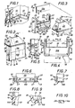
- la figure 11 est, suivant la flèche XI de la figure 3, et avec un arrachement local, une vue en élévation du réducteur que comporte également l'accessoire de dérivation suivant l'invention ;
- la figure 12 est une vue en coupe transversale de ce réducteur, suivant la ligne XII-XII de la figure 1 1 ;
- la figure 13 en est une vue de dessous, suivant la flèche XIII de la figure 11 ;
- la figure 14 en est une vue partielle en coupe suivant la ligne XIV-XIV de la figure 13 ;
- la figure 15 reprend, à échelle supérieure, le détail de la figure 11 repéré par un encart XV sur celle-ci ;
- la figure 16 reprend, à la même échelle que la précédente, le détail de la figure 14 repéré par un encart XVI sur celle-ci ;
- la figure 17 est, suivant la flèche XVII de la figure 18, une vue en plan de l'ensemble des pièces constitutives de l'accessoire de dérivation suivant l'invention, lorsque celui-ci est brut de moulage ;
- la figure 18 est une vue en coupe transversale de cet ensemble, suivant la ligne XVIII-XVIII de la figure 17 ;
- la figure 19 est une vue en perspective analogue à celle de la figure 1, pour une mise en oeuvre entre mur et plafond de l'accessoire de dérivation suivant l'invention ;
- la figure 20 est une vue en perspective analogue à celle de la figure 2, pour une variante de réalisation de cet accessoire de dérivation.
- Figure 1 is a perspective view illustrating the implementation on a wall of a bypass accessory according to the invention;
- Figure 2 is a larger scale, a perspective view of the bypass accessory according to the invention;
- Figure 3 is, with local cutaway, an exploded perspective view;
- Figure 4 is, according to arrow IV of Figure 3, an elevational view of the housing that includes this bypass accessory, the removable front wall portion that includes it being assumed removed;
- Figure 5 is a cross-sectional view of this housing, along the line VV of Figure 4;
- Figure 6 is a longitudinal sectional view along the line VI-VI of Figure 4;
- Figure 7 is another partial view, in longitudinal section, along the line VII-VII of Figure 4;
- Figure 8 shows, on a larger scale, the detail of Figure 5 identified by an insert VIII thereon;
- Figure 9 shows, on the same scale as the previous one, the detail of Figure 6 identified by an insert IX thereon;
- Figure 10 is, on the scale of Figure 9, a partial view in longitudinal section of the removable front wall portion of this housing, along line XX of Figure 3;
- Figure 11 is, along arrow XI of Figure 3, and with a local cutaway, an elevational view of the reducer that also includes the bypass accessory according to the invention;
- Figure 12 is a cross-sectional view of this reducer, along the line XII-XII of Figure 1 1;
- Figure 13 is a bottom view, along arrow XIII of Figure 11;
- Figure 14 is a partial sectional view along the line XIV-XIV of Figure 13;
- Figure 15 shows, on a larger scale, the detail of Figure 11 identified by an insert XV thereon;
- Figure 16 shows, on the same scale as the previous one, the detail of Figure 14 identified by an insert XVI thereon;
- Figure 17 is, according to arrow XVII of Figure 18, a plan view of all the component parts of the bypass accessory according to the invention, when the latter is unworked;
- Figure 18 is a cross-sectional view of this assembly, along the line XVIII-XVIII of Figure 17;
- Figure 19 is a perspective view similar to that of Figure 1, for an implementation between wall and ceiling of the bypass accessory according to the invention;
- Figure 20 is a perspective view similar to that of Figure 2, for an alternative embodiment of this bypass accessory.
Tel qu'illustré schématiquement sur les figures 1 et 19, il s'agit d'assurer la desserte d'un quelconque appareillage électrique, non représenté, à partir d'un conduit de câblage principal 10 contenant les conducteurs électriques 11 correspondants.As illustrated schematically in Figures 1 and 19, it is to provide service to any electrical equipment, not shown, from a
Dans la forme de mise en oeuvre plus particulièrement illustrée à la figure 1, ce conduit de câblage principal 10 court en plinthe à la base de murs 12, à proximité d'un plancher 13.In the embodiment more particularly illustrated in FIG. 1, this main wiring conduit 10 short in plinth at the base of
Il s'agit donc, pour la desserte de l'appareillage électrique concerné, d'assurer, à partir du conduit de câblage principal 10, et suivant un changement de direction qui se fait en pratique sensiblement perpendiculairement à celui-ci, l'établissement d'un conduit de câblage dérivé 10ʹ, propre au logement et à la protection des conducteurs électriques 11ʹ nécessaires à la desserte recherchée, eux-mêmes convenablement dérivés des conducteurs électriques 11 précédents.It is therefore a question, for serving the electrical equipment concerned, of ensuring, from the
La constitution des conduits de câblage 10, 10ʹ est bien connue par elle-même, et, ne relevant pas en soi de la présente invention, elle ne sera pas décrite en détail ici.The constitution of the
Il suffira d'indiquer que ces conduits de câblage 10, 10ʹ sont formés en pratique à l'aide de deux types de profilés, l'un formant un corps 14, 14ʹ, par lequel un tel conduit de câblage 10, 10ʹ est adapté à être fixé au mur 12 concerné, l'autre formant un couvercle 15, 15ʹ, adapté lui, à être rapporté, en pratique par simple encliquetage, sur le corps 14, 14ʹ correspondant.It will suffice to indicate that these
En pratique, la largeur, L, du conduit de câblage principal 10 est supérieure à celle, Lʹ, du conduit de câblage dérivé 10ʹ.In practice, the width, L, of the
Pour l'établissement du conduit de câblage dérivé 10ʹ, il est mis en oeuvre, suivant l'invention, un accessoire de dérivation 17.For the establishment of the
Suivant l'invention, cet accessoire de dérivation 17 comporte, d'une part, un boîtier 18, par lequel, tel que schématisé en traits interrompus à la figure 5, il est adapté à être disposé localement en saillie sur le corps 14 du conduit de câblage principal 10, en substitution à une portion correspondante du couvercle 15 de celui-ci, et qui, dépourvu de fond, et donc en forme générale de cloche, présente une paroi de façade 19 et trois parois latérales 20, 21, à savoir deux parois transversales 20 et une paroi longitudinale 21, et, d'autre pat, un réducteur 22, qui comporte lui-même une paroi de façade 23 et deux parois latérales 24, lesdites parois latérales 24 dudit réducteur 22 s'étendant en oblique entre deux ouvertures 25, 25ʹ, l'une de largeur L1 sensiblemet égale à l'écartement E des parois latérales transversales 20 du boîtier 18, pour adaptation à celui-ci, l'autre de largeur Lʹ1 inférieure à la précédente.According to the invention, this
En pratique, cette largeur Lʹ1 de l'ouverture de moindre largeur 25ʹ du réducteur 22, qui forme l'ouverture de sortie de celui-ci, et donc l'ouverture de sortie pour l'ensemble, et qui, comme l'ouverture de plus grande largeur 25, est de contour sensiblement quadrangulaire, est sensiblement égale à la largeur Lʹ du conduit de câblage dérivé 10ʹ, tout en étant légèrement supérieure à celle-ci.In practice, this width Lʹ1 of the opening of smaller width 25ʹ of the
Conjointement, le boîtier 18 a, transversalement, une hauteur H sensiblement égale à la largeur L du conduit de câblage principal 10.At the same time, the
Dans la forme de réalisation représentée sur les figures 1 à 19, le réducteur 22 forme une pièce distincte du boîtier 18, il est prévu, entre ledit réducteur 22 et les parois latérales transversales 20 dudit boîtier 18, à l'extrémité libre de celles-ci, c'est-à-dire à l'extrémité de ces parois latérales transversales opposée à la paroi latérale longitudinale 21 qu'elles encadrent, des moyens d'accouplement, détaillés ci-après, propres à permettre d'y rapporter de manière amovible ledit réducteur 22, et une portion 19A, au moins, de la paroi de façade 19 dudit boîtier 18, entre lesdites parois latérales transversales 20 de celui-ci, est elle-même amovible, avec, entre ladite portion de paroi de façade amovible 19A et lesdites parois latérales transversales 20, des moyens d'accouplement de même type que les précédents.In the embodiment shown in Figures 1 to 19, the
En pratique, la portion de paroi de façade amovible 19A que présente ainsi le boîtier 18 forme une simple plaquette de contour globalement quadrangulaire, et ses dimensions correspondent à celles de l'ouverture de moindre largeur 25ʹ du réducteur 22.In practice, the portion of the removable
Dans la forme de réalisation représentée, il subsiste, entre les parois latérales transversales 20 du boîtier 18, une portion de paroi de façade fixe 19B.In the embodiment shown, there remains, between the transverse
Mais, transversalement, c'est-à-dire suivant la hauteur H de ce boîtier 18, et tel que schématisé en traits interrompus à la figure 4, l'extension de cette portion de paroi de façade fixe 19B peut être plus ou moins étendue, suivant, précisément, l'extension de cette hauteur H.However, transversely, that is to say along the height H of this
Dans la forme de réalisation représentée, les moyens d'accouplement mis en oeuvre entre, d'une part, les parois latérales transversales 20 du boîtier 18, et, d'autre part, la portion de paroi de façade amovible 19A de celui-ci et le réducteur 22 sont des moyens de coulissement, lesdits moyens de coulissement comportant au moins une rainure sur l'une quelconque des pièces concernées, et au moins une nervure, complémentaire de ladite rainure, sur l'autre de celles-ci.In the embodiment shown, the coupling means used between, on the one hand, the
Dans la forme de réalisation représentée, il y a, ainsi, en saillie vers l'intérieur, pour chacune des deux parois latérales transversales 20 du boîtier 18, deux nervures 27, 28, l'une qui s'étend sensiblement dans l'alignement de la portion de paroid de façade fixe 19B subsistante, à mi-épaisseur par rapport à celle-ci, l'autre qui s'étend sensiblement perpendiculairement à la précédente, transversalement par rapport à la paroi latérale transversale 20 qu'elle affecte, à l'extrémité libre de celle-ci.In the embodiment shown, there is thus, projecting inwards, for each of the two transverse
Conjointement, pour la portion de paroi de façade amovible 19A, il y a, disposées dos à dos, chacune respectivement le long des deux bords transversaux opposés concernés de cette portion de paroi de façade amovible 19A, et sur toute la longueur de ceux-ci, deux rainures 29.Jointly, for the removable
Dans la forme de réalisation représentée, la portion de paroi de façade fixe 19B du boîtier 18 est par ailleurs bordée, le long de son bord libre, et en saillie sur sa face interne, par une baguette 30, qui fait également saillie en direction de l'extrémité libre des parois latérales transversales 20 de ce boîtier 18.In the embodiment shown, the fixed
Dans la forme de réalisation représentée, les parois latérales transversales 20 du boîtier 18 s'étendent légèrement en oblique par rapport à la paroi de façade 19 de celui-ci, et il en est de même pour sa paroi latérale longitudinale 21, en sorte que, dans son ensemble, ce boîtier 18 a une forme générale tronc-pyramidale.In the embodiment shown, the
De préférence, et tel que représenté, le boîtier 18 présen te, en saillie à la base de chacune de ses parois latérales transversales 20, au moins un crochet 32 propre à son crochetage sur les tronçons de couvercle 15 correspondants du conduit de câblage principal 10.Preferably, and as shown, the
Dans la forme de réalisation représentée, seul un tel crochet 32 est prévu pour chacune des parois latérales transversales 20, dans la zone médiane de celles-ci.In the embodiment shown, only such a
De préférence, également, et tel qu'également représenté, la paroi latérale longitudinale 21 du boîtier 18 se prolonge, sur une partie au moins de sa longueur, par un flasque 33.Preferably also, and as also shown, the
En pratique, celui-ci ne s'étend que sur une portion de longueur de cette paroi latérale longitudinale 21, ses extrémités étant chacune respectivement en retrait par rapport aux extrémités de celle-ci.In practice, the latter extends only over a portion of length of this
Enfin, dans la forme de réalisation représentée, le boîtier 18 présente, localement, en saillie vers le bas, parallèlement à sa paroi latérale longitudinale 21, à distance de celle-ci, au moins un ergot 35.Finally, in the embodiment shown, the
En pratique, dans la forme de réalisation représentée, deux ergots 35 sont ainsi prévus, et chacun d'eux forme le prolongement local d'une cloison 36 prévue, localement, en refend vers l'intérieur, en saillie sur la paroi latérale longitudinale 21, sensilement perpendiculairement à celle-ci.In practice, in the embodiment shown, two
La distance e séparant un tel ergot 35 de cette paroi latérale longitudinale 21 est faite légèrement supérieure à la dimension transversale correspondante des ailes latérales du corps 14 du conduit de câblage principal 10.The distance e separating such a
Dans la forme de réalisation représentée, le réducteur 22 est, comme le boîtier 18 précédent, dépourvu de fond.In the embodiment shown, the
En outre, dans cette forme de réalisation, la paroi de façade 23 de ce réducteur 22 s'étend elle aussi en oblique, en sorte que, dans son ensemble, ce réducteur 22 a lui aussi une forme générale tronc-pyramidale.In addition, in this embodiment, the
Du côté, au moins, de son ouverture de plus grande largeur 25, les parois latérales 24 du réducteur 22 ont une hauteur Hʹ1 supérieure à celle H1 des parois latérales 20, 21 du boîtier 18.On the side, at least, of its
En pratique, la différence entre ces hauteurs Hʹ1 et H1 est sensiblement égale à la hauteur, ou épaisseur, h du corps 14 du conduit de câblage principal 10.In practice, the difference between these heights Hʹ1 and H1 is substantially equal to the height, or thickness, h of the
Compte tenu de l'obliquité de sa paroi de façade 23, les parois latérales 24 du réducteur 22 ont, du côté de son ouverture de moindre largeur 25ʹ, une hauteur qui est inférieure à leur hauteur Hʹ1 du côté de l'ouverture de plus grande largeur 25, et qui, en pratique, est sensiblement égale à la hauteur h, le conduit de câblage dérivé 10ʹ ayant lui-même une hauteur qui, en pratique, est sensiblement égale à celle du conduit de câblage principal 10.Given the obliquity of its
Pour coopération avec les nervures 27 ou 28 du boîtier 18, il y a, pour le réducteur 22, disposées dos à dos, au voisinage, chacune respectivement, de l'extrémité de ses parois latérales 24, du côté de son ouverture de plus grande largeur 25, deux rainures 38.For cooperation with the
En pratique, ces rainures 38 sont formées sur des piédroits 39, qui, sur une partie de la hauteur des parois latérales 24 du réducteur 22, s'étendent en saillie sur la face interne de la paroi de façade 23 de celui-ci, à proximité de l'extrémité desdites parois latérales 24 correspondant à l'ouverture de plus grande largeur 25.In practice, these
Du côté de la paroi de façade 23, ces rainures 38 sont en pratique fermées transversalement par une lèvre défonçable 40 qui s'étend en continuité avec ladite paroi de façade 23, à niveau avec la surface extérieure de celle-ci.On the side of the
De préférence, et tel que représenté, les parois latérales 24 du réducteur 22 présentent, transversalement, de place en place, en correspondance de l'une à l'autre, et sur une partie au moins de leur hauteur correspondant à la hauteur h de l'ouverture de moindre largeur 25ʹ, des zones de moindre résistance 41, propres à permettre, par élimination d'une portion de ces par ois latérales 24, une augmentation de largeur Lʹ1 de ladite ouverture de moindre largeur 25ʹ.Preferably, and as shown, the
Dans la forme de réalisation représentée, trois zones de moindre résistance 41 sont ainsi prévues pour chacune des parois latérales 24 du réducteur 22, et, en pratique, elles résultent, chacune respectivement, de saignées, de section transversale triangulaire, ménagées sur la face interne de celles-ci.In the embodiment shown, three zones of
Ainsi qu'il est aisé de le comprendre, les diverses pièces ainsi constitutives de l'accessoire de dérivation 17 suivant l'invention peuvent avantageusement être réalisées en matière synthétique, par moulage de celle-ci.As is easy to understand, the various parts thus constituting the
De préférence, et tel qu'illustré sur les figures 17 et 18, ce moulage est fait simultanément, en sorte que, lorsqu'il est brut de moulage, les diverses pièces constituant l'accessoire de dérivation 17 suivant l'invention, à savoir son boîtier 18, la portion de paroi de façade amovible 19A de celui-ci, et son réducteur 22, sont attenantes deux à deux, avec, entre elles, des zones de moindre résistance.Preferably, and as illustrated in FIGS. 17 and 18, this molding is done simultaneously, so that, when it is molding raw, the various parts constituting the
Par exemple, et tel que représenté, la portion de paroi de façade amovible 19A s'étend à compter de l'extrémité libre des parois latérales transversales 20 du boîtier 18, à la base de celles-ci, et le réducteur 22 s'étend, lui, à compter de la tranche opposée de cette portion de paroi de façade amovible 19A.For example, and as shown, the removable
Pour la mise en oeuvre de l'accessoire de dérivation 17 suivant l'invention, il suffit, donc, de dissocier les unes des autres ces diverses pièces.For the implementation of the
Lorsque, tel que représenté à la figure 1, seul un changement de direction dans un plan est nécessaire, la portion de paroi de façade amovible 19A est utilisée, et, par les moyens d'accouplement que constituent avec les nervures 27 des parois latérales transversales 20 ses rainures 29, elle est mise en place, par simple coulissement, entre ces parois latérales transversales 20, en continuité avec la portion de paroi de façade fixe 19B, ce qui reconstitue dans son ensemble la paroi de façade 19 correspondante.When, as shown in FIG. 1, only a change of direction in a plane is necessary, the removable
Par les moyens d'accouplement que constituent conjointement, avec ses propres rainures 38, les nervures 28 des parois latérales transversales 20 du boîtier 18, le réducteur 22 est à son tour mis en place, par simple coulissement, sur ce boîtier 18.By the coupling means which, together with its
Il s'étend alors suivant une première orientation par rapport à celui-ci, pour laquelle il est sensiblement dans son prolongement latéral.It then extends in a first orientation relative to the latter, for which it is substantially in its lateral extension.
Les connexions nécessaires ayant été faites entre les conducteurs électriques 11ʹ dérivés et les conducteurs électriques principaux 11, l'accessoire de dérivation 17 suivant l'invention est mis en place sur l'ensemble.The necessary connections having been made between the 11ʹ derived electrical conductors and the main
Par son boîtier 18, il vient coiffer localement le corps 14 du conduit de câblage principal 10, tandis que, par son réducteur 22, il vient coiffer, conjointement, le conduit de câblage dérivé 10ʹ.Through its
Lors de sa mise en place sur le corps 14 du conduit de câblage principal 10, l'accessoire de dérivation 17 suivant l'invention vient coiffer, entre le flasque 33 prolongeant la paroi latérale longitudinale 21 de son boîtier 18 et les ergots 35 dont est muni à cet effet ce dernier, celle des ailes latérales de ce corps 14 qui est opposée au conduit de câblage dérivé 10ʹ, ce qui assure son maintien latérale par rapport à l'ensemble.When it is placed on the
En outre, lorsque des tronçons de courvercle 15 sont à leur tour mis en place sur le corps 14 du conduit de câblage principal 10, ces tronçons de couvercle 15 viennent recouvrir les crochets 32 que comporte le boîtier 18 de l'accessoire de dérivation 17 suivant l'invention, ce qui assure à son tour le maintien de celui-ci perpendiculairement à ce conduit de câblage principal 10.In addition, when the
Ainsi, l'accessoire de dérivation 17 se trouve convenablement assujetti, de lui-même, à l'ensemble.Thus, the
En outre, et ainsi qu'on l'aura compris, le volume que forme avantageusement son boîtier 18 au-dessus du corps 14 du conduit de câblag e principal 10 permet le raccordement des conducteurs électriques dérivés 11ʹ aux conducteurs électriques principaux 11 sans qu'il soit nécessaire d'appliquer une quelconque découpe à ce corps 14 pour le passage de ces conducteurs électriques dérivés 11ʹ.In addition, and as will be understood, the volume advantageously formed by its
Lorsque le changement de direction de la dérivation à établir s'accompagne d'un changement de plan, et c'est le cas par exemple au ras d'un plafond 45, figure 19, la portion de paroi de façade amovible 19A du boîtier 18 est éliminée, et il lui est substitué le réducteur 22, par engagement à coulissement de celui-ci, par ses rainures 38, sur les nervures 27 que présentent en saillie vers l'intérieur les parois latérales transversales 20 de ce boîtier 18.When the change of direction of the branch to be established is accompanied by a change of plane, and this is the case for example flush with a
En effet, comme déjà succinctement exposé ci-dessus, les dimensions de la portion de paroi de façade amovible 19A du boîtier 18 correspondent à celles de l'ouverture de plus grande largeur 25 du réducteur 22.In fact, as already succinctly explained above, the dimensions of the removable
Autrement dit, la longueur de cette portion de paroi de façade amovible 19A du boîtier 18, perpendiculairement à ses rainures 29, est sensiblement égale à la largeur L1 de cette ouverture de plus grande largeur 25 du réducteur 22, tandis que sa hauteur, suivant lesdites rainures 29, est sensiblement égale à la hauteur Hʹ1 de celle-ci.In other words, the length of this portion of removable
Quoi qu'il en soit, le réducteur 22 est alors rapporté sur le boîtier 18 suivant une deuxième orientation, qui, distincte de la première, s'étend sensiblement d'équerre par rapport à celle-ci, et pour laquelle il fait globalement saillie sur la paroi de façade 19 du boîtier 18.Anyway, the
Le changement de plan nécessaire est ainsi assuré.The necessary plan change is thus ensured.
En variante, et tel que représenté à la figure 20, lorsque le changement de direction de la dérivation à établir ne s'accompagne pas d'un tel changement de plan, il est possible de se satisfaire d'une réalisation monobloc de l'accessoire de dérivation 17 suivant l'invention.As a variant, and as shown in FIG. 20, when the change in direction of the branch to be established is not accompanied by such a change in plan, it is possible to be satisfied with a one-piece embodiment of the
Autrement dit, dans un tel cas, le réducteur de cet accessoire de dérivation 17 est d'un seul tenant avec son boîtier 18, l'ensemble ne formant qu'une seule et même pièce.In other words, in such a case, the reducer of this
Pour le reste, les dispositions de cette variante de réalisation sont du même type que les précédentes.For the rest, the provisions of this alternative embodiment are of the same type as the previous ones.
Bien entendu, la présente invention ne se limite pas aux formes de réalisation décrites et représentées, mais englobe toute variante d'exécution. Of course, the present invention is not limited to the embodiments described and shown, but encompasses any variant.
Claims (14)
Applications Claiming Priority (2)
| Application Number | Priority Date | Filing Date | Title |
|---|---|---|---|
| FR8614012A FR2605152B1 (en) | 1986-10-08 | 1986-10-08 | BYPASS ACCESSORY FOR WIRING DUCT |
| FR8614012 | 1986-10-08 |
Publications (2)
| Publication Number | Publication Date |
|---|---|
| EP0267079A1 true EP0267079A1 (en) | 1988-05-11 |
| EP0267079B1 EP0267079B1 (en) | 1993-03-17 |
Family
ID=9339672
Family Applications (1)
| Application Number | Title | Priority Date | Filing Date |
|---|---|---|---|
| EP19870402229 Expired - Lifetime EP0267079B1 (en) | 1986-10-08 | 1987-10-07 | Derivation accessory for a wiring conduit |
Country Status (4)
| Country | Link |
|---|---|
| EP (1) | EP0267079B1 (en) |
| DE (1) | DE3784840T2 (en) |
| ES (1) | ES2044965T3 (en) |
| FR (1) | FR2605152B1 (en) |
Cited By (5)
| Publication number | Priority date | Publication date | Assignee | Title |
|---|---|---|---|---|
| EP0753920A1 (en) * | 1995-07-12 | 1997-01-15 | Aparellaje Electrico, S.A. | A junction box for raceways for electrical conductors |
| EP0776078A1 (en) * | 1995-11-23 | 1997-05-28 | Legrand | Derivation accessory for an electrical profile, such as a wall-mounted cable duct |
| EP1005127A1 (en) * | 1998-11-27 | 2000-05-31 | Legrand | Holder for apparatus to be fastened alongside a channel with multipiece cover |
| US6663199B1 (en) * | 2000-03-24 | 2003-12-16 | Legrand | Housing for devices to be disposed along trunking, in particular electrical devices |
| EP3217496B1 (en) * | 2016-03-10 | 2022-12-14 | GGK GmbH & Co. KG | Cable duct branch |
Citations (2)
| Publication number | Priority date | Publication date | Assignee | Title |
|---|---|---|---|---|
| GB1199802A (en) * | 1967-03-15 | 1970-07-22 | Volex Electrical Products Ltd | Improvements relating to Electrical Surface Wiring |
| DE2060093A1 (en) * | 1970-12-07 | 1972-06-29 | Oberweimar Elektroinstallation | Branch or crossing device for foot and wall molding duct installation |
-
1986
- 1986-10-08 FR FR8614012A patent/FR2605152B1/en not_active Expired
-
1987
- 1987-10-07 DE DE19873784840 patent/DE3784840T2/en not_active Expired - Fee Related
- 1987-10-07 ES ES87402229T patent/ES2044965T3/en not_active Expired - Lifetime
- 1987-10-07 EP EP19870402229 patent/EP0267079B1/en not_active Expired - Lifetime
Patent Citations (2)
| Publication number | Priority date | Publication date | Assignee | Title |
|---|---|---|---|---|
| GB1199802A (en) * | 1967-03-15 | 1970-07-22 | Volex Electrical Products Ltd | Improvements relating to Electrical Surface Wiring |
| DE2060093A1 (en) * | 1970-12-07 | 1972-06-29 | Oberweimar Elektroinstallation | Branch or crossing device for foot and wall molding duct installation |
Cited By (11)
| Publication number | Priority date | Publication date | Assignee | Title |
|---|---|---|---|---|
| EP0753920A1 (en) * | 1995-07-12 | 1997-01-15 | Aparellaje Electrico, S.A. | A junction box for raceways for electrical conductors |
| ES2112168A1 (en) * | 1995-07-12 | 1998-03-16 | Aparellaje Electrico Sa | A junction box for raceways for electrical conductors |
| US5753856A (en) * | 1995-07-12 | 1998-05-19 | Aparellaje Electrico, S.A. | Junction box for raceways for electrical conductors |
| EP0776078A1 (en) * | 1995-11-23 | 1997-05-28 | Legrand | Derivation accessory for an electrical profile, such as a wall-mounted cable duct |
| FR2741754A1 (en) * | 1995-11-23 | 1997-05-30 | Legrand Sa | DERIVATION ACCESSORY FOR ELECTRICAL PROFILE, SUCH AS CHUTE, TO BE FITTED IN BAND |
| EP1005127A1 (en) * | 1998-11-27 | 2000-05-31 | Legrand | Holder for apparatus to be fastened alongside a channel with multipiece cover |
| FR2786616A1 (en) * | 1998-11-27 | 2000-06-02 | Legrand Sa | SUPPORT FOR APPARATUS ARRANGED ALONG A CHUTE WITH CANOPY IN MULTIPLE PARTS |
| US6350948B1 (en) | 1998-11-27 | 2002-02-26 | Legrand | Support with multipart trunking cover portion for equipment to be placed along trunking |
| AU759839B2 (en) * | 1998-11-27 | 2003-05-01 | Legrand | Support with multipart trunking cover portion for equipment to be placed along trunking |
| US6663199B1 (en) * | 2000-03-24 | 2003-12-16 | Legrand | Housing for devices to be disposed along trunking, in particular electrical devices |
| EP3217496B1 (en) * | 2016-03-10 | 2022-12-14 | GGK GmbH & Co. KG | Cable duct branch |
Also Published As
| Publication number | Publication date |
|---|---|
| EP0267079B1 (en) | 1993-03-17 |
| ES2044965T3 (en) | 1994-01-16 |
| DE3784840D1 (en) | 1993-04-22 |
| FR2605152A1 (en) | 1988-04-15 |
| DE3784840T2 (en) | 1993-06-24 |
| FR2605152B1 (en) | 1989-01-13 |
Similar Documents
| Publication | Publication Date | Title |
|---|---|---|
| EP1094581B1 (en) | Passage accessory for channel | |
| EP1133819B1 (en) | Apparatus box to be arranged along a wireway, in particular for electrical apparatus | |
| EP0267079B1 (en) | Derivation accessory for a wiring conduit | |
| FR2731496A1 (en) | CORNER CONNECTION DEVICE FOR DUCT WITH GUTTER BODY AND COVER, SUCH AS MOLDING, PLINTH OR CHUTE, ESPECIALLY FOR ELECTRICAL EQUIPMENT | |
| FR2758016A1 (en) | METHOD AND DEVICE FOR STRENGTHENING THE HOLDING ON A CHUTE OF ANY ACCESSORY TO BE FITTED BY NESTING ON THE BASE THEREOF | |
| EP0418152B1 (en) | Modular, especially electrical, device with a protective cover for reference marks | |
| EP0440556B1 (en) | Flush-mounted box with lateral extension, in particular for electrical apparatus | |
| EP1164675B1 (en) | Derivation accessory positionned at the junction of two cable channels | |
| EP1005127B1 (en) | Holder for apparatus to be fastened alongside a channel with multipiece cover | |
| FR2796771A1 (en) | INSULATION BOX FOR APPARATUS TO BE REPORTED ON THE BASE OF A CHUTE THROUGH A SUPPORT | |
| EP1164676A1 (en) | Mounting device for an electrical apparatus on a cable duct | |
| EP0875974B1 (en) | Thin wall flush mounted box with hinged tubing entries for electrical apparatus | |
| EP0721245A1 (en) | Apparatus support for a box partly embedded in a conduit, and method for carrying out the same | |
| FR2649253A1 (en) | Two-part mounting box, especially for an electrical apparatus | |
| FR2669175A1 (en) | Opening and reconfigurable box for electrical apparatus | |
| BE1005843A3 (en) | Box for electrical appliances, a base expansion cone and fitness. | |
| EP0923176A1 (en) | Jaw fastening accessory for flush mounted box and associated flush mounted box | |
| FR2662326A1 (en) | Cabinet for electrical apparatus, with external cladding having at least one removable plate | |
| EP0755175A1 (en) | Connecting device for casings for electrical equipment | |
| FR2781097A1 (en) | RECESSED BOX FOR DRY PARTITION WITH TIE-DOWN LEG (S) INITIALLY ON ONE HOLDER, ESPECIALLY FOR ELECTRICAL EQUIPMENT | |
| EP0964495B1 (en) | Flush mounted box with body and foot extending the box, especially for electrical apparatus | |
| EP0473483B1 (en) | Mounting box for electrical apparatus | |
| EP0475798B1 (en) | Modular mounting box for electrical apparatus | |
| WO2001014647A1 (en) | Stable tripod-type linking device, inserted between a receptacle and a lid, and resulting assembly | |
| EP0887903B1 (en) | V-shaped raceway base for corner or flush mounting |
Legal Events
| Date | Code | Title | Description |
|---|---|---|---|
| PUAI | Public reference made under article 153(3) epc to a published international application that has entered the european phase |
Free format text: ORIGINAL CODE: 0009012 |
|
| AK | Designated contracting states |
Kind code of ref document: A1 Designated state(s): BE DE ES GB IT NL |
|
| 17P | Request for examination filed |
Effective date: 19880926 |
|
| 17Q | First examination report despatched |
Effective date: 19910213 |
|
| GRAA | (expected) grant |
Free format text: ORIGINAL CODE: 0009210 |
|
| AK | Designated contracting states |
Kind code of ref document: B1 Designated state(s): BE DE ES GB IT NL |
|
| REF | Corresponds to: |
Ref document number: 3784840 Country of ref document: DE Date of ref document: 19930422 |
|
| GBT | Gb: translation of ep patent filed (gb section 77(6)(a)/1977) |
Effective date: 19930406 |
|
| ITF | It: translation for a ep patent filed |
Owner name: FUMERO BREVETTI S.N.C. |
|
| REG | Reference to a national code |
Ref country code: ES Ref legal event code: FG2A Ref document number: 2044965 Country of ref document: ES Kind code of ref document: T3 |
|
| PLBE | No opposition filed within time limit |
Free format text: ORIGINAL CODE: 0009261 |
|
| STAA | Information on the status of an ep patent application or granted ep patent |
Free format text: STATUS: NO OPPOSITION FILED WITHIN TIME LIMIT |
|
| 26N | No opposition filed | ||
| PGFP | Annual fee paid to national office [announced via postgrant information from national office to epo] |
Ref country code: BE Payment date: 19980824 Year of fee payment: 12 |
|
| PG25 | Lapsed in a contracting state [announced via postgrant information from national office to epo] |
Ref country code: BE Free format text: LAPSE BECAUSE OF NON-PAYMENT OF DUE FEES Effective date: 19991031 |
|
| BERE | Be: lapsed |
Owner name: PLANET WATTOHM Effective date: 19991031 |
|
| PGFP | Annual fee paid to national office [announced via postgrant information from national office to epo] |
Ref country code: NL Payment date: 20001031 Year of fee payment: 14 |
|
| REG | Reference to a national code |
Ref country code: GB Ref legal event code: IF02 |
|
| PG25 | Lapsed in a contracting state [announced via postgrant information from national office to epo] |
Ref country code: NL Free format text: LAPSE BECAUSE OF NON-PAYMENT OF DUE FEES Effective date: 20020501 |
|
| NLV4 | Nl: lapsed or anulled due to non-payment of the annual fee |
Effective date: 20020501 |
|
| PGFP | Annual fee paid to national office [announced via postgrant information from national office to epo] |
Ref country code: DE Payment date: 20051007 Year of fee payment: 19 |
|
| PGFP | Annual fee paid to national office [announced via postgrant information from national office to epo] |
Ref country code: ES Payment date: 20061016 Year of fee payment: 20 |
|
| PGFP | Annual fee paid to national office [announced via postgrant information from national office to epo] |
Ref country code: GB Payment date: 20061019 Year of fee payment: 20 |
|
| PGFP | Annual fee paid to national office [announced via postgrant information from national office to epo] |
Ref country code: IT Payment date: 20061031 Year of fee payment: 20 |
|
| PG25 | Lapsed in a contracting state [announced via postgrant information from national office to epo] |
Ref country code: DE Free format text: LAPSE BECAUSE OF NON-PAYMENT OF DUE FEES Effective date: 20070501 |
|
| REG | Reference to a national code |
Ref country code: GB Ref legal event code: PE20 |
|
| REG | Reference to a national code |
Ref country code: ES Ref legal event code: FD2A Effective date: 20071008 |
|
| PG25 | Lapsed in a contracting state [announced via postgrant information from national office to epo] |
Ref country code: ES Free format text: LAPSE BECAUSE OF EXPIRATION OF PROTECTION Effective date: 20071008 Ref country code: GB Free format text: LAPSE BECAUSE OF EXPIRATION OF PROTECTION Effective date: 20071006 |