EP0267079A1 - Abzweigungszubehör für Verkabelungsrohr - Google Patents
Abzweigungszubehör für Verkabelungsrohr Download PDFInfo
- Publication number
- EP0267079A1 EP0267079A1 EP87402229A EP87402229A EP0267079A1 EP 0267079 A1 EP0267079 A1 EP 0267079A1 EP 87402229 A EP87402229 A EP 87402229A EP 87402229 A EP87402229 A EP 87402229A EP 0267079 A1 EP0267079 A1 EP 0267079A1
- Authority
- EP
- European Patent Office
- Prior art keywords
- housing
- side walls
- front wall
- reducer
- accessory according
- Prior art date
- Legal status (The legal status is an assumption and is not a legal conclusion. Google has not performed a legal analysis and makes no representation as to the accuracy of the status listed.)
- Granted
Links
- 238000009795 derivation Methods 0.000 title description 3
- 238000000465 moulding Methods 0.000 claims abstract description 8
- 239000003638 chemical reducing agent Substances 0.000 claims description 39
- 230000008878 coupling Effects 0.000 claims description 10
- 238000010168 coupling process Methods 0.000 claims description 10
- 238000005859 coupling reaction Methods 0.000 claims description 10
- 238000006467 substitution reaction Methods 0.000 claims description 5
- 230000000295 complement effect Effects 0.000 claims description 2
- 229920002994 synthetic fiber Polymers 0.000 claims description 2
- 238000000926 separation method Methods 0.000 abstract 1
- 239000004020 conductor Substances 0.000 description 11
- 238000005192 partition Methods 0.000 description 2
- 230000006978 adaptation Effects 0.000 description 1
- 230000008030 elimination Effects 0.000 description 1
- 238000003379 elimination reaction Methods 0.000 description 1
- 230000014759 maintenance of location Effects 0.000 description 1
- 239000000725 suspension Substances 0.000 description 1
Images

Classifications
-
- H—ELECTRICITY
- H02—GENERATION; CONVERSION OR DISTRIBUTION OF ELECTRIC POWER
- H02G—INSTALLATION OF ELECTRIC CABLES OR LINES, OR OF COMBINED OPTICAL AND ELECTRIC CABLES OR LINES
- H02G3/00—Installations of electric cables or lines or protective tubing therefor in or on buildings, equivalent structures or vehicles
- H02G3/02—Details
- H02G3/08—Distribution boxes; Connection or junction boxes
- H02G3/10—Distribution boxes; Connection or junction boxes for surface mounting on a wall
- H02G3/105—Distribution boxes; Connection or junction boxes for surface mounting on a wall in association with a plinth, channel, raceway or similar
Definitions
- the present invention relates generally to wiring conduits, such as trunking, moldings, plinths or the like, of the type which, for example to be attached to a wall, are commonly used for housing and protection of electrical conductors.
- these profiles comprising a body, which generally has a U-shaped configuration, with a central part forming the sole and two lateral wings, and which can optionally be compartmentalized internally by longitudinal partitions, and a cover, which is adapted to be attached to such a body.
- the present invention relates more particularly to the establishment, from such a wiring conduit, or main wiring conduit, of a bypass, which, also implementing a wiring conduit, or derived wiring conduit, is suitable for serving any electrical equipment.
- This derivation involves a change of direction with respect to the main wiring conduit, in practice following a perpendicular to it.
- the change of direction of the bypass corresponding implies a change of plane, to go from the plane of the wall to that of the ceiling.
- a bypass accessory which, generally in a T shape, extends in practice substantially in the plane of a such cover, to restore the continuity thereof.
- the present invention generally relates to a provision advantageously allowing to get rid of any cut.
- a bypass accessory for wiring conduit such as trunking, molding, plinth or the like, characterized in that it comprises, on the one hand, a housing, by which it is adapted to be arranged locally projecting from the body of such a wiring duct, in substitution for a corresponding portion of the cover thereof, and which, devoid of bottom, has a front wall and three side walls, namely two transverse walls and a longitudinal wall, and, on the other hand, a reducer, which itself comprises a front wall and two side walls, said side walls of said reducer extending obliquely between two openings thereof, one of width substantially equal to the spacing of the transverse lateral walls of the housing, the other of width less than the previous one.
- the bypass accessory according to the invention is adapted to be superimposed, locally, by its housing, on the body of a wiring conduit, and, the volume formed by such a housing then communicating directly with the internal volume of such a wiring duct, since this box has no bottom, it is possible to pass the necessary electrical conductors, without there being any cut to be made to this wiring duct.
- the bypass accessory according to the invention is advantageously capable of ensuring by itself the reduction in width which always exists in practice between a main wiring conduit and the derived wiring conduit with the help of which a derivation is established from it.
- the reduction gear is in one piece with the housing, the assembly forming only one and the same part.
- the reduction gear forms a separate part of the housing, there is provided, between said reduction gear and the transverse lateral walls of said housing, at the free end thereof, coupling means specific to allow to removably bring therein said reducer, in a first orientation for which this reducer is substantially in the lateral extension of the housing, and at least a portion of the front wall of said housing, between the transverse lateral walls of the latter , is itself removable, with, between said removable front wall portion and said transverse side walls, coupling means of the same type as the previous ones, so that, in substitution for said removable front wall portion, the reducer can be attached to the housing in a second orientation, square with respect to the first, for which this reducer projects generally on the front wall from the case.
- bypass accessory according to the invention may, in this embodiment, be suitable as well, at the option of the users, for a change of direction in a plane, as is the case on a simple wall, which '' to a change of direction accompanied by a change of plan, as is the case for example when moving from a wall to a ceiling.
- this main wiring conduit 10 short in plinth at the base of walls 12, near a floor 13.
- these wiring conduits 10, 10 ⁇ are formed in practice using two types of profiles, one forming a body 14, 14 ⁇ , by which such a wiring conduit 10, 10 ⁇ is adapted to be fixed to the wall 12 concerned, the other forming a cover 15, 15 ⁇ , adapted to it, to be attached, in practice by simple snap-fastening, on the corresponding body 14, 14 ⁇ .
- the width, L, of the main wiring duct 10 is greater than that, L ⁇ , of the branched wiring duct 10 ⁇ .
- a branching accessory 17 is used, according to the invention.
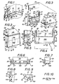
- this bypass accessory 17 comprises, on the one hand, a housing 18, by which, as shown schematically in broken lines in Figure 5, it is adapted to be arranged locally projecting from the body 14 of the conduit main wiring 10, replacing a corresponding portion of the cover 15 thereof, and which, devoid of bottom, and therefore in the general shape of a bell, has a front wall 19 and three side walls 20, 21, namely two transverse walls 20 and a longitudinal wall 21, and, on the other hand, a reducer 22, which itself has a front wall 23 and two side walls 24, said side walls 24 of said reducer 22 extending obliquely between two openings 25, 25 ⁇ , one of width L1 sensiblemet equal to the spacing E of the transverse side walls 20 of the housing 18, for adaptation thereto, the other of width L ⁇ 1 less than the previous one.
- this width L ⁇ 1 of the opening of smaller width 25 ⁇ of the reducer 22, which forms the outlet opening thereof, and therefore the outlet opening for the assembly, and which, like the opening of greater width 25, is of substantially quadrangular contour, is substantially equal to the width L ⁇ of the branched wiring conduit 10 ⁇ , while being slightly greater than this.
- the box 18 has, transversely, a height H substantially equal to the width L of the main wiring duct 10.
- the reducer 22 forms a separate part of the housing 18, there is provided, between said reducer 22 and the transverse side walls 20 of said housing 18, at the free end thereof ci, that is to say at the end of these transverse lateral walls opposite to the longitudinal lateral wall 21 which they frame, coupling means, detailed below, suitable for enabling them to be attached in such a way removable said reducer 22, and a portion 19A, at least, of the front wall 19 of said housing 18, between said transverse side walls 20 thereof, is itself removable, with, between said removable front wall portion 19A and said transverse side walls 20, coupling means of the same type as the previous ones.
- the portion of the removable front wall 19A that the housing 18 thus presents forms a simple plate with a generally quadrangular outline, and its dimensions correspond to those of the narrower opening 25 ⁇ of the reducer 22.
- the coupling means used between, on the one hand, the transverse side walls 20 of the housing 18, and, on the other hand, the removable front wall portion 19A thereof and the reduction gear 22 are sliding means, said sliding means comprising at least one groove on any one of the parts concerned, and at least one rib, complementary to said groove, on the other of these.
- the fixed front wall portion 19B of the housing 18 is also bordered, along its free edge, and projecting on its internal face, by a strip 30, which also projects in the direction of the free end of the transverse lateral walls 20 of this housing 18.
- the transverse side walls 20 of the housing 18 extend slightly obliquely with respect to the front wall 19 of the latter, and the same is true for its longitudinal side wall 21, so that , as a whole, this housing 18 has a general truncated pyramid shape.
- the housing 18 presents, projecting from the base of each of its transverse lateral walls 20, at least one hook 32 suitable for hooking it onto the corresponding cover sections 15 of the main wiring duct 10.
- the longitudinal side wall 21 of the housing 18 is extended, over at least part of its length, by a flange 33.
- the latter extends only over a portion of length of this longitudinal side wall 21, its ends each being respectively set back relative to the ends of the latter.
- the housing 18 has, locally, projecting downwards, parallel to its longitudinal side wall 21, at a distance from the latter, at least one lug 35.
- two lugs 35 are thus provided, and each of them forms the local extension of a partition 36 provided, locally, slitting inwards, projecting from the longitudinal side wall 21 , sensibly perpendicular to it.
- the reduction gear 22 is, like the previous housing 18, devoid of bottom.
- this reducer 22 also extends obliquely, so that, as a whole, this reducer 22 also has a general truncated pyramid shape.
- the side walls 24 of the reduction gear 22 have a height H ⁇ 1 greater than that H1 of the side walls 20, 21 of the housing 18.
- the difference between these heights H ⁇ 1 and H1 is substantially equal to the height, or thickness, h of the body 14 of the main wiring duct 10.
- the side walls 24 of the reducer 22 have, on the side of its opening of smaller width 25 ⁇ , a height which is less than their height H ⁇ 1 on the side of the opening of larger width 25, and which, in practice, is substantially equal to the height h , the branched wiring duct 10 ⁇ itself having a height which, in practice, is substantially equal to that of the main wiring duct 10.
- these grooves 38 are formed on piers 39, which, over part of the height of the side walls 24 of the reducer 22, protrude on the internal face of the front wall 23 thereof, at proximity of the end of said side walls 24 corresponding to the widest opening 25.
- these grooves 38 are in practice closed transversely by a knockout lip 40 which extends in continuity with said front wall 23, level with the external surface thereof.
- the side walls 24 of the reducer 22 have, transversely, from place to place, in correspondence with one another, and over at least part of their height corresponding to the height h of the opening of lesser width 25 ⁇ , zones of lesser resistance 41, capable of allowing, by elimination of a portion of these by lateral elements 24, an increase in width L ⁇ 1 of said opening of lesser width 25 ⁇ .
- three zones of least resistance 41 are thus provided for each of the side walls 24 of the reducer 22, and, in practice, they each result respectively from grooves, of triangular cross section, formed on the internal face. of these.
- the various parts thus constituting the bypass accessory 17 according to the invention can advantageously be made of synthetic material, by molding thereof.
- this molding is done simultaneously, so that, when it is molding raw, the various parts constituting the bypass accessory 17 according to the invention, namely its housing 18, the removable front wall portion 19A thereof, and its reducer 22, are contiguous in pairs, with, between them, zones of least resistance.
- the removable front wall portion 19A extends from the free end of the transverse side walls 20 of the housing 18, at the base thereof, and the reducer 22 extends , him, from the opposite edge of this portion of removable front wall 19A.
- bypass accessory 17 For the implementation of the bypass accessory 17 according to the invention, it suffices, therefore, to separate these various parts from one another.
- the removable front wall portion 19A is used, and, by the coupling means which constitute with the ribs 27 of the transverse lateral walls 20 its grooves 29, it is put in place, by simple sliding, between these transverse lateral walls 20, in continuity with the portion of fixed front wall 19B, which reconstitutes as a whole the corresponding front wall 19.
- the bypass accessory 17 When it is placed on the body 14 of the main wiring duct 10, the bypass accessory 17 according to the invention comes to cap between the flange 33 extending the longitudinal side wall 21 of its housing 18 and the pins 35 of which is provided for this purpose the latter, that of the lateral wings of this body 14 which is opposite to the derivative wiring duct 10 ⁇ , which ensures its lateral retention relative to the assembly.
- cover sections 15 when the cover sections 15 are in turn placed on the body 14 of the main wiring duct 10, these cover sections 15 cover the hooks 32 that comprise the housing 18 of the following branch accessory 17 the invention, which in turn ensures that it is held perpendicular to this main wiring conduit 10.
- bypass accessory 17 is suitably secured, by itself, to the assembly.
- the volume advantageously formed by its housing 18 above the body 14 of the main wiring conduit 10 allows the connection of the derivative electrical conductors 11 ⁇ to the conductors main electrical 11 without the need to apply any cutout to this body 14 for the passage of these derivative electrical conductors 11 ⁇ .
- the dimensions of the removable front wall portion 19A of the housing 18 correspond to those of the wider opening 25 of the reducer 22.
- the length of this portion of removable front wall 19A of the housing 18, perpendicular to its grooves 29, is substantially equal to the width L1 of this wider opening 25 of the reducer 22, while its height, according to said grooves 29, is substantially equal to the height H ⁇ 1 thereof.
- the reducer 22 is then attached to the housing 18 in a second orientation, which, distinct from the first, extends substantially square with respect thereto, and for which it projects generally on the front wall 19 of the housing 18.
- the reducer of this bypass accessory 17 is in one piece with its housing 18, the assembly forming only one and the same part.
Landscapes
- Engineering & Computer Science (AREA)
- Architecture (AREA)
- Civil Engineering (AREA)
- Structural Engineering (AREA)
- Details Of Indoor Wiring (AREA)
Applications Claiming Priority (2)
| Application Number | Priority Date | Filing Date | Title |
|---|---|---|---|
| FR8614012A FR2605152B1 (fr) | 1986-10-08 | 1986-10-08 | Accessoire de derivation pour conduit de cablage |
| FR8614012 | 1986-10-08 |
Publications (2)
| Publication Number | Publication Date |
|---|---|
| EP0267079A1 true EP0267079A1 (de) | 1988-05-11 |
| EP0267079B1 EP0267079B1 (de) | 1993-03-17 |
Family
ID=9339672
Family Applications (1)
| Application Number | Title | Priority Date | Filing Date |
|---|---|---|---|
| EP19870402229 Expired - Lifetime EP0267079B1 (de) | 1986-10-08 | 1987-10-07 | Abzweigungszubehör für Verkabelungsrohr |
Country Status (4)
| Country | Link |
|---|---|
| EP (1) | EP0267079B1 (de) |
| DE (1) | DE3784840T2 (de) |
| ES (1) | ES2044965T3 (de) |
| FR (1) | FR2605152B1 (de) |
Cited By (5)
| Publication number | Priority date | Publication date | Assignee | Title |
|---|---|---|---|---|
| EP0753920A1 (de) * | 1995-07-12 | 1997-01-15 | Aparellaje Electrico, S.A. | Abzweigdose für Leitungen zur Aufnahme von elektrischen Kabeln |
| EP0776078A1 (de) * | 1995-11-23 | 1997-05-28 | Legrand | Abzweigungszubehör für Elektroprofil, wie Wandkabelrinne |
| EP1005127A1 (de) * | 1998-11-27 | 2000-05-31 | Legrand | Geräteträgereinrichtung Einzubringen auf einen Kabelkanalseite mit mehrteiliger Abdeckung |
| US6663199B1 (en) * | 2000-03-24 | 2003-12-16 | Legrand | Housing for devices to be disposed along trunking, in particular electrical devices |
| EP3217496B1 (de) * | 2016-03-10 | 2022-12-14 | GGK GmbH & Co. KG | Kabelkanalabzweigung |
Citations (2)
| Publication number | Priority date | Publication date | Assignee | Title |
|---|---|---|---|---|
| GB1199802A (en) * | 1967-03-15 | 1970-07-22 | Volex Electrical Products Ltd | Improvements relating to Electrical Surface Wiring |
| DE2060093A1 (de) * | 1970-12-07 | 1972-06-29 | Oberweimar Elektroinstallation | Abzweig- oder Kreuzungseinrichtung fuer Fuss- und Wandleistenkanalinstallation |
-
1986
- 1986-10-08 FR FR8614012A patent/FR2605152B1/fr not_active Expired
-
1987
- 1987-10-07 ES ES87402229T patent/ES2044965T3/es not_active Expired - Lifetime
- 1987-10-07 DE DE19873784840 patent/DE3784840T2/de not_active Expired - Fee Related
- 1987-10-07 EP EP19870402229 patent/EP0267079B1/de not_active Expired - Lifetime
Patent Citations (2)
| Publication number | Priority date | Publication date | Assignee | Title |
|---|---|---|---|---|
| GB1199802A (en) * | 1967-03-15 | 1970-07-22 | Volex Electrical Products Ltd | Improvements relating to Electrical Surface Wiring |
| DE2060093A1 (de) * | 1970-12-07 | 1972-06-29 | Oberweimar Elektroinstallation | Abzweig- oder Kreuzungseinrichtung fuer Fuss- und Wandleistenkanalinstallation |
Cited By (11)
| Publication number | Priority date | Publication date | Assignee | Title |
|---|---|---|---|---|
| EP0753920A1 (de) * | 1995-07-12 | 1997-01-15 | Aparellaje Electrico, S.A. | Abzweigdose für Leitungen zur Aufnahme von elektrischen Kabeln |
| ES2112168A1 (es) * | 1995-07-12 | 1998-03-16 | Aparellaje Electrico Sa | Caja de conexion para canalizaciones electricas. |
| US5753856A (en) * | 1995-07-12 | 1998-05-19 | Aparellaje Electrico, S.A. | Junction box for raceways for electrical conductors |
| EP0776078A1 (de) * | 1995-11-23 | 1997-05-28 | Legrand | Abzweigungszubehör für Elektroprofil, wie Wandkabelrinne |
| FR2741754A1 (fr) * | 1995-11-23 | 1997-05-30 | Legrand Sa | Accessoire de derivation pour profile electrique, tel que goulotte, a disposer en bandeau |
| EP1005127A1 (de) * | 1998-11-27 | 2000-05-31 | Legrand | Geräteträgereinrichtung Einzubringen auf einen Kabelkanalseite mit mehrteiliger Abdeckung |
| FR2786616A1 (fr) * | 1998-11-27 | 2000-06-02 | Legrand Sa | Support pour appareillage a disposer le long d'une goulotte avec auvent en plusieurs parties |
| US6350948B1 (en) | 1998-11-27 | 2002-02-26 | Legrand | Support with multipart trunking cover portion for equipment to be placed along trunking |
| AU759839B2 (en) * | 1998-11-27 | 2003-05-01 | Legrand | Support with multipart trunking cover portion for equipment to be placed along trunking |
| US6663199B1 (en) * | 2000-03-24 | 2003-12-16 | Legrand | Housing for devices to be disposed along trunking, in particular electrical devices |
| EP3217496B1 (de) * | 2016-03-10 | 2022-12-14 | GGK GmbH & Co. KG | Kabelkanalabzweigung |
Also Published As
| Publication number | Publication date |
|---|---|
| EP0267079B1 (de) | 1993-03-17 |
| FR2605152A1 (fr) | 1988-04-15 |
| FR2605152B1 (fr) | 1989-01-13 |
| DE3784840D1 (de) | 1993-04-22 |
| DE3784840T2 (de) | 1993-06-24 |
| ES2044965T3 (es) | 1994-01-16 |
Similar Documents
| Publication | Publication Date | Title |
|---|---|---|
| EP1094581B1 (de) | Durchführungszubehör für Kabelkanal | |
| EP1133819B1 (de) | Gerätegehäuse zum auf einen kabelkanalseite insbesondere für elektrisches gerät einbringen | |
| EP0734107A1 (de) | Winkelzubehörverbindungselement für Elektrokanal und Winkelzubehör dafür | |
| EP0267079B1 (de) | Abzweigungszubehör für Verkabelungsrohr | |
| FR2731496A1 (fr) | Dispositif de raccordement d'angle pour conduit a corps en gouttiere et couvercle tel que moulure, plinthe ou goulotte, notamment pour appareillage electrique | |
| FR2758016A1 (fr) | Procede et dispositif pour affermir le maintien sur une goulotte d'un quelconque accessoire a rapporter par emboitement sur le socle de celle-ci | |
| EP0418152B1 (de) | Modulares, insbesondere elektrisches, Gerät mit Schutzdeckel für Hinweisschilder | |
| EP0440556B1 (de) | Einbaudose mit Seitenverlängerung, insbesondere für elektrisches Gerät | |
| EP1164675B1 (de) | Abzweigungszubehör zur Positionierung zwischen zwei Kabelrinnen | |
| EP1005127B1 (de) | Geräteträgereinrichtung seitlich anzubringen an einem Kabelkanal mit mehrteiliger Abdeckung | |
| FR2796771A1 (fr) | Boitier d'isolation pour appareil a rapporter sur le socle d'une goulotte par l'intermediaire d'un support | |
| EP0414616A1 (de) | Klammerartige Abdeckungsverbindung für eine Leiste oder Rinne | |
| EP1164676A1 (de) | Vorrichtung zur Befestigung eines elektrischen Geräts auf einem Kabelkanal | |
| EP0875974B1 (de) | Unterputzdose in einer Wand geringer Dicke für elektrisches Gerät mit einer Leitungsklappeinführung | |
| FR2729255A1 (fr) | Support d'appareillage a boite semi-encastree a travers un conduit, et son procede de mise en oeuvre | |
| BE1005858A3 (fr) | Coffret pour appareils electriques, a habillage exterieur presentant au moins une plaque amovible. | |
| FR2649253A1 (fr) | Boite d'encastrement en deux parties, notamment pour appareillage electrique | |
| EP0964494B1 (de) | Abzweigungszubehör für Elektroinstallation sowie Elektroinstallation | |
| FR2669175A1 (fr) | Boitier ouvrant et modulable pour appareillage(s) electrique(s). | |
| BE1005843A3 (fr) | Coffret pour appareils electriques, a embase d'extension et cornet d'adaptation. | |
| EP0923176A1 (de) | Greifhalter für einbaudose und einbaudose | |
| EP0755175A1 (de) | Verbindungsvorrrichtung für Gerätegehäuse | |
| FR2781097A1 (fr) | Boite d'encastrement pour cloison seche a patte(s) de serrage initialement d'un seul tenant, notamment pour appareillage electrique | |
| EP0964495B1 (de) | Unterputzdose mit Körper und Fuss als Doseverlängerung insbesondere für elektrische Geräte | |
| EP0473483B1 (de) | Befestigungsgehäuse für elektrisches Gerät |
Legal Events
| Date | Code | Title | Description |
|---|---|---|---|
| PUAI | Public reference made under article 153(3) epc to a published international application that has entered the european phase |
Free format text: ORIGINAL CODE: 0009012 |
|
| AK | Designated contracting states |
Kind code of ref document: A1 Designated state(s): BE DE ES GB IT NL |
|
| 17P | Request for examination filed |
Effective date: 19880926 |
|
| 17Q | First examination report despatched |
Effective date: 19910213 |
|
| GRAA | (expected) grant |
Free format text: ORIGINAL CODE: 0009210 |
|
| AK | Designated contracting states |
Kind code of ref document: B1 Designated state(s): BE DE ES GB IT NL |
|
| REF | Corresponds to: |
Ref document number: 3784840 Country of ref document: DE Date of ref document: 19930422 |
|
| GBT | Gb: translation of ep patent filed (gb section 77(6)(a)/1977) |
Effective date: 19930406 |
|
| ITF | It: translation for a ep patent filed | ||
| REG | Reference to a national code |
Ref country code: ES Ref legal event code: FG2A Ref document number: 2044965 Country of ref document: ES Kind code of ref document: T3 |
|
| PLBE | No opposition filed within time limit |
Free format text: ORIGINAL CODE: 0009261 |
|
| STAA | Information on the status of an ep patent application or granted ep patent |
Free format text: STATUS: NO OPPOSITION FILED WITHIN TIME LIMIT |
|
| 26N | No opposition filed | ||
| PGFP | Annual fee paid to national office [announced via postgrant information from national office to epo] |
Ref country code: BE Payment date: 19980824 Year of fee payment: 12 |
|
| PG25 | Lapsed in a contracting state [announced via postgrant information from national office to epo] |
Ref country code: BE Free format text: LAPSE BECAUSE OF NON-PAYMENT OF DUE FEES Effective date: 19991031 |
|
| BERE | Be: lapsed |
Owner name: PLANET WATTOHM Effective date: 19991031 |
|
| PGFP | Annual fee paid to national office [announced via postgrant information from national office to epo] |
Ref country code: NL Payment date: 20001031 Year of fee payment: 14 |
|
| REG | Reference to a national code |
Ref country code: GB Ref legal event code: IF02 |
|
| PG25 | Lapsed in a contracting state [announced via postgrant information from national office to epo] |
Ref country code: NL Free format text: LAPSE BECAUSE OF NON-PAYMENT OF DUE FEES Effective date: 20020501 |
|
| NLV4 | Nl: lapsed or anulled due to non-payment of the annual fee |
Effective date: 20020501 |
|
| PGFP | Annual fee paid to national office [announced via postgrant information from national office to epo] |
Ref country code: DE Payment date: 20051007 Year of fee payment: 19 |
|
| PGFP | Annual fee paid to national office [announced via postgrant information from national office to epo] |
Ref country code: ES Payment date: 20061016 Year of fee payment: 20 |
|
| PGFP | Annual fee paid to national office [announced via postgrant information from national office to epo] |
Ref country code: GB Payment date: 20061019 Year of fee payment: 20 |
|
| PGFP | Annual fee paid to national office [announced via postgrant information from national office to epo] |
Ref country code: IT Payment date: 20061031 Year of fee payment: 20 |
|
| PG25 | Lapsed in a contracting state [announced via postgrant information from national office to epo] |
Ref country code: DE Free format text: LAPSE BECAUSE OF NON-PAYMENT OF DUE FEES Effective date: 20070501 |
|
| REG | Reference to a national code |
Ref country code: GB Ref legal event code: PE20 |
|
| REG | Reference to a national code |
Ref country code: ES Ref legal event code: FD2A Effective date: 20071008 |
|
| PG25 | Lapsed in a contracting state [announced via postgrant information from national office to epo] |
Ref country code: ES Free format text: LAPSE BECAUSE OF EXPIRATION OF PROTECTION Effective date: 20071008 Ref country code: GB Free format text: LAPSE BECAUSE OF EXPIRATION OF PROTECTION Effective date: 20071006 |