EP2042462B1 - Elevator apparatus - Google Patents
Elevator apparatus Download PDFInfo
- Publication number
- EP2042462B1 EP2042462B1 EP09150612A EP09150612A EP2042462B1 EP 2042462 B1 EP2042462 B1 EP 2042462B1 EP 09150612 A EP09150612 A EP 09150612A EP 09150612 A EP09150612 A EP 09150612A EP 2042462 B1 EP2042462 B1 EP 2042462B1
- Authority
- EP
- European Patent Office
- Prior art keywords
- hoistway
- car
- counterweight
- disposed
- driving machine
- Prior art date
- Legal status (The legal status is an assumption and is not a legal conclusion. Google has not performed a legal analysis and makes no representation as to the accuracy of the status listed.)
- Expired - Lifetime
Links
Images

Classifications
-
- B—PERFORMING OPERATIONS; TRANSPORTING
- B66—HOISTING; LIFTING; HAULING
- B66B—ELEVATORS; ESCALATORS OR MOVING WALKWAYS
- B66B11/00—Main component parts of lifts in, or associated with, buildings or other structures
- B66B11/0035—Arrangement of driving gear, e.g. location or support
- B66B11/0045—Arrangement of driving gear, e.g. location or support in the hoistway
-
- B—PERFORMING OPERATIONS; TRANSPORTING
- B66—HOISTING; LIFTING; HAULING
- B66B—ELEVATORS; ESCALATORS OR MOVING WALKWAYS
- B66B11/00—Main component parts of lifts in, or associated with, buildings or other structures
- B66B11/0065—Roping
- B66B11/008—Roping with hoisting rope or cable operated by frictional engagement with a winding drum or sheave
Definitions
- the present invention relates to an elevator apparatus in which a driving machine is disposed in an upper portion inside a hoistway.
- Document EP 1 018 480 A2 discloses an elevator system having a vertically oriented drive sheave at an upper end of the shaft.
- the counterweight is provided along a rear side of the elevator car.
- the present invention aims to solve the above problems and an object of the present invention is to provide an elevator apparatus enabling increases in height dimensions of a hoistway to be suppressed while disposing a driving machine in an upper portion inside the hoistway.
- an elevator apparatus including: a hoistway having a hoistway wall; a driving machine disposed in an upper portion inside the hoistway, having: a driving machine body; and a drive sheave rotated by the driving machine body around a rotating shaft extending in a vertical direction; a main rope having a car end portion and a counterweight end portion secured to an upper portion inside the hoistway, an intermediate portion being wound around the drive sheave; a car having mutually opposite first and second side surfaces, being suspended inside the hoistway by the main rope between the drive sheave and the car end portion so as to be raised and lowered inside the hoistway by the driving machine; a counterweight disposed between the first side surface and the hoistway wall, being suspended inside the hoistway by the main rope between the drive sheave and the counterweight end portion so as to be raised and lowered inside the hoistway by the driving machine; a car return sheave disposed in an upper portion inside the hoistway and around which the main rope is
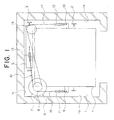
- Figure 1 is a general plan showing an elevator apparatus according to Embodiment 1
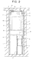
- Figure 2 is a side elevation showing the elevator apparatus in Figure 1 .
- a hoistway 1 has hoistway walls 1a to 1c.
- a pair of car guide rails 2 and a pair of counterweight guide rails 3 are installed inside the hoistway 1.
- a car 4 is guided by the car guide rails 2 so as to be raised and lowered inside the hoistway 1.
- a counterweight 5 is guided by the counterweight guide rails 3 so as to be raised and lowered inside the hoistway 1.
- the counterweight 5 is disposed behind the car 4.
- a driving machine (a hoisting machine) 6 for raising and lowering the car 4 and the counterweight 5 is disposed horizontally in an upper portion inside the hoistway 1.
- the driving machine 6 is disposed above a first corner portion of a rear portion of the car 4.
- the driving machine 6 also has a driving machine body 7 and a drive sheave 8.
- the drive sheave 8 is rotated by the driving machine body 7 around a rotating shaft extending in a vertical direction.
- First and second main rope connection portions 9 and 10 are disposed on both sides of a lower portion of the car 4.
- the first and second main rope connection portions 9 and 10 are disposed symmetrically about the position of the center of gravity of the car 4 so as to be positioned on opposite sides of the car 4 in a vertical plane of projection.
- First and second car return sheaves 11 and 12 are disposed in an upper portion inside the hoistway 1 above the first and second main rope connection portions 9 and 10.
- a counterweight return sheave 13 is disposed in an upper portion inside the hoistway 1 above the counterweight 5. These return sheaves 11 to 13 are each rotatable around a rotating shaft extending in a horizontal direction.
- the first and second car return sheaves 11 and 12 are disposed between the hoistway walls 1a and 1b and a region projected vertically from the car 4, and the first and second car return sheaves 11 and 12 are parallel to each of the hoistway walls 1a and 1b.
- a direction-changing pulley 14 rotatable around a rotating shaft extending in a vertical direction is disposed above a second corner portion of the rear portion of the car 4.
- a main rope group 15 for suspending the car 4 and the counterweight 5 inside the hoistway 1 is wound around the drive sheave 8.
- the main rope group 15 has a plurality of first main ropes 16 and a plurality of second main ropes 17. These main ropes 16 and 17 are each composed of a synthetic fiber rope.
- First end portions of the first main ropes 16 pass through the first car return sheave 11 and are connected to the first main rope connection portion 9, and second end portions pass through the counterweight return sheave 13 and are connected to an upper portion of the counterweight 5.
- First end portions of the second main ropes 17 pass through the direction-changing pulley 14 and the second car return sheave 12 and are connected to the second main rope connection portion 10, and second end portions pass through the counterweight return sheave 13 and are connected to an upper portion of the counterweight 5.
- first main ropes 16 and the second main ropes 17 connected to the counterweight 5 are branched off in two directions at the drive sheave 8 and connected to the car 4.
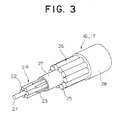
- FIG 3 is a perspective showing a construction of the first and second main ropes 16 and 17 from Figure 1 .
- an inner strand layer 24 having a plurality of inner strands 22 and filler strands 23 disposed in gaps between these inner strands 22 is disposed around a core wire 21.
- Each of the inner strands 22 is composed of a plurality of aramid fibers and an impregnating material such as polyurethane or the like.
- the filler strands 23 are composed of a polyamide, for example.
- An outer strand layer 26 having a plurality of outer strands 25 is disposed around an outer circumference of the inner strand layer 24.
- Each of the outer strands 25 is composed of a plurality of aramid fibers and an impregnating material such as polyurethane or the like in a similar manner to the inner strands 22.
- a protective coating layer 28 is also disposed on an outer circumferential portion of the outer strand layer 26.
- the car 4 and the counterweight 5 are suspended inside the hoistway 1 by a plurality of main ropes 12 having the above construction.
- the synthetic fiber rope has a high coefficient of friction compared to a steel rope and is superior in flexibility.
- the car 4 can be stably suspended at its center of gravity.
- first and second main rope connection portions 9 and 10 are disposed on both sides of the car 4, it is not necessary to dispose connection portions for the main rope group 15 on an upper portion of the car 4. Consequently, the dimensions of the upper portion of the car 4 can be reduced, enabling suppression of increases in height dimensions of the hoistway 1 while disposing the driving machine 6 in the upper portion inside the hoistway 1.
- first and second car return sheaves 11 and 12 are disposed between the hoistway walls 1a and 1b and the region projected vertically from the car 4, the first and second car return sheaves 11 and 12 do not come into contact with the car 4. Consequently, increases in height dimensions of the hoistway 1 can be suppressed.
- Increases in height dimensions of the hoistway 1 can be further suppressed if lower ends of the first and second car return sheaves 11 and 12 are disposed so as to be lower than a car ceiling position when the car 4 is positioned at a maximum point of upward motion, .
- the equipment can be disposed utilizing space inside the hoistway 1 effectively and can be easily adapted to changes in frontage dimensions and depth dimensions of the car 4.
- first and second main ropes 16 and 17 composed of a synthetic fiber rope having a high coefficient of friction and superior flexibility are used, diameters of the drive sheave 8, the return sheaves 11 to 13, and the pulley 14 can be reduced, enabling suppression of increases in height dimensions of the hoistway 1.
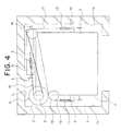
- Figure 4 is a general plan showing an elevator apparatus according to Embodiment 2
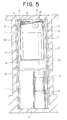
- Figure 5 is a side elevation showing the elevator apparatus in Figure 4 .
- a first direction-changing pulley 18 rotatable around a rotating shaft extending in a vertical direction is disposed above the second corner portion of the rear portion of the car 4.
- the first and second main ropes 16 and 17 are wound around the first direction-changing pulley 18 and are branched off at the first direction-changing pulley 18.
- a second direction-changing pulley 19 rotatable around a rotating shaft extending in a vertical direction is disposed between the first direction-changing pulley 18 and the first car return sheave 11.
- the first main ropes 16 pass from the first direction-changing pulley 18, through the second direction-changing pulley 19 and the first car return sheave 11, and are connected to the first main rope connection portion 9.
- the rest of the construction is similar to that of Embodiment 1.
- Figure 6 is a general plan showing an elevator apparatus according to Embodiment 3 of the present invention
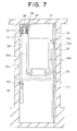
- Figure 7 is a side elevation showing the elevator apparatus in Figure 6 .
- a hoistway 31 has hoistway walls 31a to 31c.
- a pair of car guide rails 32 and a pair of counterweight guide rails 33 are installed inside the hoistway 31.
- a car 34 is guided by the car guide rails 32 so as to be raised and lowered inside the hoistway 31.
- the car 34 has mutually opposite first and second side surfaces 34a and 34b.
- a counterweight 35 is guided by the counterweight guide rails 33 so as to be raised and lowered inside the hoistway 31.
- the counterweight 35 is disposed between the first side surface 34a of the car 34 and the hoistway walls 31a.
- a driving machine (a hoisting machine) 36 for raising and lowering the car 34 and the counterweight 35 is disposed horizontally in an upper portion inside the hoistway 31.
- the driving machine 36 is disposed above a first corner portion of a rear portion of the car 34.
- the driving machine 36 also has a driving machine body 37 and a drive sheave 38.
- the drive sheave 38 is rotated by the driving machine body 37 around a rotating shaft extending in a vertical direction.
- the car 34 and the counterweight 35 are suspended inside the hoistway 31 by main ropes 39 composed of a synthetic fiber rope.
- the main ropes 39 have car end portions 39a and counterweight end portions 39b secured to car and counterweight rope fastener portions 40a and 40b in an upper portion inside the hoistway 31, intermediate portions being wound around the drive sheave 38.
- the construction of the main ropes 39 is similar to that in Figure 3 .
- the car 34 is suspended inside the hoistway 31 by the main ropes 39 between the drive sheave 38 and the car end portions 39a.
- the counterweight 35 is suspended inside the hoistway 31 by the main ropes 39 between the drive sheave 38 and the counterweight end portions 39b.
- a car return sheave 41 for guiding the main ropes 39 from the drive sheave 38 to the car 34 and a counterweight return sheave 42 for guiding the main ropes 39 from the drive sheave 38 to the counterweight 35 are disposed in upper portions inside the hoistway 31.
- the car and counterweight return sheaves 41 and 42 are disposed above a space between the first side surface 34a of the car 34 and the hoistway wall 31a.
- a pair of rotatable car suspension sheaves 43 around which the main ropes 39 are wound are disposed on a lower portion of the car 34.
- a rotatable counterweight suspension sheave 44 around which the main ropes 39 are wound is disposed on an upper portion of the counterweight 35.
Description
- The present invention relates to an elevator apparatus in which a driving machine is disposed in an upper portion inside a hoistway.
- Conventional machine-roomless elevators of a type in which a driving machine is disposed in a pit in a hoistway are often adopted. However, in this type, countermeasures against flooding of the pit have been required.
- In contrast to this, in a type in which the driving machine is disposed in an upper portion inside the hoistway, particularly in the case of one-to-one roping, if the position of the center of gravity of a car is to be suspended, it is necessary to ensure proportionate space between the car and a top portion of the hoistway since the main ropes are connected to an upper beam of the car, increasing the height dimensions of the hoistway.
- Document
EP 1 018 480 A2 discloses an elevator system having a vertically oriented drive sheave at an upper end of the shaft. The counterweight is provided along a rear side of the elevator car. - The present invention aims to solve the above problems and an object of the present invention is to provide an elevator apparatus enabling increases in height dimensions of a hoistway to be suppressed while disposing a driving machine in an upper portion inside the hoistway.
- According to the present invention, there is provided an elevator apparatus including: a hoistway having a hoistway wall; a driving machine disposed in an upper portion inside the hoistway, having: a driving machine body; and a drive sheave rotated by the driving machine body around a rotating shaft extending in a vertical direction; a main rope having a car end portion and a counterweight end portion secured to an upper portion inside the hoistway, an intermediate portion being wound around the drive sheave; a car having mutually opposite first and second side surfaces, being suspended inside the hoistway by the main rope between the drive sheave and the car end portion so as to be raised and lowered inside the hoistway by the driving machine; a counterweight disposed between the first side surface and the hoistway wall, being suspended inside the hoistway by the main rope between the drive sheave and the counterweight end portion so as to be raised and lowered inside the hoistway by the driving machine; a car return sheave disposed in an upper portion inside the hoistway and around which the main rope is wound, for guiding the main rope from the drive sheave to the car; and a counterweight return sheave disposed in an upper portion inside the hoistway and around which the main rope is wound, for guiding the main rope from the drive sheave to the counterweight, wherein the driving machine is disposed above a corner portion of a rear portion of the car on a side near the counterweight, and the car and counterweight return sheaves are disposed above a space between the first side surface and the hoistway wall.
-
-
Figure 1 is a general plan showing an elevator apparatus according to Embodiment 1 (not part of this invention); -
Figure 2 is a side elevation showing the elevator apparatus inFigure 1 ; -
Figure 3 is a perspective showing a construction of first and second main ropes fromFigure 1 ; -
Figure 4 is a general plan showing an elevator apparatus according to Embodiment 2 (not part of this invention); -
Figure 5 is a side elevation showing the elevator apparatus inFigure 4 ; -
Figure 6 is a general plan showing an elevator apparatus according toEmbodiment 3 of the present invention; and -
Figure 7 is a side elevation showing the elevator apparatus inFigure 6 . - A preferred embodiment (Embodiment 3) of the present invention will be explained below with reference to the drawings. Further, additional embodiments (embodiment 1 and 2) are also mentioned below.
-
Figure 1 is a general plan showing an elevator apparatus according to Embodiment 1 , andFigure 2 is a side elevation showing the elevator apparatus inFigure 1 . - In the figures, a hoistway 1 has hoistway walls 1a to 1c. A pair of
car guide rails 2 and a pair ofcounterweight guide rails 3 are installed inside the hoistway 1. Acar 4 is guided by thecar guide rails 2 so as to be raised and lowered inside the hoistway 1. Acounterweight 5 is guided by thecounterweight guide rails 3 so as to be raised and lowered inside the hoistway 1. Thecounterweight 5 is disposed behind thecar 4. - A driving machine (a hoisting machine) 6 for raising and lowering the
car 4 and thecounterweight 5 is disposed horizontally in an upper portion inside the hoistway 1. The drivingmachine 6 is disposed above a first corner portion of a rear portion of thecar 4. The drivingmachine 6 also has a drivingmachine body 7 and adrive sheave 8. Thedrive sheave 8 is rotated by the drivingmachine body 7 around a rotating shaft extending in a vertical direction. - First and second main
rope connection portions car 4. The first and second mainrope connection portions car 4 so as to be positioned on opposite sides of thecar 4 in a vertical plane of projection. - First and second car return sheaves 11 and 12 are disposed in an upper portion inside the hoistway 1 above the first and second main
rope connection portions counterweight return sheave 13 is disposed in an upper portion inside the hoistway 1 above thecounterweight 5. These return sheaves 11 to 13 are each rotatable around a rotating shaft extending in a horizontal direction. - The first and second car return sheaves 11 and 12 are disposed between the
hoistway walls 1a and 1b and a region projected vertically from thecar 4, and the first and second car return sheaves 11 and 12 are parallel to each of thehoistway walls 1a and 1b. A direction-changingpulley 14 rotatable around a rotating shaft extending in a vertical direction is disposed above a second corner portion of the rear portion of thecar 4. - A
main rope group 15 for suspending thecar 4 and thecounterweight 5 inside the hoistway 1 is wound around thedrive sheave 8. Themain rope group 15 has a plurality of firstmain ropes 16 and a plurality of secondmain ropes 17. Thesemain ropes - First end portions of the first
main ropes 16 pass through the firstcar return sheave 11 and are connected to the first mainrope connection portion 9, and second end portions pass through thecounterweight return sheave 13 and are connected to an upper portion of thecounterweight 5. First end portions of the secondmain ropes 17 pass through the direction-changingpulley 14 and the secondcar return sheave 12 and are connected to the second mainrope connection portion 10, and second end portions pass through thecounterweight return sheave 13 and are connected to an upper portion of thecounterweight 5. - In other words, the first
main ropes 16 and the secondmain ropes 17 connected to thecounterweight 5 are branched off in two directions at thedrive sheave 8 and connected to thecar 4. -
Figure 3 is a perspective showing a construction of the first and secondmain ropes Figure 1 . In the figure, aninner strand layer 24 having a plurality ofinner strands 22 andfiller strands 23 disposed in gaps between theseinner strands 22 is disposed around acore wire 21. Each of theinner strands 22 is composed of a plurality of aramid fibers and an impregnating material such as polyurethane or the like. Thefiller strands 23 are composed of a polyamide, for example. - An
outer strand layer 26 having a plurality ofouter strands 25 is disposed around an outer circumference of theinner strand layer 24. Each of theouter strands 25 is composed of a plurality of aramid fibers and an impregnating material such as polyurethane or the like in a similar manner to theinner strands 22. - A friction-reducing
coating layer 27 for preventing abrasion of thestrands strands drive sheave 11, etc., is disposed between theinner strand layer 24 and theouter strand layer 26. Aprotective coating layer 28 is also disposed on an outer circumferential portion of theouter strand layer 26. - The
car 4 and thecounterweight 5 are suspended inside the hoistway 1 by a plurality ofmain ropes 12 having the above construction. The synthetic fiber rope has a high coefficient of friction compared to a steel rope and is superior in flexibility. - In an elevator apparatus of this kind, because the
main rope group 15 is distributed into the first and secondmain ropes car 4 is suspended by the first and second mainrope connection portions car 4 can be stably suspended at its center of gravity. - Furthermore, since the first and second main
rope connection portions car 4, it is not necessary to dispose connection portions for themain rope group 15 on an upper portion of thecar 4. Consequently, the dimensions of the upper portion of thecar 4 can be reduced, enabling suppression of increases in height dimensions of the hoistway 1 while disposing the drivingmachine 6 in the upper portion inside the hoistway 1. - In addition, because the first and second car return sheaves 11 and 12 are disposed between the
hoistway walls 1a and 1b and the region projected vertically from thecar 4, the first and second car return sheaves 11 and 12 do not come into contact with thecar 4. Consequently, increases in height dimensions of the hoistway 1 can be suppressed. - Increases in height dimensions of the hoistway 1 can be further suppressed if lower ends of the first and second car return sheaves 11 and 12 are disposed so as to be lower than a car ceiling position when the
car 4 is positioned at a maximum point of upward motion, . - Furthermore, since the
counterweight 5 is disposed behind thecar 4, the drivingmachine 6 is disposed above the first corner portion of the rear portion of thecar 4, and the direction-changingpulley 14 is disposed above the second corner portion of the rear portion of thecar 4, the equipment can be disposed utilizing space inside the hoistway 1 effectively and can be easily adapted to changes in frontage dimensions and depth dimensions of thecar 4. - Because first and second
main ropes drive sheave 8, the return sheaves 11 to 13, and thepulley 14 can be reduced, enabling suppression of increases in height dimensions of the hoistway 1. -
Figure 4 is a general plan showing an elevator apparatus according toEmbodiment 2 , andFigure 5 is a side elevation showing the elevator apparatus inFigure 4 . - In the figures, a first direction-changing
pulley 18 rotatable around a rotating shaft extending in a vertical direction is disposed above the second corner portion of the rear portion of thecar 4. The first and secondmain ropes pulley 18 and are branched off at the first direction-changingpulley 18. - A second direction-changing
pulley 19 rotatable around a rotating shaft extending in a vertical direction is disposed between the first direction-changingpulley 18 and the firstcar return sheave 11. The firstmain ropes 16 pass from the first direction-changingpulley 18, through the second direction-changingpulley 19 and the firstcar return sheave 11, and are connected to the first mainrope connection portion 9. The rest of the construction is similar to that of Embodiment 1. - In an elevator apparatus of this kind, since the first and second
main ropes pulley 18, in addition to effects similar to those of Embodiment 1, winding angles of the first and secondmain ropes drive sheave 8 can be made the same, and sufficient winding angles can be achieved. -
Figure 6 is a general plan showing an elevator apparatus according toEmbodiment 3 of the present invention, andFigure 7 is a side elevation showing the elevator apparatus inFigure 6 . - In the figures, a
hoistway 31 hashoistway walls 31a to 31c. A pair ofcar guide rails 32 and a pair ofcounterweight guide rails 33 are installed inside thehoistway 31. Acar 34 is guided by thecar guide rails 32 so as to be raised and lowered inside thehoistway 31. Thecar 34 has mutually opposite first and second side surfaces 34a and 34b. - A
counterweight 35 is guided by thecounterweight guide rails 33 so as to be raised and lowered inside thehoistway 31. Thecounterweight 35 is disposed between the first side surface 34a of thecar 34 and thehoistway walls 31a. - A driving machine (a hoisting machine) 36 for raising and lowering the
car 34 and thecounterweight 35 is disposed horizontally in an upper portion inside thehoistway 31. The drivingmachine 36 is disposed above a first corner portion of a rear portion of thecar 34. The drivingmachine 36 also has a drivingmachine body 37 and adrive sheave 38. Thedrive sheave 38 is rotated by the drivingmachine body 37 around a rotating shaft extending in a vertical direction. - The
car 34 and thecounterweight 35 are suspended inside thehoistway 31 bymain ropes 39 composed of a synthetic fiber rope. Themain ropes 39 havecar end portions 39a and counterweight endportions 39b secured to car and counterweightrope fastener portions 40a and 40b in an upper portion inside thehoistway 31, intermediate portions being wound around thedrive sheave 38. The construction of themain ropes 39 is similar to that inFigure 3 . - The
car 34 is suspended inside thehoistway 31 by themain ropes 39 between thedrive sheave 38 and thecar end portions 39a. Thecounterweight 35 is suspended inside thehoistway 31 by themain ropes 39 between thedrive sheave 38 and thecounterweight end portions 39b. - A
car return sheave 41 for guiding themain ropes 39 from thedrive sheave 38 to thecar 34 and acounterweight return sheave 42 for guiding themain ropes 39 from thedrive sheave 38 to thecounterweight 35 are disposed in upper portions inside thehoistway 31. The car and counterweight returnsheaves car 34 and thehoistway wall 31a. - A pair of rotatable car suspension sheaves 43 around which the
main ropes 39 are wound are disposed on a lower portion of thecar 34. A rotatablecounterweight suspension sheave 44 around which themain ropes 39 are wound is disposed on an upper portion of thecounterweight 35. - In an elevator apparatus of this kind, since the car and counterweight return
sheaves car 34 and thehoistway wall 31a in a vertical plane of projection, planar dimensions of thehoistway 31 can be reduced. Furthermore, winding angles of themain ropes 39 onto thedrive sheave 38 can be sufficiently ensured.
Claims (2)
- An elevator apparatus comprising:a hoistway (31) having a hoistway wall (31a to 31c);a driving machine (36) disposed in an upper portion inside said hoistway (31), having:a driving machine body (37); anda drive sheave (38) rotated by said driving machine body (37) arounda rotating shaft extending in a vertical direction;a main rope (39) having a car end portion and a counterweight end portion secured to an upper portion inside said hoistway (31), an intermediate portion being wound around said drive sheave (38);a car (34) having mutually opposite first and second side surfaces (34a, 34b), being suspended inside said hoistway (31) by said main rope (39) between said drive sheave (38) and said car end portion (39a) so as to be raised and lowered inside said hoistway (31) by said driving machine (36);a counterweight (35) being suspended inside said hoistway (31) by said main rope (39) between said drive sheave (38) and said counterweight end portion (39b) so as to be raised and lowered inside said hoistway (31) by said driving machine (36);a car return sheave (41) disposed in an upper portion inside said hoistway (31) and around which said main rope (39) is wound, for guiding said main rope (39) from said drive sheave (38) to said car (34); anda counterweight return sheave (42) disposed in an upper portion inside said hoistway (31) and around which said main rope (39) is wound, for guiding said main rope (39) from said drive sheave (38) to said counterweight (35),characterized in that the counterweight (35) is disposed between said first side surface (34a) of the car (34) and said hoistway wall (31a), and in thatsaid driving machine (36) is disposed above a corner portion of a rear portion of said car (34) on a side near said counterweight (35), and said car and counterweight return sheaves (41, 42) are disposed above a space between said first side surface (34a) and said hoistway wall (31a).
- The elevator apparatus according to Claim 1, wherein said main rope (39) is composed of a synthetic fiber rope.
Applications Claiming Priority (2)
| Application Number | Priority Date | Filing Date | Title |
|---|---|---|---|
| EP00957123A EP1319627B1 (en) | 2000-09-12 | 2000-09-12 | Elevator device |
| PCT/JP2000/006230 WO2002022486A1 (en) | 2000-09-12 | 2000-09-12 | Elevator device |
Related Parent Applications (2)
| Application Number | Title | Priority Date | Filing Date |
|---|---|---|---|
| EP00957123.3 Division | 2000-09-12 | ||
| EP00957123A Division EP1319627B1 (en) | 2000-09-12 | 2000-09-12 | Elevator device |
Publications (2)
| Publication Number | Publication Date |
|---|---|
| EP2042462A1 EP2042462A1 (en) | 2009-04-01 |
| EP2042462B1 true EP2042462B1 (en) | 2011-05-18 |
Family
ID=11736454
Family Applications (2)
| Application Number | Title | Priority Date | Filing Date |
|---|---|---|---|
| EP00957123A Expired - Lifetime EP1319627B1 (en) | 2000-09-12 | 2000-09-12 | Elevator device |
| EP09150612A Expired - Lifetime EP2042462B1 (en) | 2000-09-12 | 2000-09-12 | Elevator apparatus |
Family Applications Before (1)
| Application Number | Title | Priority Date | Filing Date |
|---|---|---|---|
| EP00957123A Expired - Lifetime EP1319627B1 (en) | 2000-09-12 | 2000-09-12 | Elevator device |
Country Status (5)
| Country | Link |
|---|---|
| EP (2) | EP1319627B1 (en) |
| JP (1) | JPWO2002022486A1 (en) |
| CN (1) | CN1178844C (en) |
| DE (1) | DE60043516D1 (en) |
| WO (1) | WO2002022486A1 (en) |
Families Citing this family (17)
| Publication number | Priority date | Publication date | Assignee | Title |
|---|---|---|---|---|
| CN1220618C (en) * | 2002-06-10 | 2005-09-28 | 三菱电机株式会社 | Elevator |
| EP1586525B1 (en) * | 2003-01-23 | 2013-01-02 | Mitsubishi Denki Kabushiki Kaisha | Elevator equipment |
| EP1602612A4 (en) * | 2003-03-10 | 2009-08-05 | Mitsubishi Electric Corp | Elevator apparatus |
| DE60333795D1 (en) * | 2003-03-12 | 2010-09-23 | Mitsubishi Electric Corp | LIFT DEVICE |
| DE10325937B4 (en) * | 2003-06-07 | 2005-06-23 | Schmitt Aufzüge GmbH | Elevator with a rope-driven cabin |
| EP1693329A4 (en) * | 2003-12-11 | 2011-07-06 | Mitsubishi Electric Corp | Elevator apparatus |
| WO2005080250A1 (en) * | 2004-02-19 | 2005-09-01 | Mitsubishi Denki Kabushiki Kaisha | Machine room-less elevator |
| US20070045053A1 (en) * | 2004-04-28 | 2007-03-01 | Mitsubishi Denki Kabushiki Kaisha | Elevator apparatus |
| EP1754679A4 (en) | 2004-06-07 | 2012-06-06 | Mitsubishi Electric Corp | Elevator apparatus |
| WO2006033146A1 (en) * | 2004-09-22 | 2006-03-30 | Mitsubishi Denki Kabushiki Kaisha | Elevator apparatus |
| CN100542931C (en) * | 2005-03-04 | 2009-09-23 | 三菱电机株式会社 | Lift appliance |
| KR100752860B1 (en) * | 2005-12-28 | 2007-08-29 | 미쓰비시덴키 가부시키가이샤 | Elevator apparatus |
| KR100804886B1 (en) * | 2006-02-06 | 2008-02-20 | 미쓰비시덴키 가부시키가이샤 | Elevator apparatus |
| DE102006044669A1 (en) | 2006-02-09 | 2008-04-03 | Aufzugteile Bt Gmbh | Machine roomless propulsion lift |
| KR100804887B1 (en) * | 2007-10-12 | 2008-02-20 | 미쓰비시덴키 가부시키가이샤 | Elevator apparatus |
| CN104192673A (en) * | 2014-03-18 | 2014-12-10 | 永大电梯设备(中国)有限公司 | Elevator device without machine room |
| CN113003366B (en) * | 2021-02-01 | 2024-01-30 | 泰州威迈机电科技有限公司 | Traction device with elevator traction steel wire rope slip detection device |
Family Cites Families (6)
| Publication number | Priority date | Publication date | Assignee | Title |
|---|---|---|---|---|
| JPS62197672U (en) * | 1986-06-03 | 1987-12-16 | ||
| BR9500779A (en) * | 1994-03-02 | 1995-10-24 | Inventio Ag | Cable as a support medium for elevators |
| CA2169431C (en) * | 1995-03-06 | 2005-07-12 | Claudio De Angelis | Equipment for recognising when synthetic fibre cables are ripe for being discarded |
| ES2227012T3 (en) * | 1996-11-11 | 2005-04-01 | Inventio Ag | ELEVATOR INSTALLATION WITH MOTOR UNIT DISPOSED IN THE ELEVATOR BOX. |
| US6247557B1 (en) * | 1998-04-28 | 2001-06-19 | Kabushiki Kaisha Toshiba | Traction type elevator apparatus |
| JP4191331B2 (en) * | 1999-01-08 | 2008-12-03 | 三菱電機株式会社 | Elevator equipment |
-
2000
- 2000-09-12 EP EP00957123A patent/EP1319627B1/en not_active Expired - Lifetime
- 2000-09-12 DE DE60043516T patent/DE60043516D1/en not_active Expired - Lifetime
- 2000-09-12 EP EP09150612A patent/EP2042462B1/en not_active Expired - Lifetime
- 2000-09-12 WO PCT/JP2000/006230 patent/WO2002022486A1/en active Application Filing
- 2000-09-12 CN CNB008154066A patent/CN1178844C/en not_active Expired - Fee Related
- 2000-09-12 JP JP2002526687A patent/JPWO2002022486A1/en active Pending
Also Published As
| Publication number | Publication date |
|---|---|
| EP1319627B1 (en) | 2009-12-09 |
| CN1178844C (en) | 2004-12-08 |
| DE60043516D1 (en) | 2010-01-21 |
| WO2002022486A1 (en) | 2002-03-21 |
| EP2042462A1 (en) | 2009-04-01 |
| EP1319627A1 (en) | 2003-06-18 |
| JPWO2002022486A1 (en) | 2004-01-22 |
| CN1387491A (en) | 2002-12-25 |
| EP1319627A4 (en) | 2008-09-03 |
Similar Documents
| Publication | Publication Date | Title |
|---|---|---|
| EP2042462B1 (en) | Elevator apparatus | |
| EP1329412B1 (en) | Elevator device | |
| EP1302430B1 (en) | Elevator device | |
| EA005334B1 (en) | Machine-room-less traction sheave elevator | |
| US6619433B1 (en) | Elevator system using minimal building space | |
| EP1327596B1 (en) | Elevator device | |
| US20060016641A1 (en) | Elevator roping arrangement | |
| EP1396457B1 (en) | Elevator device | |
| EP1312573B1 (en) | Elevator device | |
| EP1602612A1 (en) | Elevator apparatus | |
| EP1512652B1 (en) | Elevator | |
| EP1316526A1 (en) | Elevator device | |
| EP1602613A1 (en) | Counterbalancing self-running elevator | |
| EP1314680B1 (en) | Elevator device | |
| KR100636870B1 (en) | Elevator device | |
| EP1586525B1 (en) | Elevator equipment | |
| EP1544150A1 (en) | Elevator equipment | |
| KR100735338B1 (en) | Elevator | |
| EP1736431B1 (en) | Elevator apparatus | |
| JPWO2004101419A1 (en) | Elevator equipment | |
| KR100804886B1 (en) | Elevator apparatus | |
| KR100691667B1 (en) | Elevator device | |
| KR100804887B1 (en) | Elevator apparatus | |
| JP2008280182A (en) | Elevator device | |
| WO2002020389A1 (en) | Elevator device |
Legal Events
| Date | Code | Title | Description |
|---|---|---|---|
| PUAI | Public reference made under article 153(3) epc to a published international application that has entered the european phase |
Free format text: ORIGINAL CODE: 0009012 |
|
| AC | Divisional application: reference to earlier application |
Ref document number: 1319627 Country of ref document: EP Kind code of ref document: P |
|
| AK | Designated contracting states |
Kind code of ref document: A1 Designated state(s): CH DE FR LI NL |
|
| 17P | Request for examination filed |
Effective date: 20090805 |
|
| 17Q | First examination report despatched |
Effective date: 20091014 |
|
| AKX | Designation fees paid |
Designated state(s): CH DE FR LI NL |
|
| GRAP | Despatch of communication of intention to grant a patent |
Free format text: ORIGINAL CODE: EPIDOSNIGR1 |
|
| GRAS | Grant fee paid |
Free format text: ORIGINAL CODE: EPIDOSNIGR3 |
|
| GRAA | (expected) grant |
Free format text: ORIGINAL CODE: 0009210 |
|
| REG | Reference to a national code |
Ref country code: CH Ref legal event code: EP |
|
| REG | Reference to a national code |
Ref country code: DE Ref legal event code: R096 Ref document number: 60045998 Country of ref document: DE Effective date: 20110630 |
|
| REG | Reference to a national code |
Ref country code: NL Ref legal event code: VDEP Effective date: 20110518 |
|
| PG25 | Lapsed in a contracting state [announced via postgrant information from national office to epo] |
Ref country code: NL Free format text: LAPSE BECAUSE OF FAILURE TO SUBMIT A TRANSLATION OF THE DESCRIPTION OR TO PAY THE FEE WITHIN THE PRESCRIBED TIME-LIMIT Effective date: 20110518 |
|
| PLBE | No opposition filed within time limit |
Free format text: ORIGINAL CODE: 0009261 |
|
| STAA | Information on the status of an ep patent application or granted ep patent |
Free format text: STATUS: NO OPPOSITION FILED WITHIN TIME LIMIT |
|
| 26N | No opposition filed |
Effective date: 20120221 |
|
| REG | Reference to a national code |
Ref country code: CH Ref legal event code: PL |
|
| REG | Reference to a national code |
Ref country code: DE Ref legal event code: R097 Ref document number: 60045998 Country of ref document: DE Effective date: 20120221 |
|
| REG | Reference to a national code |
Ref country code: FR Ref legal event code: ST Effective date: 20120531 |
|
| PG25 | Lapsed in a contracting state [announced via postgrant information from national office to epo] |
Ref country code: LI Free format text: LAPSE BECAUSE OF NON-PAYMENT OF DUE FEES Effective date: 20110930 Ref country code: CH Free format text: LAPSE BECAUSE OF NON-PAYMENT OF DUE FEES Effective date: 20110930 |
|
| PG25 | Lapsed in a contracting state [announced via postgrant information from national office to epo] |
Ref country code: FR Free format text: LAPSE BECAUSE OF NON-PAYMENT OF DUE FEES Effective date: 20110930 |
|
| REG | Reference to a national code |
Ref country code: DE Ref legal event code: R084 Ref document number: 60045998 Country of ref document: DE Effective date: 20140326 |
|
| PGFP | Annual fee paid to national office [announced via postgrant information from national office to epo] |
Ref country code: DE Payment date: 20180828 Year of fee payment: 19 |
|
| REG | Reference to a national code |
Ref country code: DE Ref legal event code: R119 Ref document number: 60045998 Country of ref document: DE |
|
| PG25 | Lapsed in a contracting state [announced via postgrant information from national office to epo] |
Ref country code: DE Free format text: LAPSE BECAUSE OF NON-PAYMENT OF DUE FEES Effective date: 20200401 |