EP2042452B1 - Vorrichtung zum Abtragen von ineinander verkeilten, versetzt angeordneten Gitterroste - Google Patents
Vorrichtung zum Abtragen von ineinander verkeilten, versetzt angeordneten Gitterroste Download PDFInfo
- Publication number
- EP2042452B1 EP2042452B1 EP08300272A EP08300272A EP2042452B1 EP 2042452 B1 EP2042452 B1 EP 2042452B1 EP 08300272 A EP08300272 A EP 08300272A EP 08300272 A EP08300272 A EP 08300272A EP 2042452 B1 EP2042452 B1 EP 2042452B1
- Authority
- EP
- European Patent Office
- Prior art keywords
- rack
- racks
- lifting
- robot
- rings
- Prior art date
- Legal status (The legal status is an assumption and is not a legal conclusion. Google has not performed a legal analysis and makes no representation as to the accuracy of the status listed.)
- Active
Links
- 230000015572 biosynthetic process Effects 0.000 title 1
- 238000012546 transfer Methods 0.000 description 12
- 238000004519 manufacturing process Methods 0.000 description 4
- 238000012550 audit Methods 0.000 description 2
- 235000013351 cheese Nutrition 0.000 description 2
- 238000000605 extraction Methods 0.000 description 2
- 238000009434 installation Methods 0.000 description 2
- 238000000034 method Methods 0.000 description 2
- 240000002129 Malva sylvestris Species 0.000 description 1
- 235000006770 Malva sylvestris Nutrition 0.000 description 1
- 230000003247 decreasing effect Effects 0.000 description 1
- 239000006185 dispersion Substances 0.000 description 1
- 235000013305 food Nutrition 0.000 description 1
- 238000012423 maintenance Methods 0.000 description 1
- 230000003287 optical effect Effects 0.000 description 1
- 238000012545 processing Methods 0.000 description 1
- 238000012360 testing method Methods 0.000 description 1
Images


Classifications
-
- B—PERFORMING OPERATIONS; TRANSPORTING
- B65—CONVEYING; PACKING; STORING; HANDLING THIN OR FILAMENTARY MATERIAL
- B65G—TRANSPORT OR STORAGE DEVICES, e.g. CONVEYORS FOR LOADING OR TIPPING, SHOP CONVEYOR SYSTEMS OR PNEUMATIC TUBE CONVEYORS
- B65G61/00—Use of pick-up or transfer devices or of manipulators for stacking or de-stacking articles not otherwise provided for
-
- B—PERFORMING OPERATIONS; TRANSPORTING
- B65—CONVEYING; PACKING; STORING; HANDLING THIN OR FILAMENTARY MATERIAL
- B65G—TRANSPORT OR STORAGE DEVICES, e.g. CONVEYORS FOR LOADING OR TIPPING, SHOP CONVEYOR SYSTEMS OR PNEUMATIC TUBE CONVEYORS
- B65G47/00—Article or material-handling devices associated with conveyors; Methods employing such devices
- B65G47/74—Feeding, transfer, or discharging devices of particular kinds or types
- B65G47/90—Devices for picking-up and depositing articles or materials
-
- B—PERFORMING OPERATIONS; TRANSPORTING
- B65—CONVEYING; PACKING; STORING; HANDLING THIN OR FILAMENTARY MATERIAL
- B65G—TRANSPORT OR STORAGE DEVICES, e.g. CONVEYORS FOR LOADING OR TIPPING, SHOP CONVEYOR SYSTEMS OR PNEUMATIC TUBE CONVEYORS
- B65G2203/00—Indexing code relating to control or detection of the articles or the load carriers during conveying
- B65G2203/04—Detection means
- B65G2203/041—Camera
Definitions
- the invention relates to the technical sector of the handling and transfer of stacked products.
- the invention relates to a device for unstacking entangled and staggered racks according to the preamble of claim 1.
- the invention finds an advantageous application, but not limited to, racks used in the food industry, including those used in the process of manufacturing certain cheeses.
- these trays are constituted by a grid in filiform elements delimiting a bearing surface of generally rectangular shape.
- two opposite sides of the grid have, at each end, gripping areas in the form of an overhanging ring formed in the extension of the lateral or transverse edges of the grid. From these rings are formed feet of reduced height and also made from filiform elements.
- these racks are stacked one on the other before being transferred one by one on, for example, a conveyor that can present a part of a cheese manufacturing facility. It is therefore necessary to enter the rack that appears at the top of the stack, to transfer it, for example, on the conveyor. Such a transfer can be done manually, in which case there is no particular problem of unstacking. By cons, this manual operation is not suitable in the context of production lines with a strong production capacity.
- the document FR-A-2576005 describes a crating depalletization device.
- the trays are most often stacked, staggered, being entangled in each other to significantly reduce the height space and, therefore, stack a large number of racks. .
- this staggering entanglement of the trays poses real problems in automatically unstacking them. Indeed, it is necessary to seek the position of the upper rack in view of the staggered stacking mode and the significant dispersion of the relative positioning of the different trays.
- a problem that the invention proposes to solve is to be able to unstacking, in a fully automatic manner, entangled racks arranged in a staggered manner, in a simple, safe, efficient and rational manner, and being able to locate, in space, the two upper racks to allow the gripping of the upper rack only.
- the vision system comprises another camera disposed in an area where the rack must be positioned and unloaded previously entered.
- the invention finds a particularly advantageous application in the case of racks where the gripping zone of each rack is constituted by flowing rings from which feet are formed, said rings being positioned at each end of at least one side of the rack.
- the means capable of lifting the rack are constituted by hooks arranged on a support bar at a distance between the spacing corresponding to the spacing of the feet of the trays, said hooks cooperating with the rings that overflow each foot, the bar being mounted at the end of the manipulator robot arm.
- the support bar is mounted at the end of the arm with pivoting capacity.
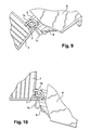
- the hooks are combined with jaws acting clamps able to grip the section of each foot.
- the transfer of the rack is effected by pivoting and reversing after tightening the clamps.
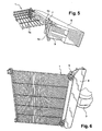
- each rack (1) is constituted by a grid (1a) made of filiform elements constituting a support plate as such, of generally rectangular shape.
- Two opposite sides of the rack has, at each of their free end, rings (1b) from which are formed feet (1c) also filiform elements of reduced height.
- the trays are stacked in a manner entangled and staggered, so that the feet (1c) of the different trays stacked are not aligned.
- Drawings are shown in the figures which show an example of entanglement of stacked racks.
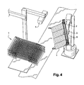
- the device for unstacking the trays thus entangled comprises, in combination, a manipulator robot (2) secured to an optical vision system. More particularly, the vision system is shaped to detect, on the one hand, the rack disposed at the top of the stack and, on the other hand, a gripping area of said rack to control the robot (2) with the manipulator head (3) is equipped with means (4) capable of hooking and lifting said rack from said gripping area.
- the gripping zone is constituted by the rings (1b) from which the feet (1c) are formed.
- the vision system includes a camera (5) suitably positioned to scan the top of the stack to search for the top rack.
- Another camera (6) is suitably positioned to scan the face of the stack of trays with the rings (1b) for gripping the search shelf immediately below the upper rack.
- the two cameras (5) and (6) are arranged in two orthogonal planes.
- the lighting is designed to allow extraction of the contours of the racks according to the requirements of the application.
- the image processing can detect the position of the racks in height and length.
- the manipulator robot (2) grips the upper rack.
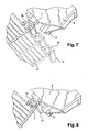
- the means that the manipulator head of the robot for lifting the upper rack are constituted by hooks (7) disposed on a support bar (8) at a spacing corresponding to the spacing between the rings (1b). These hooks (7) cooperate with the rings (1b) to allow lifting the upper rack and, consequently, to release it from one of its ends of the immediately lower rack ( Figures 2, 3 , 5 and 6 ).
- the support bar (8) equipped with the hooks (7) is mounted at the end of the head of the manipulator robot arm (2), in order to subject said bar to the various movements to which the head of the robot is conventionally attached.
- the support bar is mounted at the end of the arm with pivoting capacity, as will be indicated in the following description.
- the manipulator arm can transfer the captured rack in a substantially horizontal plane in order to disengage it from the stack in question and to position it anywhere.
- the hooks (7) are arranged on the support bar in combination with clamps (9).
- clamps (9) of any known and appropriate type, are actuated after lifting and disengagement of the upper rack, so as to grip the section of the feet (1b) ( figures 5 and 9 ).
- the system of vision comprises another camera (11) disposed in the area where must be positioned and unloaded the rack previously entered.
Landscapes
- Engineering & Computer Science (AREA)
- Mechanical Engineering (AREA)
- De-Stacking Of Articles (AREA)
- Manipulator (AREA)
- Load-Engaging Elements For Cranes (AREA)
- Particle Accelerators (AREA)
- Radiation-Therapy Devices (AREA)
- Absorbent Articles And Supports Therefor (AREA)
- Prostheses (AREA)
Claims (8)
- Vorrichtung zum Abstapeln von versetzt angeordneten ineinander verschachtelten Horden, dadurch gekennzeichnet, dass sie einen Greifroboter (2) umfasst, der mit einer Kamera (5) zusammenarbeitet, die so positioniert ist, um die Oberseite des Hordenstapels abzutasten und die obere Horde zu suchen, und mit einer anderen Kamera (6), die so positioniert ist, um die Vorderseite des Hordenstapels mit einer Greifzone (1b) abzutasten und die Horde zu suchen, die sich unmittelbar unter der oberen Horde befindet, um den besagten Roboter (2) zu steuern, dessen Greifkopf mit Einrichtungen (7) ausgestattet ist, die geeignet sind, sich ausgehend von der besagten Zone in die obere Horde einzuhaken und sie hochzuheben.
- Vorrichtung nach Anspruch 1, dadurch gekennzeichnet, dass das Sichtsystem eine weitere Kamera (11) umfasst, die in einem Bereich angeordnet ist, in dem die zuvor ergriffene Horde positioniert und abgelegt werden soll.
- Vorrichtung nach Anspruch 1, dadurch gekennzeichnet, dass die Greifzone jeder Horde aus zwei vorstehenden Ringen (1b) besteht, von denen aus Fußteile (1c) ausgebildet sind, wobei sich die besagten Ringe (1b) an jedem Ende mindestens einer Hordenseite (1) befinden.
- Vorrichtung nach einem der Ansprüche 1 - 3, dadurch gekennzeichnet, dass die Einrichtungen zur Anhebung der Horde aus Haken (7) bestehen, die in einem dem Abstand der Fußteile (1c) der Horden entsprechenden Achsabstand auf einer Halteleiste (8) angeordnet sind, wobei die Haken (7) mit den Ringen (1b) zusammenwirken, die an jedem Fußteil vorstehen, während die Leiste (8) am Armende des Greifroboters angebracht ist.
- Vorrichtung nach Anspruch 4, dadurch gekennzeichnet, dass die Halteleiste (8) schwenkbar am Ende des Armes angebracht ist.
- Vorrichtung 4, dadurch gekennzeichnet, dass die Haken (7) mit Backen (9) kombiniert sind, die als Zangen dienen und geeignet sind, den Querschnitt jedes Fußteils zu umschließen.
- Vorrichtung nach einem der vorhergehenden Ansprüche 1 - 6, dadurch gekennzeichnet, dass der Roboter (2) von einer Steuer- und Programmiereinheit abhängt, die den Greiferkopf den nachstehenden Bewegungsablauf beschreiben lässt:- Einhaken der oberen Horde;- Anheben der Horde;- Verlagerung der Horde zu einer vorbestimmten Station;- Ablage der Horde an der Station.
- Vorrichtung nach Anspruch 7, dadurch gekennzeichnet, dass die Verlagerung der Horde nach dem Zupacken der Zangen durch eine Schwenk- und Umkehrbewegung erfolgt.
Applications Claiming Priority (1)
| Application Number | Priority Date | Filing Date | Title |
|---|---|---|---|
| FR0757872A FR2921351B1 (fr) | 2007-09-26 | 2007-09-26 | Dispositif pour desempiler des claies enchevetrees en quinconce |
Publications (2)
| Publication Number | Publication Date |
|---|---|
| EP2042452A1 EP2042452A1 (de) | 2009-04-01 |
| EP2042452B1 true EP2042452B1 (de) | 2010-12-01 |
Family
ID=39362534
Family Applications (1)
| Application Number | Title | Priority Date | Filing Date |
|---|---|---|---|
| EP08300272A Active EP2042452B1 (de) | 2007-09-26 | 2008-09-25 | Vorrichtung zum Abtragen von ineinander verkeilten, versetzt angeordneten Gitterroste |
Country Status (4)
| Country | Link |
|---|---|
| EP (1) | EP2042452B1 (de) |
| AT (1) | ATE490210T1 (de) |
| DE (1) | DE602008003729D1 (de) |
| FR (1) | FR2921351B1 (de) |
Cited By (1)
| Publication number | Priority date | Publication date | Assignee | Title |
|---|---|---|---|---|
| CN111547435A (zh) * | 2020-05-25 | 2020-08-18 | 福州经济技术开发区佳俞乐科技有限公司 | 一种可以实现高处货架货物存取的小车 |
Families Citing this family (8)
| Publication number | Priority date | Publication date | Assignee | Title |
|---|---|---|---|---|
| CN104670912B (zh) * | 2015-02-03 | 2019-04-30 | 徐州德坤电气科技有限公司 | 一种基于数字总线的小u形管抓取排序码放系统 |
| CN104670911B (zh) * | 2015-02-03 | 2019-04-30 | 徐州德坤电气科技有限公司 | 一种基于数字总线的小u形管抓取排序码放单元 |
| CN104670775B (zh) * | 2015-02-03 | 2019-05-31 | 徐州德坤电气科技有限公司 | 一种基于数字总线的循环供应物料的托架及托盘 |
| CN106628928B (zh) * | 2017-01-22 | 2020-02-28 | 深圳訾岽科技有限公司 | 一种组合式测试流水线 |
| CN110171658A (zh) * | 2019-07-04 | 2019-08-27 | 安吉八塔机器人有限公司 | 一种堆垛系统 |
| CN113585781B (zh) * | 2020-04-30 | 2022-08-12 | 广东博智林机器人有限公司 | 供砖机器人 |
| CN111762582A (zh) * | 2020-06-03 | 2020-10-13 | 广东硕泰智能装备有限公司 | 自动拆垛系统 |
| CN115159143B (zh) * | 2022-08-23 | 2024-05-07 | 山东三江智能装备有限公司 | 一种单柱式平推码垛机 |
Family Cites Families (4)
| Publication number | Priority date | Publication date | Assignee | Title |
|---|---|---|---|---|
| FR2576005B1 (fr) * | 1985-01-15 | 1990-07-20 | Realisa Indles Et | Procede et dispositif automatique de depalettisation |
| DE102005015388A1 (de) * | 2005-04-04 | 2006-10-05 | Alpma Alpenland Maschinenbau Gmbh | Vorrichtung zum Stapeln von Lebensmittelhorden |
| DE102005020977A1 (de) * | 2005-04-29 | 2006-11-02 | Holzma Plattenaufteiltechnik Gmbh | Abstapelungsvorrichtung zum Abstapeln plattenförmiger Werkstücke |
| DE202005017559U1 (de) * | 2005-11-10 | 2006-01-05 | Hermann Waldner Gmbh & Co. Kg | Ausrichtvorrichtung |
-
2007
- 2007-09-26 FR FR0757872A patent/FR2921351B1/fr not_active Expired - Fee Related
-
2008
- 2008-09-25 EP EP08300272A patent/EP2042452B1/de active Active
- 2008-09-25 AT AT08300272T patent/ATE490210T1/de not_active IP Right Cessation
- 2008-09-25 DE DE602008003729T patent/DE602008003729D1/de active Active
Cited By (2)
| Publication number | Priority date | Publication date | Assignee | Title |
|---|---|---|---|---|
| CN111547435A (zh) * | 2020-05-25 | 2020-08-18 | 福州经济技术开发区佳俞乐科技有限公司 | 一种可以实现高处货架货物存取的小车 |
| CN111547435B (zh) * | 2020-05-25 | 2020-12-01 | 江苏天佑液压科技有限公司 | 一种可以实现高处货架货物存取的小车 |
Also Published As
| Publication number | Publication date |
|---|---|
| FR2921351A1 (fr) | 2009-03-27 |
| FR2921351B1 (fr) | 2010-03-05 |
| EP2042452A1 (de) | 2009-04-01 |
| DE602008003729D1 (de) | 2011-01-13 |
| ATE490210T1 (de) | 2010-12-15 |
Similar Documents
| Publication | Publication Date | Title |
|---|---|---|
| EP2042452B1 (de) | Vorrichtung zum Abtragen von ineinander verkeilten, versetzt angeordneten Gitterroste | |
| EP1701602B1 (de) | Anordnung und Verfahren zum Verpacken eines Gestells für Computer, Gestell für Computer und Palette für dieses Gestell | |
| TWI378065B (de) | ||
| EP2551222B1 (de) | Verfahren zur Beförderung von Produkten, insbesondere von Lebensmitteltranchen | |
| EP3227189B1 (de) | Vorrichtung und verfahren zum stapeln von verpackungen unterschiedlicher grössen | |
| EP3214025A1 (de) | Palettengreifer | |
| WO2019243674A1 (fr) | Appareil et procédé de transfert, vers une ligne de traitement, d'imprimés initialement conditionnés en liasse | |
| WO2017177393A1 (en) | Gripper, de-palletizing system, searching method, gripping method and de-palletizing method | |
| US9701489B2 (en) | Depalletiser for trays of eggs | |
| WO2016128662A1 (fr) | Procede et systeme de dechargement de colis | |
| FR3060547A1 (fr) | Appareil et procede de transfert, vers une ligne de traitement, d'imprimes initialement conditionnes en liasse | |
| FR3060538A1 (fr) | Procede et appareil pour sectionner un lien entourant une liasse d'imprimes provenant d'une palette | |
| FR3125452A1 (fr) | Outil de préhension de caisse et système de palettisation et/ou de dépalettisation le comprenant | |
| EP0651941A1 (de) | Verfahren und Vorrichtung zum Anbringen und/oder Zurückholen von Käse auf/von Horden, und deren Verwendung in Wenden von Käse | |
| FR2640946A1 (en) | Machine for automatic conveying and destacking of workpieces having a complex shape | |
| CH619672A5 (de) | ||
| FR3113659A1 (fr) | Système de stockage de bacs comprenant des robots équipés de crochets ou de doigts de préhension et de levage de bacs et procédé de préhension de bacs correspondant | |
| WO2019097155A1 (fr) | Dispositif de palettisation robotisee muni d'un magasin d'intercalaires | |
| FR3162429A1 (fr) | Prehenseur a onglet ecarteur, dispositif de depalettisation dote d’un tel prehenseur, et procede de depalettisation associe | |
| FR3059308B1 (fr) | Rehausse pour le stockage d'objets a manutentionner | |
| FR2816930A1 (fr) | Procede et dispositif pour le depilage, la separation et la distribution automatiques de pieces d'oeuvre | |
| FR3116223A1 (fr) | Dispositif et procédé de transfert de blocs élastomériques | |
| FR3149317A1 (fr) | Dispositif de levage suspendu d’éléments allongés permettant differentes inclinaisons | |
| FR3156055A1 (fr) | Outil préhenseur pour contenant grillagé et système de transfert le comprenant | |
| FR2804944A1 (fr) | Appareil pour l'empilage de plaques |
Legal Events
| Date | Code | Title | Description |
|---|---|---|---|
| PUAI | Public reference made under article 153(3) epc to a published international application that has entered the european phase |
Free format text: ORIGINAL CODE: 0009012 |
|
| AK | Designated contracting states |
Kind code of ref document: A1 Designated state(s): AT BE BG CH CY CZ DE DK EE ES FI FR GB GR HR HU IE IS IT LI LT LU LV MC MT NL NO PL PT RO SE SI SK TR |
|
| AX | Request for extension of the european patent |
Extension state: AL BA MK RS |
|
| 17P | Request for examination filed |
Effective date: 20090505 |
|
| AKX | Designation fees paid |
Designated state(s): AT BE BG CH CY CZ DE DK EE ES FI FR GB GR HR HU IE IS IT LI LT LU LV MC MT NL NO PL PT RO SE SI SK TR |
|
| GRAP | Despatch of communication of intention to grant a patent |
Free format text: ORIGINAL CODE: EPIDOSNIGR1 |
|
| GRAC | Information related to communication of intention to grant a patent modified |
Free format text: ORIGINAL CODE: EPIDOSCIGR1 |
|
| GRAC | Information related to communication of intention to grant a patent modified |
Free format text: ORIGINAL CODE: EPIDOSCIGR1 |
|
| GRAS | Grant fee paid |
Free format text: ORIGINAL CODE: EPIDOSNIGR3 |
|
| GRAA | (expected) grant |
Free format text: ORIGINAL CODE: 0009210 |
|
| AK | Designated contracting states |
Kind code of ref document: B1 Designated state(s): AT BE BG CH CY CZ DE DK EE ES FI FR GB GR HR HU IE IS IT LI LT LU LV MC MT NL NO PL PT RO SE SI SK TR |
|
| REG | Reference to a national code |
Ref country code: GB Ref legal event code: FG4D Free format text: NOT ENGLISH |
|
| REG | Reference to a national code |
Ref country code: CH Ref legal event code: EP |
|
| REG | Reference to a national code |
Ref country code: IE Ref legal event code: FG4D |
|
| REF | Corresponds to: |
Ref document number: 602008003729 Country of ref document: DE Date of ref document: 20110113 Kind code of ref document: P |
|
| REG | Reference to a national code |
Ref country code: NL Ref legal event code: VDEP Effective date: 20101201 |
|
| PG25 | Lapsed in a contracting state [announced via postgrant information from national office to epo] |
Ref country code: NO Free format text: LAPSE BECAUSE OF FAILURE TO SUBMIT A TRANSLATION OF THE DESCRIPTION OR TO PAY THE FEE WITHIN THE PRESCRIBED TIME-LIMIT Effective date: 20110301 Ref country code: LT Free format text: LAPSE BECAUSE OF FAILURE TO SUBMIT A TRANSLATION OF THE DESCRIPTION OR TO PAY THE FEE WITHIN THE PRESCRIBED TIME-LIMIT Effective date: 20101201 |
|
| LTIE | Lt: invalidation of european patent or patent extension |
Effective date: 20101201 |
|
| PG25 | Lapsed in a contracting state [announced via postgrant information from national office to epo] |
Ref country code: FI Free format text: LAPSE BECAUSE OF FAILURE TO SUBMIT A TRANSLATION OF THE DESCRIPTION OR TO PAY THE FEE WITHIN THE PRESCRIBED TIME-LIMIT Effective date: 20101201 Ref country code: CY Free format text: LAPSE BECAUSE OF FAILURE TO SUBMIT A TRANSLATION OF THE DESCRIPTION OR TO PAY THE FEE WITHIN THE PRESCRIBED TIME-LIMIT Effective date: 20101201 Ref country code: AT Free format text: LAPSE BECAUSE OF FAILURE TO SUBMIT A TRANSLATION OF THE DESCRIPTION OR TO PAY THE FEE WITHIN THE PRESCRIBED TIME-LIMIT Effective date: 20101201 Ref country code: BG Free format text: LAPSE BECAUSE OF FAILURE TO SUBMIT A TRANSLATION OF THE DESCRIPTION OR TO PAY THE FEE WITHIN THE PRESCRIBED TIME-LIMIT Effective date: 20110301 Ref country code: SE Free format text: LAPSE BECAUSE OF FAILURE TO SUBMIT A TRANSLATION OF THE DESCRIPTION OR TO PAY THE FEE WITHIN THE PRESCRIBED TIME-LIMIT Effective date: 20101201 Ref country code: LV Free format text: LAPSE BECAUSE OF FAILURE TO SUBMIT A TRANSLATION OF THE DESCRIPTION OR TO PAY THE FEE WITHIN THE PRESCRIBED TIME-LIMIT Effective date: 20101201 Ref country code: NL Free format text: LAPSE BECAUSE OF FAILURE TO SUBMIT A TRANSLATION OF THE DESCRIPTION OR TO PAY THE FEE WITHIN THE PRESCRIBED TIME-LIMIT Effective date: 20101201 Ref country code: SI Free format text: LAPSE BECAUSE OF FAILURE TO SUBMIT A TRANSLATION OF THE DESCRIPTION OR TO PAY THE FEE WITHIN THE PRESCRIBED TIME-LIMIT Effective date: 20101201 Ref country code: HR Free format text: LAPSE BECAUSE OF FAILURE TO SUBMIT A TRANSLATION OF THE DESCRIPTION OR TO PAY THE FEE WITHIN THE PRESCRIBED TIME-LIMIT Effective date: 20101201 |
|
| REG | Reference to a national code |
Ref country code: IE Ref legal event code: FD4D |
|
| PG25 | Lapsed in a contracting state [announced via postgrant information from national office to epo] |
Ref country code: GR Free format text: LAPSE BECAUSE OF FAILURE TO SUBMIT A TRANSLATION OF THE DESCRIPTION OR TO PAY THE FEE WITHIN THE PRESCRIBED TIME-LIMIT Effective date: 20110302 |
|
| PG25 | Lapsed in a contracting state [announced via postgrant information from national office to epo] |
Ref country code: IE Free format text: LAPSE BECAUSE OF FAILURE TO SUBMIT A TRANSLATION OF THE DESCRIPTION OR TO PAY THE FEE WITHIN THE PRESCRIBED TIME-LIMIT Effective date: 20101201 Ref country code: PT Free format text: LAPSE BECAUSE OF FAILURE TO SUBMIT A TRANSLATION OF THE DESCRIPTION OR TO PAY THE FEE WITHIN THE PRESCRIBED TIME-LIMIT Effective date: 20110401 Ref country code: CZ Free format text: LAPSE BECAUSE OF FAILURE TO SUBMIT A TRANSLATION OF THE DESCRIPTION OR TO PAY THE FEE WITHIN THE PRESCRIBED TIME-LIMIT Effective date: 20101201 Ref country code: ES Free format text: LAPSE BECAUSE OF FAILURE TO SUBMIT A TRANSLATION OF THE DESCRIPTION OR TO PAY THE FEE WITHIN THE PRESCRIBED TIME-LIMIT Effective date: 20110312 Ref country code: EE Free format text: LAPSE BECAUSE OF FAILURE TO SUBMIT A TRANSLATION OF THE DESCRIPTION OR TO PAY THE FEE WITHIN THE PRESCRIBED TIME-LIMIT Effective date: 20101201 Ref country code: IS Free format text: LAPSE BECAUSE OF FAILURE TO SUBMIT A TRANSLATION OF THE DESCRIPTION OR TO PAY THE FEE WITHIN THE PRESCRIBED TIME-LIMIT Effective date: 20110401 |
|
| PG25 | Lapsed in a contracting state [announced via postgrant information from national office to epo] |
Ref country code: PL Free format text: LAPSE BECAUSE OF FAILURE TO SUBMIT A TRANSLATION OF THE DESCRIPTION OR TO PAY THE FEE WITHIN THE PRESCRIBED TIME-LIMIT Effective date: 20101201 Ref country code: SK Free format text: LAPSE BECAUSE OF FAILURE TO SUBMIT A TRANSLATION OF THE DESCRIPTION OR TO PAY THE FEE WITHIN THE PRESCRIBED TIME-LIMIT Effective date: 20101201 Ref country code: RO Free format text: LAPSE BECAUSE OF FAILURE TO SUBMIT A TRANSLATION OF THE DESCRIPTION OR TO PAY THE FEE WITHIN THE PRESCRIBED TIME-LIMIT Effective date: 20101201 |
|
| PLBE | No opposition filed within time limit |
Free format text: ORIGINAL CODE: 0009261 |
|
| STAA | Information on the status of an ep patent application or granted ep patent |
Free format text: STATUS: NO OPPOSITION FILED WITHIN TIME LIMIT |
|
| PG25 | Lapsed in a contracting state [announced via postgrant information from national office to epo] |
Ref country code: DK Free format text: LAPSE BECAUSE OF FAILURE TO SUBMIT A TRANSLATION OF THE DESCRIPTION OR TO PAY THE FEE WITHIN THE PRESCRIBED TIME-LIMIT Effective date: 20101201 |
|
| 26N | No opposition filed |
Effective date: 20110902 |
|
| REG | Reference to a national code |
Ref country code: DE Ref legal event code: R097 Ref document number: 602008003729 Country of ref document: DE Effective date: 20110902 |
|
| PG25 | Lapsed in a contracting state [announced via postgrant information from national office to epo] |
Ref country code: IT Free format text: LAPSE BECAUSE OF FAILURE TO SUBMIT A TRANSLATION OF THE DESCRIPTION OR TO PAY THE FEE WITHIN THE PRESCRIBED TIME-LIMIT Effective date: 20101201 |
|
| PG25 | Lapsed in a contracting state [announced via postgrant information from national office to epo] |
Ref country code: MC Free format text: LAPSE BECAUSE OF NON-PAYMENT OF DUE FEES Effective date: 20110930 |
|
| REG | Reference to a national code |
Ref country code: FR Ref legal event code: CD Owner name: SILEANE, FR Effective date: 20120924 |
|
| PG25 | Lapsed in a contracting state [announced via postgrant information from national office to epo] |
Ref country code: MT Free format text: LAPSE BECAUSE OF FAILURE TO SUBMIT A TRANSLATION OF THE DESCRIPTION OR TO PAY THE FEE WITHIN THE PRESCRIBED TIME-LIMIT Effective date: 20101201 |
|
| GBPC | Gb: european patent ceased through non-payment of renewal fee |
Effective date: 20120925 |
|
| PG25 | Lapsed in a contracting state [announced via postgrant information from national office to epo] |
Ref country code: LU Free format text: LAPSE BECAUSE OF NON-PAYMENT OF DUE FEES Effective date: 20110925 |
|
| PG25 | Lapsed in a contracting state [announced via postgrant information from national office to epo] |
Ref country code: GB Free format text: LAPSE BECAUSE OF NON-PAYMENT OF DUE FEES Effective date: 20120925 |
|
| PG25 | Lapsed in a contracting state [announced via postgrant information from national office to epo] |
Ref country code: TR Free format text: LAPSE BECAUSE OF FAILURE TO SUBMIT A TRANSLATION OF THE DESCRIPTION OR TO PAY THE FEE WITHIN THE PRESCRIBED TIME-LIMIT Effective date: 20101201 |
|
| PG25 | Lapsed in a contracting state [announced via postgrant information from national office to epo] |
Ref country code: HU Free format text: LAPSE BECAUSE OF FAILURE TO SUBMIT A TRANSLATION OF THE DESCRIPTION OR TO PAY THE FEE WITHIN THE PRESCRIBED TIME-LIMIT Effective date: 20101201 |
|
| REG | Reference to a national code |
Ref country code: FR Ref legal event code: PLFP Year of fee payment: 8 |
|
| REG | Reference to a national code |
Ref country code: FR Ref legal event code: PLFP Year of fee payment: 9 |
|
| REG | Reference to a national code |
Ref country code: FR Ref legal event code: PLFP Year of fee payment: 10 |
|
| REG | Reference to a national code |
Ref country code: FR Ref legal event code: PLFP Year of fee payment: 11 |
|
| P01 | Opt-out of the competence of the unified patent court (upc) registered |
Effective date: 20230527 |
|
| PGFP | Annual fee paid to national office [announced via postgrant information from national office to epo] |
Ref country code: DE Payment date: 20240912 Year of fee payment: 17 |
|
| PGFP | Annual fee paid to national office [announced via postgrant information from national office to epo] |
Ref country code: BE Payment date: 20240916 Year of fee payment: 17 |
|
| PGFP | Annual fee paid to national office [announced via postgrant information from national office to epo] |
Ref country code: FR Payment date: 20240926 Year of fee payment: 17 |
|
| PGFP | Annual fee paid to national office [announced via postgrant information from national office to epo] |
Ref country code: CH Payment date: 20241004 Year of fee payment: 17 |