EP2040883B1 - Elektrohandwerkzeugmaschine - Google Patents
Elektrohandwerkzeugmaschine Download PDFInfo
- Publication number
- EP2040883B1 EP2040883B1 EP07728811.6A EP07728811A EP2040883B1 EP 2040883 B1 EP2040883 B1 EP 2040883B1 EP 07728811 A EP07728811 A EP 07728811A EP 2040883 B1 EP2040883 B1 EP 2040883B1
- Authority
- EP
- European Patent Office
- Prior art keywords
- spindle
- vibration damping
- damping element
- tool
- electric power
- Prior art date
- Legal status (The legal status is an assumption and is not a legal conclusion. Google has not performed a legal analysis and makes no representation as to the accuracy of the status listed.)
- Ceased
Links
- 238000013016 damping Methods 0.000 claims description 87
- 230000008878 coupling Effects 0.000 claims description 15
- 238000010168 coupling process Methods 0.000 claims description 15
- 238000005859 coupling reaction Methods 0.000 claims description 15
- 239000000463 material Substances 0.000 claims description 7
- 229920001971 elastomer Polymers 0.000 claims description 5
- 239000000806 elastomer Substances 0.000 claims description 5
- 239000004744 fabric Substances 0.000 claims description 5
- 239000002184 metal Substances 0.000 claims description 5
- 239000004033 plastic Substances 0.000 claims description 3
- 229920003023 plastic Polymers 0.000 claims description 3
- 230000005540 biological transmission Effects 0.000 description 9
- 238000002955 isolation Methods 0.000 description 4
- 239000011248 coating agent Substances 0.000 description 2
- 238000000576 coating method Methods 0.000 description 2
- 239000007788 liquid Substances 0.000 description 2
- 238000005498 polishing Methods 0.000 description 2
- 238000004073 vulcanization Methods 0.000 description 2
- CWYNVVGOOAEACU-UHFFFAOYSA-N Fe2+ Chemical compound [Fe+2] CWYNVVGOOAEACU-UHFFFAOYSA-N 0.000 description 1
- 229910000831 Steel Inorganic materials 0.000 description 1
- 230000006835 compression Effects 0.000 description 1
- 238000007906 compression Methods 0.000 description 1
- 239000013536 elastomeric material Substances 0.000 description 1
- 238000003754 machining Methods 0.000 description 1
- 230000003534 oscillatory effect Effects 0.000 description 1
- 239000007787 solid Substances 0.000 description 1
- 238000005507 spraying Methods 0.000 description 1
- 239000010959 steel Substances 0.000 description 1
- 229920001169 thermoplastic Polymers 0.000 description 1
- 229920001187 thermosetting polymer Polymers 0.000 description 1
- 239000004416 thermosoftening plastic Substances 0.000 description 1
Images



Classifications
-
- B—PERFORMING OPERATIONS; TRANSPORTING
- B25—HAND TOOLS; PORTABLE POWER-DRIVEN TOOLS; MANIPULATORS
- B25F—COMBINATION OR MULTI-PURPOSE TOOLS NOT OTHERWISE PROVIDED FOR; DETAILS OR COMPONENTS OF PORTABLE POWER-DRIVEN TOOLS NOT PARTICULARLY RELATED TO THE OPERATIONS PERFORMED AND NOT OTHERWISE PROVIDED FOR
- B25F5/00—Details or components of portable power-driven tools not particularly related to the operations performed and not otherwise provided for
- B25F5/006—Vibration damping means
-
- B—PERFORMING OPERATIONS; TRANSPORTING
- B24—GRINDING; POLISHING
- B24B—MACHINES, DEVICES, OR PROCESSES FOR GRINDING OR POLISHING; DRESSING OR CONDITIONING OF ABRADING SURFACES; FEEDING OF GRINDING, POLISHING, OR LAPPING AGENTS
- B24B23/00—Portable grinding machines, e.g. hand-guided; Accessories therefor
- B24B23/02—Portable grinding machines, e.g. hand-guided; Accessories therefor with rotating grinding tools; Accessories therefor
- B24B23/028—Angle tools
-
- B—PERFORMING OPERATIONS; TRANSPORTING
- B24—GRINDING; POLISHING
- B24B—MACHINES, DEVICES, OR PROCESSES FOR GRINDING OR POLISHING; DRESSING OR CONDITIONING OF ABRADING SURFACES; FEEDING OF GRINDING, POLISHING, OR LAPPING AGENTS
- B24B41/00—Component parts such as frames, beds, carriages, headstocks
- B24B41/007—Weight compensation; Temperature compensation; Vibration damping
-
- B—PERFORMING OPERATIONS; TRANSPORTING
- B24—GRINDING; POLISHING
- B24B—MACHINES, DEVICES, OR PROCESSES FOR GRINDING OR POLISHING; DRESSING OR CONDITIONING OF ABRADING SURFACES; FEEDING OF GRINDING, POLISHING, OR LAPPING AGENTS
- B24B45/00—Means for securing grinding wheels on rotary arbors
Definitions
- the invention relates to an electric power tool with at least one driven, mounted in at least one bearing rotary member.
- An electric hand tool according to the preamble of claim 1 is in WO2006 / 058898A disclosed.
- Such an electric hand tool machine is known. It is an electric hand tool, whose associated tool is driven in rotation.
- the electric hand tool machine is, for example, a grinding or polishing tool whose tool is designed as a grinding or polishing wheel.
- the rotating part is a rotating element of the electric hand tool machine, which is arranged in a drive train between the tool and the bearing or the tool - or a tool element of the tool - itself.
- the term "rotary member" in the context of this invention does not mean that the rotary member must be a manufactured on a lathe element.
- When working with such an electric hand tool with a rotating part occur more or less intense vibrations. These vibrations are mainly due to an imbalance of the rotating at high speed tool, as well as the machining of a workpiece with the tool.
- the vibrations are transmitted to the housing via the bearing and also to the operator of the handheld power tool via the handles. These vibrations put a strain on the operator and may cause harm to the operator when working with the handheld power tool for extended periods of time.
- the WO 2006/058898 A2 relates to a rotating tool which can be mounted on a drive spindle by means of a tensioning device.
- the clamping device comprises a clamping flange and a clamping nut, which are each provided with a coating which is in contact with the tool in order to avoid vibrations.
- D1 thus discloses a trained as a tool rotary part, which has a vibration damping element (Coating) is mounted vibration-decoupled, wherein the bearing is formed by the clamping device.
- the electric hand tool according to the invention has a rotary part which is vibration-decoupled from the bearing.
- the rotary part of the electric power tool is a rotating element which is arranged between a tool of the electric power tool and the bearing or the tool itself. It serves to transmit torque from the drive to a processing area of a tool associated with the electric hand tool.
- rotary part and bearings associated with each other, but do not interact directly.
- the rotary part mounted in a bearing can, for example, also be mounted in the bearing via intermediate elements. Due to the vibration isolation of the rotating part and the bearing, the vibrations absorbed by the tool are transmitted to the bearing - and thus also to the housing - in a highly damped way. Due to the vibration isolation, these vibrations are not transmitted to the operator.
- the rotary part is a spindle.
- the spindle is a drive spindle for rotating the tool.
- the rotary part is a tool associated with the electric hand tool. If the rotating part is the tool itself, then this tool is connected to the drive of the electric hand-held power tool via at least one drive element.
- the vibration decoupling can be done for example via this drive element.
- the rotary part is a tool element. If the tool has an element for vibration decoupling, then the tool element is that part of the tool that is part of the tool is decoupled with the bearing connected parts. This tool element is then the rotating part.
- the rotary member is vibration-decoupled from the bearing by at least one vibration-damping element.
- the rotary part is, for example, a spindle serving to drive the tool, then it can be connected to the bearing via the vibration damping element.
- the spindle is circumferentially surrounded, for example, in an axial region by a vibration damping element which rests in the bearing.
- At least one intermediate element arranged between the bearing and the rotary part is provided.
- the intermediate element is in particular a drive element of the rotary part serving intermediate element. It is not necessarily vibration-decoupled from the bearing.
- the intermediate element is a transmission element, in particular a ring gear, a transmission.
- the transmission can, for example, specify a gear ratio or - designed as an angle gear - connect a motor with a work spindle, the axis of the spindle and the motor axis are perpendicular to each other.
- a bevel gear with a crown gear act together in such an angle gear.
- the intermediate element is a spindle.
- the spindle formed as an intermediate element of the torque transmission from the drive to the rotary member, wherein the rotary member is for example a tool.
- the intermediate element itself is not necessarily vibration-decoupled from the bearing in contrast to the rotating part.
- the vibration damping element between the bearing and the rotary member and / or between the intermediate member and the rotary member and / or between the bearing and the intermediate member is arranged. Since the vibration damping element decouples the vibrations of the rotating part relative to the bearing, these possibilities for the arrangement of the vibration damping element arise.
- the vibration damping element can be arranged directly between the bearing and the rotary part. If, in addition, an intermediate element is provided, then the vibration damping element can be arranged in a serial arrangement of bearing, intermediate element and rotary part between the intermediate element and the rotary part or between the bearing and the intermediate element. If a plurality of bearings and / or a plurality of vibration damping elements are provided, combinations of these arrangements may also be provided.
- the vibration damping element is arranged.
- the rotary member is vibration-decoupled from the bearing by a vibration-damping member which is not connected to either the rotary member or the bearing.
- the vibration damping element is a damping spring device and / or a knitted fabric and / or an inherently elastic vibration damping element and / or a fluidic vibration damping element.
- the damping spring device has at least one spring element and a damping device.
- the spring element may be, for example, a leaf spring, a coil spring, a plate spring or another spring.
- the spring element may have the vibration damping device integrally.
- the knit consists of interlocking elements, which against each other not a rigid arrangement, but against each other have certain game. This game is dictated by the density of the knit.
- the intrinsic elastic vibration damping element consists of an elastically deformable material
- the fluidic vibration damping element consists for example of a damper pad with an elastic sheath and a filling of a gel and / or a liquid and / or a gas.
- the material of the damping spring device and / or the knitted fabric is metal and / or plastic.
- the metal is in particular a ferrous metal such as steel.
- the plastics are, for example, thermoplastics, thermosets, elastomers, although material combinations of different materials are possible.
- the intrinsic elastic vibration damping element is an elastomer element.
- Elastomeric material has good intrinsic elastic properties, can be formed well and connected by vulcanization or vulcanization with other materials.
- the vibration damping element is arranged as a coupling device between the ring gear and the spindle and transmits a torque. If the spindle is driven by a gear with a ring gear, this is mounted in a bearing associated with the crown gear. Alternatively, the ring gear can be stored in several camps. Between the ring gear and the spindle designed as a coupling device vibration damping element is arranged and takes on two functions: It is used for vibration isolation of the spindle relative to the bearing, wherein the spindle is the rotary member or the rotary member with the spindle against the bearing is vibration decoupled.
- the vibration damping element serves as a coupling device and ensures a torque transmission from the ring gear of the transmission on the spindle.
- the vibration damping element frictionally connects the ring gear with the spindle.
- a positive connection of the ring gear and the spindle on the vibration damping element limits the freedom of movement between the ring gear and the spindle.
- the coupling means engaging in recesses of the ring gear, the spindle encompassing Wellfederhülse, a spindle engaging around the sleeve with at least one engaging in a recess of the ring gear spring tab or a spring device with at least one spring-loaded ball.
- These three alternative embodiments of the coupling device each ensure a positive and a force fit between the spindle and the ring gear, wherein the coupling device simultaneously serves the vibration decoupling.
- the vibration damping element is attached to the tool.
- the vibration damping element may be attached directly to the tool.
- the vibration damping element for example, be attached to a tool shank of the tool.
- the vibration damping element may alternatively be integrated into the tool.
- the rotary part is in particular the tool element.
- the vibration damping element is attached to the spindle or the ring gear.
- the vibration damping element can be arranged, for example, between the spindle and a ring gear surrounding an axial region of the spindle.
- the vibration damping element is a coupling device formed surrounds the spindle in the axial region and provides between the vibration damping element and the ring gear at the same time for positive and positive connection, and for a vibration decoupling of crown and spindle.
- vibration damping element to a fastening device - for releasably securing the tool and the spindle - is attached.
- a fastening device may for example consist of a clamping flange and a clamping nut, in each of which a vibration damping element is attached by spraying.
- the FIG. 1 shows a part of a non-inventive, designed as angle grinder electric hand tool.
- a transmission housing 1 there is a rotary part 3 designed as a spindle 2 with a longitudinal axis 4.
- the spindle 2 is mounted at one end 5 in a bearing 7 designed as a spindle bearing 6.
- the spindle bearing 6 is formed as a sliding bearing 8.
- the spindle bearing 6 may also be formed as a needle bearing or ball bearings.
- the spindle 2 is surrounded radially by a gear element 11 designed as a ring gear 10.
- the ring gear 10 is pressed in the central portion 9 on the spindle 2 and fixedly connected thereto.
- a bearing 13 designed as a ball bearing 13 is pressed onto the spindle 2.
- the ball bearing 12 is fixedly connected to a bearing flange 14 which radially surrounds the ball bearing 12.
- the bearing flange 14 is in turn connected to the transmission housing 1.
- the rotary member 3 is not vibration decoupled from the bearing 7,13.
- FIG. 2 shows the connection of the formed as a spindle 2 rotary part 3 of FIG. 1 with a designed as a grinding wheel 15 tool 16.
- the connection between the spindle 2 and the tool 16 is made by a fastening device 17 at one end 5 of the opposite end 18 of the spindle 2.
- the fastening device 17 consists of a mounting flange 19 and a mounting flange 19 on the tool side opposite clamping nut 20 for clamping attachment of the grinding wheel.
- FIGS. 1 and 2 show in combination a not according to the invention storage of the rotary member 3. If the rotary member 3 is not formed by the spindle 2, but by the tool 16, the spindle 3 is the FIG. 1 only an intermediate element 21 which is arranged between the formed as a tool 16 rotary member 3 and the bearings 7,13. Since the tool 16 is not vibration-decoupled from the spindle 2, and the rotary member 3 formed as a tool 16 is the FIGS. 1 and 2 not vibration-decoupled from the bearing 7,13.
- FIGS. 3 to 10C show arrangements according to the invention for vibration decoupling of the rotary member 3 relative to the bearing 7, 13.
- Die FIG. 3 shows a vibration decoupling of the formed as a tool 16 rotary member 3 relative to a bearing, not shown, of the spindle 2
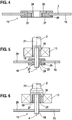
- FIG. 3 essentially the FIG. 2 so that only the differences should be discussed here.
- the fastening device 17 has two Vibration damping elements 22,23 for vibration decoupling of the formed as a tool 16 rotary member 3 relative to the formed as a spindle 2 intermediate element 21.
- the trained as a grinding wheel 15 tool 16 is clamped for mounting in a known manner, with the difference that there is at least one vibration damping element 22,23 between the mounting flange 19 and the clamping nut 20.
- This vibration damping element 22,23 may be inserted as a separate vibration damping element or fixedly mounted on the clamping nut 20 and / or the mounting flange 19.
- the solid vibration damping element 22, 23 may, for example, be sprayed onto the clamping nut 20 and / or the fastening flange 18.
- FIG. 4 shows an alternative arrangement for vibration isolation of the formed as a tool 16 rotating part 3 of an intermediate element, not shown, which is arranged between the rotary member 3 and the bearing 7,13.
- the vibration damping element 22 is attached to the formed as a grinding wheel 15 rotary member 3 and provides a connection to a formed as a clamping sleeve 24 centering sleeve 25.
- the centering sleeve 25 is for example in a consisting of a mounting flange 19 and a clamping nut 20 fastening device 17 for Attached to a spindle 2 clamped.
- the vibration damping element 22 is a self-elastic vibration damping element 27 designed as an elastomer element 26.
- This elastomer element 26 achieves damping or vibration decoupling between the rotary part 3 designed as a grinding wheel 15 and the intermediate element 21 designed as a spindle 2, which decouples the vibration of the rotary part 3 relative to the bearing, not shown, of the spindle 2 causes.
- the FIG. 5 shows an arrangement in which the vibration damping element 22 is integrated into the tool 16.
- the tool 16 consists of a tool shank 28, a tool element 29 designed as a grinding wheel 15 and the vibration damping element 22.
- the tool shank 28 of the tool 16 is arranged along the longitudinal axis 4 and received in the end 18 of the spindle 2.
- the spindle 2 is in this embodiment, as the tool shank 28, an intermediate element 21.
- the end 18 of the spindle 2 is radially surrounded by the bearing 13 designed as a ball bearing.
- FIG. 6 shows a consisting of a tool shank 28 and a tool element 29 tool 16, wherein the complete tool 16 forms the rotary member 3.
- the tool shank 28 is received in a recess 30 from the end 18 of the spindle 2 via an intrinsic elastic vibration damping element 27 in an axial recess of the spindle 2.
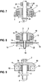
- FIG. 7 shows the bearing of the formed as a spindle 2 rotary member 3 in a ring gear 10 and a housing part 31.
- the end 5 of the spindle 2 is articulated via the vibration damping element 22 in the housing part 31.
- the central portion 9 of the spindle 2 is mounted on the vibration damping element 23 in the ring gear 10 of the angular gear not fully illustrated an angle grinder.
- the ring gear 10 itself is mounted fixed to the housing in the transmission housing 1 via the bearing 13. Ring gear 10 and spindle 2 are non-positively connected to each other by the vibration damping element 23.
- a positive connection limits the freedom of movement between the ring gear 10 and the spindle 2.
- the tool 16 is, for example, via a fastening device, not shown attached to the spindle 2. In this arrangement, the spindle 2 and the spindle 2 and the tool 16, the rotary member 3rd
- FIG. 8 shows the over the damping element 23 from the bearing 13 of the ring gear 10 vibration-decoupled spindle 2, at the end 18 is a mounted on a mounting flange 19 and a clamping nut 20 (fastening device 17) grinding wheel 15 is located.
- the vibration damping element 23 forms at one axial end a collar 32 on which the mounting flange 19 is axially supported.
- the spindle 2 forms with the fastening device 17 and the grinding wheel 15 designed as a tool 16, the rotary member. 3
- FIG. 9 shows an alternative storage of the formed as a spindle 2 rotary member 3 in the ring gear 10.
- the ring gear 10 is mounted on a trained as a needle bearing 7 and another bearing 13 designed as a ball bearing 13 in the gear housing 1.
- the spindle 2 is received at its end 5 via the vibration damping element 23 in an axial recess 33 of the ring gear 10.
- the vibration damping element 23 simultaneously provides the vibration decoupling and a positive and a force fit between the spindle 2 and the ring gear 10.
- the vibration damping element 23 is formed as a coupling device 34.
- FIGS. 10A to 10C show three embodiments of the coupling device 34, and the associated possibilities for the positive and non-positive connection between the spindle 2 and the ring gear 10.
- the coupling device 34 is formed as a group of four spring-loaded balls 35, which between the ring gear 10 and the spindle 2 circumferentially is arranged.
- the ring gear 10 In its axial passage 36, the ring gear 10 at an axial height a plurality of radially arranged recesses 37, in each of which a spring 39 designed as a compression spring 39 and a respective spring-loaded ball 35 are arranged.
- the spring-loaded balls 35 are guided in the crown wheel 10 and engage in corresponding recesses 40 of the spindle 2 a. If the spindle is blocked, the spring-loaded balls 35 can escape outward into the recesses 37.
- FIG. 10B shows the section through the inserted into the ring gear 10 spindle 2, at the axial height of the coupling device 34 which is formed as Wellfederhülse 41.
- the Wellfederhülse 41 has a wave-shaped structure radially, with which it engages in the corresponding recesses 37 of the ring gear 10 while the spindle 2 circumferentially surrounds.
- FIG. 10C shows a design of the coupling device 34 as a sleeve 43 with spring tabs 44 which engage in corresponding recesses 37 of the ring gear 10.
- the sleeve 43 is formed, for example, as a sheet metal sleeve 42. It surrounds the spindle 2, wherein the spring tabs 44 engage radially outward in the recesses 37 of the ring gear 10.
- coupling means 34 of the FIGS. 10A to 10C there is a positive and positive connection between the ring gear 10 and spindle 2, and at the same time a vibration decoupling of these two elements.
- damping spring device 45 for example, a knitted fabric can be used, which ensures a force and form fit, but hides relatively small oscillatory movements due to its inertia.
- a knitted fabric can be used, which ensures a force and form fit, but hides relatively small oscillatory movements due to its inertia.
- fluidic vibration damping elements can also be used.
- fluidic vibration damping elements are in particular To understand cushioning cushion, consisting of an elastic shell and a filling of a gel, a liquid or a gas.
Landscapes
- Engineering & Computer Science (AREA)
- Mechanical Engineering (AREA)
- Vibration Prevention Devices (AREA)
- Auxiliary Devices For Machine Tools (AREA)
- Rolling Contact Bearings (AREA)
- Finish Polishing, Edge Sharpening, And Grinding By Specific Grinding Devices (AREA)
- Drilling And Boring (AREA)
- Percussive Tools And Related Accessories (AREA)
Description
- Die Erfindung betrifft eine Elektrohandwerkzeugmaschine mit mindestens einem angetriebenen, in mindestens einem Lager gelagerten Drehteil. Eine Elektrohandwerkzeugmaschine gemäß dem Oberbegriff des Anspruchs 1 ist in
WO2006/058898A offenbart. - Eine derartige Elektrohandwerkzeugmaschine ist bekannt. Dabei handelt es sich um eine Elektrohandwerkzeugmaschine, deren zugeordnetes Werkzeug rotierend angetrieben wird. Die Elektrohandwerkzeugmaschine ist zum Beispiel ein Schleif- oder Polierwerkzeug, dessen Werkzeug als Schleif- oder Polierscheibe ausgebildet ist. Das Drehteil ist ein rotierendes Element der Elektrohandwerkzeugmaschine, das in einem Antriebsstrang zwischen dem Werkzeug und dem Lager angeordnet ist oder das Werkzeug - beziehungsweise ein Werkzeugelement des Werkzeugs - selber ist. Der Begriff "Drehteil" bedeutet im Zusammenhang mit dieser Erfindung nicht, dass das Drehteil ein auf einer Drehbank hergestelltes Element sein muss. Beim Arbeiten mit einer derartigen Elektrohandwerkzeugmaschine mit einem Drehteil treten mehr oder weniger starke Vibrationen auf. Diese Vibrationen entstehen hauptsächlich durch eine Unwucht des mit hoher Drehzahl rotierenden Werkzeugs, sowie durch die Bearbeitung eines Werkstücks mit dem Werkzeug. Die Vibrationen übertragen sich über das Lager auf das Gehäuse und über die Handgriffe auch auf den Bediener der Elektrohandwerkzeugmaschine. Diese Vibrationen belasten den Bediener und können bei längerem Arbeiten mit der Elektrohandwerkzeugmaschine zu Gesundheitsschäden bei dem Bediener führen.
- Die
WO 2006/058898 A2 betrifft ein rotierendes Werkzeug, das mittels einer Spannvorrichtung auf einer Antriebsspindel montierbar ist. Die Spannvorrichtung umfasst einen Spannflansch und eine Spannmutter, die jeweils mit einer Beschichtung versehen sind, die in Kontakt mit dem Werkzeug steht, um Vibrationen zu vermeiden. D1 offenbart also ein als Werkzeug ausgebildetes Drehteil, das über ein Schwingungsdämpfungselement (Beschichtung) schwingungsentkoppelt gelagert ist, wobei das Lager von der Spannvorrichtung gebildet wird. - Die Erfindungsgemäße Elektrohandwerkzeugmaschine weist ein Drehteil auf, das gegenüber dem Lager schwingungsentkoppelt ist. Das Drehteil der Elektrohandwerkzeugmaschine ist ein rotierendes Element, das zwischen einem Werkzeug der Elektrohandwerkzeugmaschine und dem Lager angeordnet ist oder das Werkzeug selbst ist. Es dient dabei der Drehmomentübertragung vom Antrieb auf einen Bearbeitungsbereich eines der Elektrohandwerkzeugmaschine zugeordneten Werkzeugs. Dabei sind Drehteil und Lager einander zugeordnet, müssen jedoch nicht direkt zusammenwirken. Das in einem Lager gelagerte Drehteil kann zum Beispiel auch über Zwischenelemente im Lager gelagert sein. Durch die Schwingungsentkopplung von Drehteil und Lager werden die durch das Werkzeug aufgenommenen Vibrationen stark gedämpft an das Lager - und damit auch an das Gehäuse - weitergegeben. Durch die Schwingungsentkopplung übertragen sich diese Vibrationen nicht auf den Bediener.
- Erfingdungsgemäß ist vorgesehen, dass das Drehteil eine Spindel ist. Die Spindel ist eine Antriebsspindel zum rotierenden Antrieb des Werkzeugs.
- Erfindungsgemäß ist vorgesehen, dass das Drehteil ein der Elektrohandwerkzeugmaschine zugeordnetes Werkzeug ist. Ist das Drehteil das Werkzeug selbst, so ist dieses Werkzeug über mindestens ein Antriebselement mit dem Antrieb der Elektrohandwerkzeugmaschine verbunden. Dabei kann die Schwingungsentkopplung zum Beispiel über dieses Antriebselement erfolgen.
- Weiterhin ist vorgesehen, dass das Drehteil ein Werkzeugelement ist. Weist das Werkzeug ein Element zur Schwingungsentkopplung auf, so ist das Werkzeugelement der Teil des Werkzeugs, der von den mit dem Lager verbundenen Teilen entkoppelt ist. Dieses Werkzeugelement ist dann das Drehteil.
- Nach einer erfindungsgemäßen Weiterbildung der Erfindung ist vorgesehen, dass das Drehteil durch mindestens ein Schwingungsdämpfungselement gegenüber dem Lager schwingungsentkoppelt ist. Ist das Drehteil zum Beispiel eine dem Antrieb des Werkzeugs dienende Spindel, so kann diese über das Schwingungsdämpfungselement mit dem Lager verbunden sein. Dazu ist die Spindel zum Beispiel in einem Axialbereich umfänglich von einem Schwingungsdämpfungselement umgeben, das in dem Lager einliegt.
- Erfindungsgemäß ist mindestens ein zwischen dem Lager und dem Drehteil angeordnetes Zwischenelement vorgesehen. Das Zwischenelement ist dabei insbesondere ein dem Antrieb des Drehteils dienendes Zwischenelement. Es ist nicht unbedingt gegenüber dem Lager schwingungsentkoppelt.
- Erfindungsgemäß ist vorgesehen, dass das Zwischenelement ein Getriebeelement, insbesondere ein Tellerrad, eines Getriebes ist. Das Getriebe kann dabei zum Beispiel eine Getriebeübersetzung vorgeben oder - als Winkelgetriebe ausgebildet - einen Motor mit einer Arbeitsspindel verbinden, wobei die Achse der Spindel und die Motorachse senkrecht aufeinander verlaufen. Bei einem solchen Winkelgetriebe wirken insbesondere ein Kegelrad mit einem Tellerrad zusammen.
- Nach einer erfindungsgemäßen Weiterbildung der Erfindung ist vorgesehen, dass das Zwischenelement eine Spindel ist. Dabei dient das als Spindel ausgebildete Zwischenelement der Drehmomentübertragung vom Antrieb auf das Drehteil, wobei das Drehteil zum Beispiel ein Werkzeug ist. Das Zwischenelement selbst ist im Gegensatz zum Drehteil nicht unbedingt gegenüber dem Lager schwingungsentkoppelt.
- Weiterhin ist vorgesehen, dass das Schwingungsdämpfungselement zwischen dem Lager und dem Drehteil und/oder zwischen dem Zwischenelement und dem Drehteil und/oder zwischen dem Lager und dem Zwischenelement angeordnet ist. Da das Schwingungsdämpfungselement die Schwingungen des Drehteils gegenüber dem Lager entkoppelt, ergeben sich diese Möglichkeiten zur Anordnung des Schwingungsdämpfungselements. Einerseits kann das Schwingungsdämpfungselement direkt zwischen dem Lager und dem Drehteil angeordnet sein. Ist zusätzlich noch ein Zwischenelement vorgesehen, so kann das Schwingungsdämpfungselement bei einer seriellen Anordnung von Lager, Zwischenelement und Drehteil zwischen dem Zwischenelement und dem Drehteil oder zwischen dem Lager und dem Zwischenelement angeordnet sein. Sind mehrere Lager und/oder mehrere Schwingungsdämpfungselemente vorgesehen, so können auch Kombinationen dieser Anordnungen vorgesehen sein.
- Weiterhin sind mindestens zwei Zwischenelemente vorgesehen, zwischen denen das Schwingungsdämpfungselement angeordnet ist. Bei einer derartigen Anordnung wird das Drehteil gegenüber dem Lager von einem Schwingungsdämpfungselement schwingungsentkoppelt, das weder mit dem Drehteil noch mit dem Lager verbunden ist.
- Mit Vorteil ist vorgesehen, dass das Schwingungsdämpfungselement eine dämpfende Federeinrichtung und/oder ein Gestricke und/oder ein eigenelastisches Schwingungsdämpfungselement und/oder ein fluidisches Schwingungsdämpfungselement ist. Die dämpfende Federeinrichtung weist mindestens ein Federelement und eine Dämpfungseinrichtung auf. Das Federelement kann zum Beispiel eine Blattfeder, eine Spiralfeder, eine Tellerfeder oder eine sonstige Feder sein. Das Federelement kann die Schwingungsdämpfungseinrichtung dabei integral aufweisen. Das Gestricke besteht aus ineinandergreifenden Elementen, die gegeneinander keine starre Anordnung, sondern gegeneinander ein gewisses Spiel aufweisen. Dieses Spiel wird durch die Dichte des Gestrickes vorgegeben. Das eigenelastische Schwingungsdämpfungselement besteht aus einem elastisch verformbaren Material, das fluidische Schwingungsdämpfungselement besteht zum Beispiel aus einem Dämpferkissen mit einer elastischen Hülle und einer Füllung aus einem Gel und/oder einer Flüssigkeit und/oder einem Gas.
- Weiterhin ist vorgesehen, dass das Material der dämpfenden Federeinrichtung und/oder des Gestrickes Metall und/oder Kunststoff ist. Das Metall ist insbesondere ein Eisenmetall wie zum Beispiel Stahl. Die Kunststoffe sind zum Beispiel Thermoplaste, Duroplaste, Elastomere, wobei auch Materialkombinationen unterschiedlicher Materialien möglich sind.
- Insbesondere ist vorgesehen, dass das eigenelastische Schwingungsdämpfungselement ein Elastomerelement ist. Elastomermaterial weist gute eigenelastische Eigenschaften auf, lässt sich gut formen und durch Ein- oder Aufvulkanisieren mit anderen Werkstoffen verbinden.
- Weiterhin ist vorgesehen, dass das Schwingungsdämpfungselement als eine Kupplungseinrichtung zwischen dem Tellerrad und der Spindel angeordnet ist und ein Drehmoment überträgt. Wird die Spindel über ein Getriebe mit einem Tellerrad angetrieben, so ist dieses in einem dem Tellerrad zugeordneten Lager gelagert. Alternativ kann das Tellerrad auch in mehreren Lagern gelagert sein. Zwischen dem Tellerrad und der Spindel ist das als Kupplungseinrichtung ausgebildete Schwingungsdämpfungselement angeordnet und übernimmt zwei Funktionen: Es dient zur Schwingungsentkopplung der Spindel gegenüber dem Lager, wobei die Spindel das Drehteil ist oder das Drehteil mit der Spindel gegenüber dem Lager schwingungsentkoppelt ist. Gleichzeitig dient das Schwingungsdämpfungselement als Kupplungseinrichtung und sorgt für eine Drehmomentübertragung vom Tellerrad des Getriebes auf die Spindel. Dabei verbindet das Schwingungsdämpfungselement das Tellerrad mit dem Spindel kraftschlüssig. Ein Formschluss des Tellerrads und der Spindel über das Schwingungsdämpfungselement begrenzt die Bewegungsfreiheit zwischen dem Tellerrad und der Spindel.
- Nach einer Weiterbildung der Erfindung ist vorgesehen, dass die Kupplungseinrichtung eine in Ausnehmungen des Tellerrads eingreifende, die Spindel umgreifende Wellfederhülse, eine die Spindel umgreifende Hülse mit mindestens einer in einer Ausnehmung des Tellerrades eingreifenden Federlasche oder eine Federeinrichtung mit mindestens einer federbelasteten Kugel ist. Diese drei alternativen Ausführungsformen der Kupplungseinrichtung sorgen jeweils für einen Form- und Kraftschluss zwischen der Spindel und dem Tellerrad, wobei die Kupplungseinrichtung gleichzeitig der Schwingungsentkopplung dient.
- Mit Vorteil ist vorgesehen, dass das Schwingungsdämpfungselement an dem Werkzeug befestigt ist. Bei einem Werkzeug, das an einem Zwischenelement lösbar befestigt ist, kann das Schwingungsdämpfungselement direkt am Werkzeug befestigt sein. Dies hat den Vorteil, dass mit einem Austausch des Werkzeugs auch das Schwingungsdämpfungselement ausgetauscht wird. Dabei kann das Schwingungsdämpfungselement zum Beispiel an einem Werkzeugschaft des Werkzeugs befestigt sein. Das Schwingungsdämpfungselement kann alternativ auch in das Werkzeug integriert sein. In diesem Fall ist das Drehteil insbesondere das Werkzeugelement.
- Alternativ oder zusätzlich ist vorgesehen, dass das Schwingungsdämpfungselement an der Spindel oder dem Tellerrad befestigt ist. Dazu kann das Schwingungsdämpfungselement zum Beispiel zwischen der Spindel und einem einen Axialbereich der Spindel umgebendes Tellerrad angeordnet sein. Das Schwingungsdämpfungselement ist als Kupplungseinrichtung ausgebildet, umgibt in dem Axialbereich die Spindel und sorgt zwischen dem Schwingungsdämpfungselement und dem Tellerrad gleichzeitig für Form- und Kraftschluss, sowie für eine Schwingungsentkopplung von Tellerrad und Spindel.
- Schließlich ist vorgesehen, dass das Schwingungsdämpfungselement an einer Befestigungsvorrichtung - zum lösbaren Befestigen des Werkzeugs und der Spindel - befestigt ist. Eine solche Befestigungsvorrichtung kann zum Beispiel aus einem Spannflansch und einer Spannmutter bestehen, bei denen jeweils ein Schwingungsdämpfungselement durch Aufspritzen befestigt ist.
- Die Erfindung wird anhand der Figuren näher erläutert und zwar zeigt:
- Figur 1
- eine nicht erfindungsgemäße Lagerung eines als Spindel ausgebildeten Drehteils,
- Figur 2
- eine nicht erfindungsgemäße Befestigung eines Werkzeugs an der Spindel der
Figur 1 , - Figur 3
- eine erfindungsgemäße Anordnung von Schwingungsdämpfungselementen zwischen einem Werkzeug und einer Spindel,
- Figur 4
- ein an einem Werkzeug befestigtes Schwingungsdämpfungselement,
- Figur 5
- ein in das Werkzeug integriertes Schwingungsdämpfungselement,
- Figur 6
- ein zwischen einer Spindel und einem Werkzeugschaft angeordnetes Schwingungsdämpfungselement,
- Figur 7
- ein zwischen einer Spindel und einem Tellerrad angeordnetes Schwingungsdämpfungselement,
- Figur 8
- ein zwischen einem Tellerrad und einer Spindel, sowie einer Befestigungsvorrichtung angeordnetes Schwingungsdämpfungselement,
- Figur 9
- ein zwischen einer Spindel und einem zweifach gelagerten Tellerrad angeordnetes Schwingungsdämpfungselement und
- Figuren 10A bis 10C
- mögliche Ausführungsformen von Schwingungsdämpfungselementen zwischen einer Spindel und einem Tellerrad.
- Die
Figur 1 zeigt einen Teil einer nicht erfindungsgemäßen, als Winkelschleifer ausgebildeten Elektrohandwerkzeugmaschine. In einem Getriebegehäuse 1 befindet sich ein als Spindel 2 ausgebildetes Drehteil 3 mit einer Längsachse 4. Die Spindel 2 ist an ihrem einen Ende 5 in einem als Spindellager 6 ausgebildeten Lager 7 gelagert. Das Spindellager 6 ist dabei als Gleitlager 8 ausgebildet. Alternativ kann das Spindellager 6 auch als Nadellager oder Kugellager ausgebildet sein. Im Bereich eines Mittelabschnitts 9 der Längsachse 4 ist die Spindel 2 radial von einem als Tellerrad 10 ausgebildeten Getriebeelement 11 umgeben. Das Tellerrad 10 ist im Mittelabschnitt 9 auf die Spindel 2 aufgepresst und fest mit dieser verbunden. Bezüglich der Längsachse 4 ist neben dem Tellerrad 10 auf der Spindel 2 ein als Kugellager 12 ausgebildetes Lager 13 auf die Spindel 2 aufgepresst. In seinem Außenbereich ist das Kugellager 12 mit einem Lagerflansch 14 fest verbunden, der das Kugellager 12 radial umgibt. Der Lagerflansch 14 ist seinerseits mit dem Getriebegehäuse 1 verbunden. Bei der inFigur 1 gezeigten Elektrohandwerkzeugmaschine ist das Drehteil 3 gegenüber dem Lager 7,13 nicht schwingungsentkoppelt. - Die
Figur 2 zeigt die Verbindung des als Spindel 2 ausgebildeten Drehteils 3 derFigur 1 mit einem als Schleifscheibe 15 ausgebildeten Werkzeug 16. Die Verbindung zwischen der Spindel 2 und dem Werkzeug 16 wird durch eine Befestigungsvorrichtung 17 an einem dem Ende 5 gegenüberliegenden Ende 18 der Spindel 2 hergestellt. Die Befestigungsvorrichtung 17 besteht aus einem Befestigungsflansch 19 und einer dem Befestigungsflansch 19 werkzeugseitig gegenüberliegenden Spannmutter 20 zur klemmenden Befestigung der Schleifscheibe. - Die
Figuren 1 und2 zeigen auch in Kombination eine nicht erfindungsgemäße Lagerung des Drehteils 3. Wird das Drehteil 3 nicht von der Spindel 2, sondern vom Werkzeug 16 gebildet, so ist die Spindel 3 derFigur 1 lediglich ein Zwischenelement 21, das zwischen dem als Werkzeug 16 ausgebildeten Drehteil 3 und den Lagern 7,13 angeordnet ist. Da das Werkzeug 16 gegenüber den Spindel 2 nicht schwingungsentkoppelt ist, ist auch das als Werkzeug 16 ausgebildete Drehteil 3 derFiguren 1 und2 gegenüber dem Lager 7,13 nicht schwingungsentkoppelt. - Die
Figuren 3 bis 10C zeigen erfindungsgemäße Anordnungen zur Schwingungsentkopplung des Drehteils 3 gegenüber dem Lager 7, 13. DieFigur 3 zeigt dabei eine Schwingungsentkopplung des als Werkzeug 16 ausgebildeten Drehteils 3 gegenüber einem nicht dargestellten Lager der Spindel 2. Dabei entspricht dieFigur 3 im Wesentlichen derFigur 2 , sodass hier nur auf die Unterschiede eingegangen werden soll. Die Befestigungsvorrichtung 17 weist zwei Schwingungsdämpfungselemente 22,23 zur Schwingungsentkopplung des als Werkzeug 16 ausgebildeten Drehteils 3 gegenüber dem als Spindel 2 ausgebildeten Zwischenelements 21 auf. Das als Schleifscheibe 15 ausgebildete Werkzeug 16 wird zur Montage in bekannter Weise eingespannt, mit dem Unterschied, dass sich zwischen dem Befestigungsflansch 19 und der Spannmutter 20 mindestens ein Schwingungsdämpfungselement 22,23 befindet. Dieses Schwingungsdämpfungselement 22,23 kann als separates Schwingungsdämpfungselement eingelegt sein oder fest auf der Spannmutter 20 und/oder dem Befestigungsflansch 19 befestigt sein. Dazu kann das feste Schwingungsdämpfungselement 22,23 zum Beispiel auf die Spannmutter 20 und/oder den Befestigungsflansch 18 aufgespritzt sein. - Die
Figur 4 zeigt eine alternative Anordnung zur Schwingungsentkopplung des als Werkzeug 16 ausgebildeten Drehteils 3 von einem nicht dargestellten Zwischenelement, das zwischen dem Drehteil 3 und dem Lager 7,13 angeordnet ist. Bei dieser Anordnung ist das Schwingungsdämpfungselement 22 an dem als Schleifscheibe 15 ausgebildeten Drehteil 3 befestigt und sorgt für eine Verbindung zu einer als Spannhülse 24 ausgebildeten Zentrierhülse 25. Die Zentrierhülse 25 wird zum Beispiel in eine aus einem Befestigungsflansch 19 und einer Spannmutter 20 bestehende Befestigungsvorrichtung 17 zur Befestigung an einer Spindel 2 eingespannt. Das Schwingungsdämpfungselement 22 ist dabei ein als ein Elastomerelement 26 ausgebildetes, eigenelastisches Schwingungsdämpfungselement 27. Durch dieses Elastomerelement 26 wird eine Dämpfung beziehungsweise eine Schwingungsentkopplung zwischen dem als Schleifscheibe 15 ausgebildeten Drehteils 3 und dem als Spindel 2 ausgebildeten Zwischenelement 21 erreicht, die die Schwingungsentkopplung des Drehteils 3 gegenüber dem nicht dargestellten Lager der Spindel 2 bewirkt. - Die
Figur 5 zeigt eine Anordnung, bei der das Schwingungsdämpfungselement 22 in das Werkzeug 16 integriert ist. Das Werkzeug 16 besteht aus einem Werkzeugschaft 28, einem als Schleifscheibe 15 ausgebildeten Werkzeugelement 29 und dem Schwingungsdämpfungselement 22. Der Werkzeugschaft 28 des Werkzeugs 16 ist entlang der Längsachse 4 angeordnet in das Ende 18 der Spindel 2 aufgenommen. Bei dieser Anordnung ist lediglich das Werkzeugelement 29 des Werkzeugs 16 das Drehteil 3. Die Spindel 2 ist in diesem Ausführungsbeispiel wie der Werkzeugschaft 28 ein Zwischenelement 21. Das Ende 18 der Spindel 2 ist radial von dem als Kugellager 12 ausgebildeten Lager 13 umgeben. - Die
Figur 6 zeigt ein aus einem Werkzeugschaft 28 und einem Werkzeugelement 29 bestehendes Werkzeug 16, wobei das komplette Werkzeug 16 das Drehteil 3 bildet. Der Werkzeugschaft 28 ist in einer Ausnehmung 30 vom Ende 18 der Spindel 2 über ein eigenelastisches Schwingungsdämpfungselement 27 in eine axiale Ausnehmung der Spindel 2 aufgenommen. Bei dieser Anordnung ist das Werkzeug 16 das Drehteil 3 und die Spindel 2 ein Zwischenelement 21. - Die
Figur 7 zeigt die Lagerung des als Spindel 2 ausgebildeten Drehteils 3 in einem Tellerrad 10 und einem Gehäuseteil 31. Das Ende 5 der Spindel 2 ist über das Schwingungsdämpfungselement 22 im Gehäuseteil 31 gelenkig gelagert. Der Mittelabschnitt 9 der Spindel 2 ist über das Schwingungsdämpfungselement 23 in dem Tellerrad 10 des nicht vollständig dargestellten Winkelgetriebes eines Winkelschleifers gelagert. Das Tellerrad 10 selbst ist im Getriebegehäuse 1 über das Lager 13 gehäusefest gelagert. Tellerrad 10 und Spindel 2 sind durch das Schwingungsdämpfungselement 23 kraftschlüssig miteinander verbunden. Ein Formschluss begrenzt die Bewegungsfreiheit zwischen dem Tellerrad 10 und der Spindel 2. Das Werkzeug 16 wird zum Beispiel über eine nicht dargestellte Befestigungsvorrichtung an der Spindel 2 befestigt. Bei dieser Anordnung ist die Spindel 2 beziehungsweise die Spindel 2 und das Werkzeug 16 das Drehteil 3. - Die
Figur 8 zeigt die über das Dämpfungselement 23 vom Lager 13 des Tellerrades 10 schwingungsentkoppelte Spindel 2, an deren Ende 18 sich eine über einen Befestigungsflansch 19 und einer Spannmutter 20 (Befestigungsvorrichtung 17) befestigte Schleifscheibe 15 befindet. Dabei bildet das Schwingungsdämpfungselement 23 an einem axialen Ende einen Bund 32, an dem sich der Befestigungsflansch 19 axial abstützt. Durch dieses axiale Abstützen entsteht eine Vorspannung der Befestigungsvorrichtung 17 gegenüber dem Tellerrad 10. Bei dieser Anordnung bildet die Spindel 2 mit der Befestigungsvorrichtung 17 und dem als Schleifscheibe 15 ausgebildeten Werkzeug 16 das Drehteil 3. - Die
Figur 9 zeigt eine alternative Lagerung des als Spindel 2 ausgebildeten Drehteils 3 im Tellerrad 10. Das Tellerrad 10 ist über ein als Nadellager ausgebildetes Lager 7 und ein weiteres, als Kugellager 12 ausgebildetes Lager 13 im Getriebegehäuse 1 gelagert. Die Spindel 2 ist mit ihrem Ende 5 über das Schwingungsdämpfungselement 23 in einer axialen Ausnehmung 33 des Tellerrades 10 aufgenommen. Bei dieser Anordnung sorgt das Schwingungsdämpfungselement 23 gleichzeitig für die Schwingungsentkopplung und einen Form- und Kraftschluss zwischen der Spindel 2 und dem Tellerrad 10. Dazu ist das Schwingungsdämpfungselement 23 als Kupplungseinrichtung 34 ausgebildet. - Die
Figuren 10A bis 10C zeigen drei Ausführungsbeispiele der Kupplungseinrichtung 34, sowie die damit verbundenen Möglichkeiten für den Form- und Kraftschluss zwischen der Spindel 2 und dem Tellerrad 10. In derFigur 10A ist die Kupplungseinrichtung 34 als eine Gruppe von vier federbelasteten Kugeln 35 ausgebildet, die zwischen dem Tellerrad 10 und der Spindel 2 umfänglich angeordnet ist. In seinem axialen Durchgriff 36 weist das Tellerrad 10 auf einer axialen Höhe mehrere radial angeordnete Ausnehmungen 37 auf, in denen jeweils eine als Druckfeder 38 ausgebildete Feder 39 und jeweils eine federbelastete Kugel 35 angeordnet sind. Durch die Ausnehmungen 37 werden die federbelasteten Kugeln 35 im Tellerrad 10 geführt und greifen in entsprechende Vertiefungen 40 der Spindel 2 ein. Ist die Spindel blockiert, so können die federbelasteten Kugeln 35 nach außen in die Ausnehmungen 37 ausweichen. - Die
Figur 10B zeigt den Schnitt durch die in das Tellerrad 10 eingesteckte Spindel 2, auf der axialen Höhe der Kupplungseinrichtung 34, die als Wellfederhülse 41 ausgebildet ist. Die Wellfederhülse 41 hat radial eine wellenförmige Struktur, mit der sie in die entsprechende Ausnehmungen 37 des Tellerrads 10 eingreift und dabei die Spindel 2 umfänglich umgibt. - Die
Figur 10C zeigt eine Ausbildung der Kupplungseinrichtung 34 als eine Hülse 43 mit Federlaschen 44, die in entsprechende Ausnehmungen 37 des Tellerrades 10 greifen. Die Hülse 43 ist zum Beispiel als Blechhülse 42 ausgebildet. Sie umgreift die Spindel 2, wobei die Federlaschen 44 radial nach Außen in die Ausnehmungen 37 des Tellerrades 10 eingreifen. Bei allen als dämpfende Federeinrichtungen 45 ausgebildeten Kupplungseinrichtungen 34 derFiguren 10A bis 10C besteht ein Form- und Kraftschluss zwischen Tellerrad 10 und Spindel 2, sowie gleichzeitig eine Schwingungsentkopplung dieser beiden Elemente. - Alternativ zur dämpfenden Federeinrichtung 45 kann zum Beispiel auch ein Gestricke genutzt werden, das für einen Kraft- und Formschluss sorgt, jedoch relativ kleine Schwingungsbewegungen aufgrund seiner Trägheit ausblendet. Alternativ zur Verwendung von eigenelastischen Schwingungsdämpfungselementen 27 können auch fluidische Schwingungsdämpfungselemente genutzt werden. Unter fluidischen Schwingungsdämpfungselementen sind insbesondere Dämpfungskissen zu verstehen, die aus einer elastischen Hülle und einer Füllung aus einem Gel, einer Flüssigkeit oder einem Gas bestehen.
Claims (12)
- Elektrohandwerkzeugmaschine mit mindestens einem angetriebenen, in mindestens einem Lager gelagerten Drehteil, wobei das durch mindestens ein Schwingungsdämpfungselement (22,23) gegenüber dem Lager (7,13) schwingungsentkoppelte Drehteil eine Spindel (2) oder ein der Elektrohandwerkzeugmaschine zugeordnetes Werkzeug (16) ist, und wobei mindestens ein Zwischenelement (21) zwischen dem Lager (7,13) und dem Drehteil (3) angeordnet ist und dadurch gekennzeichnet, dass das Zwischenelement ein die Spindel (2) über das Schwingungsdämpfungselement (22) lagerndes Tellerrad (10) oder eine einen Werkzeugschaft (28) des Werkzeugs (16) in einer axialen Ausnehmung (30) über das Schwingungsdämpfungselement (23) aufnehmende Spindel (2) ist.
- Elektrohandwerkzeugmaschine nach Anspruch 1, dadurch gekennzeichnet, dass das Drehteil (3) ein Werkzeugelement (29) ist.
- Elektrohandwerkzeugmaschine nach einem der vorhergehenden Ansprüche, dadurch gekennzeichnet, dass das Schwingungsdämpfungselement (22,23) zwischen dem Lager (13,17) und dem Drehteil (3) und/oder zwischen dem Zwischenelement (21) und dem Drehteil (3) und/oder zwischen dem Lager (13,17) und dem Zwischenelement (21) angeordnet ist.
- Elektrohandwerkzeugmaschine nach einem der vorhergehenden Ansprüche, gekennzeichnet durch mindestens zwei Zwischenelemente (21), zwischen denen das Schwingungsdämpfungselement (22,23) angeordnet ist.
- Elektrohandwerkzeugmaschine nach einem der vorhergehenden Ansprüche, dadurch gekennzeichnet, dass das Schwingungsdämpfungselement (22,23) eine dämpfende Federeinrichtung (45) und/oder ein Gestricke und/oder ein eigenelastisches Schwingungsdämpfungselement (27) und/oder ein fluidisches Schwingungsdämpfungselement ist.
- Elektrohandwerkzeugmaschine nach einem der vorhergehenden Ansprüche, dadurch gekennzeichnet, dass das Material der dämpfenden Federeinrichtung (45) und/oder des Gestrickes Metall und/oder Kunststoff ist.
- Elektrohandwerkzeugmaschine nach einem der vorhergehenden Ansprüche, dadurch gekennzeichnet, dass das eigenelastische Schwingungsdämpfungselement (27) ein Elastomerelement (26) ist.
- Elektrohandwerkzeugmaschine nach einem der vorhergehenden Ansprüche, dadurch gekennzeichnet, dass das Schwingungsdämpfungselement (22,23) als eine Kupplungseinrichtung (34) zwischen dem Tellerrad (10) und der Spindel (2) angeordnet ist und ein Drehmoment überträgt.
- Elektrohandwerkzeugmaschine nach einem der vorhergehenden Ansprüche, dadurch gekennzeichnet, dass die Kupplungseinrichtung (34) eine in Ausnehmungen (37) des Tellerrads (10) eingreifende, die Spindel (2) umgreifende Wellfederhülse (41), eine die Spindel (2) umgreifende Hülse (43) mit mindestens einer in einer Ausnehmung (37) des Tellerrades (10) eingreifenden Federlasche (44) oder eine Federeinrichtung (45) mit mindestens einer federbelasteten Kugel (35) ist.
- Elektrohandwerkzeugmaschine nach einem der vorhergehenden Ansprüche, dadurch gekennzeichnet, dass das Schwingungsdämpfungselement (22,23) an dem Werkzeug (16) befestigt ist.
- Elektrohandwerkzeugmaschine nach einem der vorhergehenden Ansprüche, dadurch gekennzeichnet, dass Schwingungsdämpfungselement (22,23) an der Spindel (2) oder an dem Tellerrad (10) befestigt ist.
- Elektrohandwerkzeugmaschine nach einem der vorhergehenden Ansprüche, dadurch gekennzeichnet, dass das Schwingungsdämpfungselement (22,23) an einer Befestigungsvorrichtung (17) - zum lösbaren Befestigen des Werkzeugs (16) und der Spindel (2) - befestigt ist.
Applications Claiming Priority (2)
| Application Number | Priority Date | Filing Date | Title |
|---|---|---|---|
| DE102006030559A DE102006030559A1 (de) | 2006-07-03 | 2006-07-03 | Elektrohandwerkzeugmaschine |
| PCT/EP2007/054358 WO2008003540A1 (de) | 2006-07-03 | 2007-05-04 | Elektrohandwerkzeugmaschine |
Publications (2)
| Publication Number | Publication Date |
|---|---|
| EP2040883A1 EP2040883A1 (de) | 2009-04-01 |
| EP2040883B1 true EP2040883B1 (de) | 2018-01-10 |
Family
ID=38291199
Family Applications (1)
| Application Number | Title | Priority Date | Filing Date |
|---|---|---|---|
| EP07728811.6A Ceased EP2040883B1 (de) | 2006-07-03 | 2007-05-04 | Elektrohandwerkzeugmaschine |
Country Status (6)
| Country | Link |
|---|---|
| US (1) | US8231438B2 (de) |
| EP (1) | EP2040883B1 (de) |
| CN (1) | CN101484280B (de) |
| DE (1) | DE102006030559A1 (de) |
| RU (1) | RU2449884C2 (de) |
| WO (1) | WO2008003540A1 (de) |
Families Citing this family (23)
| Publication number | Priority date | Publication date | Assignee | Title |
|---|---|---|---|---|
| JP2009094326A (ja) * | 2007-10-10 | 2009-04-30 | Disco Abrasive Syst Ltd | ウェーハの研削方法 |
| JP2009095947A (ja) * | 2007-10-18 | 2009-05-07 | Disco Abrasive Syst Ltd | 研削装置及びウェーハの研削方法 |
| DE102009015091B4 (de) * | 2009-03-31 | 2017-03-09 | Festool Gmbh | Hand-Werkzeugmaschine mit einem Antriebsstrang und einer Puffereinrichtung |
| US20120304841A1 (en) * | 2009-06-16 | 2012-12-06 | Bort Tracey A | Spacer for Cut-Off Wheel |
| JP5501891B2 (ja) * | 2009-10-23 | 2014-05-28 | 株式会社マキタ | ギヤ列の緩衝機構 |
| JP5566840B2 (ja) * | 2010-10-04 | 2014-08-06 | 株式会社マキタ | 回転工具 |
| JP5343963B2 (ja) * | 2010-12-28 | 2013-11-13 | 日立工機株式会社 | 動力工具および先端工具 |
| JP2012200794A (ja) * | 2011-03-23 | 2012-10-22 | Makita Corp | 電動工具 |
| US9434015B2 (en) * | 2011-09-30 | 2016-09-06 | Robert Bosch Gmbh | Saw assembly with bevel gear drivetrain |
| EP2828039B1 (de) | 2012-03-22 | 2017-05-10 | Hitachi Koki Co., Ltd. | Schlagwerkzeug |
| JP6095460B2 (ja) * | 2013-04-17 | 2017-03-15 | 株式会社マキタ | ハンドルおよび動力工具 |
| US9878435B2 (en) | 2013-06-12 | 2018-01-30 | Makita Corporation | Power rotary tool and impact power tool |
| WO2015065099A1 (ko) * | 2013-11-01 | 2015-05-07 | 주식회사 포스코 | 방진패드 및 이를 포함하는 원형톱, 금속판 절단 장치 |
| FR3024063A1 (fr) * | 2014-07-24 | 2016-01-29 | Mbh Dev | Machine electroportative a disque abrasif perfectionnee, et dispositif de montage anti-vibrations d'un disque abrasif sur une machine electroportative |
| AT518247B1 (de) | 2016-05-13 | 2017-09-15 | Tyrolit - Schleifmittelwerke Swarovski K G | Schleifscheibe |
| CN109641343A (zh) * | 2016-08-22 | 2019-04-16 | 罗伯特·博世有限公司 | 用于便携式工具机、尤其用于角磨机的快速夹紧装置 |
| TWM562747U (zh) * | 2016-08-25 | 2018-07-01 | 米沃奇電子工具公司 | 衝擊工具 |
| RU182139U1 (ru) * | 2017-07-18 | 2018-08-03 | Общество С Ограниченной Ответственностью "Ди-Стар" | Зажимная гайка-фреза для угловой шлифовальной машины |
| CN109176901A (zh) * | 2018-10-09 | 2019-01-11 | 马鞍山沐及信息科技有限公司 | 一种多功能墙壁开槽机 |
| BR112021007485A2 (pt) * | 2018-10-19 | 2021-07-27 | Saint-Gobain Abrasives, Inc. | montagem de disco de retificação |
| JP2023547192A (ja) * | 2020-10-28 | 2023-11-09 | スリーエム イノベイティブ プロパティズ カンパニー | 研磨物品用の再利用可能ハブアセンブリ |
| DE102020216454A1 (de) * | 2020-12-22 | 2022-06-23 | Robert Bosch Gesellschaft mit beschränkter Haftung | Elektronikmodul und Einsatzwerkzeugsystem mit einem derartigen Elektronikmodul |
| DE102024210699A1 (de) * | 2024-11-07 | 2026-05-07 | Robert Bosch Gesellschaft mit beschränkter Haftung | Werkzeugeinspannvorrichtung und oszillierendes Multifunktionswerkzeug |
Family Cites Families (12)
| Publication number | Priority date | Publication date | Assignee | Title |
|---|---|---|---|---|
| US3040485A (en) * | 1959-07-16 | 1962-06-26 | Tocci-Guilbert Berne | Resilient coupling |
| DE1915713A1 (de) | 1969-03-27 | 1970-10-15 | Bosch Gmbh Robert | Elektrowerkzeug,insbesondere mit schnellaufendem Universalmotor |
| US3561462A (en) * | 1969-10-10 | 1971-02-09 | Branson Instr | Ultrasonic drive assembly for machine tool |
| SE401472B (sv) * | 1975-07-23 | 1978-05-16 | Slipmaterial Naxos Ab | Slipskiva bestaende av tva eller flera hopfogade slipelement |
| JPS56163882A (en) * | 1980-05-21 | 1981-12-16 | Shinichi Yokoyama | Vibrationproof rotary grind stone |
| SU946906A1 (ru) | 1980-12-22 | 1982-07-30 | Всесоюзный Научно-Исследовательский И Проектно-Конструкторский Институт Механизированного И Ручного Строительно-Монтажного Инструмента,Вибраторов И Строительно-Отделочных Машин | Виброизолированна ручна машина |
| US4905772A (en) * | 1988-09-01 | 1990-03-06 | Honsa Thomas W | Rotary power tool with vibration damping |
| CN2095965U (zh) | 1991-06-27 | 1992-02-12 | 重庆大学 | 旋转轴扭转振动减振装置 |
| SE516370C2 (en) * | 2000-03-08 | 2002-01-08 | Portable power tool, such as an angle grinder, has an anti-vibration ball type balancing unit, and an auxiliary balancer to counteract both static and dynamic vibration forces | |
| CN2651452Y (zh) | 2002-06-18 | 2004-10-27 | 上汽集团奇瑞汽车有限公司 | 汽车发动机曲轴扭转减振器 |
| ES2539633T3 (es) * | 2004-12-01 | 2015-07-02 | Rhodius Schleifwerkzeuge Gmbh & Co. Kg | Dispositivo para cortar y rectificar, dispositivo tensor y herramienta rotatoria con amortiguación de vibración |
| CN2778487Y (zh) * | 2005-03-21 | 2006-05-10 | 强网工业股份有限公司 | 静音式主轴锁定装置 |
-
2006
- 2006-07-03 DE DE102006030559A patent/DE102006030559A1/de not_active Withdrawn
-
2007
- 2007-05-04 US US12/160,254 patent/US8231438B2/en not_active Expired - Fee Related
- 2007-05-04 RU RU2009103228/02A patent/RU2449884C2/ru not_active IP Right Cessation
- 2007-05-04 CN CN2007800253465A patent/CN101484280B/zh not_active Expired - Fee Related
- 2007-05-04 WO PCT/EP2007/054358 patent/WO2008003540A1/de not_active Ceased
- 2007-05-04 EP EP07728811.6A patent/EP2040883B1/de not_active Ceased
Also Published As
| Publication number | Publication date |
|---|---|
| CN101484280B (zh) | 2012-05-30 |
| RU2449884C2 (ru) | 2012-05-10 |
| EP2040883A1 (de) | 2009-04-01 |
| RU2009103228A (ru) | 2010-08-10 |
| US20090068936A1 (en) | 2009-03-12 |
| US8231438B2 (en) | 2012-07-31 |
| WO2008003540A1 (de) | 2008-01-10 |
| CN101484280A (zh) | 2009-07-15 |
| DE102006030559A1 (de) | 2008-01-10 |
Similar Documents
| Publication | Publication Date | Title |
|---|---|---|
| EP2040883A1 (de) | Elektrohandwerkzeugmaschine | |
| EP1819481B1 (de) | Vorrichtung zum trennen und schleifen, spannvorrichtung und rotierendes werkzeug mit vibrationsdämpfung | |
| EP2726323B1 (de) | Stelleinheit für kraftfahrzeugtechnische anwendungen | |
| EP2387485B1 (de) | Werkzeugmaschine, insbesondere handgehaltene werkzeugmaschine | |
| EP1575742B1 (de) | Getriebe, insbesondere für elektrohandwerkzeugmaschinen | |
| EP2029323B1 (de) | Schleifhandwerkzeugmaschine | |
| DE102006027785A1 (de) | Handwerkzeugmaschine | |
| DE10055395A1 (de) | Handwerkzeugmaschinenhandgriff | |
| EP2632635B1 (de) | Ablaufsicherungsvorrichtung | |
| DE2707890A1 (de) | Kardangelenk mit koppelring | |
| DE3922552A1 (de) | Handgefuehrtes elektrowerkzeug | |
| EP1752259B1 (de) | Elektrohandwerkzeuggerät | |
| EP3164252B1 (de) | Oszillationsantriebsvorrichtung | |
| EP1633533B1 (de) | Elektrohandwerkzeugmaschine | |
| DE102005043118A1 (de) | Arbeitsgerät | |
| EP1550532A1 (de) | Handwerkzeugmaschine mit Schwingungsdämpfung | |
| EP1801460B1 (de) | Antriebseinheit mit einem inneren Antriebselement und einem äusseren Antriebselement | |
| DE202004018583U1 (de) | Vorrichtung zum Trennen und Schleifen mit Vibrationsdämpfung und dafür geeignetes Werkzeug | |
| EP0836543B1 (de) | Handgeführter schwingschleifer | |
| DE102008008815B4 (de) | Werkzeugmaschine, Verfahren zur Montage einer Werkzeugmaschine | |
| DE102008045951B4 (de) | Servomodul für eine Kraftfahrzeugservolenkung | |
| DE20203391U1 (de) | Handfräsmaschine | |
| WO2012152756A1 (de) | Schleiftellervorrichtung für ein handgeführtes schleifgerät | |
| DD240157A1 (de) | Arbeitsspindel fuer eine werkzeugmaschine zur feinbearbeitung | |
| DE102005029678B4 (de) | Drehgeber |
Legal Events
| Date | Code | Title | Description |
|---|---|---|---|
| PUAI | Public reference made under article 153(3) epc to a published international application that has entered the european phase |
Free format text: ORIGINAL CODE: 0009012 |
|
| 17P | Request for examination filed |
Effective date: 20090203 |
|
| AK | Designated contracting states |
Kind code of ref document: A1 Designated state(s): AT BE BG CH CY CZ DE DK EE ES FI FR GB GR HU IE IS IT LI LT LU LV MC MT NL PL PT RO SE SI SK TR |
|
| AX | Request for extension of the european patent |
Extension state: AL BA HR MK RS |
|
| RBV | Designated contracting states (corrected) |
Designated state(s): DE GB |
|
| 17Q | First examination report despatched |
Effective date: 20101223 |
|
| DAX | Request for extension of the european patent (deleted) | ||
| GRAP | Despatch of communication of intention to grant a patent |
Free format text: ORIGINAL CODE: EPIDOSNIGR1 |
|
| INTG | Intention to grant announced |
Effective date: 20170830 |
|
| GRAS | Grant fee paid |
Free format text: ORIGINAL CODE: EPIDOSNIGR3 |
|
| GRAA | (expected) grant |
Free format text: ORIGINAL CODE: 0009210 |
|
| AK | Designated contracting states |
Kind code of ref document: B1 Designated state(s): DE GB |
|
| REG | Reference to a national code |
Ref country code: GB Ref legal event code: FG4D Free format text: NOT ENGLISH |
|
| REG | Reference to a national code |
Ref country code: DE Ref legal event code: R096 Ref document number: 502007016017 Country of ref document: DE |
|
| REG | Reference to a national code |
Ref country code: DE Ref legal event code: R097 Ref document number: 502007016017 Country of ref document: DE |
|
| PLBE | No opposition filed within time limit |
Free format text: ORIGINAL CODE: 0009261 |
|
| STAA | Information on the status of an ep patent application or granted ep patent |
Free format text: STATUS: NO OPPOSITION FILED WITHIN TIME LIMIT |
|
| 26N | No opposition filed |
Effective date: 20181011 |
|
| GBPC | Gb: european patent ceased through non-payment of renewal fee |
Effective date: 20180504 |
|
| PG25 | Lapsed in a contracting state [announced via postgrant information from national office to epo] |
Ref country code: GB Free format text: LAPSE BECAUSE OF NON-PAYMENT OF DUE FEES Effective date: 20180504 |
|
| PGFP | Annual fee paid to national office [announced via postgrant information from national office to epo] |
Ref country code: DE Payment date: 20200728 Year of fee payment: 14 |
|
| REG | Reference to a national code |
Ref country code: DE Ref legal event code: R119 Ref document number: 502007016017 Country of ref document: DE |
|
| PG25 | Lapsed in a contracting state [announced via postgrant information from national office to epo] |
Ref country code: DE Free format text: LAPSE BECAUSE OF NON-PAYMENT OF DUE FEES Effective date: 20211201 |