EP2040510A1 - Vorrichtung mit Heizrohr/wärmespeicherndem Rohr - Google Patents
Vorrichtung mit Heizrohr/wärmespeicherndem Rohr Download PDFInfo
- Publication number
- EP2040510A1 EP2040510A1 EP08104916A EP08104916A EP2040510A1 EP 2040510 A1 EP2040510 A1 EP 2040510A1 EP 08104916 A EP08104916 A EP 08104916A EP 08104916 A EP08104916 A EP 08104916A EP 2040510 A1 EP2040510 A1 EP 2040510A1
- Authority
- EP
- European Patent Office
- Prior art keywords
- path
- tube
- sealing members
- cord heater
- heating
- Prior art date
- Legal status (The legal status is an assumption and is not a legal conclusion. Google has not performed a legal analysis and makes no representation as to the accuracy of the status listed.)
- Granted
Links
- 238000010438 heat treatment Methods 0.000 title claims abstract description 19
- 238000007789 sealing Methods 0.000 claims abstract description 36
- 239000012530 fluid Substances 0.000 claims abstract description 22
- WABPQHHGFIMREM-UHFFFAOYSA-N lead(0) Chemical compound [Pb] WABPQHHGFIMREM-UHFFFAOYSA-N 0.000 claims abstract description 20
- 239000007788 liquid Substances 0.000 abstract description 20
- 230000000149 penetrating effect Effects 0.000 description 3
- 239000011347 resin Substances 0.000 description 3
- 229920005989 resin Polymers 0.000 description 3
- 235000017166 Bambusa arundinacea Nutrition 0.000 description 2
- 235000017491 Bambusa tulda Nutrition 0.000 description 2
- 241001330002 Bambuseae Species 0.000 description 2
- 235000015334 Phyllostachys viridis Nutrition 0.000 description 2
- 239000011425 bamboo Substances 0.000 description 2
- 230000004048 modification Effects 0.000 description 2
- 238000012986 modification Methods 0.000 description 2
- YCKRFDGAMUMZLT-UHFFFAOYSA-N Fluorine atom Chemical compound [F] YCKRFDGAMUMZLT-UHFFFAOYSA-N 0.000 description 1
- 239000004677 Nylon Substances 0.000 description 1
- 230000006978 adaptation Effects 0.000 description 1
- 230000006866 deterioration Effects 0.000 description 1
- 229910052731 fluorine Inorganic materials 0.000 description 1
- 239000011737 fluorine Substances 0.000 description 1
- 239000000463 material Substances 0.000 description 1
- 229920001778 nylon Polymers 0.000 description 1
- 230000000717 retained effect Effects 0.000 description 1
- 229910052710 silicon Inorganic materials 0.000 description 1
- 239000010703 silicon Substances 0.000 description 1
- 238000005476 soldering Methods 0.000 description 1
Images


Classifications
-
- H—ELECTRICITY
- H05—ELECTRIC TECHNIQUES NOT OTHERWISE PROVIDED FOR
- H05B—ELECTRIC HEATING; ELECTRIC LIGHT SOURCES NOT OTHERWISE PROVIDED FOR; CIRCUIT ARRANGEMENTS FOR ELECTRIC LIGHT SOURCES, IN GENERAL
- H05B3/00—Ohmic-resistance heating
- H05B3/78—Heating arrangements specially adapted for immersion heating
- H05B3/82—Fixedly-mounted immersion heaters
-
- F—MECHANICAL ENGINEERING; LIGHTING; HEATING; WEAPONS; BLASTING
- F16—ENGINEERING ELEMENTS AND UNITS; GENERAL MEASURES FOR PRODUCING AND MAINTAINING EFFECTIVE FUNCTIONING OF MACHINES OR INSTALLATIONS; THERMAL INSULATION IN GENERAL
- F16L—PIPES; JOINTS OR FITTINGS FOR PIPES; SUPPORTS FOR PIPES, CABLES OR PROTECTIVE TUBING; MEANS FOR THERMAL INSULATION IN GENERAL
- F16L53/00—Heating of pipes or pipe systems; Cooling of pipes or pipe systems
- F16L53/30—Heating of pipes or pipe systems
- F16L53/35—Ohmic-resistance heating
- F16L53/38—Ohmic-resistance heating using elongate electric heating elements, e.g. wires or ribbons
-
- F—MECHANICAL ENGINEERING; LIGHTING; HEATING; WEAPONS; BLASTING
- F24—HEATING; RANGES; VENTILATING
- F24H—FLUID HEATERS, e.g. WATER OR AIR HEATERS, HAVING HEAT-GENERATING MEANS, e.g. HEAT PUMPS, IN GENERAL
- F24H1/00—Water heaters, e.g. boilers, continuous-flow heaters or water-storage heaters
- F24H1/10—Continuous-flow heaters, i.e. heaters in which heat is generated only while the water is flowing, e.g. with direct contact of the water with the heating medium
- F24H1/101—Continuous-flow heaters, i.e. heaters in which heat is generated only while the water is flowing, e.g. with direct contact of the water with the heating medium using electric energy supply
- F24H1/102—Continuous-flow heaters, i.e. heaters in which heat is generated only while the water is flowing, e.g. with direct contact of the water with the heating medium using electric energy supply with resistance
-
- H—ELECTRICITY
- H05—ELECTRIC TECHNIQUES NOT OTHERWISE PROVIDED FOR
- H05B—ELECTRIC HEATING; ELECTRIC LIGHT SOURCES NOT OTHERWISE PROVIDED FOR; CIRCUIT ARRANGEMENTS FOR ELECTRIC LIGHT SOURCES, IN GENERAL
- H05B3/00—Ohmic-resistance heating
- H05B3/02—Details
- H05B3/06—Heater elements structurally combined with coupling elements or holders
-
- H—ELECTRICITY
- H05—ELECTRIC TECHNIQUES NOT OTHERWISE PROVIDED FOR
- H05B—ELECTRIC HEATING; ELECTRIC LIGHT SOURCES NOT OTHERWISE PROVIDED FOR; CIRCUIT ARRANGEMENTS FOR ELECTRIC LIGHT SOURCES, IN GENERAL
- H05B2203/00—Aspects relating to Ohmic resistive heating covered by group H05B3/00
- H05B2203/021—Heaters specially adapted for heating liquids
Definitions
- the present invention relates to a device having a tube for heating or heat-retaining of fluid such as gas and liquid by a cord heater inserted into the tube (hereinafter referred to as a heating/heat-retaining tube) through which the fluid is transported.
- a heating/heat-retaining tube for heating or heat-retaining of fluid such as gas and liquid by a cord heater inserted into the tube
- This type of devices having a heating/heat-retaining tube include those already developed and filed for patent application by our company (for example, Japanese Patent Application Laid-Open ( kokai ) No. 2005-351333 ).
- the above described heating/heat-retaining tube has various merits including, for example, low cost, small outer diameter, and suitability to complex piping layouts.
- connection area of the lead wire LW and the cord heart CH has the following configuration. Specifically, as shown in FIG.
- two cap bodies 90 and 91 made of a resin material such as nylon or a fluorine resin are mutually screwed (with a female screw 92 and a male screw 93) so as to form a space section 94, a connecting section t of the lead wire LW and the cord heater CH is housed in the space section 94, and fluid is prevented from penetrating into the space section 94 by two O-rings 95 and 96 made of silicon.
- an O-ring 97 is provided on the inner wall of the tube section 100 to ensure airtightness mutually between the inner circumferential wall of the tube section 100 and the outer circumferential wall of the cap body 91.
- the lead wire LW and the cord heater CH are bonded to each other merely by soldering the lead wire LW and the cord heater CH after removing the resin cover therefrom. Therefore, if the O-ring 96 on the cord heater CH side is, for example, deteriorated, gas or liquid may penetrate into the space section 94 and then into the cord heater CH or the lead wire LW. This causes an electrically dangerous situation and possibly damaging the entire system.
- the present device having a heating/heat-retaining tube includes a first path in which a connection section of a cord heater led out of the tube and a lead wire connected to a power supply is provided, a second path provided between the tube and the first path, and a drainage path for removing leaked fluid of the second path.
- the connection section is sandwiched by a pair of first sealing members to retain a sealed state of the connection section and the cord heater passes through the second path in a sealed state by a second sealing member.
- the device may have a plurality of the first paths and the second paths.
- first and second sealing members of the above device may be formed in a tubular shape, and a plurality of circular projections may be provided on outer circumferential surfaces of the first and second sealing members respectively.
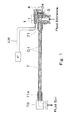
- FIG. 1 is a cross sectional view of a device having a heating/heat-retaining tube according to this embodiment of the present invention
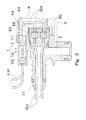
- FIG. 2 is a cross sectional view of a connecting structure between lead wires LW and cord heaters CH in this device
- FIG. 3 is a cross sectional perspective view of the connecting structure between the lead wires LW and the cord heaters CH.
- the device having the heating/heat-retaining tube directly heats fluid or retains the heat of fluid flowing into the tube T by the cord heater CH inserted into the tube T.
- one end of the tube T is externally press-fitted to a bamboo shoot shaped joint section 71 at the fluid entrance side and the other end of the tube T is externally press-fitted to a bamboo shoot shaped joint section 71 a of a tube joint 70 at the fluid exit side.
- the cord heater CH is inserted into the tube T through a hole of the joint section 71 at the fluid entrance side, extended to the joint section 71 a at the fluid exit side, and folded back to return to the joint section 71.
- both ends of the cord heater CH which is led out of the tube T are connected to a power supply P via the lead wires LW.
- the connecting sections t of the cord heaters CH which are led out of the tube T and the lead wires LW which are connected to the power supply P are held in a sealed state in the manner that the connecting sections t are respectively sandwiched by a pair of first sealing members 10 and 11 in wire paths 1.
- intermediate wire paths 2 are provided between the wire paths 1 and the tube T, and the both ends of the cord heater CH are respectively inserted into each of the intermediate wire paths 2 in a sealed state by second sealing members 20.
- a drainage path 3 is provided for removing the fluid such as liquid and gas which is leaked from the intermediate wire paths 2 to outside.
- each of the wire paths 1 is formed in a circular form, with the connecting section t held in a sealed state internally and externally by the cylindrical sealing members 10 and 11 each of which having two circular projections on the inner/outer circumferential surfaces thereof. Since the first sealing members 10 and 11 have two circular projections, even if the sealing property of one of the circular projections, especially the one closer to the liquid, is deteriorated, the fluid-tightness of the connecting section t can be maintained by the other circular projection.
- the above described intermediate wire paths 2 includes an opening section 22 located rear of the joint section 71, a block body 23 and a plug plate 24 respectively inserted into the opening section 22.
- the block body 23 and the plug plate 24 also have holes respectively through which the cord heater CH is inserted.
- the plug plate 24 has a groove having the same size as the block body 23 so that the plug plate 24 can be plugged into the block body 23. Because of the plug plate 24, the block body 23 does not move toward the right side of FIG. 2 even when liquid pressure is applied from the tube T side. The block body 23, thus, is retained in the opening section 23 by the plug plate 24.
- the second sealing members 20 respectively have two circular projections similar to that of the above described sealing members 10 and 11. Since the second sealing member 20 has two circular projections, even when the sealing property of one of the circular projections, especially the one closer to the liquid, is deteriorated, the sealing property of the second sealing member 20 can be maintained by the other circular projection.
- a cover 4 is provided between the wire path 1 and the intermediate wire path 2 to cover the cord heater CH passing through therebetween as shown in FIG. 3 , and the drainage path 3 is provided to the cover 4.
- liquid pressure is applied to the second sealing members 20 from left to right of FIG. 2 .
- the above described second sealing members 20 gradually deteriorate due to heat or other influences as time goes by, there is a possibility that liquid leaks out of the intermediate wire paths 2 into the cover 4 even when the second sealing members 20 are at predetermined positions.
- the leaked liquid in the cover 4 can be discharged to the outside of the cover 4 through the drainage path 3, so that the liquid pressure does not apply to the first sealing members 10 and 11 at all.
- the wire paths 1 are provided at the place higher than where the liquid flows, the first sealing members 11 are not brought into contact with any liquid.
- FIG. 4 is a cross sectional perspective view of a connecting structure between lead wires LW and cord heaters CH of a device having a heating/heat-retaining tube according to a second embodiment of the present invention.
- This device of the second embodiment differs from that of the first embodiment in that the wire paths 1 and the intermediate wire paths 2 are linearly disposed.
- the liquid can be discharged to the outside from the drainage path 3, thereby reliably avoiding an electrically dangerous situation and damage to the entire system due to the leaked fluid in the same manner as the first embodiment.
- the drainage path 3 according to the above described embodiments is merely one example, and any modification can be employed therefor as long as all the liquid, which leaks through the second sealing members 20 due to, for example, deterioration of the second sealing members 20, can be discharged to outside readily.
- the cord heater CH has a configuration in which it extends in one direction from the fluid entrance side to the fluid exit side and then folded back to return to the fluid entrance side, but the configuration is not limited thereto.
- the cord heater CH may be also configured so that it merely extends in one direction (see FIG. 5 ). In this case, there is no need to have more than one wire paths 1 and intermediate wire paths 2.
- this device Since this device has the above described structure, it can prevent fluid such as gas and liquid from leaking into the space where the connecting section t of the lead wire LW and the cord heater CH is provided, thereby reliably avoiding an electrically dangerous situation and a possible damage to the entire system.
Applications Claiming Priority (1)
| Application Number | Priority Date | Filing Date | Title |
|---|---|---|---|
| JP2007197707A JP4823980B2 (ja) | 2007-07-30 | 2007-07-30 | 加熱・保温チューブを有する装置 |
Publications (2)
| Publication Number | Publication Date |
|---|---|
| EP2040510A1 true EP2040510A1 (de) | 2009-03-25 |
| EP2040510B1 EP2040510B1 (de) | 2010-05-19 |
Family
ID=40328909
Family Applications (1)
| Application Number | Title | Priority Date | Filing Date |
|---|---|---|---|
| EP08104916A Active EP2040510B1 (de) | 2007-07-30 | 2008-07-29 | Vorrichtung mit Heizrohr/wärmespeicherndem Rohr |
Country Status (5)
| Country | Link |
|---|---|
| US (1) | US8238733B2 (de) |
| EP (1) | EP2040510B1 (de) |
| JP (1) | JP4823980B2 (de) |
| CN (1) | CN101358680B (de) |
| DE (1) | DE602008001291D1 (de) |
Cited By (3)
| Publication number | Priority date | Publication date | Assignee | Title |
|---|---|---|---|---|
| WO2012076217A1 (de) | 2010-12-08 | 2012-06-14 | Voss Automotive Gmbh | Beheizbare fluidleitung, deren verwendung sowie verfahren zu ihrer herstellung |
| EP2472069A1 (de) | 2010-12-30 | 2012-07-04 | Nuovo Pignone S.p.A. | Leitung für eine Turbomaschine und Verfahren |
| EP2766652B1 (de) | 2011-10-14 | 2017-05-31 | Voss Automotive GmbH | Beheizbare medienleitung mit zumindest einer medienleitung mit zwei leitungsverbindern |
Families Citing this family (36)
| Publication number | Priority date | Publication date | Assignee | Title |
|---|---|---|---|---|
| JP5059631B2 (ja) * | 2008-01-15 | 2012-10-24 | ニッタ株式会社 | 管継手の加熱・保温カバー |
| JP5060970B2 (ja) * | 2008-01-15 | 2012-10-31 | ニッタ株式会社 | 管継手の加熱・保温カバー |
| DE102008022663B4 (de) | 2008-05-07 | 2012-10-31 | Schauenburg Hose Technology Gmbh | Stretch-Schlauch |
| US9505164B2 (en) | 2009-12-30 | 2016-11-29 | Schauenburg Technology Se | Tapered helically reinforced hose and its manufacture |
| US9964238B2 (en) | 2009-01-15 | 2018-05-08 | Globalmed, Inc. | Stretch hose and hose production method |
| FR2943148B1 (fr) * | 2009-03-11 | 2011-03-04 | Vernet | Cartouche chauffante pour un element thermostatique et procede de fabrication correspondant, ainsi que vanne thermostatique comportant une telle cartouche. |
| FR2943149B1 (fr) * | 2009-03-11 | 2013-12-20 | Vernet | Cartouche chauffante et element thermostatique comportant une telle cartouche. |
| JP5720394B2 (ja) | 2011-04-20 | 2015-05-20 | アイシン精機株式会社 | 凍結防止用ドレインホース |
| DE102011102151B4 (de) * | 2011-05-20 | 2022-05-19 | Norma Germany Gmbh | Fluidleitung |
| DE102011102244B4 (de) | 2011-05-20 | 2014-12-31 | Norma Germany Gmbh | Verbinder für eine beheizbare Fluidleitung und beheizbare Fluidleitung |
| DE102011102148A1 (de) | 2011-05-20 | 2012-11-22 | Norma Germany Gmbh | Fluidleitung |
| GB2493719A (en) * | 2011-08-15 | 2013-02-20 | Strix Ltd | Flow heater with temperature sensing and a heat sink |
| DE102011120356A1 (de) | 2011-12-07 | 2013-06-13 | Voss Automotive Gmbh | Konfektionierte Medienleitung und Verfahren zum Konfektionieren einer Medienleitung mit innenliegenden Heizelementen |
| ES2537450T3 (es) * | 2012-09-10 | 2015-06-08 | Norma Germany Gmbh | Conector enchufable |
| DE102013000588A1 (de) * | 2013-01-16 | 2014-07-17 | Voss Automotive Gmbh | Konfektionierte beheizbare Medienleitung, Verwendung einer solchen sowie Verfahren zum Herstellen einer solchen |
| JP2015008042A (ja) | 2013-06-24 | 2015-01-15 | ニッタ株式会社 | 線状部材の防水処理構造 |
| US9568137B2 (en) * | 2013-12-12 | 2017-02-14 | Heat-Line Corporation | Heating cables |
| DE102014102357A1 (de) * | 2014-02-24 | 2015-08-27 | Norma Germany Gmbh | Beheizbare Fluidleitung |
| DE102014102362A1 (de) * | 2014-02-24 | 2015-08-27 | Norma Germany Gmbh | Verbinder für eine Fluidleitung |
| DE102014102353A1 (de) * | 2014-02-24 | 2015-08-27 | Norma Germany Gmbh | Beheizbare Fluidleitung und Verbinder für eine beheizbare Fluidleitung |
| DE102014108494A1 (de) * | 2014-06-17 | 2015-12-17 | Norma Germany Gmbh | Fluidleitung |
| DE102014214690A1 (de) * | 2014-07-25 | 2016-01-28 | Contitech Techno-Chemie Gmbh | Beheizbarer Schlauch |
| DE102014214687A1 (de) * | 2014-07-25 | 2016-01-28 | Contitech Techno-Chemie Gmbh | Beheizbarer Schlauch |
| US10375768B2 (en) * | 2015-03-05 | 2019-08-06 | Heat-Line Corporation | Apparatus and assembly for heating pipes |
| US20170023163A1 (en) * | 2015-07-20 | 2017-01-26 | Norma U.S. Holding Llc | Heated Connector Assembly |
| FR3040950B1 (fr) * | 2015-09-16 | 2017-09-08 | Valeo Systemes Dessuyage | Adaptateur de conduite de liquide et dispositif de distribution de liquide de balais d'essuie-glace de vehicule automobile |
| DE102015220212A1 (de) * | 2015-10-16 | 2017-04-20 | Bayerische Motoren Werke Aktiengesellschaft | Beheizbares Zuleitungsrohr für eine Abgasanlage |
| US11255476B2 (en) | 2015-10-29 | 2022-02-22 | Wagner Spray Tech Corporation | Internally heated modular fluid delivery system |
| CN105697918A (zh) * | 2015-12-10 | 2016-06-22 | 柳州市京阳节能科技研发有限公司 | 多用防冻安全导管设施 |
| CA2973992A1 (en) | 2016-07-21 | 2018-01-21 | Heat-Line Corporation | End seal for heating cable |
| US11014105B2 (en) * | 2016-10-15 | 2021-05-25 | Akurate Dynamics, Llc | Multi-segment heated hose having segment-specific heating means |
| CA3033944C (en) | 2017-01-30 | 2020-02-18 | Globalmed, Inc. | Heated respiratory hose assembly |
| CN109428215B (zh) * | 2017-08-30 | 2020-07-28 | 中国航发商用航空发动机有限责任公司 | 一种导线转接导管 |
| WO2019235558A1 (ja) | 2018-06-07 | 2019-12-12 | 株式会社村田製作所 | 多層基板、電子機器および多層基板の製造方法 |
| US10190716B1 (en) * | 2018-09-11 | 2019-01-29 | Akurate Dynamics, Llc | Heated hose with improved power feedthrough |
| US20200383177A1 (en) * | 2019-05-31 | 2020-12-03 | Graco Minnesota Inc. | Sensor free heated hose |
Citations (5)
| Publication number | Priority date | Publication date | Assignee | Title |
|---|---|---|---|---|
| US2964437A (en) * | 1957-04-19 | 1960-12-13 | Appleton Electric Co | Mineral insulated cable fitting |
| GB2104736A (en) * | 1981-08-31 | 1983-03-09 | Aisin Warner | Connecting and sealing electric cables in an aperture in a housing |
| US6317559B1 (en) * | 1999-09-15 | 2001-11-13 | Du Nyun Kim | Apparatus for sealing the end portion of a hot-water tube in which electric heating wires are inserted |
| JP2005351333A (ja) | 2004-06-09 | 2005-12-22 | Nitta Moore Co | 加熱・保温配管 |
| EP1675241A1 (de) * | 2004-12-23 | 2006-06-28 | MAN Turbomaschinen AG Schweiz | Fluiddichte Leitungsdurchführung |
Family Cites Families (25)
| Publication number | Priority date | Publication date | Assignee | Title |
|---|---|---|---|---|
| US1985280A (en) * | 1931-09-12 | 1934-12-25 | Nat Electric Heating Company I | Electric fluid heater |
| US3270182A (en) * | 1964-03-26 | 1966-08-30 | Hynes Electric Heating Company | High temperature fluid heater |
| US3378282A (en) * | 1965-12-30 | 1968-04-16 | Amp Inc | Tube coupling |
| US3551643A (en) * | 1967-10-12 | 1970-12-29 | Sylvania Electric Prod | Electric heater for heating fluids flowing longitudinally therethrough |
| US3624594A (en) * | 1969-02-14 | 1971-11-30 | Amp Inc | Electrical connector assembly |
| JPS5093455A (de) * | 1973-12-20 | 1975-07-25 | ||
| US3898428A (en) | 1974-03-07 | 1975-08-05 | Universal Oil Prod Co | Electric in line water heating apparatus |
| US3980526A (en) * | 1975-08-11 | 1976-09-14 | Kirschmann John D | Liquid distillation apparatus |
| US4192988A (en) * | 1977-07-11 | 1980-03-11 | Foto-Mark, Inc. | Electrically heated thermal microbial drain barrier |
| US4567350A (en) | 1983-01-06 | 1986-01-28 | Todd Jr Alvin E | Compact high flow rate electric instantaneous water heater |
| US5129034A (en) | 1989-12-08 | 1992-07-07 | Leonard Sydenstricker | On-demand hot water system |
| US5216743A (en) | 1990-05-10 | 1993-06-01 | Seitz David E | Thermo-plastic heat exchanger |
| US5408578A (en) | 1993-01-25 | 1995-04-18 | Bolivar; Luis | Tankless water heater assembly |
| US6142216A (en) * | 1994-07-27 | 2000-11-07 | Bradford White Corporation | Indirect water heater |
| WO1996013963A1 (en) | 1994-10-27 | 1996-05-09 | Watkins Manufacturing Corporation | Cartridge heater system |
| US5892887A (en) | 1997-07-17 | 1999-04-06 | Venturi Technologies, Inc. | Electric water heater with a pair of interconnected heating chambers having concentric copper tube structures |
| DE29715336U1 (de) | 1997-08-27 | 1997-11-06 | Kromberg & Schubert | Heizschlauchanschlußstück |
| US6456785B1 (en) * | 1999-06-01 | 2002-09-24 | Robert Evans | Resistance heating element |
| DE19934346B4 (de) | 1999-07-22 | 2005-10-13 | Rehau Ag + Co. | Vorrichtung zur Befestigung und Abdichtung eines Heizelements in einer Scheibenwaschleitung |
| DE10003042B4 (de) | 2000-01-25 | 2012-03-08 | Stiebel Eltron Gmbh & Co. Kg | Elektrischer Durchlauferhitzer |
| US7190894B2 (en) | 2003-01-03 | 2007-03-13 | Mc3 Technology, Inc. | Energy efficient electric water heater system that provides immediate hot water at a point of use and a method therefor |
| US20040131346A1 (en) | 2003-01-03 | 2004-07-08 | Chamberlain Roland J. | Energy efficient electric water heater system that provides immediate hot water at a point of use and a method therefor |
| US7496285B2 (en) | 2003-07-18 | 2009-02-24 | Liebert Corporation | Multi-pass parallel-tube heat exchanger |
| SE528060C2 (sv) * | 2004-02-25 | 2006-08-22 | Volvo Lastvagnar Ab | Elektriskt uppvärmningsbart kablage |
| JP4029092B2 (ja) | 2004-10-26 | 2008-01-09 | 日本ピラー工業株式会社 | 流体用ヒータ及び流体加熱装置 |
-
2007
- 2007-07-30 JP JP2007197707A patent/JP4823980B2/ja active Active
-
2008
- 2008-06-20 CN CN2008101267368A patent/CN101358680B/zh active Active
- 2008-07-29 DE DE602008001291T patent/DE602008001291D1/de active Active
- 2008-07-29 EP EP08104916A patent/EP2040510B1/de active Active
- 2008-07-30 US US12/182,392 patent/US8238733B2/en active Active - Reinstated
Patent Citations (5)
| Publication number | Priority date | Publication date | Assignee | Title |
|---|---|---|---|---|
| US2964437A (en) * | 1957-04-19 | 1960-12-13 | Appleton Electric Co | Mineral insulated cable fitting |
| GB2104736A (en) * | 1981-08-31 | 1983-03-09 | Aisin Warner | Connecting and sealing electric cables in an aperture in a housing |
| US6317559B1 (en) * | 1999-09-15 | 2001-11-13 | Du Nyun Kim | Apparatus for sealing the end portion of a hot-water tube in which electric heating wires are inserted |
| JP2005351333A (ja) | 2004-06-09 | 2005-12-22 | Nitta Moore Co | 加熱・保温配管 |
| EP1675241A1 (de) * | 2004-12-23 | 2006-06-28 | MAN Turbomaschinen AG Schweiz | Fluiddichte Leitungsdurchführung |
Cited By (7)
| Publication number | Priority date | Publication date | Assignee | Title |
|---|---|---|---|---|
| WO2012076217A1 (de) | 2010-12-08 | 2012-06-14 | Voss Automotive Gmbh | Beheizbare fluidleitung, deren verwendung sowie verfahren zu ihrer herstellung |
| DE102010053737A1 (de) | 2010-12-08 | 2012-06-14 | Voss Automotive Gmbh | Beheizbare Fluidleitung, deren Verwendung sowie Verfahren zu ihrer Herstellung |
| EP2816272A1 (de) | 2010-12-08 | 2014-12-24 | Voss Automotive GmbH | Beheizbare Fluidleitung, deren Verwendung sowie Verfahren zu ihrer Herstellung |
| DE202011110917U1 (de) | 2010-12-08 | 2017-04-12 | Voss Automotive Gmbh | Beheizbare Fluidleitung |
| EP2472069A1 (de) | 2010-12-30 | 2012-07-04 | Nuovo Pignone S.p.A. | Leitung für eine Turbomaschine und Verfahren |
| US8827636B2 (en) | 2010-12-30 | 2014-09-09 | Nuovo Pignone S.P.A | Conduit for turbomachine and method |
| EP2766652B1 (de) | 2011-10-14 | 2017-05-31 | Voss Automotive GmbH | Beheizbare medienleitung mit zumindest einer medienleitung mit zwei leitungsverbindern |
Also Published As
| Publication number | Publication date |
|---|---|
| JP4823980B2 (ja) | 2011-11-24 |
| CN101358680A (zh) | 2009-02-04 |
| CN101358680B (zh) | 2012-07-04 |
| DE602008001291D1 (de) | 2010-07-01 |
| US20090034949A1 (en) | 2009-02-05 |
| US8238733B2 (en) | 2012-08-07 |
| JP2009030771A (ja) | 2009-02-12 |
| EP2040510B1 (de) | 2010-05-19 |
Similar Documents
| Publication | Publication Date | Title |
|---|---|---|
| EP2040510B1 (de) | Vorrichtung mit Heizrohr/wärmespeicherndem Rohr | |
| JP4708412B2 (ja) | 電気的に加熱可能なケーブリング | |
| JP5215286B2 (ja) | 流動可能な媒体、特に、潤滑剤システム内にある潤滑剤の温度に影響を与える装置 | |
| JP2012241902A (ja) | 流体線のための連結器と流体線 | |
| EP2985560B1 (de) | Anschluss- und verteilungsvorrichtung für thermischen steuerschaltkreis von batterien | |
| JP2012241903A (ja) | 流体線 | |
| CA2704492C (en) | Immersion heaters | |
| RU2722197C2 (ru) | Разъем в сборе | |
| KR102429702B1 (ko) | 커넥터를 포함하는 파이프라인과 상기 파이프라인을 동작시키는 방법 | |
| US20090081897A1 (en) | Waterproof electrical connector | |
| JP3943599B2 (ja) | ガスパージ式液没ヒータのパージ管理システム | |
| KR102571373B1 (ko) | 특히 요소 수용액의 통과를 위한 연결 조립체 | |
| ES2918874T3 (es) | Cuerpos de unión, racores, sistema hidráulico para el paso de un fluido entre dos circuitos hidráulicos, procedimiento de montaje asociados | |
| KR100875715B1 (ko) | 발열선이 삽입된 관의 과열 방지용 밀폐장치 | |
| US10590825B2 (en) | Line connector with integrated sensor for measurement of urea solutions | |
| KR100875716B1 (ko) | 관 내부에 설치되는 발열선 연결용 커플링 | |
| JPH07133889A (ja) | 逆流防止コネクター | |
| KR20130131219A (ko) | 압력분산 장치가 구비된 온수관 | |
| KR100985792B1 (ko) | 전열 온수관의 단부 밀폐 구조 및 전열 온수관 시스템 | |
| KR20190127961A (ko) | 플러그를 구비한 가열 배관, 및 이 배관을 동작시키는 방법 | |
| KR200332323Y1 (ko) | 나선관 연결패드 | |
| KR100933794B1 (ko) | 열매체 난방시스템의 난방관 단부장치 | |
| RU2751055C2 (ru) | Излучающий модуль для формирования излучающего корпуса | |
| JP2010073405A (ja) | 漏電検知機能付き電気コネクタ | |
| KR101905797B1 (ko) | 전열 가요성 파이프 |
Legal Events
| Date | Code | Title | Description |
|---|---|---|---|
| PUAI | Public reference made under article 153(3) epc to a published international application that has entered the european phase |
Free format text: ORIGINAL CODE: 0009012 |
|
| AK | Designated contracting states |
Kind code of ref document: A1 Designated state(s): AT BE BG CH CY CZ DE DK EE ES FI FR GB GR HR HU IE IS IT LI LT LU LV MC MT NL NO PL PT RO SE SI SK TR |
|
| AX | Request for extension of the european patent |
Extension state: AL BA MK RS |
|
| 17P | Request for examination filed |
Effective date: 20090925 |
|
| GRAP | Despatch of communication of intention to grant a patent |
Free format text: ORIGINAL CODE: EPIDOSNIGR1 |
|
| AKX | Designation fees paid |
Designated state(s): DE FR SE |
|
| GRAS | Grant fee paid |
Free format text: ORIGINAL CODE: EPIDOSNIGR3 |
|
| GRAA | (expected) grant |
Free format text: ORIGINAL CODE: 0009210 |
|
| AK | Designated contracting states |
Kind code of ref document: B1 Designated state(s): DE FR SE |
|
| REF | Corresponds to: |
Ref document number: 602008001291 Country of ref document: DE Date of ref document: 20100701 Kind code of ref document: P |
|
| REG | Reference to a national code |
Ref country code: SE Ref legal event code: TRGR |
|
| RAP2 | Party data changed (patent owner data changed or rights of a patent transferred) |
Owner name: NITTA CORPORATION |
|
| REG | Reference to a national code |
Ref country code: FR Ref legal event code: TP |
|
| PLBE | No opposition filed within time limit |
Free format text: ORIGINAL CODE: 0009261 |
|
| STAA | Information on the status of an ep patent application or granted ep patent |
Free format text: STATUS: NO OPPOSITION FILED WITHIN TIME LIMIT |
|
| 26N | No opposition filed |
Effective date: 20110222 |
|
| REG | Reference to a national code |
Ref country code: DE Ref legal event code: R097 Ref document number: 602008001291 Country of ref document: DE Effective date: 20110221 |
|
| REG | Reference to a national code |
Ref country code: FR Ref legal event code: PLFP Year of fee payment: 9 |
|
| REG | Reference to a national code |
Ref country code: FR Ref legal event code: PLFP Year of fee payment: 10 |
|
| REG | Reference to a national code |
Ref country code: FR Ref legal event code: PLFP Year of fee payment: 11 |
|
| P01 | Opt-out of the competence of the unified patent court (upc) registered |
Effective date: 20230425 |
|
| PGFP | Annual fee paid to national office [announced via postgrant information from national office to epo] |
Ref country code: SE Payment date: 20230719 Year of fee payment: 16 Ref country code: FR Payment date: 20230725 Year of fee payment: 16 Ref country code: DE Payment date: 20230719 Year of fee payment: 16 |