EP2037181A2 - Haushaltsgerät mit einem Behandlungsraum und einer Stabantenne - Google Patents
Haushaltsgerät mit einem Behandlungsraum und einer Stabantenne Download PDFInfo
- Publication number
- EP2037181A2 EP2037181A2 EP08011567A EP08011567A EP2037181A2 EP 2037181 A2 EP2037181 A2 EP 2037181A2 EP 08011567 A EP08011567 A EP 08011567A EP 08011567 A EP08011567 A EP 08011567A EP 2037181 A2 EP2037181 A2 EP 2037181A2
- Authority
- EP
- European Patent Office
- Prior art keywords
- rod antenna
- stop element
- household appliance
- appliance according
- insulating part
- Prior art date
- Legal status (The legal status is an assumption and is not a legal conclusion. Google has not performed a legal analysis and makes no representation as to the accuracy of the status listed.)
- Granted
Links
Images
Classifications
-
- H—ELECTRICITY
- H01—ELECTRIC ELEMENTS
- H01Q—ANTENNAS, i.e. RADIO AERIALS
- H01Q1/00—Details of, or arrangements associated with, antennas
- H01Q1/12—Supports; Mounting means
- H01Q1/22—Supports; Mounting means by structural association with other equipment or articles
-
- F—MECHANICAL ENGINEERING; LIGHTING; HEATING; WEAPONS; BLASTING
- F24—HEATING; RANGES; VENTILATING
- F24C—DOMESTIC STOVES OR RANGES ; DETAILS OF DOMESTIC STOVES OR RANGES, OF GENERAL APPLICATION
- F24C7/00—Stoves or ranges heated by electric energy
- F24C7/08—Arrangement or mounting of control or safety devices
-
- H—ELECTRICITY
- H01—ELECTRIC ELEMENTS
- H01Q—ANTENNAS, i.e. RADIO AERIALS
- H01Q1/00—Details of, or arrangements associated with, antennas
- H01Q1/12—Supports; Mounting means
- H01Q1/1207—Supports; Mounting means for fastening a rigid aerial element
-
- H—ELECTRICITY
- H01—ELECTRIC ELEMENTS
- H01Q—ANTENNAS, i.e. RADIO AERIALS
- H01Q9/00—Electrically-short antennas having dimensions not more than twice the operating wavelength and consisting of conductive active radiating elements
- H01Q9/04—Resonant antennas
- H01Q9/30—Resonant antennas with feed to end of elongated active element, e.g. unipole
Definitions
- the invention relates to a household appliance with a treatment room and a rod antenna referred to in the preamble of claim 1 Art.
- Such a household appliance is for example from the DE 10 2005 046 012 B3 known.
- Trained as an oven home appliance has a cooking chamber designed as a treatment room.
- the rod antenna has an elongate base body which is delimited in the longitudinal direction by two end-side ends, wherein the rod antenna is held in the treatment space on a wall of the treatment chamber.
- electrical signals between a arranged in the treatment room transmitting or receiving device and the electrical control of the oven can be transmitted wirelessly.
- the invention thus presents the problem of providing a household appliance with a treatment room and a rod antenna, in which the protection of the rod antenna is improved from damage.
- the achievable with the present invention consist in particular in the improved protection of the rod antenna from damage.
- a rod antenna which is mounted only with a front end on the wall of the treatment room, easily damaged by improper operation, namely bent or broken.
- the invention provides a remedy.
- an improved support of the rod antenna is realized on a wall of the treatment chamber of the household appliance by the stop element.
- the rod antenna can expand unhindered relative to the stop element. This is particularly advantageous for household appliances in which operating conditions with higher treatment room temperatures exist.
- the stop element itself is formed as an electrical insulation material.
- the dimensions of the stop element and the rod antenna and their structural design are coordinated with one another such that in each operating state of the household appliance, a contact between the stop element and the rod antenna is effectively prevented.
- the rod antenna or the stop element is surrounded in the region facing the respective other part with an insulating part made of an electrical insulation material. In this way, the stop element and the rod antenna on the type, material and constructive training can be selected within wide limits. At the same time, the wireless signal transmission between the rod antenna and the transmitting or receiving device in the treatment room is not adversely affected.
- the radial distance between the rod antenna and the stop element, with or without insulation part, in the assembled state of the household appliance is less than three times, in particular less than the simple cross-sectional dimension of the rod antenna. This ensures, on the one hand, that sufficient clearance is available to compensate for a different expansion behavior of the components.
- the rod antenna is due to the reduction of the game to the extent absolutely necessary, for example, when mounting a detachable held on the treatment room rod antenna, out better. The same applies to an already mounted or permanently attached to the treatment room wall rod antenna; Due to the better guidance, the above-mentioned advantages are achieved here while at the same time largely fixing the position of the rod antenna.
- the insulating part can be selected according to type, material and arrangement within wide suitable limits.
- the insulating part as a plastic part or a ceramic part, in particular of iron oxide or aluminum oxide formed. Plastics and ceramics are good electrical insulators and inexpensive as standard materials.
- the insulating part arranged on the rod antenna has a centering section for the stop element or the insulating part arranged on the stop element, a centering section for the rod antenna having.
- the assembly and disassembly of the rod antenna is further facilitated in a detachable held on the treatment room wall rod antenna.
- the insulating part has a mounting portion for attachment to the stop element. In this way, the assembly and, in a releasably held on the stop element insulating part, the disassembly of the insulating part is simplified.
- the insulation part on the type, material, arrangement and structural design can be selected within wide suitable limits.
- the material for the insulating part to a high temperature resistance.
- the use of the insulating part in household appliances with higher operating temperatures, such as ovens or ovens with pyrolysis or the like, is possible.
- a particularly advantageous embodiment provides that the stop element is attached to a radiator of the household appliance, in particular a top heat radiator.
- the rod antenna is already arranged in an area of the treatment room, which is intended less affected by user intervention.
- the rod antenna is additionally structurally protected from unwanted or improper user intervention by the radiators.
- rod antenna can be inserted from outside the treatment space through an opening in the wall into the treatment space.
- assembly and disassembly, especially in retrofitted rod antennas is further simplified.
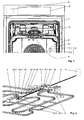
- a first embodiment of a household appliance according to the invention is shown.
- the household appliance is designed here as a baking oven, in whose treatment chamber 2 a heating element 4 designed as a top heat radiator is arranged.
- the radiator 4 is attached via a mounting plate 6 to the rear wall 2.1 of the treatment chamber 2.
- the oven still has an electrical control 8, which is arranged behind a control panel 10 and in Fig. 1 indicated by dashed lines.
- the radiator 4 is controlled to heat the treatment room 2 in a manner known to those skilled in the art via the electrical control 8.
- the oven has a temperature control, wherein a trained as a temperature spike temperature sensor 12 is used to detect the temperature of the cooking product.
- the temperature spit 12 here includes a surface acoustic wave device and is plugged in a known per se in a befindliches in the treatment chamber 2 and not shown here Gargut.
- the signal transmission between the temperature sensor 12 and the electrical control 8 is wireless, so radio technology.
- a rod antenna 14 is attached to the mounting plate 6, which transmits radio signals in a manner known to those skilled in the electrical controller 8 to a receiving device 12.1 of the temperature sensor 12 and / or by a transmitting device 12.2 of the temperature sensor 12 to the electrical controller 8.
- the rod antenna 14 is formed as an elongated base body, so that their extension in the longitudinal direction, ie perpendicular to the rear wall 2.1 of the treatment chamber 2, a multiple of the cross-sectional dimension of the rod antenna 14, that is substantially parallel to the rear wall 2.1.
- the rod antenna 14 is limited in the longitudinal direction by two front ends 14.1 and 14.2, which in Fig. 2 is shown in more detail.
- a fastening body 16 In the fastening body 16, the front end 14.1 is electrically conductively connected to a coaxial line 18, wherein the coaxial line 18 is again electrically connected to the electrical controller 8 for forwarding the electrical signals.
- an external thread 16.1 is formed, which can be screwed for fixing the fastening body 16 in a formed in an opening 6.1 of the mounting plate 6 and not shown in detail internal thread from outside the treatment chamber 2.
- the rod antenna 14 is inserted from the outside through the opening 6.1 of the attached to the rear wall 2.1 mounting plate 6 in the treatment room 2.
- the aforementioned threaded connection between the mounting body 16 and the mounting plate 6 can be made.
- the rod antenna 14 is thus held on the mounting plate 6 via a type of clamping, which only allows the rotation of the rod antenna 14 about its longitudinal axis in a direction of rotation, namely for releasing the threaded connection.
- a stop element 22 designed as a clamp is releasably secured to the upper heat radiator 4 by means of a cross member 20, for example via a screw connection
- an insulating member 24 formed as a high-temperature-resistant ceramic member made of iron oxide is releasably held on the stopper member 22.
- the insulation part 24 has a dumbbell-like outer contour, the middle part of which is designed as a fastening section 24.1 in the form of a circumferential groove.
- the insulating part 24 has a through bore 24.2, whose diameter is about one and a half times as large as the outer diameter of the rod antenna 14.
- the front ends of the insulating part 24 each have a designed as a funnel centering 24.2. Due to the symmetrical design of the insulating part 24 whose assembly is further facilitated.
- the rod antenna 14 is introduced into the treatment space 2 in the manner explained above, it comes into contact with the end face 14.2 in FIG Fig. 2 invisible centering section 24.2. Due to its funnel-like design, the rod antenna 14 is automatically moved in the further movement to the center of the centering portion 24.3 and thus introduced into the through hole 24.2.
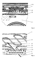
- Fig. 3 shows a second embodiment in the region of the rod antenna 14.
- the insulating member 24 is here not on the stop element 22, but in the region of the front end 14.2 on the rod antenna 14 in the art known manner, for example by gluing, attached.
- the insulating member 24 is here formed as a sleeve, which is in Fig. 4 can be seen more clearly.
- the radial distance between the rod antenna 14 with the insulating member 24 attached thereto and the abutment member 22 is here also less than three times as the cross-sectional dimension of the rod antenna 14.
- the desired effect namely the improved protection of the rod antenna 14 achieved before damage as desired.
- the invention is not limited to the embodiments explained above.
- other household appliances with a treatment room such as other cooking appliances, refrigerators, dishwashers or laundry treatment machines are conceivable.
- the stop element itself is formed as an electrically insulating body.
- an additional isolation part would not necessarily be required.
- the attachment, detachable or insoluble, the individual components can be freely selected within wide appropriate limits.
- the rod antenna can also be attached to any other wall of the treatment room and does not necessarily have to be held on a radiator.
- the rod antenna is not limited to cylindrical body. Other cross-sectional shapes are also possible. Accordingly, the term is also to be understood radially here.
- the insulating part with the rod antenna or the stop element in other known to those skilled and suitable manner, releasably or non-detachably connected.
- the insulating part may also be formed as a coating of the rod antenna or of the stop element.
- the attachment of the rod antenna to the wall of the treatment chamber is designed as a fixed bearing, that is, if all three rotational degrees of freedom are maintained.
- this embodiment has the disadvantage that the assembly of the rod antenna is difficult.
- the rod antenna must be guided for insertion into the stop element by the installer or the user.
- the invention is not limited to use in temperature measuring and / or regulating devices, but generally applicable to all possible types of electrical signal transmissions from treatment rooms of household appliances. For example, pressure, level and weight sensor arrangements or the like would be conceivable.
Landscapes
- Engineering & Computer Science (AREA)
- Chemical & Material Sciences (AREA)
- Combustion & Propulsion (AREA)
- Mechanical Engineering (AREA)
- General Engineering & Computer Science (AREA)
- Support Of Aerials (AREA)
- Constitution Of High-Frequency Heating (AREA)
Abstract
Description
- Die Erfindung betrifft ein Haushaltsgerät mit einem Behandlungsraum und einer Stabantenne der im Oberbegriff des Anspruchs 1 genannten Art.
- Ein derartiges Haushaltsgerät ist beispielsweise aus der
DE 10 2005 046 012 B3 bekannt. Das als Backofen ausgebildete Haushaltsgerät weist einen als Garraum ausgebildeten Behandlungsraum auf. In dem Garraum ist eine Stabantenne angeordnet. Die Stabantenne weist einen länglichen Grundkörper auf, der in Längsrichtung durch zwei stirnseitige Enden begrenzt ist, wobei die Stabantenne in dem Behandlungsraum an einer Wand des Behandlungsraums gehalten ist. Mittels der Stabantenne können elektrische Signale zwischen einer in dem Behandlungsraum angeordneten Sende- oder Empfangseinrichtung und der elektrischen Steuerung des Backofens drahtlos übertragen werden. - Der Erfindung stellt sich somit das Problem ein Haushaltsgerät mit einem Behandlungsraum und einer Stabantenne anzugeben, bei dem der Schutz der Stabantenne vor einer Beschädigung verbessert ist.
- Erfindungsgemäß wird dieses Problem durch ein Haushaltsgerät mit den Merkmalen des Patentanspruchs 1 gelöst. Vorteilhafte Ausgestaltungen und Weiterbildungen der Erfindung ergeben sich aus den nachfolgenden Unteransprüchen.
- Die mit der Erfindung erreichbaren Vorteile bestehen insbesondere in dem verbesserten Schutz der Stabantenne vor Beschädigung. Beispielsweise kann eine Stabantenne, die lediglich mit einem stirnseitigen Ende an der Wand des Behandlungsraums gelagert ist, leicht durch eine unsachgemäße Bedienung beschädigt, nämlich verbogen oder abgebrochen werden. Die Erfindung schafft hier Abhilfe.
- Zwar ist es aus der
DE 34 42 848 C2 bereits bekannt, einen stabförmigen Temperaturfühler an beiden stirnseitigen Enden mit dem Rest des Haushaltsgeräts, hier der Rückwand des Behandlungsraums, und mit einem an dem Behandlungsraum angeordneten Tragbügel, fest zu verbinden. Eine derartige Lagerung hat den Nachteil, dass zum einen Temperaturspannungen aufgrund von sich unterschiedlich ausdehnenden Bauteilen, wie Temperaturfühler, Behandlungsraumwand und Tragbügel, nicht oder nicht vollständig kompensiert werden können. Zum anderen ist hierdurch die Montage und Demontage eines lösbar an dem Behandlungsraum gehaltenen Temperaturfühlers, beispielsweise der nachträgliche Einbau des Temperaturfühlers, erschwert oder gar unmöglich. - Die vorgenannten Nachteile werden durch die Erfindung beseitigt oder zumindest verringert.
- Bei dem erfindungsgemäßen Haushaltsgerät ist durch das Anschlagelement eine verbesserte Halterung der Stabantenne an einer Wand des Behandlungsraums des Haushaltsgeräts verwirklicht. Gleichzeitig kann sich die Stabantenne relativ zu dem Anschlagelement ungehindert ausdehnen. Dies ist insbesondere bei Haushaltsgeräten von Vorteil, bei denen Betriebszustände mit höheren Behandlungsraumtemperaturen existieren.
- Grundsätzlich ist es möglich, dass das Anschlagelement selbst als ein elektrisches Isolationsmaterial ausgebildet ist. Darüber hinaus wäre es auch denkbar, dass die Dimensionen des Anschlagelements und der Stabantenne und deren konstruktive Ausbildung derart aufeinander abgestimmt sind, dass in jedem Betriebszustand des Haushaltsgeräts ein Kontakt zwischen dem Anschlagelement und der Stabantenne wirksam verhindert ist. Vorteilhafterweise ist die Stabantenne oder das Anschlagelement in dem dem jeweils anderen Teil zugewandten Bereich mit einem Isolationsteil aus einem elektrischen Isolationsmaterial umgeben. Auf diese Weise ist das Anschlagelement und die Stabantenne nach Art, Material und konstruktiver Ausbildung in weiten Grenzen wählbar. Gleichzeitig wird die drahtlose Signalübertragung zwischen der Stabantenne und der Sende- oder Empfangseinrichtung in dem Behandlungsraum nicht negativ beeinflusst.
- Eine vorteilhafte Weiterbildung der erfindungsgemäßen Lehre sieht vor, dass der radiale Abstand zwischen der Stabantenne und dem Anschlagelement, mit oder ohne Isolationsteil, in dem zusammengebauten Zustand des Haushaltsgeräts weniger als die dreifache, insbesondere weniger als die einfache Querschnittsausdehnung der Stabantenne beträgt. Hierdurch ist zum einen gewährleistet, dass genügend Spiel vorhanden ist, um ein unterschiedliches Ausdehnungsverhalten der Bauteile zu kompensieren. Zum anderen wird die Stabantenne aufgrund der Verringerung des Spiels auf das unbedingt erforderliche Maß, beispielsweise bei der Montage einer lösbar an dem Behandlungsraum gehaltenen Stabantenne, besser geführt. Gleiches gilt für eine bereits montierte oder unlösbar an der Behandlungsraumwand befestigte Stabantenne; durch die bessere Führung werden hier die oben genannten Vorteile bei gleichzeitig weitgehender Lagefixierung der Stabantenne erreicht.
- Grundsätzlich ist das Isolationsteil nach Art, Material und Anordnung in weiten geeigneten Grenzen wählbar. Vorteilhafterweise ist das Isolationsteil als ein Kunststoffteil oder ein Keramikteil, insbesondere aus Eisenoxid oder Aluminiumoxid, ausgebildet. Kunststoffe und Keramiken sind gute elektrische Isolatoren und als Standardwerkstoffe kostengünstig.
- Eine vorteilhafte Weiterbildung sieht vor, dass das an der Stabantenne angeordnete Isolationsteil einen Zentrierabschnitt für das Anschlagelement oder das an dem Anschlagelement angeordnete Isolationsteil einen Zentrierabschnitt für die Stabantenne aufweist. Hierdurch ist die Montage und Demontage der Stabantenne bei einer lösbar an der Behandlungsraumwand gehaltenen Stabantenne weiter erleichtert.
- Eine andere vorteilhafte Weiterbildung bei an dem Anschlagelement angeordneten Isolationsteil sieht vor, dass das Isolationsteil einen Befestigungsabschnitt zur Befestigung an dem Anschlagelement aufweist. Auf diese Weise ist die Montage und, bei einem lösbar an dem Anschlagelement gehaltenen Isolationsteil, die Demontage des Isolationsteil vereinfacht.
- Grundsätzlich ist das Isolationsteil nach Art, Material, Anordnung und konstruktiver Ausbildung in weiten geeigneten Grenzen wählbar. Vorteilhafterweise weist das Material für das Isolationsteil eine hohe Temperaturbeständigkeit auf. Hierdurch ist die Verwendung des Isolationsteils auch bei Haushaltsgeräten mit höheren Betriebstemperaturen, wie beispielsweise Backöfen oder Backöfen mit Pyrolysebetrieb oder dergleichen, möglich.
- Eine besonders vorteilhafte Weiterbildung sieht vor, dass das Anschlagelement an einem Heizkörper des Haushaltsgeräts, insbesondere einem Oberhitzeheizkörper, befestigt ist. Auf diese Weise ist die Stabantenne bereits in einem Bereich des Behandlungsraums angeordnet, der bestimmungsgemäß weniger durch Benutzereingriffe betroffen ist. Gleichzeitig ist die Stabantenne durch die Heizkörper zusätzlich konstruktiv vor einem ungewünschten oder unsachgemäßen Benutzereingriff geschützt.
- Eine andere vorteilhafte Weiterbildung sieht vor, dass die Stabantenne von außerhalb des Behandlungsraums durch eine Öffnung in der Wand in den Behandlungsraum einführbar ist. Hierdurch ist die Montage und Demontage, insbesondere bei nachträglich montierten Stabantennen weiter vereinfacht.
- Eine vorteilhafte Weiterbildung der vorgenannten Ausführungsform sieht vor, dass die Stabantenne mit einem daran angeordneten Außengewinde in ein an der Öffnung ausgebildetes Innengewinde einschraubbar ist. Hierdurch ist die Herstellung einer lösbaren Verbindung zwischen der Wand des Behandlungsraums und der Stabantenne auf konstruktiv besonders einfache Weise realisiert.
- Ein Ausführungsbeispiel der Erfindung ist in den Zeichnungen rein schematisch dargestellt und wird nachfolgend näher beschrieben. Es zeigt
- Figur 1
- ein erstes Ausführungsbeispiel eines erfindungsgemäßen Haushaltsgeräts in einer teilweisen Darstellung einer perspektivischen Frontansicht,
- Figur 2
- eine perspektivische Teilansicht im Bereich der Stabantenne aus
Fig. 1 , - Figur 3
- ein zweites Ausführungsbeispiel eines erfindungsgemäßen Haushaltsgeräts in einer teilweisen Darstellung einer perspektivischen Frontansicht im Bereich der Stabantenne und
- Figur 4
- eine andere perspektivische Detailansicht der Stabantenne aus
Fig. 3 . - In
Fig. 1 ist ein erstes Ausführungsbeispiel eines erfindungsgemäßen Haushaltsgeräts dargestellt. Das Haushaltsgerät ist hier als ein Backofen ausgebildet, in dessen Behandlungsraum 2 ein als Oberhitzeheizkörper ausgebildeter Heizkörper 4 angeordnet ist. Der Heizkörper 4 ist über eine Montageplatte 6 an der Rückwand 2.1 des Behandlungsraums 2 befestigt. Ferner weist der Backofen noch eine elektrische Steuerung 8 auf, die hinter einer Bedienblende 10 angeordnet und inFig. 1 durch gestrichelte Linien angedeutet ist. Der Heizkörper 4 wird zur Beheizung des Behandlungsraums 2 auf dem Fachmann bekannte Weise über die elektrische Steuerung 8 angesteuert. Hierzu verfügt der Backofen über eine Temperaturregelung, wobei ein als Temperaturspieß ausgebildeter Temperaturfühler 12 zur Erkennung der Garguttemperatur verwendet wird. Der Temperaturspieß 12 beinhaltet hier ein Oberflächenwellenbauelement und ist auf an sich bekannte Weise in ein in dem Behandlungsraum 2 befindliches und hier nicht dargestelltes Gargut eingesteckt. Im Unterschied zu den bekannten Temperaturspießen, die drahtgebunden mit der elektrischen Steuerung in Signalübertragungsverbindung stehen, erfolgt die Signalübertragung zwischen dem Temperaturfühler 12 und der elektrischen Steuerung 8 drahtlos, also funktechnisch. Hierzu ist eine Stabantenne 14 an der Montageplatte 6 befestigt, die Funksignale auf dem Fachmann bekannte Weise von der elektrischen Steuerung 8 an eine Empfangseinrichtung 12.1 des Temperaturfühlers 12 und/oder von einer Sendeeinrichtung 12.2 des Temperaturfühlers 12 an die elektrische Steuerung 8 weiterleitet. - Die Stabantenne 14 ist als ein länglicher Grundkörper ausgebildet, so dass deren Ausdehnung in Längsrichtung, also senkrecht zur Rückwand 2.1 des Behandlungsraums 2, ein Vielfaches der Querschnittsausdehnung der Stabantenne 14, also im Wesentlichen parallel zur Rückwand 2.1 beträgt. Die Stabantenne 14 ist in Längsrichtung durch zwei stirnseitige Enden 14.1 und 14.2 begrenzt, was in
Fig. 2 näher dargestellt ist. Zur Befestigung der Stabantenne 14 an der Montageplatte 6 ist diese auf dem Fachmann bekannte Weise an einem Befestigungskörper 16 gehalten. In dem Befestigungskörper 16 ist das stirnseitige Ende 14.1 mit einer Koaxialleitung 18 elektrisch leitend verbunden, wobei die Koaxialleitung 18 zur Weiterleitung der elektrischen Signale wiederum mit der elektrischen Steuerung 8 elektrisch leitend verbunden ist. An dem Befestigungskörper 16 ist ein Außengewinde 16.1 ausgebildet, das zur Befestigung des Befestigungskörpers 16 in ein in einer Öffnung 6.1 der Montageplatte 6 ausgebildetes und nicht näher dargestelltes Innengewinde von außerhalb des Behandlungsraums 2 eingeschraubt werden kann. Hierdurch ist auch die nachträgliche Montage und Demontage der Stabantenne 14 auf einfache Weise möglich. Die Stabantenne 14 wird von Außen durch die Öffnung 6.1 der an der Rückwand 2.1 befestigten Montageplatte 6 in den Behandlungsraum 2 eingeführt. - Sobald der Befestigungskörper 16 die Montageplatte 6 erreicht hat, kann die vorgenannte Gewindeverbindung zwischen dem Befestigungskörper 16 und der Montageplatte 6 hergestellt werden. Die Stabantenne 14 ist demnach über eine Art Einspannung an der Montageplatte 6 gehalten, die lediglich noch die Rotation der Stabantenne 14 um deren Längsachse in eine Drehrichtung, nämlich zum Lösen der Gewindeverbindung, ermöglicht.
- Um die längliche Stabantenne 14 besser vor einer Beschädigung durch eine unsachgemäße Handhabung, beispielsweise bei der manuellen Reinigung des Behandlungsraums 2, zu schützen, ist hier an dem Oberhitzeheizkörper 4 mittels eines Querträgers 20 ein als Schelle ausgebildetes Anschlagelement 22 lösbar, beispielsweise über eine Schraubverbindung, befestigt. In dem Inneren des Anschlagelements 22 ist hier ein als ein hochtemperaturfestes Keramikteil aus Eisenoxid ausgebildetes Isolationsteil 24 an dem Anschlagelement 22 lösbar gehalten. Hierzu weist das Isolationsteil 24 eine hantelartige Außenkontur auf, deren Mittelteil als Befestigungsabschnitt 24.1 in Form einer umlaufenden Nut ausgebildet ist. Ferner weist das Isolationsteil 24 eine Durchgangsbohrung 24.2 auf, deren Durchmesser etwa eineinhalb mal so groß ist wie der Außendurchmesser der Stabantenne 14. Die stirnseitigen Enden des Isolationsteils 24 weisen jeweils einen als Trichter ausgebildeten Zentrierabschnitt 24.2 auf. Durch die symmetrische Ausbildung des Isolierteils 24 ist dessen Montage weiter erleichtert.
- Wird die Stabantenne 14 auf die oben erläuterte Weise in den Behandlungsraum 2 eingeführt, gelangt diese mit dem stirnseitigen Ende 14.2 in Kontakt mit dem in
Fig. 2 nicht sichtbaren Zentrierabschnitt 24.2. Durch dessen trichterartige Gestaltung wird die Stabantenne 14 bei der weiteren Bewegung automatisch auf das Zentrum des Zentrierabschnitts 24.3 hin bewegt und damit in das Durchgangsloch 24.2 eingeführt. - Nachfolgend wird ein zweites Ausführungsbeispiel des erfindungsgemäßen Haushaltsgeräts erläutert, wobei dem ersten Ausführungsbeispiel entsprechende Bauteile mit gleichen Bezugszeichen versehen sind. Ferner ist die nachfolgende Beschreibung auf die Unterschiede zu dem ersten Ausführungsbeispiel begrenzt.
-
Fig. 3 zeigt ein zweites Ausführungsbeispiel im Bereich der Stabantenne 14. Das Isolationsteil 24 ist hier nicht an dem Anschlagelement 22, sondern in dem Bereich des stirnseitigen Endes 14.2 an der Stabantenne 14 auf dem Fachmann bekannte Weise, beispielsweise durch Klebung, befestigt. Das Isolationsteil 24 ist hier als eine Hülse ausgebildet, was inFig. 4 noch deutlicher zu sehen ist. Der radiale Abstand zwischen der Stabantenne 14 mit dem daran befestigten Isolationsteil 24 und dem Anschlagelement 22 beträgt hier ebenfalls weniger als das dreifache als die Querschnittsausdehnung der Stabantenne 14. Auch bei der einfacheren zweiten Ausführungsform der Erfindung wird die gewünschte Wirkung, nämlich der verbesserte Schutz der Stabantenne 14 vor einer Beschädigung wunschgemäß erreicht. - Die Erfindung ist nicht auf die oben erläuterten Ausführungsbeispiele begrenzt. Beispielsweise sind auch andere Haushaltsgeräte mit einem Behandlungsraum, wie beispielsweise andere Gargeräte, Kühlgeräte, Geschirrspülmaschinen oder Wäschebehandlungsmaschinen denkbar. Auch ist es möglich, dass das Anschlagelement selbst als elektrisch isolierender Körper ausgebildet ist. Hierdurch wäre ein zusätzliches Isolationsteil nicht zwingend erforderlich. Auch die Befestigung, lösbar oder unlösbar, der einzelnen Bauteile ist in weiten geeigneten Grenzen frei wählbar. Die Stabantenne kann auch an jeder anderen Wand des Behandlungsraums befestigt sein und muss nicht zwangsweise an einem Heizkörper gehalten sein. Ferner ist die Stabantenne nicht auf zylindrische Grundkörper beschränkt. Andere Querschnittsformen sind ebenfalls möglich. Entsprechend allgemein ist hier auch der Begriff radial zu verstehen. Darüber hinaus ist es auch denkbar, dass das Isolationsteil mit der Stabantenne oder dem Anschlagelement auf andere dem Fachmann bekannte und geeignete Weise, lösbar oder unlösbar, verbunden ist. Beispielsweise kann das Isolationsteil auch als eine Beschichtung der Stabantenne oder des Anschlagelements ausgebildet sein. Grundsätzlich ist es auch ausreichend, wenn die Befestigung der Stabantenne an der Wand des Behandlungsraums als ein Festlager ausgeführt ist, also wenn alle drei Rotationsfreiheitsgrade erhalten bleiben. Diese Ausführungsform hat jedoch den Nachteil, dass die Montage der Stabantenne erschwert ist. Die Stabantenne muss zur Einführung in das Anschlagelement durch den Monteur oder den Benutzer geführt werden. Die Erfindung ist auch nicht auf die Verwendung bei Temperaturmess- und/oder regeleinrichtungen begrenzt, sondern allgemein auf alle möglichen Arten von elektrischen Signalübertragungen aus Behandlungsräumen von Haushaltsgeräten anwendbar. Beispielsweise wären auch Druck-, Füllstands- und Gewichtssensoranordnungen oder dergleichen denkbar.
Claims (10)
- Haushaltsgerät mit einem Behandlungsraum (2), einer elektrischen Steuerung (8) und mit einer Stabantenne (14), die einen länglichen Grundkörper aufweist, der in Längsrichtung durch zwei stirnseitige Enden (14.1, 14.2) begrenzt ist, wobei die Stabantenne (14) in dem Behandlungsraum (2) an einer Wand (2.1) des Behandlungsraums (2) gehalten ist und mittels der elektrische Signale zwischen einer in dem Behandlungsraum (2) angeordneten Sende- oder Empfangseinrichtung (12.1, 12.2) und der elektrischen Steuerung (8) drahtlos übertragbar sind,
dadurch gekennzeichnet,
dass die Stabantenne (14) in dem zusammengebauten Zustand des Haushaltsgeräts mit einem stirnseitigen Ende (14.1) mittels eines Festlagers oder einer Einspannung (6.1, 16.1) an der Wand (2.1) befestigt ist und im Bereich des anderen stirnseitigen Endes (14.2) in radialer Richtung durch ein an dem Korpus des Haushaltsgeräts befestigtes Anschlagelement (22) mit Spiel eingeschlossen ist. - Haushaltsgerät nach Anspruch 1,
dadurch gekennzeichnet,
dass die Stabantenne (14) oder das Anschlagelement (22) in dem dem jeweils anderen Teil zugewandten Bereich mit einem Isolationsteil (24) aus einem elektrischen Isolationsmaterial umgeben ist. - Haushaltsgerät nach Anspruch 1 oder 2,
dadurch gekennzeichnet,
dass der radiale Abstand zwischen der Stabantenne (14) und dem Anschlagelement (22), mit oder ohne Isolierteil (24), in dem zusammengebauten Zustand des Haushaltsgeräts weniger als die dreifache, insbesondere weniger als die einfache Querschnittsausdehnung der Stabantenne (14) beträgt. - Haushaltsgerät nach Anspruch 3,
dadurch gekennzeichnet,
dass das Isolationsteil (24) als ein Kunststoffteil oder ein Keramikteil, insbesondere aus Eisenoxid oder Aluminiumoxid, ausgebildet ist. - Haushaltsgerät nach Anspruch 3 oder 4,
dadurch gekennzeichnet,
dass das an der Stabantenne angeordnete Isolationsteil einen Zentrierabschnitt für das Anschlagelement oder das an dem Anschlagelement (22) angeordnete Isolationsteil (24) einen Zentrierabschnitt (24.3) für die Stabantenne (14) aufweist. - Haushaltsgerät nach einem der Ansprüche 2 bis 5, wobei das Isolationsteil (24) an dem Anschlagelement (22) angeordnet ist,
dadurch gekennzeichnet,
dass das Isolationsteil (24) einen Befestigungsabschnitt (24.2) zur Befestigung an dem Anschlagelement (22) aufweist. - Haushaltsgerät nach mindestens einem der Ansprüche 2 bis 6,
dadurch gekennzeichnet,
dass das Material für das Isolationsteil (24) eine hohe Temperaturbeständigkeit aufweist. - Haushaltsgerät nach mindestens einem der Ansprüche 1 bis 7,
dadurch gekennzeichnet,
dass das Anschlagelement (22) an einem Heizkörper (4) des Haushaltsgeräts, insbesondere einem Oberhitzeheizkörper, befestigt ist. - Haushaltsgerät nach mindestens einem der Ansprüche 1 bis 8,
dadurch gekennzeichnet,
dass die Stabantenne (14) von außerhalb des Behandlungsraums (2) durch eine Öffnung (6.1) in der Wand (2.1) in den Behandlungsraum (2) einführbar ist. - Haushaltsgerät nach Anspruch 9,
dadurch gekennzeichnet,
dass die Stabantenne (14) mit einem daran angeordneten Außengewinde (16.1) in ein an der Öffnung (6.1) ausgebildetes Innengewinde einschraubbar ist.
Priority Applications (1)
| Application Number | Priority Date | Filing Date | Title |
|---|---|---|---|
| PL08011567T PL2037181T3 (pl) | 2007-09-12 | 2008-06-26 | Urządzenie gospodarstwa domowego z przestrzenią obróbkową i anteną prętową |
Applications Claiming Priority (1)
| Application Number | Priority Date | Filing Date | Title |
|---|---|---|---|
| DE102007043370A DE102007043370B3 (de) | 2007-09-12 | 2007-09-12 | Haushaltsgerät mit einem Behandlungsraum und einer Stabantenne |
Publications (3)
| Publication Number | Publication Date |
|---|---|
| EP2037181A2 true EP2037181A2 (de) | 2009-03-18 |
| EP2037181A3 EP2037181A3 (de) | 2011-03-30 |
| EP2037181B1 EP2037181B1 (de) | 2015-06-10 |
Family
ID=39713447
Family Applications (1)
| Application Number | Title | Priority Date | Filing Date |
|---|---|---|---|
| EP08011567.8A Active EP2037181B1 (de) | 2007-09-12 | 2008-06-26 | Haushaltsgerät mit einem Behandlungsraum und einer Stabantenne |
Country Status (4)
| Country | Link |
|---|---|
| EP (1) | EP2037181B1 (de) |
| DE (1) | DE102007043370B3 (de) |
| ES (1) | ES2543720T3 (de) |
| PL (1) | PL2037181T3 (de) |
Cited By (1)
| Publication number | Priority date | Publication date | Assignee | Title |
|---|---|---|---|---|
| EP2741009A1 (de) * | 2012-12-10 | 2014-06-11 | V-Zug AG | Heiz- und Signalempfangsanordnung und Gargerät mit einer solchen Heiz- und Signalempfangsanordnung |
Families Citing this family (4)
| Publication number | Priority date | Publication date | Assignee | Title |
|---|---|---|---|---|
| DE102011109163B4 (de) * | 2011-08-03 | 2013-07-04 | H. Heinz Messwiderstände GmbH | Ofen mit Abfrageantenne |
| ES2649946T3 (es) * | 2012-05-10 | 2018-01-16 | Miele & Cie. Kg | Aparato doméstico |
| DE102012221015A1 (de) | 2012-11-16 | 2014-05-22 | E.G.O. Elektro-Gerätebau GmbH | Gargerät |
| DE102023201293A1 (de) | 2023-02-15 | 2024-08-22 | BSH Hausgeräte GmbH | Gargerät mit außerhalb des Garraums angeordneter Antenne |
Citations (5)
| Publication number | Priority date | Publication date | Assignee | Title |
|---|---|---|---|---|
| DE3246429A1 (de) | 1982-12-15 | 1984-06-20 | Bosch-Siemens Hausgeräte GmbH, 7000 Stuttgart | Backofen |
| DE3442848A1 (de) | 1984-11-23 | 1986-06-05 | Bosch Siemens Hausgeraete | Backofen |
| DE4228769A1 (de) | 1992-08-28 | 1994-03-03 | Bosch Siemens Hausgeraete | Anordnung eines Temperaturfühlers zur Bratautomatik-Regelung |
| DE19544908A1 (de) | 1995-12-01 | 1997-09-11 | Bosch Siemens Hausgeraete | Schwenkbare Grilleinrichtung |
| DE102005046012B3 (de) | 2005-09-26 | 2006-10-05 | Miele & Cie. Kg | Antennenanordnung für den Signalaustausch zwischen einer Sende- und einer Empfangseinrichtung eines Haushaltsgeräts mit einem beheizbaren Behandlungsraum |
Family Cites Families (1)
| Publication number | Priority date | Publication date | Assignee | Title |
|---|---|---|---|---|
| DE19834644C1 (de) * | 1998-07-31 | 2000-02-03 | Bsh Bosch Siemens Hausgeraete | Backofen mit Temperaturfühler |
-
2007
- 2007-09-12 DE DE102007043370A patent/DE102007043370B3/de not_active Revoked
-
2008
- 2008-06-26 EP EP08011567.8A patent/EP2037181B1/de active Active
- 2008-06-26 ES ES08011567.8T patent/ES2543720T3/es active Active
- 2008-06-26 PL PL08011567T patent/PL2037181T3/pl unknown
Patent Citations (6)
| Publication number | Priority date | Publication date | Assignee | Title |
|---|---|---|---|---|
| DE3246429A1 (de) | 1982-12-15 | 1984-06-20 | Bosch-Siemens Hausgeräte GmbH, 7000 Stuttgart | Backofen |
| DE3442848A1 (de) | 1984-11-23 | 1986-06-05 | Bosch Siemens Hausgeraete | Backofen |
| DE3442848C2 (de) | 1984-11-23 | 1987-02-05 | Bosch-Siemens Hausgeraete Gmbh, 8000 Muenchen | Backofen |
| DE4228769A1 (de) | 1992-08-28 | 1994-03-03 | Bosch Siemens Hausgeraete | Anordnung eines Temperaturfühlers zur Bratautomatik-Regelung |
| DE19544908A1 (de) | 1995-12-01 | 1997-09-11 | Bosch Siemens Hausgeraete | Schwenkbare Grilleinrichtung |
| DE102005046012B3 (de) | 2005-09-26 | 2006-10-05 | Miele & Cie. Kg | Antennenanordnung für den Signalaustausch zwischen einer Sende- und einer Empfangseinrichtung eines Haushaltsgeräts mit einem beheizbaren Behandlungsraum |
Cited By (1)
| Publication number | Priority date | Publication date | Assignee | Title |
|---|---|---|---|---|
| EP2741009A1 (de) * | 2012-12-10 | 2014-06-11 | V-Zug AG | Heiz- und Signalempfangsanordnung und Gargerät mit einer solchen Heiz- und Signalempfangsanordnung |
Also Published As
| Publication number | Publication date |
|---|---|
| EP2037181A3 (de) | 2011-03-30 |
| ES2543720T3 (es) | 2015-08-21 |
| EP2037181B1 (de) | 2015-06-10 |
| PL2037181T3 (pl) | 2015-10-30 |
| DE102007043370B3 (de) | 2008-09-25 |
Similar Documents
| Publication | Publication Date | Title |
|---|---|---|
| EP2037181B1 (de) | Haushaltsgerät mit einem Behandlungsraum und einer Stabantenne | |
| EP1840473B1 (de) | Haushaltsgerät mit einer an einem Traggestell befestigten Teleskopauszugsvorrichtung | |
| DE10354117B4 (de) | Toleranzausgleichselement | |
| EP2847393B1 (de) | Befestigungssystem für wandmontage | |
| DE102019121432A1 (de) | Schellenanordnung mit einer Hitzeschutzeinrichtung | |
| DE202014105503U1 (de) | Winkelverbinder | |
| EP3310129B1 (de) | Gargerät | |
| EP3211324B1 (de) | Lagerbuchse für ein haushaltsgerät mit einem federelement, welches ein abdeckteil zum abdecken einer einfädelöffnung aufweist, baugruppe, haushaltsgerät und verfahren zum herstellen einer lagerbuchse | |
| DE102005058996B3 (de) | Haushaltsgerät mit einer elektrischen Steuerung und einem Zubehörteil | |
| EP1767914A2 (de) | Antennenanordnung für den Signalaustausch zwischen einer Sende- und einer Empfangseinrichtung eines Haushaltsgeräts mit einem beheizbaren Behandlungsraum | |
| DE102014117287A1 (de) | Baueinheit | |
| EP0307629B1 (de) | Elektro-Kochplatte | |
| DE102008011418B3 (de) | Verfahren zum Ausbilden einer Nietverbindung und Nietverbindung | |
| DE202005010186U1 (de) | Halteeinrichtung sowie Halteelement hierfür | |
| EP4000462B1 (de) | Haushaltsgerätevorrichtung, haushaltsgerät mit einer solchen haushaltsgerätevorrichtung und verfahren zur montage einer solchen haushaltsgerätevorrichtung | |
| DE10314587B4 (de) | Gargerät | |
| EP3258121B1 (de) | Befestigungsvorrichtung zur befestigung zweier bauteile, insbesondere möbelteile oder möbelteilkomponenten, aneinander | |
| EP1070904B1 (de) | Montagewinkel | |
| EP3346172A1 (de) | Brandschutzvorrichtung | |
| DE4013074A1 (de) | Einstellbares geraet, insbesondere elektrisches schalt-, steuer- oder regelgeraet | |
| WO2009141421A2 (de) | Elektrisches haushaltsgerät | |
| EP2275746A2 (de) | Wärmeisolierungskörper, Satz aus mehreren Wärmeisolierungskörpern, Haushaltsofen mit einer Wärmeisolierung und Verfahren zum Anbringen einer Wärmeisolierung | |
| WO2012083941A1 (de) | Montageanordnung für einen türbetätiger zur verbindungsmittellosen montage auf einer montageplatte | |
| EP1113555A1 (de) | Kabeldurchführung | |
| EP4374739A1 (de) | System mit einem haushaltsgerät und einem möbel |
Legal Events
| Date | Code | Title | Description |
|---|---|---|---|
| PUAI | Public reference made under article 153(3) epc to a published international application that has entered the european phase |
Free format text: ORIGINAL CODE: 0009012 |
|
| AK | Designated contracting states |
Kind code of ref document: A2 Designated state(s): AT BE BG CH CY CZ DE DK EE ES FI FR GB GR HR HU IE IS IT LI LT LU LV MC MT NL NO PL PT RO SE SI SK TR |
|
| AX | Request for extension of the european patent |
Extension state: AL BA MK RS |
|
| PUAL | Search report despatched |
Free format text: ORIGINAL CODE: 0009013 |
|
| AK | Designated contracting states |
Kind code of ref document: A3 Designated state(s): AT BE BG CH CY CZ DE DK EE ES FI FR GB GR HR HU IE IS IT LI LT LU LV MC MT NL NO PL PT RO SE SI SK TR |
|
| AX | Request for extension of the european patent |
Extension state: AL BA MK RS |
|
| 17P | Request for examination filed |
Effective date: 20110929 |
|
| AKX | Designation fees paid |
Designated state(s): AT BE BG CH CY CZ DE DK EE ES FI FR GB GR HR HU IE IS IT LI LT LU LV MC MT NL NO PL PT RO SE SI SK TR |
|
| TPAC | Observations filed by third parties |
Free format text: ORIGINAL CODE: EPIDOSNTIPA |
|
| 17Q | First examination report despatched |
Effective date: 20120417 |
|
| REG | Reference to a national code |
Ref country code: DE Ref legal event code: R079 Ref document number: 502008013046 Country of ref document: DE Free format text: PREVIOUS MAIN CLASS: F24C0007080000 Ipc: H01Q0009300000 |
|
| RIC1 | Information provided on ipc code assigned before grant |
Ipc: F24C 7/08 20060101ALI20140902BHEP Ipc: H01Q 1/12 20060101ALI20140902BHEP Ipc: H01Q 1/22 20060101ALI20140902BHEP Ipc: H01Q 9/30 20060101AFI20140902BHEP |
|
| GRAP | Despatch of communication of intention to grant a patent |
Free format text: ORIGINAL CODE: EPIDOSNIGR1 |
|
| INTG | Intention to grant announced |
Effective date: 20150206 |
|
| GRAS | Grant fee paid |
Free format text: ORIGINAL CODE: EPIDOSNIGR3 |
|
| GRAA | (expected) grant |
Free format text: ORIGINAL CODE: 0009210 |
|
| AK | Designated contracting states |
Kind code of ref document: B1 Designated state(s): AT BE BG CH CY CZ DE DK EE ES FI FR GB GR HR HU IE IS IT LI LT LU LV MC MT NL NO PL PT RO SE SI SK TR |
|
| REG | Reference to a national code |
Ref country code: GB Ref legal event code: FG4D Free format text: NOT ENGLISH |
|
| REG | Reference to a national code |
Ref country code: CH Ref legal event code: EP |
|
| REG | Reference to a national code |
Ref country code: DE Ref legal event code: R084 Ref document number: 502008013046 Country of ref document: DE |
|
| REG | Reference to a national code |
Ref country code: AT Ref legal event code: REF Ref document number: 731235 Country of ref document: AT Kind code of ref document: T Effective date: 20150715 |
|
| REG | Reference to a national code |
Ref country code: DE Ref legal event code: R096 Ref document number: 502008013046 Country of ref document: DE |
|
| REG | Reference to a national code |
Ref country code: IE Ref legal event code: FG4D Free format text: LANGUAGE OF EP DOCUMENT: GERMAN |
|
| REG | Reference to a national code |
Ref country code: ES Ref legal event code: GC2A Effective date: 20150729 |
|
| REG | Reference to a national code |
Ref country code: ES Ref legal event code: FG2A Ref document number: 2543720 Country of ref document: ES Kind code of ref document: T3 Effective date: 20150821 |
|
| PG25 | Lapsed in a contracting state [announced via postgrant information from national office to epo] |
Ref country code: NO Free format text: LAPSE BECAUSE OF FAILURE TO SUBMIT A TRANSLATION OF THE DESCRIPTION OR TO PAY THE FEE WITHIN THE PRESCRIBED TIME-LIMIT Effective date: 20150910 Ref country code: FI Free format text: LAPSE BECAUSE OF FAILURE TO SUBMIT A TRANSLATION OF THE DESCRIPTION OR TO PAY THE FEE WITHIN THE PRESCRIBED TIME-LIMIT Effective date: 20150610 Ref country code: LT Free format text: LAPSE BECAUSE OF FAILURE TO SUBMIT A TRANSLATION OF THE DESCRIPTION OR TO PAY THE FEE WITHIN THE PRESCRIBED TIME-LIMIT Effective date: 20150610 |
|
| REG | Reference to a national code |
Ref country code: PL Ref legal event code: T3 Ref country code: PL Ref legal event code: LICE Effective date: 20150730 |
|
| REG | Reference to a national code |
Ref country code: NL Ref legal event code: MP Effective date: 20150610 |
|
| PG25 | Lapsed in a contracting state [announced via postgrant information from national office to epo] |
Ref country code: GR Free format text: LAPSE BECAUSE OF FAILURE TO SUBMIT A TRANSLATION OF THE DESCRIPTION OR TO PAY THE FEE WITHIN THE PRESCRIBED TIME-LIMIT Effective date: 20150911 Ref country code: LV Free format text: LAPSE BECAUSE OF FAILURE TO SUBMIT A TRANSLATION OF THE DESCRIPTION OR TO PAY THE FEE WITHIN THE PRESCRIBED TIME-LIMIT Effective date: 20150610 Ref country code: BG Free format text: LAPSE BECAUSE OF FAILURE TO SUBMIT A TRANSLATION OF THE DESCRIPTION OR TO PAY THE FEE WITHIN THE PRESCRIBED TIME-LIMIT Effective date: 20150910 |
|
| PG25 | Lapsed in a contracting state [announced via postgrant information from national office to epo] |
Ref country code: EE Free format text: LAPSE BECAUSE OF FAILURE TO SUBMIT A TRANSLATION OF THE DESCRIPTION OR TO PAY THE FEE WITHIN THE PRESCRIBED TIME-LIMIT Effective date: 20150610 |
|
| REG | Reference to a national code |
Ref country code: CH Ref legal event code: PL |
|
| PG25 | Lapsed in a contracting state [announced via postgrant information from national office to epo] |
Ref country code: RO Free format text: LAPSE BECAUSE OF NON-PAYMENT OF DUE FEES Effective date: 20150610 Ref country code: SK Free format text: LAPSE BECAUSE OF FAILURE TO SUBMIT A TRANSLATION OF THE DESCRIPTION OR TO PAY THE FEE WITHIN THE PRESCRIBED TIME-LIMIT Effective date: 20150610 Ref country code: IS Free format text: LAPSE BECAUSE OF FAILURE TO SUBMIT A TRANSLATION OF THE DESCRIPTION OR TO PAY THE FEE WITHIN THE PRESCRIBED TIME-LIMIT Effective date: 20151010 Ref country code: PT Free format text: LAPSE BECAUSE OF FAILURE TO SUBMIT A TRANSLATION OF THE DESCRIPTION OR TO PAY THE FEE WITHIN THE PRESCRIBED TIME-LIMIT Effective date: 20151012 Ref country code: CZ Free format text: LAPSE BECAUSE OF FAILURE TO SUBMIT A TRANSLATION OF THE DESCRIPTION OR TO PAY THE FEE WITHIN THE PRESCRIBED TIME-LIMIT Effective date: 20150610 |
|
| REG | Reference to a national code |
Ref country code: DE Ref legal event code: R097 Ref document number: 502008013046 Country of ref document: DE |
|
| REG | Reference to a national code |
Ref country code: IE Ref legal event code: MM4A |
|
| PG25 | Lapsed in a contracting state [announced via postgrant information from national office to epo] |
Ref country code: MC Free format text: LAPSE BECAUSE OF FAILURE TO SUBMIT A TRANSLATION OF THE DESCRIPTION OR TO PAY THE FEE WITHIN THE PRESCRIBED TIME-LIMIT Effective date: 20150610 |
|
| PLBE | No opposition filed within time limit |
Free format text: ORIGINAL CODE: 0009261 |
|
| STAA | Information on the status of an ep patent application or granted ep patent |
Free format text: STATUS: NO OPPOSITION FILED WITHIN TIME LIMIT |
|
| PG25 | Lapsed in a contracting state [announced via postgrant information from national office to epo] |
Ref country code: CH Free format text: LAPSE BECAUSE OF NON-PAYMENT OF DUE FEES Effective date: 20150630 Ref country code: LI Free format text: LAPSE BECAUSE OF NON-PAYMENT OF DUE FEES Effective date: 20150630 Ref country code: DK Free format text: LAPSE BECAUSE OF FAILURE TO SUBMIT A TRANSLATION OF THE DESCRIPTION OR TO PAY THE FEE WITHIN THE PRESCRIBED TIME-LIMIT Effective date: 20150610 Ref country code: IE Free format text: LAPSE BECAUSE OF NON-PAYMENT OF DUE FEES Effective date: 20150626 |
|
| 26N | No opposition filed |
Effective date: 20160311 |
|
| GBPC | Gb: european patent ceased through non-payment of renewal fee |
Effective date: 20150910 |
|
| PG25 | Lapsed in a contracting state [announced via postgrant information from national office to epo] |
Ref country code: SI Free format text: LAPSE BECAUSE OF FAILURE TO SUBMIT A TRANSLATION OF THE DESCRIPTION OR TO PAY THE FEE WITHIN THE PRESCRIBED TIME-LIMIT Effective date: 20150610 |
|
| REG | Reference to a national code |
Ref country code: FR Ref legal event code: PLFP Year of fee payment: 9 |
|
| PG25 | Lapsed in a contracting state [announced via postgrant information from national office to epo] |
Ref country code: GB Free format text: LAPSE BECAUSE OF NON-PAYMENT OF DUE FEES Effective date: 20150910 |
|
| REG | Reference to a national code |
Ref country code: AT Ref legal event code: MM01 Ref document number: 731235 Country of ref document: AT Kind code of ref document: T Effective date: 20150626 |
|
| PG25 | Lapsed in a contracting state [announced via postgrant information from national office to epo] |
Ref country code: AT Free format text: LAPSE BECAUSE OF NON-PAYMENT OF DUE FEES Effective date: 20150626 |
|
| PG25 | Lapsed in a contracting state [announced via postgrant information from national office to epo] |
Ref country code: MT Free format text: LAPSE BECAUSE OF FAILURE TO SUBMIT A TRANSLATION OF THE DESCRIPTION OR TO PAY THE FEE WITHIN THE PRESCRIBED TIME-LIMIT Effective date: 20150610 |
|
| PG25 | Lapsed in a contracting state [announced via postgrant information from national office to epo] |
Ref country code: HU Free format text: LAPSE BECAUSE OF FAILURE TO SUBMIT A TRANSLATION OF THE DESCRIPTION OR TO PAY THE FEE WITHIN THE PRESCRIBED TIME-LIMIT; INVALID AB INITIO Effective date: 20080626 |
|
| PG25 | Lapsed in a contracting state [announced via postgrant information from national office to epo] |
Ref country code: SE Free format text: LAPSE BECAUSE OF FAILURE TO SUBMIT A TRANSLATION OF THE DESCRIPTION OR TO PAY THE FEE WITHIN THE PRESCRIBED TIME-LIMIT Effective date: 20150610 Ref country code: CY Free format text: LAPSE BECAUSE OF FAILURE TO SUBMIT A TRANSLATION OF THE DESCRIPTION OR TO PAY THE FEE WITHIN THE PRESCRIBED TIME-LIMIT Effective date: 20150610 Ref country code: NL Free format text: LAPSE BECAUSE OF FAILURE TO SUBMIT A TRANSLATION OF THE DESCRIPTION OR TO PAY THE FEE WITHIN THE PRESCRIBED TIME-LIMIT Effective date: 20150610 |
|
| REG | Reference to a national code |
Ref country code: FR Ref legal event code: PLFP Year of fee payment: 10 |
|
| PG25 | Lapsed in a contracting state [announced via postgrant information from national office to epo] |
Ref country code: BE Free format text: LAPSE BECAUSE OF NON-PAYMENT OF DUE FEES Effective date: 20150630 Ref country code: HR Free format text: LAPSE BECAUSE OF FAILURE TO SUBMIT A TRANSLATION OF THE DESCRIPTION OR TO PAY THE FEE WITHIN THE PRESCRIBED TIME-LIMIT Effective date: 20150610 |
|
| PG25 | Lapsed in a contracting state [announced via postgrant information from national office to epo] |
Ref country code: LU Free format text: LAPSE BECAUSE OF NON-PAYMENT OF DUE FEES Effective date: 20150626 |
|
| REG | Reference to a national code |
Ref country code: FR Ref legal event code: PLFP Year of fee payment: 11 |
|
| P01 | Opt-out of the competence of the unified patent court (upc) registered |
Effective date: 20230529 |
|
| PGFP | Annual fee paid to national office [announced via postgrant information from national office to epo] |
Ref country code: TR Payment date: 20240613 Year of fee payment: 17 |
|
| PGFP | Annual fee paid to national office [announced via postgrant information from national office to epo] |
Ref country code: IT Payment date: 20240619 Year of fee payment: 17 |
|
| PGFP | Annual fee paid to national office [announced via postgrant information from national office to epo] |
Ref country code: PL Payment date: 20250520 Year of fee payment: 18 |
|
| PGFP | Annual fee paid to national office [announced via postgrant information from national office to epo] |
Ref country code: ES Payment date: 20250710 Year of fee payment: 18 |
|
| PG25 | Lapsed in a contracting state [announced via postgrant information from national office to epo] |
Ref country code: IT Free format text: LAPSE BECAUSE OF NON-PAYMENT OF DUE FEES Effective date: 20250626 |
|
| PGFP | Annual fee paid to national office [announced via postgrant information from national office to epo] |
Ref country code: DE Payment date: 20260630 Year of fee payment: 19 |
|
| PGFP | Annual fee paid to national office [announced via postgrant information from national office to epo] |
Ref country code: FR Payment date: 20260622 Year of fee payment: 19 |