EP2037152A2 - Getriebe und variable radial expandierende Federkupplungsanordnung - Google Patents
Getriebe und variable radial expandierende Federkupplungsanordnung Download PDFInfo
- Publication number
- EP2037152A2 EP2037152A2 EP08162397A EP08162397A EP2037152A2 EP 2037152 A2 EP2037152 A2 EP 2037152A2 EP 08162397 A EP08162397 A EP 08162397A EP 08162397 A EP08162397 A EP 08162397A EP 2037152 A2 EP2037152 A2 EP 2037152A2
- Authority
- EP
- European Patent Office
- Prior art keywords
- gear
- clutch
- transmission
- shaft member
- spring
- Prior art date
- Legal status (The legal status is an assumption and is not a legal conclusion. Google has not performed a legal analysis and makes no representation as to the accuracy of the status listed.)
- Granted
Links
- 230000005540 biological transmission Effects 0.000 title claims abstract description 49
- 238000005096 rolling process Methods 0.000 claims abstract description 72
- 230000009467 reduction Effects 0.000 claims description 8
- 230000007423 decrease Effects 0.000 claims description 5
- 238000010586 diagram Methods 0.000 description 9
- 230000037361 pathway Effects 0.000 description 4
- 230000000712 assembly Effects 0.000 description 3
- 238000000429 assembly Methods 0.000 description 3
- 230000008901 benefit Effects 0.000 description 1
- 230000008859 change Effects 0.000 description 1
- 230000003247 decreasing effect Effects 0.000 description 1
- 238000000227 grinding Methods 0.000 description 1
- 238000004519 manufacturing process Methods 0.000 description 1
- 239000000463 material Substances 0.000 description 1
- 230000007246 mechanism Effects 0.000 description 1
- 238000000034 method Methods 0.000 description 1
- 238000003801 milling Methods 0.000 description 1
- 230000004048 modification Effects 0.000 description 1
- 238000012986 modification Methods 0.000 description 1
- 239000012255 powdered metal Substances 0.000 description 1
- 230000007704 transition Effects 0.000 description 1
Images


Classifications
-
- F—MECHANICAL ENGINEERING; LIGHTING; HEATING; WEAPONS; BLASTING
- F16—ENGINEERING ELEMENTS AND UNITS; GENERAL MEASURES FOR PRODUCING AND MAINTAINING EFFECTIVE FUNCTIONING OF MACHINES OR INSTALLATIONS; THERMAL INSULATION IN GENERAL
- F16D—COUPLINGS FOR TRANSMITTING ROTATION; CLUTCHES; BRAKES
- F16D7/00—Slip couplings, e.g. slipping on overload, for absorbing shock
- F16D7/002—Slip couplings, e.g. slipping on overload, for absorbing shock the torque being transmitted and limited by yielding of an elastomeric race
-
- F—MECHANICAL ENGINEERING; LIGHTING; HEATING; WEAPONS; BLASTING
- F16—ENGINEERING ELEMENTS AND UNITS; GENERAL MEASURES FOR PRODUCING AND MAINTAINING EFFECTIVE FUNCTIONING OF MACHINES OR INSTALLATIONS; THERMAL INSULATION IN GENERAL
- F16D—COUPLINGS FOR TRANSMITTING ROTATION; CLUTCHES; BRAKES
- F16D43/00—Automatic clutches
- F16D43/02—Automatic clutches actuated entirely mechanically
- F16D43/20—Automatic clutches actuated entirely mechanically controlled by torque, e.g. overload-release clutches, slip-clutches with means by which torque varies the clutching pressure
- F16D43/202—Automatic clutches actuated entirely mechanically controlled by torque, e.g. overload-release clutches, slip-clutches with means by which torque varies the clutching pressure of the ratchet type
- F16D43/204—Automatic clutches actuated entirely mechanically controlled by torque, e.g. overload-release clutches, slip-clutches with means by which torque varies the clutching pressure of the ratchet type with intermediate balls or rollers
- F16D43/208—Automatic clutches actuated entirely mechanically controlled by torque, e.g. overload-release clutches, slip-clutches with means by which torque varies the clutching pressure of the ratchet type with intermediate balls or rollers moving radially between engagement and disengagement
-
- F—MECHANICAL ENGINEERING; LIGHTING; HEATING; WEAPONS; BLASTING
- F16—ENGINEERING ELEMENTS AND UNITS; GENERAL MEASURES FOR PRODUCING AND MAINTAINING EFFECTIVE FUNCTIONING OF MACHINES OR INSTALLATIONS; THERMAL INSULATION IN GENERAL
- F16D—COUPLINGS FOR TRANSMITTING ROTATION; CLUTCHES; BRAKES
- F16D7/00—Slip couplings, e.g. slipping on overload, for absorbing shock
- F16D7/04—Slip couplings, e.g. slipping on overload, for absorbing shock of the ratchet type
- F16D7/06—Slip couplings, e.g. slipping on overload, for absorbing shock of the ratchet type with intermediate balls or rollers
- F16D7/10—Slip couplings, e.g. slipping on overload, for absorbing shock of the ratchet type with intermediate balls or rollers moving radially between engagement and disengagement
-
- F—MECHANICAL ENGINEERING; LIGHTING; HEATING; WEAPONS; BLASTING
- F16—ENGINEERING ELEMENTS AND UNITS; GENERAL MEASURES FOR PRODUCING AND MAINTAINING EFFECTIVE FUNCTIONING OF MACHINES OR INSTALLATIONS; THERMAL INSULATION IN GENERAL
- F16H—GEARING
- F16H35/00—Gearings or mechanisms with other special functional features
- F16H35/10—Arrangements or devices for absorbing overload or preventing damage by overload
-
- F—MECHANICAL ENGINEERING; LIGHTING; HEATING; WEAPONS; BLASTING
- F16—ENGINEERING ELEMENTS AND UNITS; GENERAL MEASURES FOR PRODUCING AND MAINTAINING EFFECTIVE FUNCTIONING OF MACHINES OR INSTALLATIONS; THERMAL INSULATION IN GENERAL
- F16H—GEARING
- F16H3/00—Toothed gearings for conveying rotary motion with variable gear ratio or for reversing rotary motion
- F16H3/02—Toothed gearings for conveying rotary motion with variable gear ratio or for reversing rotary motion without gears having orbital motion
- F16H3/20—Toothed gearings for conveying rotary motion with variable gear ratio or for reversing rotary motion without gears having orbital motion exclusively or essentially using gears that can be moved out of gear
- F16H3/22—Toothed gearings for conveying rotary motion with variable gear ratio or for reversing rotary motion without gears having orbital motion exclusively or essentially using gears that can be moved out of gear with gears shiftable only axially
- F16H3/30—Toothed gearings for conveying rotary motion with variable gear ratio or for reversing rotary motion without gears having orbital motion exclusively or essentially using gears that can be moved out of gear with gears shiftable only axially with driving and driven shafts not coaxial
- F16H3/32—Toothed gearings for conveying rotary motion with variable gear ratio or for reversing rotary motion without gears having orbital motion exclusively or essentially using gears that can be moved out of gear with gears shiftable only axially with driving and driven shafts not coaxial and an additional shaft
-
- Y—GENERAL TAGGING OF NEW TECHNOLOGICAL DEVELOPMENTS; GENERAL TAGGING OF CROSS-SECTIONAL TECHNOLOGIES SPANNING OVER SEVERAL SECTIONS OF THE IPC; TECHNICAL SUBJECTS COVERED BY FORMER USPC CROSS-REFERENCE ART COLLECTIONS [XRACs] AND DIGESTS
- Y10—TECHNICAL SUBJECTS COVERED BY FORMER USPC
- Y10T—TECHNICAL SUBJECTS COVERED BY FORMER US CLASSIFICATION
- Y10T74/00—Machine element or mechanism
- Y10T74/19—Gearing
- Y10T74/19219—Interchangeably locked
- Y10T74/19242—Combined gear and clutch
-
- Y—GENERAL TAGGING OF NEW TECHNOLOGICAL DEVELOPMENTS; GENERAL TAGGING OF CROSS-SECTIONAL TECHNOLOGIES SPANNING OVER SEVERAL SECTIONS OF THE IPC; TECHNICAL SUBJECTS COVERED BY FORMER USPC CROSS-REFERENCE ART COLLECTIONS [XRACs] AND DIGESTS
- Y10—TECHNICAL SUBJECTS COVERED BY FORMER USPC
- Y10T—TECHNICAL SUBJECTS COVERED BY FORMER US CLASSIFICATION
- Y10T74/00—Machine element or mechanism
- Y10T74/19—Gearing
- Y10T74/19219—Interchangeably locked
- Y10T74/19251—Control mechanism
- Y10T74/19256—Automatic
- Y10T74/19274—Automatic torque responsive
-
- Y—GENERAL TAGGING OF NEW TECHNOLOGICAL DEVELOPMENTS; GENERAL TAGGING OF CROSS-SECTIONAL TECHNOLOGIES SPANNING OVER SEVERAL SECTIONS OF THE IPC; TECHNICAL SUBJECTS COVERED BY FORMER USPC CROSS-REFERENCE ART COLLECTIONS [XRACs] AND DIGESTS
- Y10—TECHNICAL SUBJECTS COVERED BY FORMER USPC
- Y10T—TECHNICAL SUBJECTS COVERED BY FORMER US CLASSIFICATION
- Y10T74/00—Machine element or mechanism
- Y10T74/19—Gearing
- Y10T74/19219—Interchangeably locked
- Y10T74/19358—Laterally slidable gears
Definitions
- the present teachings relate to a radially expanding spring clutch that can be used in a transmission to reduce torque transmitted therethrough when a threshold torque is surpassed.
- the overdrive clutch When a threshold torque is surpassed, the overdrive clutch can open and reduce or eliminate the torque that is transmitted through the clutch. By reducing the torque, the user can continue to hold the tool and/or can avoid possible damage to the transmission. Notwithstanding, the overdrive clutch can be relatively large, it typically includes many components and can be relatively complex. A relatively high part count and associated complexity can add additional costs to the tool.
- the present teachings generally include a transmission that includes a shaft member having a continuous cylindrical surface portion longitudinally disposed next to a cylindrical outer surface portion interrupted by longitudinal grooves.
- a first gear assembly has a first clutch spring that holds a first set of rolling members between lobes that extend from a first output gear.
- a second gear assembly has a second clutch spring that holds a second set of rolling members between lobes that extend from a second output gear.
- the first gear assembly and the second gear assembly are configured to move longitudinally along the shaft member to a position where at least one of the first gear assembly and the second gear assembly is engaged for rotation with the shaft member when a value of torque at the shaft member is below a torque threshold value.
- the present teachings generally pertain to a powered drill or driver 10.
- the drill or driver 10 can be a right angle drill 12, as shown in FIG. 1 .
- the right angle drill 12 can include a housing 14 having a handle 16 from which a trigger assembly 18 extends.
- a secondary handle 20 can also extend from the housing 14 to provide, for example, an additional hand hold for the user to hold the right angle drill 12.
- the housing 14 can contain, for example, a motor 22 that can drive a transmission 24 that ultimately provides a torque output to a chuck assembly 26.
- the chuck assembly 26 can be attached to an end of a spindle shaft member 28, as shown in FIGS. 7 and 8 .
- the trigger assembly 18 can be retracted to energize the motor 22 to drive the transmission 24.
- the chuck assembly 26 can be opened and closed to accept various tool bits.
- the drill or driver 10 is but one example in which the transmission 24 can be used.
- the transmission 24 can be used in various power tools, consumer goods and/or any device with rotary power where the ability to limit and control torque can be a benefit. Examples include, but are not limited to, saws, yard tools, vacuums, routers, etc.
- a shifting mechanism 30 can be actuated by the user to change the transmission 24 of the right angle drive drill 12 between a first output speed and a second output speed.
- the first output speed can be a low speed condition.
- the second output speed can be a high speed condition.
- a gear ratio can be established between the low speed condition and the high speed condition that is about four to one.
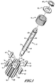
- the present teachings can also include a radially expanding clutch assembly 50 that can have a shaft member 52.
- the shaft member 52 can receive an input torque and a gear member 54 can provide an output torque.
- the radially expanding clutch assembly 50 can also include a clutch spring 56, a clutch washer 58 and/or a retaining ring 60, which can act to contain rolling members 62 within the radially expanding clutch assembly 50.
- the radially expanding clutch assembly 50 can be implemented with the transmission 24.
- the shaft member 52 can include four longitudinal grooves 64 that are formed within the shaft member 52.
- the four longitudinal grooves 64 can interrupt an outer cylindrical surface 66 of the shaft member 52 and thus can form radial portions 68 between the four longitudinal grooves 64. These radial portions 68 can continue an outer surface contour of the outer cylindrical surface 66 of the shaft member 52.
- the rolling members 62 in this example shown as pins 70, can reside within the longitudinal grooves 64 of the shaft member 52.
- a curvature 72 of the longitudinal grooves 64 can be complimentary to a curvature 74 of one or more suitable rolling members 62 such as the pins 70.
- the curvature 72 can define a substantially flat portion (i.e., little or no curvature) on which the rolling members 62 can reside such as the planes 210, as shown in FIGS. 9, 10, and 11 . It will be appreciated in light of the disclosure that the curvature 72 and the curvature 74 can be the same or varied.
- the gear member 54 can have a plurality of lobes 76 that can extend from the gear member 54 and can be disposed between the rolling members 62, as shown in FIG. 4 .
- the gear member 54 can also include a gear portion 78 having gear teeth 80 that can mesh with other components of the transmission 24.
- the clutch spring 56 can encircle (wholly or partially) the lobes 76 of the gear member 54 and the rolling members 62. In this regard, the clutch spring 56 can hold the rolling members 62 and the lobes 76 of the gear member 54 around the shaft member 52.
- the retaining ring 60 can hold the clutch washer 58 so as to contain the clutch spring 56 around the gear member 54.
- the clutch spring 56 can define a single spring, multiple springs, other suitable compliant or elastic members and/or suitable combinations thereof.
- the clutch spring 56 can include helical coils that form a helical spring such that each of the helical coils contacts (or is disposed closely to) a successive helical coil, as illustrated in FIG. 2 , which can provide a closed coil configuration. As shown in FIGS. 24, 25 and 26 , the coils can be spaced from one another, which can provide an open coil configuration.
- the clutch spring can implemented in a cylindrical shape, a conical shape, other suitable shapes and one or more suitable combinations thereof.
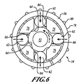
- FIGS. 4, 5 and 6 illustrate an exemplary progression of the radially expanding clutch assembly 50 changing between a drive condition in FIG. 4 and a clutch out or a reduced torque condition in FIG. 6 .
- the radially expanding clutch assembly 50 In the drive condition the radially expanding clutch assembly 50 is closed and can direct torque from the shaft member 52 to the gear member 54 with relatively little loss in torque.
- the radially expanding clutch assembly 50 In the clutch out or reduced torque condition, as illustrated in FIG. 6 , the radially expanding clutch assembly 50 is "open" and can direct torque at a reduced value (relative to the drive condition) from the shaft member 52 to the gear member 54.
- torque can be directed from the gear member 54 to the shaft member 52.
- the radially expanding clutch assembly 50 even in the clutch out or reduced torque condition ( FIG. 6 ), can direct some torque to the gear member 54 because the outer cylindrical surface 66 can still impart some torque on the rolling members 62.
- the rolling members 62 can reside within the longitudinal grooves 64 of the shaft member 52 and, as such, the radially expanding clutch assembly 50 is in the drive condition.
- torque can have an exemplary pathway from a surface 82 of the longitudinal grooves 64 via the rolling members 62 to a surface 84 of the lobes 76 that extend from the gear member 54.
- the rolling members 62 as illustrated in FIG. 5 , can move up the surface 82, out of the longitudinal grooves 64 and onto the outer cylindrical surfaces 66 of the shaft member 52, as shown in FIG. 6 .
- the rolling members 62 can move out of the longitudinal grooves 64 and can stretch (i.e., radially expand) the clutch spring 56 that can encircle (partially or wholly) the rolling members 62 and the lobes 76.
- the rolling members 62 can roll out of the longitudinal grooves 64 of the shaft member 52 and can be disposed between the clutch spring 56 and the outer cylindrical surfaces 66 of the shaft member 52.
- the radially expanding clutch assembly 50 as shown in FIG. 6 , can be in the clutch out or the reduced torque condition.
- the radially expanding clutch assembly 50 can contain various amounts of rolling members 62.
- the rolling members 62 can be configured as the pins 70, balls, other suitable rolling members 62 and/or one or more combinations thereof.
- four rolling members 62 can be implemented with the examples of the radially expanding clutch assembly 50.
- two rolling members 62 can be implemented with further examples of radially expanding clutch assembly 200.
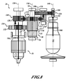
- an example of the transmission 24 for the right angle driver or drill 12 can establish a torque pathway 100 (illustrated with arrows) that can define a low speed condition of the transmission 24 in accordance with the present teachings.
- the motor 22 can connect to an output shaft member 102 having a gear portion 104.
- the gear portion 104 having gear teeth 106 can connect to a gear portion 108 having gear teeth 110 that is on an intermediate shaft member 112.
- the meshing of the gear portion 104 on the output shaft member 102 with the gear portion 108 on the intermediate shaft member 112 can define a first reduction mesh 114.
- the intermediate shaft member 112 can have a gear portion 116 having gear teeth 118 that can mesh with gear teeth 120 of a gear portion 122 that is on the shaft member 52.
- the meshing of the gear portion 108 on the intermediate shaft member 112 with the gear portion 122 on the shaft member 52 can form a second reduction mesh 124, i.e., two gear reductions.
- the intermediate shaft member 112 in some examples, can be omitted.
- the gear portion 104 that is on the output shaft member 102 can directly mesh with the gear portion 122 that is on the shaft member 52 but this would necessarily omit one of the reduction meshes mentioned above, i.e., a single gear reduction.
- Gear teeth 126 of the gear member 54 can mesh with the gear teeth 132 of a low speed gear portion 134 that is on the spindle shaft member 28.
- the gear teeth 120 of the gear portion 122 on the shaft member 52 can additionally mesh with gear teeth 128 of a high speed gear portion 130 that is on the spindle shaft member 28.
- the gear teeth 120, 128, however, can maintain a partial engagement with one another because the gear teeth 120, 128 of each of the respective gear portions 120, 130 do not completely line up, as illustrated in FIG. 7 .
- the high speed gear portion 130 in the low speed condition is not engaged to the spindle shaft member 28 (i.e., the high speed gear portion 130 is free to rotate around the spindle shaft member 28).
- the partial engagement can be shown to reduce the effort of moving the high speed gear portion 130 relative to the gear portion 122 on the shaft member 52.
- the low speed gear portion 134 and the high speed gear portion 130 on the spindle shaft member 28 can move in a longitudinal direction that is generally parallel to a longitudinal axis 136 of the spindle shaft member 28.
- the shaft member 52 can have a longitudinal axis 138 and the output shaft member 102 can have a longitudinal axis 140.
- the high speed gear portion 130 and the low speed gear portion 134 can move together between the high speed condition illustrated in FIG. 8 and the low speed condition illustrated in FIG. 7 .
- the low speed gear portion 134 can be engaged to the spindle shaft member 28 (i.e., not free to rotate around the spindle shaft member 28). In this arrangement, torque transmitted to the low speed gear portion 134 from the gear member 54 can drive the spindle shaft member 28 and ultimately the chuck assembly 26.
- the high speed gear portion 130 can be engaged to the spindle shaft member 28 (i.e., not free to rotate around the spindle shaft member 28).
- torque transmitted from the gear portion 104 of the output shaft member 102 to the gear portion 122 on the shaft member 52 is also directed to the high speed gear portion 130 on the spindle shaft member 28 and thus avoids the gear member 54.
- the radially expanding clutch assembly 50 in the above example, can therefore be bypassed in the high speed condition, as shown in FIG. 8 .
- the gear member 54 of the radially expanding clutch assembly 50 can drive the low speed gear portion 134 of the spindle shaft member 28 that is engaged to the spindle shaft member 28.
- the motor 22 can drive the spindle shaft member 28 via the low speed gear portion 134 of the spindle shaft member 28 and the gear member 54 of the radially expanding clutch assembly 50.
- the motor 22 can drive the spindle shaft member 28 via the high speed gear portion 130 that can be engaged to the spindle shaft member 28 and the gear portion 122 on the shaft member 52.
- the gear member 54 can provide little to no torque to the low speed gear portion 130.
- the transmission 24 can be switched between the high speed condition and the low speed condition and can provide a four to one gear ratio.
- the gear ratios established by the configuration of the gearing discussed throughout the disclosure can be configured in various aspects to, for example, produce different gear ratios to accommodate different requirements for the drill or driver 10.
- the torque threshold value can also be adjusted by varying the configuration of the surfaces 82, 84 of the longitudinal grooves 64 and/or the lobes 76, respectively, and/or adjusting the spring constant of the one or more clutch springs 56.
- spur and helical gears are illustrated, various gear teeth configurations (i.e., spur, helical, hypoid, bevel, etc.) can be used on various gears in the transmission 24, as applicable.
- the low speed gear portion 134 and the high speed gear portion 130 are separate gears that move relative to the spindle shaft member 28.
- the gears can engage and disengage to the spindle shaft member 28 by engaging with splines formed on the spindle shaft member 28 that can mesh with splines formed on the gears.
- the splines can be engaged and, in other longitudinal positions, the splines can be separated (i.e., axially disposed from one another) so that the gear can spin freely around the spindle shaft member 28.
- the splines, gear teeth, etc. can be formed with various suitable manufacturing processes, such as hobbing, index milling, grinding, etc.
- the gears, splines, etc. can be formed with powdered metal forming techniques.
- the transmission 24 can reduce rotational velocity and increase torque relative to an initial rotational velocity and initial torque provided by the motor 22.
- the radially expanding clutch assembly 50 can remain in the drive condition. In the drive condition, the shaft member 52 can drive the gear member 54 with relatively little loss in the value of the torque across the radially expanding clutch assembly 50.
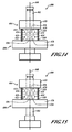
- the clutch spring 202 can be a unitary member (e.g., a sleeve) that can encircle (partially or wholly) the lobes 204 of a gear member 206 and/or rolling members 208. Similar to the radially expanding clutch assembly 50 ( FIG. 2 ) discussed above, as the value of torque surpasses the torque threshold value, the rolling members 208 can roll beyond planes 210.
- the planes 210 can be longitudinal grooves 212 that can be substantially flat, i.e., little or no curvature.
- the radially expanding clutch assembly 200 moves from a drive condition ( FIG. 9 ) to a clutch out (reduced torque) condition ( FIG. 11 ), as the shaft member 214 is no longer able to impart substantial torque to the gear member 206.
- the clutch spring 202 is shown in a generally circular shape 218 that can be indicative of the drive condition.
- the radially expanding clutch assembly 200 can deliver about the same amount of torque between the shaft member 214 and the gear member 206.
- the clutch spring 202 is shown in generally an elliptical shape 220, which is indicative of the clutch out or the reduced torque condition.
- torque delivered at the gear member 206 of the radially expanding clutch assembly 200 is reduced relative to the value of torque at the shaft member 214.
- the rolling members 208 can move onto the outer cylindrical surface 216 of the shaft member 214.
- the rolling members 208 can stretch (i.e., radially expand) the clutch spring 202 so as to form generally the elliptical shape 220 ( FIG. 11 ).
- the lobes 204 of the gear member 206 can have an arcuate outer surface 222.
- a shape of the arcuate outer surface 222 and the configuration of the clutch spring 202 in the drive condition can define a space 224 between the clutch spring 202 and the arcuate outer surface 222 of the lobe 204.
- the clutch spring 202 in the generally elliptical shape 220 can be stretched to a degree such that portions of the clutch spring 202 can reduce or eliminate the space 224 in the reduced torque condition.
- the clutch spring 202 can fully contact the arcuate outer surface 222 and in other examples the clutch spring 202 can approach the arcuate outer surface 222.
- the clutch spring 202 expands to take the generally taken the elliptical shape 220 and the radially expanding clutch assembly 200 is in the clutch out or reduced torque condition, the clutch spring 202 can additionally form spaces 226 between ends 228 of the lobes 204 and the clutch spring 202 adjacent to the rolling members 208.
- the ends 228 of the lobes 204 can be adjacent to surfaces 230 that can abut the rolling members 208.
- a radially expanding clutch assembly 300 can be similar to the radially expanding clutch assembly 50, as shown in FIG. 4 .
- the radially expanding clutch assembly 300 can have a clutch spring 302 that can encircle (partially or wholly) rolling members 304 and lobes 306 of a gear member 308.
- the rolling members 304 can be disposed in longitudinal grooves 310 formed in a shaft member 312.
- the clutch spring 302 can be a unitary member (e.g., a sleeve) and, as such, can continuously encircle the rolling members 304 and the lobes 306.
- a radially expanding spring clutch assembly 350 can be similar to the radially expanding clutch assembly 300, as shown in FIG. 12 .
- the radially expanding spring clutch assembly 350 can have a clutch spring 352 that can encircle (partially or wholly) rolling members 354 and lobes 356 of a gear member 358.
- the rolling members 354 can be disposed in longitudinal grooves 360 formed in a shaft member 362.
- the clutch spring 352 can be a coil spring or a power spring or also may be referred to as a spiral coiled spring.
- an outside end 364 of the clutch spring 352 can be revolved around an inside end 366 of the clutch spring 352 so as to tighten or loosen the clutch spring 352. Tightening of the clutch spring 352 can increase the torque threshold value associated with the spring clutch assembly 300. As illustrated in FIG. 13 , the outside end 364 can be revolved in a clockwise direction relative to the inside end 366 to increase a spring force exerted by the clutch spring 352. The outside end 364 can also be revolved in a counterclockwise direction relative to the inside end 366 to decrease the spring force exerted by the clutch spring 352 thus decreasing the torque threshold value.
- Portions of clutch spring 352 can be spaced at increasing radial distances from the shaft member 362, e.g., a spiral wound spring.
- the increasing radial distance can be along an arrow 368 that can be generally perpendicular to an outer cylindrical surface 370 of the shaft member 362.
- a transmission 400 includes a shaft member 402 on which a first gear assembly 404 and second gear assembly 406 can move generally about a longitudinal axis 408 of the shaft member 402.
- the first gear assembly 404 can include a first clutch spring 410 that holds a first set 412 of rolling members 414 between lobes 416 that can extend from a first output gear 418.
- a second gear assembly 406 can include a second clutch spring 420 that can hold a second set 422 of rolling members 424 between lobes 426 that extend from a second output gear 428.
- the first output gear 418 and the second output gear 428 can move longitudinally along the shaft member 402 to a position that can cause one or both of the output gears 418, 428 to engage for rotation with the shaft member 402.
- the shaft member 402 can include a continuous cylindrical surface portion 430 that can be longitudinally disposed next to a cylindrical outer surface portion 432 that can be interrupted by longitudinal grooves 434.
- the longitudinal grooves 434 can be formed at equally spaced radial positions along the shaft member 402.
- the first set 412 of rolling members 414 can be held within the longitudinal grooves 434 of the shaft member 402.
- a surface 436 of the longitudinal grooves 434 can transfer torque to a surface 438 of the lobes 416 of the first output gear via the rolling members 414.
- the first set 412 of rolling members 414 can be urged out of the longitudinal grooves 434 and migrate to the cylindrical outer surface portion 432 of the shaft member 402. Once the first set 412 of rolling members 414 advance along the surface 436 of the longitudinal grooves 434 to arrive at the cylindrical outer surface portion 432 of the shaft member 402.
- the transmission 400 can move from a drive condition to a reduced torque or clutch out condition.
- the surfaces 436 of the longitudinal grooves 434 can define a curvature 440 that can vary along longitudinal positions of the shaft member 402.
- the first gear assembly 404 and/or the second gear assembly 406 can engage the shaft member 402 at specific longitudinal positions of the shaft member 402.
- the curvature 440 of the longitudinal grooves 434 at the specific longitudinal positions can correlate with a known and predetermined torque threshold value. If a different torque threshold value is required, the first gear assembly 404 and/or the second gear assembly 406 can be moved along the shaft member 402 so that the rolling members 414, 424, as applicable, engage the longitudinal grooves 434 in a longitudinal position with a different curvature of the longitudinal groves 434 thus a different torque threshold value.
- the shaft member 402 can have at least three regions: a first region 450, a second region 452 and a third region 454.
- the first region 450 can define a continuous cylindrical outer surface 456 that can be at a nominal shaft diameter; nominal being relative to the diameter of the shaft member 402 in the second region 452.
- the second region 452 can define the continuous cylindrical surface portion 430.
- the third region 454 can define the cylindrical outer surface portion 432 that is interrupted by the longitudinal grooves 434.
- the first region 450 can define a continuous cylindrical outer surface 456 that can otherwise be interrupted by longitudinal grooves 435 that can be similar to (or different from) longitudinal grooves 434.
- the continuous cylindrical surface portion 430 that can have a reduced diameter relative to the continuous cylindrical surface portion 456 in the first region 450.
- the first gear assembly 404 can move longitudinally from having the rolling members 414 contained within the longitudinal grooves 434 (i.e., engaged to the shaft member 402) to a location on the shaft member 402 where the rolling members 414 contact the continuous cylindrical surface portion 430 having the reduced diameter. Because the continuous cylindrical surface portion 430 lacks any longitudinal grooves 434, the first gear assembly is free to rotate around the shaft member 402.
- the clutch spring 410 and the clutch spring 420 can each be a single unitary member and can encircle (partially or wholly) both the first and second set of rolling members 414, 424 on the first and second gear assembly 404, 406 thus encircling the lobes 416, 426 and rolling members 414, 424 in each of the gear assemblies 404, 406.
- separate clutch springs can be used with the first gear assembly 404 and a second gear assembly 406 respectively.
- the first clutch spring 410 can have a first spring constant and the second clutch spring 420 can have a second spring constant.
- the spring constants can be equal and in other examples, the spring constants can be different. It will be appreciated in light of the disclosure that the threshold torque value associated with one or more of the gear assemblies 414, 424 can be adjusted by altering the curvature of the longitudinal grooves, the angle of the surface of the lobes to which the rolling members connect, the spring constant of the respective clutch springs and/or one or more combinations thereof.
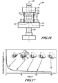
- FIG. 17 a relationship between a value of an angle 442 and the torque threshold value is shown.
- the angle 442 can be defined between the surface 438 of the lobes 416 in the first gear assembly 404 and the surface 436 of the longitudinal grooves 434 of the shaft member 402.
- the relationship between the value of the angle 442 and the torque threshold value is shown such that as the angle 442 decreases, the value of the torque threshold increases.
- the angle 442 can be defined between the surface 84 of the lobes 76 and the surface 82 of the longitudinal grooves 64, as shown in FIGS. 3 , 4 , 5 and 6 .
- the angle 442 can be defined between the plane 210 and the abutting end 230 of the lobes 204, as shown in FIGS. 9, 10 and 11 .
- an exemplary shaft member 500 is shown having at least three regions: a first region 502, a second region 504 and a third region 506.
- the first region 502 can include a continuous cylindrical surface portion 508.
- the second region 504 can include a cylindrical surface portion 510 interrupted by longitudinal grooves 512.
- the longitudinal grooves 512 can define planar portions 514, i.e., no curvature.
- Ramps 516 or other suitable contoured portions can provide one or more transitions between the regions 502, 504, 506.
- the third region 506 can include a cylindrical surface portion 518 interrupted by longitudinal grooves 520 having a curvature 522.
- the curvature 522 of the longitudinal grooves 520 can vary along a longitudinal axis 524 so as to have a first curvature 526 and a second curvature 528 at specific locations along the shaft member 500.
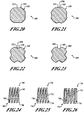
- a cross-section of the shaft member 500 is shown at a particular longitudinal location.
- the longitudinal grooves 512 are configured to have planar portions 514 that interrupt the cylindrical outer surface portions 510 of the shaft member 500.
- FIG. 21 another longitudinal location of the shaft member 500 is shown. In this longitudinal location, the outer cylindrical surface portion 518 is interrupted by longitudinal grooves 520 having the curvature 522 that can establish a first curvature configuration 526 that is associated with a predetermined torque threshold value.
- an additional longitudinal location is shown of the shaft member 500.
- the outer cylindrical portion 518 is interrupted by the longitudinal grooves 520 having the curvature 522 configured with a second curvature configuration 528 that is associated with another predetermined torque threshold value.
- the first gear assembly 404 and/or the second gear assembly 406 can be orientated along the shaft member 500 so that the respective rolling members 414, 416 can reside in the longitudinal grooves 520 at one or more of the above specific longitudinal locations.
- an alternative exemplary shaft member 600 can include an outer cylindrical surface portion 602 that is interrupted by the longitudinal grooves 604.
- the longitudinal grooves 604 can include a curvature 606.
- the curvature 606 can be configured in a V-shape. It will be appreciated in light of the disclosure that changing the configuration of the v-shape curvature can also adjust the torque threshold value.
- a clutch spring 700 can include helical coils 702 that can provide a helical spring 704 such that each of the helical coils 702 is spaced apart from each other. Ends 706 (one end or both ends) of the helical coils 702 can have a reduced cross-section (e.g., a ground end) so that when, for example, the clutch spring 700 is compressed axially, the ends 706 of the clutch spring 700 can provide a relatively more flat end of the clutch spring 700.
- a reduced cross-section e.g., a ground end
- the clutch spring 700 can define a substantially flat cross-section that can be maintained throughout the entire clutch spring 700 or portions thereof.
- the substantially flat cross-section can define a generally rectangular cross-section having two parallel sides that are substantially longer than the adjacent pair of parallel sides so as establish the substantially flat cross-section.
- intersections of the parallel sides i.e., corners
- a clutch spring 730 can include helical coils 732 that can provide a helical spring 734 such that each of the helical coils 732 is spaced apart from each other. Ends 736 (one end or both ends) of the helical coils 732 can be spaced from the immediately adjacent helical coil so as to establish an open condition, i.e., the ends 736 of the helical coils 732 do not touch other portions of the clutch spring 730.
- the clutch spring 730 can define a substantially flat cross-section that can be maintained throughout the entire clutch spring 730 or portions thereof.
- a clutch spring 750 can include helical coils 752 that can provide a helical spring 754 such that each of the helical coils 752 is spaced apart from each other.
- the ends 756 (one end or both ends) of the helical coils 752 are configured to contact the immediately adjacent helical coil so as to establish a closed end condition, i.e., the ends 756 of the helical coils 752 do touch (or are positioned relatively close to) other portions of the clutch spring 750.
- the clutch spring 750 can define a substantially flat cross-section that can be maintained throughout the entire clutch spring 750 or portions thereof.
- clutch springs 700, 730, 750 can implemented similar to clutch spring 56, 202, 302, 352, 410, 420 ( FIGS. 2 , 9 , 12, 13 and 14 ). It will also be appreciated in light of the disclosure that other suitable cross-sections of the clutch spring can used, such as, but not limited to, square and circular cross-sections. Furthermore, the radially expanding clutch spring can implemented in a cylindrical shape, a conical shape, other suitable shapes and one or more suitable combinations thereof.
Landscapes
- Engineering & Computer Science (AREA)
- General Engineering & Computer Science (AREA)
- Mechanical Engineering (AREA)
- One-Way And Automatic Clutches, And Combinations Of Different Clutches (AREA)
- Gear Transmission (AREA)
- Mechanical Operated Clutches (AREA)
- Structure Of Transmissions (AREA)
Priority Applications (2)
| Application Number | Priority Date | Filing Date | Title |
|---|---|---|---|
| EP10153081.4A EP2177787B1 (de) | 2007-09-11 | 2008-08-14 | Elektrisches Werkzeug |
| EP10153080A EP2184123B1 (de) | 2007-09-11 | 2008-08-14 | Getriebe und variable radial expandierende Federkupplungsanordnung |
Applications Claiming Priority (1)
| Application Number | Priority Date | Filing Date | Title |
|---|---|---|---|
| US11/853,435 US7793560B2 (en) | 2007-09-11 | 2007-09-11 | Transmission and variable radially expanding spring clutch assembly |
Related Child Applications (2)
| Application Number | Title | Priority Date | Filing Date |
|---|---|---|---|
| EP10153081.4 Division-Into | 2010-02-09 | ||
| EP10153080.6 Division-Into | 2010-02-09 |
Publications (3)
| Publication Number | Publication Date |
|---|---|
| EP2037152A2 true EP2037152A2 (de) | 2009-03-18 |
| EP2037152A3 EP2037152A3 (de) | 2009-05-20 |
| EP2037152B1 EP2037152B1 (de) | 2011-05-18 |
Family
ID=40430435
Family Applications (3)
| Application Number | Title | Priority Date | Filing Date |
|---|---|---|---|
| EP10153080A Not-in-force EP2184123B1 (de) | 2007-09-11 | 2008-08-14 | Getriebe und variable radial expandierende Federkupplungsanordnung |
| EP08162397A Ceased EP2037152B1 (de) | 2007-09-11 | 2008-08-14 | Getriebe und variable radial expandierende Federkupplungsanordnung |
| EP10153081.4A Not-in-force EP2177787B1 (de) | 2007-09-11 | 2008-08-14 | Elektrisches Werkzeug |
Family Applications Before (1)
| Application Number | Title | Priority Date | Filing Date |
|---|---|---|---|
| EP10153080A Not-in-force EP2184123B1 (de) | 2007-09-11 | 2008-08-14 | Getriebe und variable radial expandierende Federkupplungsanordnung |
Family Applications After (1)
| Application Number | Title | Priority Date | Filing Date |
|---|---|---|---|
| EP10153081.4A Not-in-force EP2177787B1 (de) | 2007-09-11 | 2008-08-14 | Elektrisches Werkzeug |
Country Status (4)
| Country | Link |
|---|---|
| US (4) | US7793560B2 (de) |
| EP (3) | EP2184123B1 (de) |
| CN (1) | CN201382102Y (de) |
| AT (1) | ATE531471T1 (de) |
Cited By (1)
| Publication number | Priority date | Publication date | Assignee | Title |
|---|---|---|---|---|
| CN110548890A (zh) * | 2018-06-04 | 2019-12-10 | 鸿鼎科技有限公司 | 三孔钻夹头成型装置及成型方法 |
Families Citing this family (23)
| Publication number | Priority date | Publication date | Assignee | Title |
|---|---|---|---|---|
| AT503139B1 (de) * | 2006-02-08 | 2009-02-15 | Blum Gmbh Julius | Ausstosser mit rutschkupplung |
| DE102007014756A1 (de) * | 2007-03-28 | 2008-10-02 | Robert Bosch Gmbh | Handwerkzeug |
| US8074858B2 (en) * | 2008-07-17 | 2011-12-13 | Tyco Healthcare Group Lp | Surgical retraction mechanism |
| US8540580B2 (en) | 2009-08-12 | 2013-09-24 | Black & Decker Inc. | Tool bit or tool holder for power tool |
| JP5637779B2 (ja) * | 2010-08-26 | 2014-12-10 | トックベアリング株式会社 | トルクリミッタ |
| CN201881326U (zh) * | 2010-11-09 | 2011-06-29 | 徐雪峰 | 一种电动工具用冲击机构 |
| US8820433B2 (en) | 2011-08-30 | 2014-09-02 | Black & Decker Inc. | Axially compact power tool |
| JP6033622B2 (ja) * | 2011-09-27 | 2016-11-30 | ナブテスコ株式会社 | 風車用駆動装置 |
| US9140333B2 (en) * | 2012-01-23 | 2015-09-22 | Merit Engineering & Equipment Company | Saw gear box |
| CN102649266B (zh) * | 2012-04-16 | 2015-04-08 | 制尚电器(浙江)有限公司 | 一种多功能双速电锤 |
| EP2777883A1 (de) | 2013-03-13 | 2014-09-17 | Black & Decker Inc. | Nuss-Haltevorrichtung |
| US9289878B2 (en) | 2013-08-30 | 2016-03-22 | Ingersoll-Rand Company | Grinders with friction drives |
| CN106286639B (zh) * | 2016-08-09 | 2018-10-02 | 沈阳东软医疗系统有限公司 | 扭矩限制器及具有该扭矩限制器的悬吊系统 |
| EP3535095B1 (de) | 2016-11-04 | 2023-12-06 | Milwaukee Electric Tool Corporation | Kupplungsmechanismus für ein rotierendes elektrowerkzeug |
| JP2018173135A (ja) * | 2017-03-31 | 2018-11-08 | 株式会社ジェイテクト | クラッチ、およびそれを備えたアクチュエータ |
| US10808805B2 (en) * | 2018-04-05 | 2020-10-20 | Minchuen Electrical Machinery Co., Ltd. | Drilling machine and transmission structure thereof |
| CN110666217B (zh) * | 2019-10-17 | 2020-10-30 | 南通东科工具有限公司 | 一种可自动改变扭矩的钻枪 |
| CN112628375B (zh) * | 2020-12-16 | 2022-03-01 | 西南大学 | 三轮车中央驱动自适应变速总成 |
| CN112682480B (zh) * | 2021-01-15 | 2021-09-14 | 天津大学 | 一种齿轮传动结构 |
| CN112720005A (zh) * | 2021-02-06 | 2021-04-30 | 浙江铂动工贸有限公司 | 一种高精度钻铣装置 |
| DE202021102825U1 (de) | 2021-05-25 | 2022-08-30 | Rollax Gmbh & Co. Kg | Überlastschutzkupplung |
| CN114922917B (zh) * | 2022-05-30 | 2025-05-27 | 宁波岚骐智能科技有限公司 | 一种离合执行器 |
| CN115681493A (zh) * | 2022-12-05 | 2023-02-03 | 浙江东森电器有限公司 | 一种电动工具的机械变速结构 |
Citations (1)
| Publication number | Priority date | Publication date | Assignee | Title |
|---|---|---|---|---|
| EP0608083A1 (de) | 1993-01-19 | 1994-07-27 | Black & Decker Inc. | Motorisch angetriebenes Werkzeug, insbesondere ein Elektrowerkzeug |
Family Cites Families (112)
| Publication number | Priority date | Publication date | Assignee | Title |
|---|---|---|---|---|
| US1325464A (en) * | 1919-12-16 | Saeety-ratchet | ||
| US1398763A (en) * | 1921-11-29 | bearens | ||
| GB133153A (de) * | ||||
| US263709A (en) * | 1882-09-05 | Hubbard | ||
| US644150A (en) * | 1899-05-31 | 1900-02-27 | Henry C Smith | Window-frame. |
| US1651822A (en) * | 1926-02-09 | 1927-12-06 | Hobart Mfg Co | Transmission mechanism |
| US1812445A (en) * | 1927-08-27 | 1931-06-30 | Fred W Mayer | Torque controlled gear changing mechanism |
| US1795135A (en) * | 1929-03-04 | 1931-03-03 | Zahnradfabrik Ag | Gear |
| US1805692A (en) * | 1929-10-22 | 1931-05-19 | American Mach & Foundry | Automatic slip coupling |
| US1810450A (en) * | 1929-11-28 | 1931-06-16 | Broembsen Maxwell Louis Fr Von | Variable speed-gear mechanism |
| US2246996A (en) * | 1938-10-27 | 1941-06-24 | Konstruktion Und Verwertung Au | Change-speed gearing |
| US2263709A (en) * | 1939-12-11 | 1941-11-25 | Cleveland Pneumatic Tool Co | Clutch device |
| US2344673A (en) * | 1942-02-16 | 1944-03-21 | Lowell H Brown | Safety roller coupling |
| US2514569A (en) * | 1944-09-01 | 1950-07-11 | Enquist Gosta Thure Harry | Releasable coupling device |
| US2668426A (en) * | 1948-10-01 | 1954-02-09 | Vaino A Hoover | Torque limiting clutch |
| US2631696A (en) * | 1949-05-02 | 1953-03-17 | Boeing Co | Brake control mechanism |
| US2692486A (en) * | 1952-08-19 | 1954-10-26 | Underwood Corp | Rotary drive coupling |
| US2668428A (en) * | 1952-10-02 | 1954-02-09 | Marvel Specialty | Device for restoring defective knitted fabrics |
| DE1712948U (de) | 1955-03-24 | 1955-12-15 | Jean Walterscheid Fa | Wellenkupplung mit drehmomentbegrenzung. |
| US2860498A (en) * | 1955-04-04 | 1958-11-18 | North American Aviation Inc | Ball action slip clutch |
| DE1725799U (de) | 1956-04-21 | 1956-07-05 | Moenus Maschf | Schraubentreiber fuer schraubmaschinen. |
| US2854831A (en) * | 1956-09-11 | 1958-10-07 | Milwaukee Electric Tool Corp | Torque adjustment for power driven tools |
| US2882704A (en) * | 1957-06-18 | 1959-04-21 | Robert C Quackenbush | Clutch with overload release |
| US3005325A (en) * | 1958-09-08 | 1961-10-24 | Reed Roller Bit Co | Clutch mechanism |
| US2957323A (en) * | 1958-09-17 | 1960-10-25 | Reed Roller Bit Co | Rolling impulse clutch |
| US3205965A (en) | 1961-08-04 | 1965-09-14 | Linde Eismasch Ag | Motor vehicle |
| US3205985A (en) * | 1963-03-18 | 1965-09-14 | Gardner Denver Co | Torque responsive clutch |
| FR93592E (fr) * | 1967-04-19 | 1969-04-18 | Marcel Alexis | Dispositif mécanique de limitation de couple conjugué avec un débrayage. |
| DE2134506C3 (de) | 1967-04-19 | 1974-11-28 | Marcel Pierre Alexis Paris Bouhot | Kupplung mit drehmomentabhängiger Stillsetzung |
| US3667575A (en) * | 1967-04-19 | 1972-06-06 | Marcel Pierre Alexis Bouhot | Double acting free wheel |
| US3631945A (en) * | 1969-06-09 | 1972-01-04 | Olivetti & Co Spa | Speed-changing device for a rotary member |
| DE1948055A1 (de) * | 1969-09-23 | 1971-04-01 | Impex Essen Vertrieb | Elektrisch betriebener Bohrhammer |
| US3616883A (en) * | 1970-06-08 | 1971-11-02 | Black & Decker Mfg Co | Adjustable clutch |
| US3804222A (en) * | 1972-03-16 | 1974-04-16 | Us Navy | Clutch with centrifugal engaging and releasing weights |
| US3877253A (en) * | 1972-12-01 | 1975-04-15 | Skuttle Mfg Co | Slip clutch assembly for torque limiting drive for humidifier rotors and the like |
| DE2335184C3 (de) | 1973-07-11 | 1980-07-17 | Dieter Haubold Industrielle Nagelgeraete, 3005 Hemmingen-Westerfeld | Schutzvorrichtung gegen Überlastung eines maschinell angetriebenen Werkzeugvorsatzes |
| DE7403870U (de) | 1973-12-14 | 1974-05-30 | Irvator Ab | Momentenwerkzeug, besonders Momentenaufsteckschlüssel |
| SE377900B (de) * | 1974-01-15 | 1975-08-04 | Atlas Copco Ab | |
| US3991590A (en) * | 1974-05-06 | 1976-11-16 | F. Jos. Lamb Company | Safety overload clutch |
| DE2427352A1 (de) | 1974-06-06 | 1975-12-18 | Ulrich Schmidt | Vorsatzschraubendreher |
| DE2511469C2 (de) | 1975-03-15 | 1985-06-27 | Robert Bosch Gmbh, 7000 Stuttgart | Elektrowerkzeug - insbesondere Handbohrmaschine - mit einem Zweiganggetriebe |
| DE2709946C2 (de) * | 1977-03-08 | 1982-12-23 | Novopress GmbH Pressen und Presswerkzeuge & Co KG, 4000 Düsseldorf | Tragbares Handwerkzeug |
| US4238978A (en) * | 1979-03-16 | 1980-12-16 | Lowell Corporation | Torque wrench |
| US4253554A (en) * | 1979-07-16 | 1981-03-03 | Nisenson Technology Corp. | Bi-directional clutch |
| US4362161A (en) * | 1980-10-27 | 1982-12-07 | Codman & Shurtleff, Inc. | Cranial drill |
| DE3104626A1 (de) | 1981-02-10 | 1982-09-23 | Kernforschungszentrum Karlsruhe Gmbh, 7500 Karlsruhe | "fernbedienbarer schraubendreher" |
| US4619567A (en) * | 1984-05-11 | 1986-10-28 | Campbell James H | Bit holder with impact release mechanism |
| DE3437083C2 (de) * | 1984-10-05 | 1986-08-14 | Horst-Günter 1000 Berlin Rißmann | Werkzeug, insbesondere Schraubenwerkzeug mit begrenzt übertragbarem Drehmoment |
| DE3443072A1 (de) | 1984-11-26 | 1986-05-28 | Rudolf Dipl.-Ing. Höpfner (FH), 8500 Nürnberg | Drehmomentbegrenzer |
| DE8607168U1 (de) | 1986-03-15 | 1987-07-23 | Robert Bosch Gmbh, 7000 Stuttgart | Zusatzhandgriff für eine Handwerkzeugmaschine |
| US4830001A (en) * | 1987-08-10 | 1989-05-16 | Codman & Shurtleff, Inc. | Assembly sleeve for cranial drill |
| DE3807308A1 (de) | 1988-03-05 | 1989-09-14 | Licentia Gmbh | Sicherheitsrutschkupplung eines elektrowerkzeuges mit radialer wirkungsweise |
| US4901610A (en) * | 1988-07-07 | 1990-02-20 | Precision Instruments, Inc. | Adjustable torque controlling mechanism |
| US4986369A (en) * | 1988-07-11 | 1991-01-22 | Makita Electric Works, Ltd. | Torque adjusting mechanism for power driven rotary tools |
| JPH0798311B2 (ja) * | 1988-10-12 | 1995-10-25 | 富士写真フイルム株式会社 | ねじ締め装置 |
| JPH04141332A (ja) | 1990-09-28 | 1992-05-14 | Fujitsu Ltd | 螺子締め装置 |
| US5123313A (en) * | 1990-12-21 | 1992-06-23 | Ab Momento | Torsion socket |
| SE9100070L (sv) * | 1991-01-10 | 1992-04-27 | Atlas Copco Tools Ab | Kraftskruvdragare |
| DE4143678B4 (de) | 1991-02-27 | 2005-03-10 | Holland Letz Felo Werkzeug | Halter für Schraubendreher-Einsätze |
| DE4143218C3 (de) | 1991-02-27 | 2003-03-20 | Holland Letz Felo Werkzeug | Vorrichtung zur Verbindung von Schraubendreher-Einsätzen |
| DE4243608C2 (de) * | 1992-12-22 | 2000-10-19 | Werner Hermann Wera Werke | Werkzeug |
| DE4300083A1 (de) | 1993-01-06 | 1994-07-07 | Masch Und Werkzeugbau Gmbh | Überlastkupplung |
| US5346023A (en) * | 1993-02-11 | 1994-09-13 | Hitachi Koki Company Limited | Slipping torque changing apparatus for impact tool |
| US5309799A (en) * | 1993-08-05 | 1994-05-10 | Jore Matthew B | Transparent-sleeve screw holding and driving tool |
| DE4341378A1 (de) * | 1993-12-04 | 1995-06-08 | Fischer Artur Werke Gmbh | Bohrvorrichtung mit radial auslenkbarer Bohrspindel |
| DE4344849A1 (de) * | 1993-12-29 | 1995-07-06 | Fein C & E | Werkzeugmaschine |
| SE501811C2 (sv) * | 1994-03-31 | 1995-05-22 | Gustav Rennerfelt | Momentnyckel |
| US5577426A (en) * | 1994-11-08 | 1996-11-26 | Snap-On Technologies, Inc. | Magnetic bit holder and hand tool incorporating same |
| US6321855B1 (en) * | 1994-12-29 | 2001-11-27 | George Edward Barnes | Anti-vibration adaptor |
| US6123157A (en) * | 1994-12-29 | 2000-09-26 | Ergonomics Specialties | Anti-vibration adaptor |
| JP2910599B2 (ja) * | 1995-01-26 | 1999-06-23 | ノーリツ鋼機株式会社 | トルク制御装置 |
| KR100212857B1 (ko) * | 1996-01-24 | 1999-08-02 | 윤종용 | 고주파가열장치 |
| SE9600934D0 (sv) * | 1996-03-11 | 1996-03-11 | Atlas Copco Tools Ab | Power nutrunner with torque release xclutch |
| SE9600933D0 (sv) * | 1996-03-11 | 1996-03-11 | Atlas Copco Tools Ab | Power nutrunner |
| US5746298A (en) * | 1996-07-19 | 1998-05-05 | Snap-On Technologies, Inc. | Adjustable torque-limiting mini screwdriver |
| DE19722798C2 (de) | 1997-05-30 | 2002-11-14 | Feinmechanik Gmbh | Kupplung |
| AU8020098A (en) | 1997-06-02 | 1998-12-21 | Wera Werk Hermann Werner Gmbh & Co. | Clamping chuck for bits or the like |
| US5862705A (en) * | 1997-08-13 | 1999-01-26 | Lee; Chi-Nan | Speed transferring system for a lathe |
| US6053675A (en) * | 1998-06-26 | 2000-04-25 | Black & Decker Inc. | Quick-acting tool bit holder |
| DE19901662B4 (de) * | 1999-01-18 | 2013-10-10 | Wera-Werk Hermann Werner Gmbh & Co. Kg | Spannfutter für Bits oder dergleichen |
| US6536536B1 (en) * | 1999-04-29 | 2003-03-25 | Stephen F. Gass | Power tools |
| US7150680B2 (en) * | 1999-05-14 | 2006-12-19 | Precimed S.A. | Drive shaft coupling |
| SE513457C2 (sv) * | 1999-10-11 | 2000-09-18 | Kapman Ab | Momentbegränsad skruvmejsel |
| US6568693B2 (en) * | 2000-05-24 | 2003-05-27 | Black & Decker Inc. | Ratcheting hand held tool |
| DE10026205A1 (de) * | 2000-05-26 | 2001-11-29 | Adolf Wuerth Gmbh & Co Kg | Vorrichtung zum Verbinden eines Werkzeugs mit einem Antrieb |
| WO2002000396A1 (de) * | 2000-06-27 | 2002-01-03 | Wera Werk Hermann Werner Gmbh & Co. Kg | Schraubwerkzeug und verfahren zur herstellung eines schraubwerkzeuges |
| DE10037808A1 (de) * | 2000-08-03 | 2002-02-14 | Bosch Gmbh Robert | Handwerkzeugmaschine |
| US6702090B2 (en) * | 2001-03-14 | 2004-03-09 | Milwaukee Electric Tool Corporation | Power tool and spindle lock system |
| JP2002337062A (ja) * | 2001-03-14 | 2002-11-26 | Daijiro Nakamura | 回転出力装置 |
| AUPR389601A0 (en) * | 2001-03-22 | 2001-04-12 | Abw Australia Pty. Ltd. | A driver bit holder |
| DE10122272A1 (de) | 2001-05-08 | 2002-11-14 | Bosch Gmbh Robert | Überlastkupplung zur Übertragung eines in der Höhe begrenzten Drehmoments |
| SE520640C2 (sv) * | 2001-10-16 | 2003-08-05 | Atlas Copco Tools Ab | Handhållet kraftverktyg med en roterande utgående axel |
| US7063201B2 (en) * | 2001-11-27 | 2006-06-20 | Milwaukee Electric Tool Corporation | Power tool and spindle lock system |
| US6644150B2 (en) * | 2002-01-25 | 2003-11-11 | Tsai-Ching Chen | Tool bit holding device with an improved retaining effect |
| CA98829S (en) * | 2002-03-04 | 2004-08-31 | Maxtech Mfg Inc | Screw guide |
| JP4295970B2 (ja) | 2002-10-23 | 2009-07-15 | 株式会社東芝 | リバースイオントフォレシス装置及びリバースイオントフォレシス測定方法 |
| USD488695S1 (en) * | 2003-02-25 | 2004-04-20 | Malco Products, Inc. | Drill shear attachment |
| US6796921B1 (en) * | 2003-05-30 | 2004-09-28 | One World Technologies Limited | Three speed rotary power tool |
| EP1491294B1 (de) * | 2003-06-20 | 2006-10-18 | Zimmer GmbH | Eindrehwerkzeug für Implantatschrauben |
| AU2004257893C1 (en) * | 2003-07-22 | 2010-07-22 | Nt Consulting International Pty Limited | Single clutch transmission |
| DE10341697B3 (de) * | 2003-09-10 | 2004-10-07 | Felo-Werkzeugfabrik Holland-Letz Gmbh | Schraubwerkzeug mit einer Vorrichtung zur Begrenzung des übertragenen Drehmomentes |
| US6974011B2 (en) * | 2003-12-22 | 2005-12-13 | The Timken Company | Directional clutch |
| US20060016283A1 (en) * | 2004-07-20 | 2006-01-26 | Junji Owa | Torque limiter, and garbage dewatering apparatus using the same |
| US7318691B2 (en) * | 2004-09-10 | 2008-01-15 | Engineered Spring Products, Inc. | Tool apparatus for milling machine |
| US7677844B2 (en) * | 2005-04-19 | 2010-03-16 | Black & Decker Inc. | Electronic clutch for tool chuck with power take off and dead spindle features |
| JP2006315093A (ja) * | 2005-05-10 | 2006-11-24 | Hitachi Koki Co Ltd | インパクト工具 |
| DE102005057368B4 (de) | 2005-12-01 | 2007-12-20 | Deudiam Diamantwerkzeuge Und Maschinen Gmbh | In eine handführbare Bohrmaschine einsetzbare Kupplung |
| TWI281988B (en) * | 2005-12-16 | 2007-06-01 | Chung Shan Inst Of Science | Module and method for estimating signal direction of arrival |
| JP2007190666A (ja) | 2005-12-22 | 2007-08-02 | Kts:Kk | トルク伝達工具 |
| DE102006012385B3 (de) | 2006-03-15 | 2007-10-11 | Iav Gmbh Ingenieurgesellschaft Auto Und Verkehr | Ventiltriebsanordnung für eine Brennkraftmaschine |
| USD589319S1 (en) * | 2007-02-08 | 2009-03-31 | Black & Decker Inc. | Pivoting bit holder |
| JP5073321B2 (ja) * | 2007-03-07 | 2012-11-14 | 株式会社マキタ | 回転工具のビット取り付け装置 |
-
2007
- 2007-09-11 US US11/853,435 patent/US7793560B2/en active Active
-
2008
- 2008-08-14 EP EP10153080A patent/EP2184123B1/de not_active Not-in-force
- 2008-08-14 AT AT10153080T patent/ATE531471T1/de active
- 2008-08-14 EP EP08162397A patent/EP2037152B1/de not_active Ceased
- 2008-08-14 EP EP10153081.4A patent/EP2177787B1/de not_active Not-in-force
- 2008-09-11 CN CN200820131526.3U patent/CN201382102Y/zh not_active Expired - Fee Related
-
2010
- 2010-07-20 US US12/840,098 patent/US8347750B2/en active Active
- 2010-07-20 US US12/840,127 patent/US8984977B2/en active Active
- 2010-07-29 US US12/846,421 patent/US20100319474A1/en not_active Abandoned
Patent Citations (1)
| Publication number | Priority date | Publication date | Assignee | Title |
|---|---|---|---|---|
| EP0608083A1 (de) | 1993-01-19 | 1994-07-27 | Black & Decker Inc. | Motorisch angetriebenes Werkzeug, insbesondere ein Elektrowerkzeug |
Cited By (1)
| Publication number | Priority date | Publication date | Assignee | Title |
|---|---|---|---|---|
| CN110548890A (zh) * | 2018-06-04 | 2019-12-10 | 鸿鼎科技有限公司 | 三孔钻夹头成型装置及成型方法 |
Also Published As
| Publication number | Publication date |
|---|---|
| US8984977B2 (en) | 2015-03-24 |
| EP2037152A3 (de) | 2009-05-20 |
| ATE531471T1 (de) | 2011-11-15 |
| EP2037152B1 (de) | 2011-05-18 |
| CN201382102Y (zh) | 2010-01-13 |
| EP2184123B1 (de) | 2011-11-02 |
| US20100319474A1 (en) | 2010-12-23 |
| US7793560B2 (en) | 2010-09-14 |
| EP2177787B1 (de) | 2013-05-08 |
| EP2177787A1 (de) | 2010-04-21 |
| US20100276244A1 (en) | 2010-11-04 |
| US20090064810A1 (en) | 2009-03-12 |
| US8347750B2 (en) | 2013-01-08 |
| US20100300226A1 (en) | 2010-12-02 |
| EP2184123A1 (de) | 2010-05-12 |
Similar Documents
| Publication | Publication Date | Title |
|---|---|---|
| US7793560B2 (en) | Transmission and variable radially expanding spring clutch assembly | |
| EP2644326B1 (de) | Gehäuse und Getriebe für einen Bohrer oder Schrauber | |
| US8887831B2 (en) | Transmission for power tool with variable speed ratio | |
| US9494200B2 (en) | Clutch for power tool | |
| EP2875906B1 (de) | Mehrgängiges Zykloidengetriebe | |
| US8251156B2 (en) | Compliant shifting mechanism for right angle drill | |
| EP2614931A1 (de) | Angetriebenes Werkzeug mit Drehmomentkupplung | |
| EP4212281A1 (de) | Mutterkanalzubehör für elektrowerkzeug |
Legal Events
| Date | Code | Title | Description |
|---|---|---|---|
| PUAI | Public reference made under article 153(3) epc to a published international application that has entered the european phase |
Free format text: ORIGINAL CODE: 0009012 |
|
| AK | Designated contracting states |
Kind code of ref document: A2 Designated state(s): AT BE BG CH CY CZ DE DK EE ES FI FR GB GR HR HU IE IS IT LI LT LU LV MC MT NL NO PL PT RO SE SI SK TR |
|
| AX | Request for extension of the european patent |
Extension state: AL BA MK RS |
|
| PUAL | Search report despatched |
Free format text: ORIGINAL CODE: 0009013 |
|
| AK | Designated contracting states |
Kind code of ref document: A3 Designated state(s): AT BE BG CH CY CZ DE DK EE ES FI FR GB GR HR HU IE IS IT LI LT LU LV MC MT NL NO PL PT RO SE SI SK TR |
|
| AX | Request for extension of the european patent |
Extension state: AL BA MK RS |
|
| 17P | Request for examination filed |
Effective date: 20090616 |
|
| 17Q | First examination report despatched |
Effective date: 20090709 |
|
| AKX | Designation fees paid |
Designated state(s): DE GB IT |
|
| GRAP | Despatch of communication of intention to grant a patent |
Free format text: ORIGINAL CODE: EPIDOSNIGR1 |
|
| GRAS | Grant fee paid |
Free format text: ORIGINAL CODE: EPIDOSNIGR3 |
|
| GRAA | (expected) grant |
Free format text: ORIGINAL CODE: 0009210 |
|
| REG | Reference to a national code |
Ref country code: GB Ref legal event code: FG4D |
|
| REG | Reference to a national code |
Ref country code: DE Ref legal event code: R096 Ref document number: 602008006967 Country of ref document: DE Effective date: 20110630 |
|
| PLBE | No opposition filed within time limit |
Free format text: ORIGINAL CODE: 0009261 |
|
| STAA | Information on the status of an ep patent application or granted ep patent |
Free format text: STATUS: NO OPPOSITION FILED WITHIN TIME LIMIT |
|
| 26N | No opposition filed |
Effective date: 20120221 |
|
| REG | Reference to a national code |
Ref country code: DE Ref legal event code: R097 Ref document number: 602008006967 Country of ref document: DE Effective date: 20120221 |
|
| PGFP | Annual fee paid to national office [announced via postgrant information from national office to epo] |
Ref country code: LU Payment date: 20180925 Year of fee payment: 17 |
|
| PG25 | Lapsed in a contracting state [announced via postgrant information from national office to epo] |
Ref country code: IT Free format text: LAPSE BECAUSE OF NON-PAYMENT OF DUE FEES Effective date: 20190814 |
|
| PGFP | Annual fee paid to national office [announced via postgrant information from national office to epo] |
Ref country code: GB Payment date: 20210707 Year of fee payment: 14 Ref country code: DE Payment date: 20210706 Year of fee payment: 14 |
|
| REG | Reference to a national code |
Ref country code: DE Ref legal event code: R119 Ref document number: 602008006967 Country of ref document: DE |
|
| GBPC | Gb: european patent ceased through non-payment of renewal fee |
Effective date: 20220814 |
|
| PG25 | Lapsed in a contracting state [announced via postgrant information from national office to epo] |
Ref country code: DE Free format text: LAPSE BECAUSE OF NON-PAYMENT OF DUE FEES Effective date: 20230301 |
|
| PG25 | Lapsed in a contracting state [announced via postgrant information from national office to epo] |
Ref country code: GB Free format text: LAPSE BECAUSE OF NON-PAYMENT OF DUE FEES Effective date: 20220814 |