EP2037098A2 - Turbocompound-Brennkraftmaschine - Google Patents
Turbocompound-Brennkraftmaschine Download PDFInfo
- Publication number
- EP2037098A2 EP2037098A2 EP20080021613 EP08021613A EP2037098A2 EP 2037098 A2 EP2037098 A2 EP 2037098A2 EP 20080021613 EP20080021613 EP 20080021613 EP 08021613 A EP08021613 A EP 08021613A EP 2037098 A2 EP2037098 A2 EP 2037098A2
- Authority
- EP
- European Patent Office
- Prior art keywords
- internal combustion
- combustion engine
- pressure
- pressure turbine
- exhaust gas
- Prior art date
- Legal status (The legal status is an assumption and is not a legal conclusion. Google has not performed a legal analysis and makes no representation as to the accuracy of the status listed.)
- Granted
Links
Images

Classifications
-
- F—MECHANICAL ENGINEERING; LIGHTING; HEATING; WEAPONS; BLASTING
- F02—COMBUSTION ENGINES; HOT-GAS OR COMBUSTION-PRODUCT ENGINE PLANTS
- F02D—CONTROLLING COMBUSTION ENGINES
- F02D9/00—Controlling engines by throttling air or fuel-and-air induction conduits or exhaust conduits
- F02D9/04—Controlling engines by throttling air or fuel-and-air induction conduits or exhaust conduits concerning exhaust conduits
- F02D9/06—Exhaust brakes
-
- F—MECHANICAL ENGINEERING; LIGHTING; HEATING; WEAPONS; BLASTING
- F02—COMBUSTION ENGINES; HOT-GAS OR COMBUSTION-PRODUCT ENGINE PLANTS
- F02B—INTERNAL-COMBUSTION PISTON ENGINES; COMBUSTION ENGINES IN GENERAL
- F02B37/00—Engines characterised by provision of pumps driven at least for part of the time by exhaust
- F02B37/004—Engines characterised by provision of pumps driven at least for part of the time by exhaust with exhaust drives arranged in series
-
- F—MECHANICAL ENGINEERING; LIGHTING; HEATING; WEAPONS; BLASTING
- F02—COMBUSTION ENGINES; HOT-GAS OR COMBUSTION-PRODUCT ENGINE PLANTS
- F02B—INTERNAL-COMBUSTION PISTON ENGINES; COMBUSTION ENGINES IN GENERAL
- F02B37/00—Engines characterised by provision of pumps driven at least for part of the time by exhaust
- F02B37/013—Engines characterised by provision of pumps driven at least for part of the time by exhaust with exhaust-driven pumps arranged in series
-
- F—MECHANICAL ENGINEERING; LIGHTING; HEATING; WEAPONS; BLASTING
- F02—COMBUSTION ENGINES; HOT-GAS OR COMBUSTION-PRODUCT ENGINE PLANTS
- F02B—INTERNAL-COMBUSTION PISTON ENGINES; COMBUSTION ENGINES IN GENERAL
- F02B37/00—Engines characterised by provision of pumps driven at least for part of the time by exhaust
- F02B37/02—Gas passages between engine outlet and pump drive, e.g. reservoirs
- F02B37/025—Multiple scrolls or multiple gas passages guiding the gas to the pump drive
-
- F—MECHANICAL ENGINEERING; LIGHTING; HEATING; WEAPONS; BLASTING
- F02—COMBUSTION ENGINES; HOT-GAS OR COMBUSTION-PRODUCT ENGINE PLANTS
- F02B—INTERNAL-COMBUSTION PISTON ENGINES; COMBUSTION ENGINES IN GENERAL
- F02B37/00—Engines characterised by provision of pumps driven at least for part of the time by exhaust
- F02B37/12—Control of the pumps
-
- F—MECHANICAL ENGINEERING; LIGHTING; HEATING; WEAPONS; BLASTING
- F02—COMBUSTION ENGINES; HOT-GAS OR COMBUSTION-PRODUCT ENGINE PLANTS
- F02B—INTERNAL-COMBUSTION PISTON ENGINES; COMBUSTION ENGINES IN GENERAL
- F02B37/00—Engines characterised by provision of pumps driven at least for part of the time by exhaust
- F02B37/12—Control of the pumps
- F02B37/22—Control of the pumps by varying cross-section of exhaust passages or air passages, e.g. by throttling turbine inlets or outlets or by varying effective number of guide conduits
-
- F—MECHANICAL ENGINEERING; LIGHTING; HEATING; WEAPONS; BLASTING
- F02—COMBUSTION ENGINES; HOT-GAS OR COMBUSTION-PRODUCT ENGINE PLANTS
- F02B—INTERNAL-COMBUSTION PISTON ENGINES; COMBUSTION ENGINES IN GENERAL
- F02B41/00—Engines characterised by special means for improving conversion of heat or pressure energy into mechanical power
- F02B41/02—Engines with prolonged expansion
- F02B41/10—Engines with prolonged expansion in exhaust turbines
-
- F—MECHANICAL ENGINEERING; LIGHTING; HEATING; WEAPONS; BLASTING
- F02—COMBUSTION ENGINES; HOT-GAS OR COMBUSTION-PRODUCT ENGINE PLANTS
- F02D—CONTROLLING COMBUSTION ENGINES
- F02D9/00—Controlling engines by throttling air or fuel-and-air induction conduits or exhaust conduits
- F02D9/08—Throttle valves specially adapted therefor; Arrangements of such valves in conduits
- F02D9/12—Throttle valves specially adapted therefor; Arrangements of such valves in conduits having slidably-mounted valve members; having valve members movable longitudinally of conduit
-
- F—MECHANICAL ENGINEERING; LIGHTING; HEATING; WEAPONS; BLASTING
- F02—COMBUSTION ENGINES; HOT-GAS OR COMBUSTION-PRODUCT ENGINE PLANTS
- F02M—SUPPLYING COMBUSTION ENGINES IN GENERAL WITH COMBUSTIBLE MIXTURES OR CONSTITUENTS THEREOF
- F02M26/00—Engine-pertinent apparatus for adding exhaust gases to combustion-air, main fuel or fuel-air mixture, e.g. by exhaust gas recirculation [EGR] systems
- F02M26/01—Internal exhaust gas recirculation, i.e. wherein the residual exhaust gases are trapped in the cylinder or pushed back from the intake or the exhaust manifold into the combustion chamber without the use of additional passages
-
- F—MECHANICAL ENGINEERING; LIGHTING; HEATING; WEAPONS; BLASTING
- F01—MACHINES OR ENGINES IN GENERAL; ENGINE PLANTS IN GENERAL; STEAM ENGINES
- F01N—GAS-FLOW SILENCERS OR EXHAUST APPARATUS FOR MACHINES OR ENGINES IN GENERAL; GAS-FLOW SILENCERS OR EXHAUST APPARATUS FOR INTERNAL-COMBUSTION ENGINES
- F01N13/00—Exhaust or silencing apparatus characterised by constructional features
- F01N13/08—Other arrangements or adaptations of exhaust conduits
- F01N13/10—Other arrangements or adaptations of exhaust conduits of exhaust manifolds
- F01N13/107—More than one exhaust manifold or exhaust collector
-
- F—MECHANICAL ENGINEERING; LIGHTING; HEATING; WEAPONS; BLASTING
- F02—COMBUSTION ENGINES; HOT-GAS OR COMBUSTION-PRODUCT ENGINE PLANTS
- F02B—INTERNAL-COMBUSTION PISTON ENGINES; COMBUSTION ENGINES IN GENERAL
- F02B29/00—Engines characterised by provision for charging or scavenging not provided for in groups F02B25/00, F02B27/00 or F02B33/00 - F02B39/00; Details thereof
- F02B29/04—Cooling of air intake supply
- F02B29/0406—Layout of the intake air cooling or coolant circuit
- F02B29/0412—Multiple heat exchangers arranged in parallel or in series
-
- Y—GENERAL TAGGING OF NEW TECHNOLOGICAL DEVELOPMENTS; GENERAL TAGGING OF CROSS-SECTIONAL TECHNOLOGIES SPANNING OVER SEVERAL SECTIONS OF THE IPC; TECHNICAL SUBJECTS COVERED BY FORMER USPC CROSS-REFERENCE ART COLLECTIONS [XRACs] AND DIGESTS
- Y02—TECHNOLOGIES OR APPLICATIONS FOR MITIGATION OR ADAPTATION AGAINST CLIMATE CHANGE
- Y02T—CLIMATE CHANGE MITIGATION TECHNOLOGIES RELATED TO TRANSPORTATION
- Y02T10/00—Road transport of goods or passengers
- Y02T10/10—Internal combustion engine [ICE] based vehicles
- Y02T10/12—Improving ICE efficiencies
-
- Y—GENERAL TAGGING OF NEW TECHNOLOGICAL DEVELOPMENTS; GENERAL TAGGING OF CROSS-SECTIONAL TECHNOLOGIES SPANNING OVER SEVERAL SECTIONS OF THE IPC; TECHNICAL SUBJECTS COVERED BY FORMER USPC CROSS-REFERENCE ART COLLECTIONS [XRACs] AND DIGESTS
- Y10—TECHNICAL SUBJECTS COVERED BY FORMER USPC
- Y10T—TECHNICAL SUBJECTS COVERED BY FORMER US CLASSIFICATION
- Y10T137/00—Fluid handling
- Y10T137/7722—Line condition change responsive valves
- Y10T137/7837—Direct response valves [i.e., check valve type]
- Y10T137/7869—Biased open
Definitions
- the present invention relates to an internal combustion engine with exhaust gas pipe for taking exhaust gases from the engine's combustion chamber and an intake pipe for supplying air to the said combustion chamber, and a turbo charging system with a high-pressure turbine that interacts with a high-pressure compressor and a turbo compound unit, for recovery of energy from the engine's exhaust gas flow and pressurizing of the engine's intake air, and for transferring force between the turbo compound unit and the crankshaft of the internal combustion engine, which high-pressure turbine is connected to the low-pressure turbine of said turbo compound unit via a duct.
- Diesel engines for heavy vehicles normally require a considerable amount of space as they have various systems for supercharging, cooling and exhaust gas after-treatment.
- turbo-charging systems with two-stage supercharging that are usually based on standard units designed for single-stage charging.
- An exhaust gas pressure regulator is used in many types of engine to create a back pressure in the exhaust gas system, for example in order to improve the braking force of a four-stroke internal combustion engine.
- the back pressure from an exhaust gas pressure regulator can be utilized to increase the amount of re-circulated gas to the intake side, so-called EGR-gas.
- the back pressure can be utilized for heating up the engine more quickly when starting.
- An exhaust gas pressure regulator is normally located downstream of turbo charging systems in order not to have an adverse effect on the efficiency.
- An object of the invention is therefore to achieve an internal combustion engine with a turbo compound unit and exhaust gas pressure regulator that does not make significant demands in respect of space and weight.
- an internal combustion engine designed according to the invention comprises an exhaust gas pipe for taking exhaust gases from the engine's combustion chamber and an intake pipe for supplying air to the said combustion chamber, a turbo charging system with a high-pressure turbine that interacts with a high-pressure compressor and a turbo compound unit, for recovery of energy from the engine's exhaust gas flow and pressurizing of the engine's intake air, and for transferring force between the turbo compound unit and the crankshaft of the internal combustion engine, which high-pressure turbine is connected to the low-pressure turbine of said turbo compound unit via a duct, and is characterized according to the invention in that an exhaust gas pressure regulator is placed in the duct between the high-pressure turbine and the low-pressure turbine.
- the invention relates primarily to diesel engines with a piston stroke volume between approximately 6 and approximately 20 liters, for use preferably on heavy vehicles such as trucks, busses and construction machinery.
- the supercharging is carried out in two stages with two series-connected compressors of the radial type with intermediate cooling.
- the first compressor stage called the low-pressure compressor, is driven by a low-pressure turbine of the axial type.
- the second compressor stage, the high-pressure compressor is driven by a high-pressure turbine of the radial type.
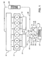
- Figure 1 shows an engine block 10 with six cylinders 11, that communicate in the conventional way with an intake branch pipe 12 and two separate exhaust gas branch pipes 13, 14. Each of these two exhaust gas branch pipes receives exhaust gases from three of the cylinders. The exhaust gases are taken via separate pipes 15, 16 to a turbine 17 in a high-pressure turbo unit 18 that comprises a compressor 19 mounted on a common shaft with the turbine 17.
- the exhaust gases are taken, via a duct 20 with an exhaust gas pressure regulator 20a, to a turbine 21 in a low-pressure turbo unit 22 that comprises a compressor 23 mounted on a common shaft with the turbine 21.
- the exhaust gases are finally taken via a pipe 24 to the engine's exhaust gas system, that can comprise units for after-treatment of the exhaust gases.
- Filtered intake air is taken into the engine via the pipe 25 and is taken to the compressor 23 of the low-pressure turbo unit 22.
- a pipe 26 takes the intake air to the compressor 19 of the high-pressure turbo unit 18 via a first intercooler 27. After this charging in two stages with intercooling, the intake air is taken to a second intercooler 29 via the pipe 28, after which the intake air reaches the intake branch pipe 12 via the pipe 30.
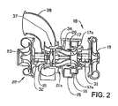
- the turbo charging system is shown in greater detail in Figure 2 that shows clearly the double, spiral intakes 15, 16 to the high-pressure turbine 17, each of which supplies half the turbine with gas flow via intake guides 17a.
- the high-pressure turbine 17 is of the radial type and is connected to the low-pressure turbine 21 via the short intermediate duct 20 that is able to be used due to the fact that the low-pressure turbine is of the axial type. This short flow path minimizes pressure losses between the turbine stages.
- the high-pressure turbine 17 is mounted on the shaft 31 together with the high-pressure compressor 19.
- the low-pressure turbine 21 is mounted on the shaft 32 together with the low-pressure compressor 23.
- the two turbo units 18, 22 are oriented along essentially the same longitudinal axis.
- the intermediate duct 20 is equipped with seals that counteract internal stresses and leakage by allowing a certain degree of axial and radial movement that takes up thermal forces and a certain degree of assembly tolerances.
- the exhaust gas pressure regulator 20a is located inside the duct 20 and will be described in greater detail below.
- the low-pressure turbine of the axial type is provided with a stator ring 34 with, intake guides.
- the high-pressure compressor 19 is of the radial type.
- An outlet diffuser 37 is placed after the low-pressure turbine 21 in order to recover dynamic pressure from the turbine.
- the diffuser opens into an exhaust gas collector 38 that directs the exhaust gases out to the exhaust gas pipe 24.
- the design of the exhaust gas pressure regulator 20a is shown in greater detail in Figures 3 and 4 , that show that the duct 20 has a circular cross section that is constructed of an outer wall 39 that is symmetrical around its axis of rotation and that has a cross section that increases in the direction towards the low-pressure turbine 21, and a central part 40 arranged concentrically inside the wall 39 with a cross section that similarly increases in the direction towards the low-pressure turbine.
- the central part 40 is mounted at a distance from the stator ring 34 on the end of a shaft 41 that is attached to the stator ring, and comprises a control piston 42 that is mounted on the shaft 41 in such a way that it can move.
- the control piston 42 comprises an inner piston chamber 43 with an outer valve sleeve 44. This is designed as an open cylinder with an outer wall surface and an inner wall surface.
- the control piston 42 can move axially between the central part and the outer wall 39 to regulate the flow area of the duct 20, against the effect of a helical compression spring 45.
- the control piston 42 and the shaft 41 together form the circular chamber 43 that is connected to a connection for pressurized medium (not shown in the figures) on the outside of the exhaust gas pressure regulator, via a duct 47 for pressurized medium that runs partly through a part of the shaft 41 that has a larger diameter and partly through the stator ring 34.
- the control piston 42 is thus able to be moved with the valve sleeve 44 between an inactive opening position and an active closing position by the effect of a pressurized medium, for example compressed air, that acts in the opposite direction to the direction of the force of the compression spring.
- a pressurized medium for example compressed air
- the valve sleeve 44 forms an axial extension of the central part 40 between the central part and the stator ring 34.
- an inner wall surface of the valve sleeve 44 forms an axial extension of the outer wall 39 between the outer wall and the central part 40.
- a circular end face 48 of the control piston 42 forms a piston surface that slides with a sealing fit inside a cylindrical part 49 of the central part 40 during the movement of the control piston.
- the inside of the central part thereby forms a chamber 50 that communicates with the pressure that is immediately downstream of the high-pressure turbine 17 via a duct 51.
- the exhaust gas pressure regulator described above is thus self-regulating and opens automatically when there is a certain pressure on the upstream side.
- the pressure can be built up rapidly upstream of the exhaust gas pressure regulator, due to the seal being gas-tight.
- the invention is described above in an application with a two-stage turbo charging system for supercharging of the internal combustion engine.
- the invention can be used in an application with a turbo charger unit and a turbo compound unit, where force can be transferred between the turbo compound unit and the crankshaft of the internal combustion engine in order to utilize the kinetic energy for different purposes.
- the invention is described in association with a six-cylinder diesel engine, but the system can be utilized with all the different piston engines from one cylinder and upwards, and with two-stroke or four-stroke engines.
- the invention can also be used with marine engines and with engines that have different piston stroke volumes to those mentioned above.
- An embodiment with a low-pressure turbine of the axial type has been described above, but the invention can also be used with a low-pressure turbine of the radial type.
- Other means than pneumatic can be used for operating the valve sleeve, for example mechanical means.
Landscapes
- Engineering & Computer Science (AREA)
- Chemical & Material Sciences (AREA)
- Combustion & Propulsion (AREA)
- Mechanical Engineering (AREA)
- General Engineering & Computer Science (AREA)
- Supercharger (AREA)
- Control Of Turbines (AREA)
Priority Applications (1)
| Application Number | Priority Date | Filing Date | Title |
|---|---|---|---|
| EP08021613.8A EP2037098B1 (de) | 2005-11-22 | 2005-11-22 | Turbocompound-Brennkraftmaschine |
Applications Claiming Priority (3)
| Application Number | Priority Date | Filing Date | Title |
|---|---|---|---|
| EP20050809977 EP1954929B1 (de) | 2005-11-22 | 2005-11-22 | Verbrennungsmotor mit zweistufigem turboladesystem |
| PCT/SE2005/001749 WO2007061339A1 (en) | 2005-11-22 | 2005-11-22 | Internal combustion engine with two-stage turbo charging system |
| EP08021613.8A EP2037098B1 (de) | 2005-11-22 | 2005-11-22 | Turbocompound-Brennkraftmaschine |
Related Parent Applications (1)
| Application Number | Title | Priority Date | Filing Date |
|---|---|---|---|
| EP20050809977 Division EP1954929B1 (de) | 2005-11-22 | 2005-11-22 | Verbrennungsmotor mit zweistufigem turboladesystem |
Publications (3)
| Publication Number | Publication Date |
|---|---|
| EP2037098A2 true EP2037098A2 (de) | 2009-03-18 |
| EP2037098A3 EP2037098A3 (de) | 2009-05-06 |
| EP2037098B1 EP2037098B1 (de) | 2016-06-15 |
Family
ID=38067461
Family Applications (2)
| Application Number | Title | Priority Date | Filing Date |
|---|---|---|---|
| EP08021613.8A Expired - Lifetime EP2037098B1 (de) | 2005-11-22 | 2005-11-22 | Turbocompound-Brennkraftmaschine |
| EP20050809977 Expired - Lifetime EP1954929B1 (de) | 2005-11-22 | 2005-11-22 | Verbrennungsmotor mit zweistufigem turboladesystem |
Family Applications After (1)
| Application Number | Title | Priority Date | Filing Date |
|---|---|---|---|
| EP20050809977 Expired - Lifetime EP1954929B1 (de) | 2005-11-22 | 2005-11-22 | Verbrennungsmotor mit zweistufigem turboladesystem |
Country Status (7)
| Country | Link |
|---|---|
| US (1) | US8333073B2 (de) |
| EP (2) | EP2037098B1 (de) |
| JP (1) | JP5036724B2 (de) |
| CN (1) | CN101313135B (de) |
| AT (1) | ATE546625T1 (de) |
| BR (1) | BRPI0520694B1 (de) |
| WO (1) | WO2007061339A1 (de) |
Families Citing this family (18)
| Publication number | Priority date | Publication date | Assignee | Title |
|---|---|---|---|---|
| DE102009046940B4 (de) * | 2009-11-20 | 2014-06-18 | Mtu Friedrichshafen Gmbh | Mehrstufige Aufladegruppe, Aufladesystem und Brennkraftmaschine, jeweils mit der mehrstufigen Aufladegruppe |
| EP2336571A1 (de) * | 2009-12-15 | 2011-06-22 | Perkins Engines Company Limited | System zur Verringerung des Verdichterölverbrauchs |
| KR101294050B1 (ko) * | 2010-09-30 | 2013-08-07 | 현대자동차주식회사 | 터보 랙 개선 장치 |
| US20120227400A1 (en) * | 2011-03-09 | 2012-09-13 | General Electric Company | Method and system for improving efficiency of multistage turbocharger |
| DE102011007386B4 (de) | 2011-04-14 | 2016-08-18 | Man Diesel & Turbo Se | Abgasnutzturbine, Abwärmerückgewinnungssystem und Verfahren zum Betreiben eines Abwärmerückgewinnungssystems |
| DE102011007638B4 (de) * | 2011-04-19 | 2026-01-22 | Everllence Se | Turboladeranordnung |
| US8959913B2 (en) * | 2011-09-15 | 2015-02-24 | General Electric Company | Systems and apparatus for transferring fluid flow |
| DE102011115296A1 (de) * | 2011-09-29 | 2013-04-04 | Mtu Friedrichshafen Gmbh | Zweistufige Aufladevorrichtung |
| CN102606285A (zh) * | 2012-04-07 | 2012-07-25 | 潍坊富源增压器有限公司 | 两级增压的涡轮增压器 |
| CN103437908A (zh) * | 2012-08-01 | 2013-12-11 | 摩尔动力(北京)技术股份有限公司 | 深度压缩单元发动机 |
| BR112015024905A2 (pt) | 2013-03-27 | 2017-07-18 | Volvo Truck Corp | um regulador de pressão de gás de exaustão |
| CN103410601A (zh) * | 2013-08-22 | 2013-11-27 | 湖南天雁机械有限责任公司 | 采用可变截面增压器的两级涡轮增压器 |
| US9534534B2 (en) | 2013-08-28 | 2017-01-03 | Deere & Company | Power system including a variable geometry turbocompound turbine |
| BR112016028811A2 (pt) * | 2014-06-10 | 2017-08-22 | Volvo Truck Corp | um sistema de turbina |
| US10436107B2 (en) | 2015-05-29 | 2019-10-08 | Volvo Truck Corporation | Exhaust gas pressure regulator for a combustion engine |
| US9759128B2 (en) | 2015-06-16 | 2017-09-12 | Pratt & Whitney Canada Corp. | Compound engine assembly with exhaust pipe nozzle |
| CN112334640A (zh) * | 2018-04-17 | 2021-02-05 | Abb瑞士有限公司 | 多级涡轮增压器装置 |
| CN109356711A (zh) * | 2018-12-12 | 2019-02-19 | 中国北方发动机研究所(天津) | 一种可变排气涡轮 |
Family Cites Families (19)
| Publication number | Priority date | Publication date | Assignee | Title |
|---|---|---|---|---|
| DE962764C (de) * | 1954-09-10 | 1957-04-25 | Maschf Augsburg Nuernberg Ag | Brennkraftmaschine mit Abgasturboaufladung |
| FR1397178A (fr) * | 1963-11-14 | 1965-04-30 | Nordberg Manufacturing Co | Moteur à combustion interne à forte suralimentation |
| CH579708A5 (de) * | 1973-10-16 | 1976-09-15 | Semt | |
| US3955595A (en) * | 1973-11-15 | 1976-05-11 | Powers Regulator Company | Automatic fluid flow regulator |
| US4096697A (en) * | 1974-06-28 | 1978-06-27 | Societe D'etudes De Machines Thermiques S.E.M.T. | Method and means for conditioning the intake air of a supercharged, low-compression ratio diesel engine |
| US3975911A (en) * | 1974-12-27 | 1976-08-24 | Jury Borisovich Morgulis | Turbocharger |
| US4100742A (en) * | 1976-12-09 | 1978-07-18 | The United States Of America As Represented By The Secretary Of The Army | Turbocompound engine with turbocharger control |
| FR2474193A1 (fr) * | 1980-01-21 | 1981-07-24 | Inst Francais Du Petrole | Dispositif regulateur de la pression d'un fluide |
| US4499731A (en) * | 1981-12-09 | 1985-02-19 | Bbc Brown, Boveri & Company, Limited | Controllable exhaust gas turbocharger |
| JPS61277818A (ja) * | 1985-05-31 | 1986-12-08 | Nissan Motor Co Ltd | 多段式タ−ボ過給エンジン |
| JPH01182533A (ja) | 1988-01-13 | 1989-07-20 | Hino Motors Ltd | 過給機付エンジンの排気ブレーキ装置 |
| DE3807372C2 (de) * | 1988-03-07 | 1996-12-12 | Asea Brown Boveri | Verbrennungsmotor mit zweistufigem Abgasturbolader und Nutzturbine |
| US5119633A (en) * | 1990-09-25 | 1992-06-09 | Cummins Engine Company, Inc. | Power turbine bypass for improved compression braking |
| DE4231474C1 (de) * | 1992-09-19 | 1994-01-20 | Mtu Friedrichshafen Gmbh | Aufgeladene Brennkraftmaschine mit einer Nutzturbine |
| JPH0814055A (ja) * | 1994-06-28 | 1996-01-16 | Isuzu Motors Ltd | 多段式ターボ過給エンジン |
| DE19514572C2 (de) * | 1995-04-20 | 1997-04-30 | Man Nutzfahrzeuge Ag | Aufgeladene Brennkraftmaschine |
| US5845748A (en) * | 1996-12-04 | 1998-12-08 | Diesel Engine Retarders, Inc. | Low restriction exhaust brake |
| EP0878633B1 (de) * | 1997-05-17 | 2004-12-08 | DaimlerChrysler AG | Wellengelenk |
| US7600380B2 (en) * | 2005-05-10 | 2009-10-13 | Borgwarner Inc. | Valve regulation for turbocharger |
-
2005
- 2005-11-22 WO PCT/SE2005/001749 patent/WO2007061339A1/en not_active Ceased
- 2005-11-22 BR BRPI0520694A patent/BRPI0520694B1/pt not_active IP Right Cessation
- 2005-11-22 CN CN2005800521281A patent/CN101313135B/zh not_active Expired - Fee Related
- 2005-11-22 EP EP08021613.8A patent/EP2037098B1/de not_active Expired - Lifetime
- 2005-11-22 US US12/094,477 patent/US8333073B2/en not_active Expired - Fee Related
- 2005-11-22 JP JP2008542270A patent/JP5036724B2/ja not_active Expired - Fee Related
- 2005-11-22 AT AT05809977T patent/ATE546625T1/de active
- 2005-11-22 EP EP20050809977 patent/EP1954929B1/de not_active Expired - Lifetime
Non-Patent Citations (1)
| Title |
|---|
| None |
Also Published As
| Publication number | Publication date |
|---|---|
| EP1954929B1 (de) | 2012-02-22 |
| US8333073B2 (en) | 2012-12-18 |
| EP2037098B1 (de) | 2016-06-15 |
| BRPI0520694B1 (pt) | 2019-02-05 |
| WO2007061339A1 (en) | 2007-05-31 |
| JP5036724B2 (ja) | 2012-09-26 |
| CN101313135B (zh) | 2013-02-06 |
| CN101313135A (zh) | 2008-11-26 |
| JP2009516807A (ja) | 2009-04-23 |
| BRPI0520694A2 (pt) | 2009-05-19 |
| ATE546625T1 (de) | 2012-03-15 |
| EP2037098A3 (de) | 2009-05-06 |
| US20090217662A1 (en) | 2009-09-03 |
| EP1954929A1 (de) | 2008-08-13 |
Similar Documents
| Publication | Publication Date | Title |
|---|---|---|
| EP2037098B1 (de) | Turbocompound-Brennkraftmaschine | |
| CN100402812C (zh) | 用于内燃机的涡轮增压器系统 | |
| US7360362B2 (en) | Two-stage turbocharger system with integrated exhaust manifold and bypass assembly | |
| KR101518013B1 (ko) | 터보차징과 배기 가스 재순환 사이의 분배된 배기 가스 흐름의 제어 | |
| JP5315416B2 (ja) | エンジン用の排気構造 | |
| JP4387411B2 (ja) | 回転軸が事実上同軸の二つの直列に配置したターボユニットを有する内燃エンジンのためのターボコンプレッサシステム | |
| CN102414419B (zh) | 涡轮增压器 | |
| US10132252B2 (en) | Engine system | |
| CN101341320A (zh) | 多级排气涡轮增压器 | |
| GB2034815A (en) | Supercharge internal-combustion engine | |
| US9068474B2 (en) | Turbine housing | |
| US10502219B2 (en) | Supercharging device for a combustion engine | |
| CN207813733U (zh) | 一种双涡轮双蜗管的二级涡轮增压器 | |
| JPS6240093Y2 (de) | ||
| US6308693B1 (en) | Supercharger for automobile | |
| RU158763U1 (ru) | Двигатель внутреннего сгорания с наддувом | |
| CN105358802A (zh) | 发动机的涡轮增压系统 | |
| WO2018092257A1 (ja) | 内燃機関の過給装置 |
Legal Events
| Date | Code | Title | Description |
|---|---|---|---|
| PUAI | Public reference made under article 153(3) epc to a published international application that has entered the european phase |
Free format text: ORIGINAL CODE: 0009012 |
|
| AC | Divisional application: reference to earlier application |
Ref document number: 1954929 Country of ref document: EP Kind code of ref document: P |
|
| AK | Designated contracting states |
Kind code of ref document: A2 Designated state(s): AT BE BG CH CY CZ DE DK EE ES FI FR GB GR HU IE IS IT LI LT LU LV MC NL PL PT RO SE SI SK TR |
|
| AX | Request for extension of the european patent |
Extension state: AL BA HR MK YU |
|
| PUAL | Search report despatched |
Free format text: ORIGINAL CODE: 0009013 |
|
| AK | Designated contracting states |
Kind code of ref document: A3 Designated state(s): AT BE BG CH CY CZ DE DK EE ES FI FR GB GR HU IE IS IT LI LT LU LV MC NL PL PT RO SE SI SK TR |
|
| AX | Request for extension of the european patent |
Extension state: AL BA HR MK YU |
|
| 17P | Request for examination filed |
Effective date: 20091106 |
|
| AKX | Designation fees paid |
Designated state(s): AT BE BG CH CY CZ DE DK EE ES FI FR GB GR HU IE IS IT LI LT LU LV MC NL PL PT RO SE SI SK TR |
|
| 17Q | First examination report despatched |
Effective date: 20110321 |
|
| GRAP | Despatch of communication of intention to grant a patent |
Free format text: ORIGINAL CODE: EPIDOSNIGR1 |
|
| INTG | Intention to grant announced |
Effective date: 20160104 |
|
| GRAS | Grant fee paid |
Free format text: ORIGINAL CODE: EPIDOSNIGR3 |
|
| GRAA | (expected) grant |
Free format text: ORIGINAL CODE: 0009210 |
|
| AC | Divisional application: reference to earlier application |
Ref document number: 1954929 Country of ref document: EP Kind code of ref document: P |
|
| AK | Designated contracting states |
Kind code of ref document: B1 Designated state(s): AT BE BG CH CY CZ DE DK EE ES FI FR GB GR HU IE IS IT LI LT LU LV MC NL PL PT RO SE SI SK TR |
|
| REG | Reference to a national code |
Ref country code: CH Ref legal event code: EP Ref country code: GB Ref legal event code: FG4D |
|
| REG | Reference to a national code |
Ref country code: IE Ref legal event code: FG4D |
|
| REG | Reference to a national code |
Ref country code: AT Ref legal event code: REF Ref document number: 806632 Country of ref document: AT Kind code of ref document: T Effective date: 20160715 |
|
| REG | Reference to a national code |
Ref country code: DE Ref legal event code: R096 Ref document number: 602005049543 Country of ref document: DE |
|
| REG | Reference to a national code |
Ref country code: NL Ref legal event code: FP |
|
| REG | Reference to a national code |
Ref country code: SE Ref legal event code: TRGR |
|
| REG | Reference to a national code |
Ref country code: LT Ref legal event code: MG4D |
|
| PG25 | Lapsed in a contracting state [announced via postgrant information from national office to epo] |
Ref country code: FI Free format text: LAPSE BECAUSE OF FAILURE TO SUBMIT A TRANSLATION OF THE DESCRIPTION OR TO PAY THE FEE WITHIN THE PRESCRIBED TIME-LIMIT Effective date: 20160615 Ref country code: LT Free format text: LAPSE BECAUSE OF FAILURE TO SUBMIT A TRANSLATION OF THE DESCRIPTION OR TO PAY THE FEE WITHIN THE PRESCRIBED TIME-LIMIT Effective date: 20160615 |
|
| REG | Reference to a national code |
Ref country code: AT Ref legal event code: MK05 Ref document number: 806632 Country of ref document: AT Kind code of ref document: T Effective date: 20160615 |
|
| REG | Reference to a national code |
Ref country code: FR Ref legal event code: PLFP Year of fee payment: 12 |
|
| PG25 | Lapsed in a contracting state [announced via postgrant information from national office to epo] |
Ref country code: LV Free format text: LAPSE BECAUSE OF FAILURE TO SUBMIT A TRANSLATION OF THE DESCRIPTION OR TO PAY THE FEE WITHIN THE PRESCRIBED TIME-LIMIT Effective date: 20160615 Ref country code: GR Free format text: LAPSE BECAUSE OF FAILURE TO SUBMIT A TRANSLATION OF THE DESCRIPTION OR TO PAY THE FEE WITHIN THE PRESCRIBED TIME-LIMIT Effective date: 20160916 |
|
| PG25 | Lapsed in a contracting state [announced via postgrant information from national office to epo] |
Ref country code: IS Free format text: LAPSE BECAUSE OF FAILURE TO SUBMIT A TRANSLATION OF THE DESCRIPTION OR TO PAY THE FEE WITHIN THE PRESCRIBED TIME-LIMIT Effective date: 20161015 Ref country code: CZ Free format text: LAPSE BECAUSE OF FAILURE TO SUBMIT A TRANSLATION OF THE DESCRIPTION OR TO PAY THE FEE WITHIN THE PRESCRIBED TIME-LIMIT Effective date: 20160615 Ref country code: SK Free format text: LAPSE BECAUSE OF FAILURE TO SUBMIT A TRANSLATION OF THE DESCRIPTION OR TO PAY THE FEE WITHIN THE PRESCRIBED TIME-LIMIT Effective date: 20160615 Ref country code: EE Free format text: LAPSE BECAUSE OF FAILURE TO SUBMIT A TRANSLATION OF THE DESCRIPTION OR TO PAY THE FEE WITHIN THE PRESCRIBED TIME-LIMIT Effective date: 20160615 Ref country code: RO Free format text: LAPSE BECAUSE OF FAILURE TO SUBMIT A TRANSLATION OF THE DESCRIPTION OR TO PAY THE FEE WITHIN THE PRESCRIBED TIME-LIMIT Effective date: 20160615 |
|
| PG25 | Lapsed in a contracting state [announced via postgrant information from national office to epo] |
Ref country code: AT Free format text: LAPSE BECAUSE OF FAILURE TO SUBMIT A TRANSLATION OF THE DESCRIPTION OR TO PAY THE FEE WITHIN THE PRESCRIBED TIME-LIMIT Effective date: 20160615 Ref country code: PL Free format text: LAPSE BECAUSE OF FAILURE TO SUBMIT A TRANSLATION OF THE DESCRIPTION OR TO PAY THE FEE WITHIN THE PRESCRIBED TIME-LIMIT Effective date: 20160615 Ref country code: BE Free format text: LAPSE BECAUSE OF FAILURE TO SUBMIT A TRANSLATION OF THE DESCRIPTION OR TO PAY THE FEE WITHIN THE PRESCRIBED TIME-LIMIT Effective date: 20160615 Ref country code: ES Free format text: LAPSE BECAUSE OF FAILURE TO SUBMIT A TRANSLATION OF THE DESCRIPTION OR TO PAY THE FEE WITHIN THE PRESCRIBED TIME-LIMIT Effective date: 20160615 Ref country code: PT Free format text: LAPSE BECAUSE OF FAILURE TO SUBMIT A TRANSLATION OF THE DESCRIPTION OR TO PAY THE FEE WITHIN THE PRESCRIBED TIME-LIMIT Effective date: 20161017 |
|
| REG | Reference to a national code |
Ref country code: DE Ref legal event code: R097 Ref document number: 602005049543 Country of ref document: DE |
|
| PLBE | No opposition filed within time limit |
Free format text: ORIGINAL CODE: 0009261 |
|
| STAA | Information on the status of an ep patent application or granted ep patent |
Free format text: STATUS: NO OPPOSITION FILED WITHIN TIME LIMIT |
|
| 26N | No opposition filed |
Effective date: 20170316 |
|
| PG25 | Lapsed in a contracting state [announced via postgrant information from national office to epo] |
Ref country code: DK Free format text: LAPSE BECAUSE OF FAILURE TO SUBMIT A TRANSLATION OF THE DESCRIPTION OR TO PAY THE FEE WITHIN THE PRESCRIBED TIME-LIMIT Effective date: 20160615 |
|
| REG | Reference to a national code |
Ref country code: CH Ref legal event code: PL |
|
| PG25 | Lapsed in a contracting state [announced via postgrant information from national office to epo] |
Ref country code: LI Free format text: LAPSE BECAUSE OF NON-PAYMENT OF DUE FEES Effective date: 20161130 Ref country code: CH Free format text: LAPSE BECAUSE OF NON-PAYMENT OF DUE FEES Effective date: 20161130 |
|
| REG | Reference to a national code |
Ref country code: IE Ref legal event code: MM4A |
|
| PG25 | Lapsed in a contracting state [announced via postgrant information from national office to epo] |
Ref country code: SI Free format text: LAPSE BECAUSE OF FAILURE TO SUBMIT A TRANSLATION OF THE DESCRIPTION OR TO PAY THE FEE WITHIN THE PRESCRIBED TIME-LIMIT Effective date: 20160615 |
|
| PG25 | Lapsed in a contracting state [announced via postgrant information from national office to epo] |
Ref country code: LU Free format text: LAPSE BECAUSE OF NON-PAYMENT OF DUE FEES Effective date: 20161130 |
|
| REG | Reference to a national code |
Ref country code: FR Ref legal event code: PLFP Year of fee payment: 13 |
|
| PG25 | Lapsed in a contracting state [announced via postgrant information from national office to epo] |
Ref country code: IE Free format text: LAPSE BECAUSE OF NON-PAYMENT OF DUE FEES Effective date: 20161122 |
|
| PG25 | Lapsed in a contracting state [announced via postgrant information from national office to epo] |
Ref country code: HU Free format text: LAPSE BECAUSE OF FAILURE TO SUBMIT A TRANSLATION OF THE DESCRIPTION OR TO PAY THE FEE WITHIN THE PRESCRIBED TIME-LIMIT; INVALID AB INITIO Effective date: 20051122 Ref country code: CY Free format text: LAPSE BECAUSE OF FAILURE TO SUBMIT A TRANSLATION OF THE DESCRIPTION OR TO PAY THE FEE WITHIN THE PRESCRIBED TIME-LIMIT Effective date: 20160615 |
|
| PG25 | Lapsed in a contracting state [announced via postgrant information from national office to epo] |
Ref country code: TR Free format text: LAPSE BECAUSE OF FAILURE TO SUBMIT A TRANSLATION OF THE DESCRIPTION OR TO PAY THE FEE WITHIN THE PRESCRIBED TIME-LIMIT Effective date: 20160615 Ref country code: MC Free format text: LAPSE BECAUSE OF FAILURE TO SUBMIT A TRANSLATION OF THE DESCRIPTION OR TO PAY THE FEE WITHIN THE PRESCRIBED TIME-LIMIT Effective date: 20160615 |
|
| PG25 | Lapsed in a contracting state [announced via postgrant information from national office to epo] |
Ref country code: BG Free format text: LAPSE BECAUSE OF FAILURE TO SUBMIT A TRANSLATION OF THE DESCRIPTION OR TO PAY THE FEE WITHIN THE PRESCRIBED TIME-LIMIT Effective date: 20160615 |
|
| PGFP | Annual fee paid to national office [announced via postgrant information from national office to epo] |
Ref country code: SE Payment date: 20221123 Year of fee payment: 18 Ref country code: NL Payment date: 20221124 Year of fee payment: 18 Ref country code: IT Payment date: 20221122 Year of fee payment: 18 Ref country code: GB Payment date: 20221122 Year of fee payment: 18 Ref country code: FR Payment date: 20221122 Year of fee payment: 18 Ref country code: DE Payment date: 20220527 Year of fee payment: 18 |
|
| REG | Reference to a national code |
Ref country code: DE Ref legal event code: R119 Ref document number: 602005049543 Country of ref document: DE |
|
| REG | Reference to a national code |
Ref country code: SE Ref legal event code: EUG |
|
| REG | Reference to a national code |
Ref country code: NL Ref legal event code: MM Effective date: 20231201 |
|
| GBPC | Gb: european patent ceased through non-payment of renewal fee |
Effective date: 20231122 |
|
| PG25 | Lapsed in a contracting state [announced via postgrant information from national office to epo] |
Ref country code: SE Free format text: LAPSE BECAUSE OF NON-PAYMENT OF DUE FEES Effective date: 20231123 |
|
| PG25 | Lapsed in a contracting state [announced via postgrant information from national office to epo] |
Ref country code: NL Free format text: LAPSE BECAUSE OF NON-PAYMENT OF DUE FEES Effective date: 20231201 |
|
| PG25 | Lapsed in a contracting state [announced via postgrant information from national office to epo] |
Ref country code: NL Free format text: LAPSE BECAUSE OF NON-PAYMENT OF DUE FEES Effective date: 20231201 |
|
| PG25 | Lapsed in a contracting state [announced via postgrant information from national office to epo] |
Ref country code: DE Free format text: LAPSE BECAUSE OF NON-PAYMENT OF DUE FEES Effective date: 20240601 |
|
| PG25 | Lapsed in a contracting state [announced via postgrant information from national office to epo] |
Ref country code: GB Free format text: LAPSE BECAUSE OF NON-PAYMENT OF DUE FEES Effective date: 20231122 |
|
| PG25 | Lapsed in a contracting state [announced via postgrant information from national office to epo] |
Ref country code: FR Free format text: LAPSE BECAUSE OF NON-PAYMENT OF DUE FEES Effective date: 20231130 |
|
| PG25 | Lapsed in a contracting state [announced via postgrant information from national office to epo] |
Ref country code: GB Free format text: LAPSE BECAUSE OF NON-PAYMENT OF DUE FEES Effective date: 20231122 Ref country code: FR Free format text: LAPSE BECAUSE OF NON-PAYMENT OF DUE FEES Effective date: 20231130 Ref country code: DE Free format text: LAPSE BECAUSE OF NON-PAYMENT OF DUE FEES Effective date: 20240601 |
|
| PG25 | Lapsed in a contracting state [announced via postgrant information from national office to epo] |
Ref country code: IT Free format text: LAPSE BECAUSE OF NON-PAYMENT OF DUE FEES Effective date: 20231122 |
|
| PG25 | Lapsed in a contracting state [announced via postgrant information from national office to epo] |
Ref country code: IT Free format text: LAPSE BECAUSE OF NON-PAYMENT OF DUE FEES Effective date: 20231122 |