EP2037074A2 - Device for at least partial shadowing - Google Patents
Device for at least partial shadowing Download PDFInfo
- Publication number
- EP2037074A2 EP2037074A2 EP08164247A EP08164247A EP2037074A2 EP 2037074 A2 EP2037074 A2 EP 2037074A2 EP 08164247 A EP08164247 A EP 08164247A EP 08164247 A EP08164247 A EP 08164247A EP 2037074 A2 EP2037074 A2 EP 2037074A2
- Authority
- EP
- European Patent Office
- Prior art keywords
- rail
- holding
- fastening means
- holding element
- holding elements
- Prior art date
- Legal status (The legal status is an assumption and is not a legal conclusion. Google has not performed a legal analysis and makes no representation as to the accuracy of the status listed.)
- Withdrawn
Links
Images


Classifications
-
- E—FIXED CONSTRUCTIONS
- E06—DOORS, WINDOWS, SHUTTERS, OR ROLLER BLINDS IN GENERAL; LADDERS
- E06B—FIXED OR MOVABLE CLOSURES FOR OPENINGS IN BUILDINGS, VEHICLES, FENCES OR LIKE ENCLOSURES IN GENERAL, e.g. DOORS, WINDOWS, BLINDS, GATES
- E06B9/00—Screening or protective devices for wall or similar openings, with or without operating or securing mechanisms; Closures of similar construction
- E06B9/24—Screens or other constructions affording protection against light, especially against sunshine; Similar screens for privacy or appearance; Slat blinds
- E06B9/26—Lamellar or like blinds, e.g. venetian blinds
- E06B9/262—Lamellar or like blinds, e.g. venetian blinds with flexibly-interconnected horizontal or vertical strips; Concertina blinds, i.e. upwardly folding flexible screens
-
- E—FIXED CONSTRUCTIONS
- E06—DOORS, WINDOWS, SHUTTERS, OR ROLLER BLINDS IN GENERAL; LADDERS
- E06B—FIXED OR MOVABLE CLOSURES FOR OPENINGS IN BUILDINGS, VEHICLES, FENCES OR LIKE ENCLOSURES IN GENERAL, e.g. DOORS, WINDOWS, BLINDS, GATES
- E06B9/00—Screening or protective devices for wall or similar openings, with or without operating or securing mechanisms; Closures of similar construction
- E06B9/24—Screens or other constructions affording protection against light, especially against sunshine; Similar screens for privacy or appearance; Slat blinds
- E06B9/26—Lamellar or like blinds, e.g. venetian blinds
- E06B9/28—Lamellar or like blinds, e.g. venetian blinds with horizontal lamellae, e.g. non-liftable
- E06B9/30—Lamellar or like blinds, e.g. venetian blinds with horizontal lamellae, e.g. non-liftable liftable
- E06B9/32—Operating, guiding, or securing devices therefor
- E06B9/327—Guides for raisable lamellar blinds with horizontal lamellae
-
- E—FIXED CONSTRUCTIONS
- E06—DOORS, WINDOWS, SHUTTERS, OR ROLLER BLINDS IN GENERAL; LADDERS
- E06B—FIXED OR MOVABLE CLOSURES FOR OPENINGS IN BUILDINGS, VEHICLES, FENCES OR LIKE ENCLOSURES IN GENERAL, e.g. DOORS, WINDOWS, BLINDS, GATES
- E06B9/00—Screening or protective devices for wall or similar openings, with or without operating or securing mechanisms; Closures of similar construction
- E06B9/24—Screens or other constructions affording protection against light, especially against sunshine; Similar screens for privacy or appearance; Slat blinds
- E06B9/26—Lamellar or like blinds, e.g. venetian blinds
- E06B9/262—Lamellar or like blinds, e.g. venetian blinds with flexibly-interconnected horizontal or vertical strips; Concertina blinds, i.e. upwardly folding flexible screens
- E06B2009/2625—Pleated screens, e.g. concertina- or accordion-like
Definitions
- the invention relates to a device, in particular pleated blind or blind, for at least partial shading with a first rail and a second rail, with a shading element arranged between the first rail and the second rail, with elongated first holding elements on which the first rail and the second rail are slidably held, wherein the first holding elements are arranged at right angles to the longitudinal axis of the rails at the opposite ends of the rails.
- Such a device is known from WO 2007/056781 A1 known.
- Such devices are used to at least partially cover openings of buildings. For example, pleats or blinds can reduce the incidence of light and / or serve as a screen.
- the devices are used, for example, in conjunction with windows or doors.
- the devices can also be used to delimit areas of space within a building.
- the window openings can be covered completely or even partially by means of the device. Due to the sliding first and second rail manifold adjustment options are given. Thus, for example, in the case of a window or a door, only the upper part of the opening can be covered, so that light can continue to be incident through the lower part of the opening, and thus only partial shading is achieved.
- the disadvantage here is that the rails can bend due to their total weight. Since the rails are held only laterally displaceable by means of the elongated first holding elements, the rails can bend in the middle. Especially when using a blind additional components must be included in at least one rail with, for example, to allow the adjustment of the individual slats. Due to the additional components, the weight of the rail inevitably increases. As a result, the risk of self-adjusting deflection of the rail is increased due to the greater total weight. Especially with wide openings to be covered there is a risk that the functionality of the device is impaired due to the sagging rails. As a result, the operation of the device can be disturbed to the point of uselessness.
- the problem underlying the invention is therefore to develop the aforementioned device such that a bending of the rails can be reliably avoided.
- the problem is solved by means of a device of the aforementioned type in that between the first holding elements at least one elongated second holding element is arranged at right angles to the longitudinal axis of the rails, wherein the first rail and / or the second rail is slidably held on the second holding element.
- the weight of the rails no longer needs to be borne solely by the first laterally arranged on the rail ends holding elements. Rather, the weight is now distributed to the first holding elements and the second holding element. Furthermore, a bending of the rails is thereby reliably avoided, that the second holding element is arranged between the first holding elements.
- the second holding element is arranged centrally between the first holding elements.
- a rail held at the outer ends undergoes its greatest deflection in the middle of the rail, since here the holding forces acting on the rail ends have the least influence.
- the particular arrangement that is particularly susceptible to deflection is used as an additional breakpoint by the central arrangement of the second holding element.
- several second holding elements for example, depending on the width of the device can be used. This makes it possible to use, for example, pleats or blinds with virtually any rail length or width of the device.
- a holding force acts from the second holding element on the first rail.
- the first rail if it is for example the upper rail, may have a higher total weight than the second rail, which may be a lower rail, due to additional components. Due to the additional holding force bending of the first and heavier rail can be reliably avoided. As a result, a permanent functioning of the device is ensured.
- one, in particular four, deflections are assigned to the second holding element in the first rail.
- the deflections are protected due to the arrangement in the first rail from disturbing influences such as impurities.
- further, in particular four, deflections are provided in the second rail for the second holding element.
- the second holding element can also be guided expediently with respect to the second rail.
- the second holding element is guided at right angles to the longitudinal axis of the second rail through a first opening in the second rail.
- the supply of the second holding element to the second rail is clearly defined and defined.
- the second holding element is guided by means of a first deflection in the longitudinal direction of the second rail and in the direction of the remote rail end and by means of a second deflection at right angles to the longitudinal axis of the second rail through a second opening from the second rail in the direction of the first rail.
- the leadership of the second holding element within the second rail and with respect to the deflection provided there is clearly defined. Due to this guidance acts in the area of second deflection a holding force on the second rail. This reduces the risk of deflection of the second rail.
- the second holding element is guided at right angles to the longitudinal axis of the first rail through a third opening in the first rail. Through the third opening, the supply of the second holding element is clearly defined and fixed in the first rail.
- the second holding element is guided by means of a third deflection in the longitudinal direction of the first rail and in the direction of the remote rail end and by means of a fourth deflection at right angles to the longitudinal axis of the first rail through a fourth opening from the first rail. Due to the previously given guidance of the second holding element results that in the region of the fourth deflection an additional holding force acts on the first rail.
- the first rail and / or second rail is held displaceable by means of the second holding element in addition to the first holding elements.
- the deflections are made of synthetic resin material, in particular high-strength polyetherimide (PEI).
- PEI polyetherimide
- the risk of wear and material fatigue can be significantly reduced.
- a durable and reliable operation of the device is favored.
- the second holding element is guided through openings of the shading element. This makes it possible to reliably fix the position of the shading element between the first rail and the second rail. This ensures that the shading element does not emerge or bulge out of a plane imagined between the first rail and the second rail, for example due to a gust of wind.
- additional third holding elements are provided in addition to the first holding elements and the second holding element.
- the third holding elements may be provided for additional guidance of the shading element. As a result, the position of the shading element between the first rail and the second rail can be determined.
- the holding elements are cord-like, in particular designed as cords.
- strings as holding elements in devices of the type mentioned is known and proven. By using such cords, the functionality of the device is permanently guaranteed.
- the first holding elements on a C-threading preferably have a Z-threading.
- Such threading techniques have proven useful when used in pleats or blinds.
- the first rail and the second rail are preferably displaceable independently of one another, in particular relative to one another, along the retaining elements. This results in a particularly wide variety of possible settings. Thus, for example, windows or doors can be partially or completely covered not only from above, but it is also possible to cover such openings only in a lower or central area.
- fastening means are provided for the holding elements. This makes it possible to pre-assemble the device as far as possible. When installing the device only the fasteners need to be attached. The easier assembly reduces the cost and the risk of adjustment errors.
- fastening means are assigned to the mutually remote ends of the rails and spaced at right angles from the rails in the displacement direction, wherein the fastening means are preferably arranged on an inner reveal.
- the fastening means can be attached to the glazing beads of a window or door.
- a further fastening means is provided for the second retaining element, and preferably the further fastening means is arranged centrally between the first fastening means, in particular facing the first rail.
- a first fastening means are designed as a starting point and a second fastening means as an end point for the retaining element, and preferably the starting point and the end point correspond to the fastening means facing the second rail.
- the starting point and end point of the second holding element are clearly defined.
- the holding element is guided from the starting point via the second rail to the first rail. Will from the first rail the second holding element is guided to the further fastening means in order subsequently to be guided again by the further fastening means to the first rail. Subsequently, the second holding element is guided from the first rail to the second rail and finally via the second rail to the end point.
- the second holding element by means of the further fastening means, in particular by 180 °, deflected. Only because of such a deflection can the second holding element be returned from the starting point to the end point.
- the, in particular the further, fastening means made of synthetic resin material, in particular polycarbonate, are produced.
- the processing of such materials is known and proven.
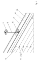
- Fig. 1 shows a device 10 according to the invention, wherein the device 10 is formed here as a pleat 10.
- the device 10 may also be a venetian blind.
- the device 10 has a first rail 11 and a second rail 12. Between the first rail 11 and the second rail 12, a shading element 13 is arranged.
- the shading element 13 is a pleated element 13.
- the device 10 has first elongate retaining elements 14, on which the first rail 11 and the second rail 12 are held displaceably.
- the first holding elements 14 are at right angles to the longitudinal axis of the rails 11, 12 at the opposite ends Ends of the rails 11, 12 are arranged.
- an elongate second holding element 15 is arranged at right angles to the longitudinal axis of the rails 11, 12.
- the second holding element 15 is arranged centrally and at equal distances from the mutually remote ends of the rails 11, 12.
- the device 10 has third holding elements 16.
- All retaining elements 14, 15, 16 are associated with a first fastening means 17 and a second fastening means 18.
- the first holding elements 14 and third holding elements 16 are associated with a third fastening means 19 and a fourth fastening means 20.
- the second holding element 15, however, is associated with a further fastening means 21.
- the fastening means 17, 18, 19, 20, 21 are attached to a glass strips, not shown, for example, a window in a known manner.
- the shading element 13 has a plurality of openings 22, through which the holding elements 14, 15, 16 are guided.
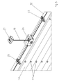
- Fig. 2 1 shows a schematic representation of the device 10 according to the invention and illustrates a possible guidance of the retaining elements 14, 15 and 16.
- the first retaining elements 14 are guided in a known C-threading from the fastening means 17 to the fastening means 19 or from the fastening means 18 to the fastening means 20.
- the third holding elements 16 are guided by means of a likewise known Z-threading from the fastening means 17 to the fastening means 20 and from the fastening means 18 to the fastening means 19. In this case, two deflections occur within the first rail 11 and the second rail 12.
- the second holding element 15 is introduced starting from the fastening means 17 through an opening 23 in the second rail 12.
- the second holding element 15 is guided in the longitudinal direction of the second rail 12 and in the direction of the remote rail end.
- the second holding element 15 is guided by means of a second deflection at right angles to the longitudinal axis of the second rail 15 through a second opening 24 from the second rail 12 in the direction of the first rail 11.
- the second holding element 15 is guided by apertures 22 of the shading element 13, not shown here, in order to then be guided through an opening 25 in the first rail 11. There, the second holding element 15 is guided by means of a third deflection in the longitudinal direction of the first rail 11 and in the direction of the rail center and by means of a fourth deflection at right angles to Longitudinal axis of the first rail 11 is guided by a fourth opening 26 from the first rail 11.
- the second holding element 15 is then guided to the further fastening means 21 and deflected there by 180 °.
- the second holding member 15 is returned again in the direction of the opening 26 and in the first rail 11, to then be guided over a further deflection in the longitudinal direction of the first rail 11 and from the opening 25 away.
- the second holding element 15 is guided by means of a further deflection through an opening 27 from the first rail 11 in the direction of the second rail 12.
- the second retaining element 15 re-enters the second rail 12 via an opening 28.
- a deflection first takes place from the opening 24 away from the rail end, in order then to be guided via a further deflection out of the opening 29 out of the second rail 12 and in the direction of the fastening means 18.
- the third holding elements 16 are held by spring compressor 30 to tension.
- the required tension for the holding elements 14, 16 is effected and inaccuracies in the installation of the device 10 can be compensated.
- the Fig. 3 illustrates another possible threading of the holding elements 14, 15 and 16. While the openings 24, 25, 27 and 28 according to the Fig. 2 are arranged in a central region of the first rail 11 and the second rail 12, the openings 24, 25, 27 and 28 are according to the Fig. 3 arranged in an edge region of the rails.
- the Fig. 4 shows a section of the perspective side view according to the Fig. 1 and illustrates how the second holding member 15 is guided out of the opening 26 in the direction of the further fastening means 21 and from this again back to the opening 26. Furthermore, it can be seen that the first rail 11 consists of a base rail 32 and a cover rail 33.
- the Fig. 5 shows the section according to the Fig. 4 This now shows how the second holding element 15 is initially deflected through the opening 25 in the direction of the opening 26 in order to be guided in the direction of the further fastening means 21 after renewed deflection. After the 180 ° deflection by means of the further fastening means 21, the second holding element 15 is again guided through the opening 26 and now in the direction of the opening 27.
Landscapes
- Engineering & Computer Science (AREA)
- Structural Engineering (AREA)
- Architecture (AREA)
- Civil Engineering (AREA)
- Blinds (AREA)
Abstract
Description
Die Erfindung betrifft eine Vorrichtung, insbesondere Plissee oder Jalousie, zum mindestens teilweisen Verschatten mit einer ersten Schiene und einer zweiten Schiene, mit einem zwischen der ersten Schiene und der zweiten Schiene angeordneten Verschattungselement, mit lang gestreckten ersten Halteelementen, an denen die erste Schiene und die zweite Schiene verschiebbar gehalten sind, wobei die ersten Halteelemente rechtwinklig zur Längsachse der Schienen an den voneinander abgewandten Enden der Schienen angeordnet sind.The invention relates to a device, in particular pleated blind or blind, for at least partial shading with a first rail and a second rail, with a shading element arranged between the first rail and the second rail, with elongated first holding elements on which the first rail and the second rail are slidably held, wherein the first holding elements are arranged at right angles to the longitudinal axis of the rails at the opposite ends of the rails.
Eine derartige Vorrichtung ist aus der
Solche Vorrichtungen werden verwendet, um Öffnungen von Gebäuden zumindest teilweise abzudecken. So können beispielsweise Plissees oder Jalousien den Lichteinfall mindern und/oder als Sichtschutz dienen. Die Vorrichtungen werden beispielsweise im Verbund mit Fenstern oder Türen verwendet. Darüber hinaus können die Vorrichtungen auch zur Abgrenzung von Raumbereichen innerhalb eines Gebäudes genutzt werden. Abhängig von den individuellen Bedürfnissen können beispielsweise die Fensteröffnungen mittels der Vorrichtung vollständig oder auch nur teilweise abgedeckt werden. Durch die verschiebbare erste und zweite Schiene sind vielfältige Einstellmöglichkeiten gegeben. So kann beispielsweise bei einem Fenster oder einer Tür nur der obere Teil der Öffnung abgedeckt werden, so dass durch den unteren Teil der Öffnung weiterhin Licht einfallen kann und somit nur eine teilweise Verschattung erreicht wird. Genauso ist es möglich nur den unteren Teil abzudecken, während der obere Teil der Öffnung weiterhin einen Lichteinfall ermöglicht. Ferner kann nur ein mittlerer Bereich der Öffnung abgedeckt werden, so dass ein Lichteinfall sowohl durch einen oberen als auch durch einen unteren Bereich der Öffnung erfolgen kann.Such devices are used to at least partially cover openings of buildings. For example, pleats or blinds can reduce the incidence of light and / or serve as a screen. The devices are used, for example, in conjunction with windows or doors. In addition, the devices can also be used to delimit areas of space within a building. Depending on the individual needs For example, the window openings can be covered completely or even partially by means of the device. Due to the sliding first and second rail manifold adjustment options are given. Thus, for example, in the case of a window or a door, only the upper part of the opening can be covered, so that light can continue to be incident through the lower part of the opening, and thus only partial shading is achieved. Similarly, it is possible to cover only the lower part, while the upper part of the opening continues to allow light to enter. Furthermore, only a central region of the opening can be covered, so that a light incidence can take place both through an upper and through a lower region of the opening.
Nachteilig ist hierbei, dass sich die Schienen aufgrund ihres Gesamtgewichtes durchbiegen können. Da die Schienen lediglich seitlich mittels der lang gestreckten ersten Halteelemente verschiebbar gehalten sind, können sich die Schienen in der Mitte durchbiegen. Gerade bei der Verwendung einer Jalousie müssen zusätzliche Bauelemente in zumindest eine Schiene mit aufgenommen werden, um beispielsweise das Verstellen der einzelnen Lamellen zu ermöglichen. Aufgrund der zusätzlichen Bauelemente nimmt das Gewicht der Schiene zwangsläufig zu. Hierdurch wird die Gefahr einer sich einstellenden Durchbiegung der Schiene aufgrund des größeren Gesamtgewichtes erhöht. Vor allem bei breiten abzudeckenden Öffnungen besteht die Gefahr, dass die Funktionstüchtigkeit der Vorrichtung aufgrund der sich durchbiegenden Schienen beeinträchtigt wird. Hierdurch kann der Betrieb der Vorrichtung bis hin zur Unbrauchbarkeit gestört werden.The disadvantage here is that the rails can bend due to their total weight. Since the rails are held only laterally displaceable by means of the elongated first holding elements, the rails can bend in the middle. Especially when using a blind additional components must be included in at least one rail with, for example, to allow the adjustment of the individual slats. Due to the additional components, the weight of the rail inevitably increases. As a result, the risk of self-adjusting deflection of the rail is increased due to the greater total weight. Especially with wide openings to be covered there is a risk that the functionality of the device is impaired due to the sagging rails. As a result, the operation of the device can be disturbed to the point of uselessness.
Das der Erfindung zugrunde liegende Problem ist es daher, die vorgenannte Vorrichtung derart weiter zu entwickeln, dass ein Durchbiegen der Schienen zuverlässig vermieden werden kann.The problem underlying the invention is therefore to develop the aforementioned device such that a bending of the rails can be reliably avoided.
Das Problem wird mittels einer Vorrichtung der vorgenannten Art dadurch gelöst, dass zwischen den ersten Halteelementen mindestens ein lang gestrecktes zweites Halteelement rechtwinklig zur Längsachse der Schienen angeordnet ist, wobei die erste Schiene und/oder die zweite Schiene verschiebbar an dem zweiten Halteelement gehalten ist.The problem is solved by means of a device of the aforementioned type in that between the first holding elements at least one elongated second holding element is arranged at right angles to the longitudinal axis of the rails, wherein the first rail and / or the second rail is slidably held on the second holding element.
Hierbei ist von Vorteil, dass das Gewicht der Schienen nicht mehr allein von den ersten seitlich an den Schienenenden angeordneten Halteelementen getragen werden muss. Vielmehr wird das Gewicht nun auf die ersten Halteelemente und das zweite Halteelement verteilt. Ferner wird ein Durchbiegen der Schienen dadurch zuverlässig vermieden, dass das zweite Halteelement zwischen den ersten Halteelementen angeordnet ist.It is advantageous that the weight of the rails no longer needs to be borne solely by the first laterally arranged on the rail ends holding elements. Rather, the weight is now distributed to the first holding elements and the second holding element. Furthermore, a bending of the rails is thereby reliably avoided, that the second holding element is arranged between the first holding elements.
Nach einer vorteilhaften Weiterbildung ist das zweite Halteelement mittig zwischen den ersten Halteelementen angeordnet. Eine an den äußeren Enden gehaltene Schiene erfährt in der Mitte der Schiene ihre größte Durchbiegung, da hier die auf die Schienenenden wirkenden Haltekräfte den geringsten Einfluß haben. Somit wird durch die mittige Anordnung des zweiten Haltelementes gerade die für eine Durchbiegung besonders anfällige Stelle als ein zusätzlicher Haltepunkt genutzt. Alternativ hierzu können auch mehrere zweite Halteelemente, beispielsweise abhängig von der Breite der Vorrichtung, verwendet werden. Hierdurch ist es möglich, beispielsweise Plissees oder Jalousien mit praktisch beliebiger Schienenlänge bzw. Breite der Vorrichtung zu verwenden.According to an advantageous development, the second holding element is arranged centrally between the first holding elements. A rail held at the outer ends undergoes its greatest deflection in the middle of the rail, since here the holding forces acting on the rail ends have the least influence. Thus, the particular arrangement that is particularly susceptible to deflection is used as an additional breakpoint by the central arrangement of the second holding element. Alternatively, several second holding elements, for example, depending on the width of the device can be used. This makes it possible to use, for example, pleats or blinds with virtually any rail length or width of the device.
Entsprechend einer weiteren Ausführungsform wirkt eine Haltekraft von dem zweiten Haltelement auf die erste Schiene. Die erste Schiene, wenn sie beispielsweise die obere Schiene ist, kann aufgrund zusätzlicher Bauelemente ein höheres Gesamtgewicht aufweisen als die zweite Schiene, die eine untere Schiene sein kann. Aufgrund der zusätzlichen Haltekraft kann ein Durchbiegen der ersten und schwereren Schiene zuverlässig vermieden werden. Hierdurch ist eine dauerhafte Funktionsfähigkeit der Vorrichtung gewährleistet.According to a further embodiment, a holding force acts from the second holding element on the first rail. The first rail, if it is for example the upper rail, may have a higher total weight than the second rail, which may be a lower rail, due to additional components. Due to the additional holding force bending of the first and heavier rail can be reliably avoided. As a result, a permanent functioning of the device is ensured.
Vorteilhafterweise sind dem zweiten Halteelement eine, insbesondere vier, Umlenkungen in der ersten Schiene zugeordnet. Mittels der Umlenkungen kann eine zweckmäßige Führung des zweiten Halteelementes erreicht werden. Ferner sind die Umlenkungen aufgrund der Anordnung in der ersten Schiene vor störenden Einflüssen wie beispielsweise Verunreinigungen geschützt. Nach einer weiteren Ausführungsform sind für das zweite Halteelement weitere, insbesondere vier, Umlenkungen in der zweiten Schiene vorgesehen. Somit kann das zweite Halteelement auch bezüglich der zweiten Schiene zweckmäßig geführt werden.Advantageously, one, in particular four, deflections are assigned to the second holding element in the first rail. By means of the deflections a convenient guidance of the second holding element can be achieved. Furthermore, the deflections are protected due to the arrangement in the first rail from disturbing influences such as impurities. According to a further embodiment, further, in particular four, deflections are provided in the second rail for the second holding element. Thus, the second holding element can also be guided expediently with respect to the second rail.
Entsprechend einer Weiterführung ist das zweite Halteelement rechtwinklig zur Längsachse der zweiten Schiene durch eine erste Öffnung in die zweite Schiene geführt. Hierdurch wird die Zuführung des zweiten Halteelementes zur zweiten Schiene eindeutig definiert und festgelegt.According to a continuation, the second holding element is guided at right angles to the longitudinal axis of the second rail through a first opening in the second rail. As a result, the supply of the second holding element to the second rail is clearly defined and defined.
Vorteilhafterweise ist das zweite Halteelement mittels einer ersten Umlenkung in Längsrichtung der zweiten Schiene und in Richtung des abgewandten Schienenendes und mittels einer zweiten Umlenkung rechtwinklig zur Längsachse der zweiten Schiene durch eine zweite Öffnung aus der zweiten Schiene in Richtung der ersten Schiene geführt. Somit ist die Führung des zweiten Halteelementes innerhalb der zweiten Schiene und in Bezug auf die dort vorgesehenen Umlenkungen eindeutig definiert. Aufgrund dieser Führung wirkt im Bereich der zweiten Umlenkung eine Haltekraft auf die zweite Schiene. Hierdurch wird die Gefahr einer Durchbiegung der zweiten Schiene reduziert. Entsprechend einer weiteren Ausführungsform ist das zweite Halteelement rechtwinklig zur Längsachse der ersten Schiene durch eine dritte Öffnung in die erste Schiene geführt. Durch die dritte Öffnung wird die Zuführung des zweiten Halteelementes in die erste Schiene eindeutig definiert und festgelegt.Advantageously, the second holding element is guided by means of a first deflection in the longitudinal direction of the second rail and in the direction of the remote rail end and by means of a second deflection at right angles to the longitudinal axis of the second rail through a second opening from the second rail in the direction of the first rail. Thus, the leadership of the second holding element within the second rail and with respect to the deflection provided there is clearly defined. Due to this guidance acts in the area of second deflection a holding force on the second rail. This reduces the risk of deflection of the second rail. According to a further embodiment, the second holding element is guided at right angles to the longitudinal axis of the first rail through a third opening in the first rail. Through the third opening, the supply of the second holding element is clearly defined and fixed in the first rail.
Vorteilhafterweise ist das zweite Halteelement mittels einer dritten Umlenkung in Längsrichtung der ersten Schiene und in Richtung des abgewandten Schienenendes und mittels einer vierten Umlenkung rechtwinklig zur Längsachse der ersten Schiene durch eine vierte Öffnung aus der ersten Schiene geführt. Aufgrund der soweit vorgegebenen Führung des zweiten Halteelementes ergibt sich, dass im Bereich der vierten Umlenkung eine zusätzliche Haltekraft auf die erste Schiene wirkt. Somit wird die erste Schiene und/oder zweite Schiene mittels des zweiten Halteelementes zusätzlich zu den ersten Halteelementen verschiebbar gehalten.Advantageously, the second holding element is guided by means of a third deflection in the longitudinal direction of the first rail and in the direction of the remote rail end and by means of a fourth deflection at right angles to the longitudinal axis of the first rail through a fourth opening from the first rail. Due to the previously given guidance of the second holding element results that in the region of the fourth deflection an additional holding force acts on the first rail. Thus, the first rail and / or second rail is held displaceable by means of the second holding element in addition to the first holding elements.
Entsprechend einer Weiterbildung sind die Umlenkungen aus Kunstharzmaterial, insbesondere hochfestem Polyetherimid (PEI), hergestellt. Vor allem bei der Verwendung von hochfestem Polyetherimid kann die Gefahr durch Verschleiß und Materialermüdung deutlich reduziert werden. Somit wird eine dauerhafte und zuverlässige Funktionstüchtigkeit der Vorrichtung begünstigt.According to a further development, the deflections are made of synthetic resin material, in particular high-strength polyetherimide (PEI). Especially when using high-strength polyetherimide, the risk of wear and material fatigue can be significantly reduced. Thus, a durable and reliable operation of the device is favored.
Nach einer Weiterbildung ist das zweite Halteelement durch Durchbrüche des Verschattungselementes geführt. Hierdurch ist es möglich, die Lage des Verschattungselementes zwischen der ersten Schiene und der zweiten Schiene zuverlässig festzulegen. So ist gewährleistet, dass das Verschattungselement nicht aus einer zwischen der ersten Schiene und der zweiten Schiene gedachten Ebene, beispielsweise aufgrund eines Windstoßes, hervortritt oder sich auswölbt.According to a development, the second holding element is guided through openings of the shading element. This makes it possible to reliably fix the position of the shading element between the first rail and the second rail. This ensures that the shading element does not emerge or bulge out of a plane imagined between the first rail and the second rail, for example due to a gust of wind.
Nach einer vorteilhaften Weiterbildung sind neben den ersten Halteelementen und dem zweiten Halteelement zusätzliche dritte Halteelemente vorgesehen. Die dritten Halteelemente können zur zusätzlichen Führung des Verschattungselementes vorgesehen sein. Hierdurch lässt sich die Lage des Verschattungselementes zwischen der ersten Schiene und der zweiten Schiene festlegen.According to an advantageous development, additional third holding elements are provided in addition to the first holding elements and the second holding element. The third holding elements may be provided for additional guidance of the shading element. As a result, the position of the shading element between the first rail and the second rail can be determined.
Vorteilhafterweise sind die Halteelemente schnurähnlich, insbesondere als Schnüre ausgebildet. Die Verwendung von Schnüren als Halteelemente bei Vorrichtungen der genannten Art ist bekannt und bewährt. Durch die Verwendung solcher Schnüre ist die Funktionsfähigkeit der Vorrichtung dauerhaft gewährleistet.Advantageously, the holding elements are cord-like, in particular designed as cords. The use of strings as holding elements in devices of the type mentioned is known and proven. By using such cords, the functionality of the device is permanently guaranteed.
Entsprechend einer weiteren Ausführungsform weisen die ersten Halteelemente eine C-Fädelung auf. Vorzugsweise weisen die dritten Halteelemente eine Z-Fädelung auf. Derartige Fädelungstechniken haben sich bei der Verwendung in Plissees oder Jalousien bewährt.According to a further embodiment, the first holding elements on a C-threading. The third holding elements preferably have a Z-threading. Such threading techniques have proven useful when used in pleats or blinds.
Vorzugsweise sind die erste Schiene und die zweite Schiene unabhängig von einander, insbesondere relativ zueinander, entlang der Halteelemente verschiebbar. Hierdurch ergibt sich eine besonders große Vielfalt an möglichen Einstellungen. So lassen sich beispielsweise Fenster oder Türen nicht nur von oben teilweise oder ganz abdecken, sondern es besteht auch die Möglichkeit, derartige Öffnungen nur in einem unteren oder mittleren Bereich abzudecken.The first rail and the second rail are preferably displaceable independently of one another, in particular relative to one another, along the retaining elements. This results in a particularly wide variety of possible settings. Thus, for example, windows or doors can be partially or completely covered not only from above, but it is also possible to cover such openings only in a lower or central area.
Nach einer vorteilhaften Weiterbildung sind Befestigungsmittel für die Halteelemente vorgesehen. Hierdurch ist es möglich, die Vorrichtung weitestgehend vorzumontieren. Bei der Installation der Vorrichtung müssen nur noch die Befestigungsmittel selbst angebracht werden. Die erleichterte Montage reduziert den Kostenaufwand und die Gefahr von Einstellungsfehlern.According to an advantageous development fastening means are provided for the holding elements. This makes it possible to pre-assemble the device as far as possible. When installing the device only the fasteners need to be attached. The easier assembly reduces the cost and the risk of adjustment errors.
Vorteilhafterweise sind für die ersten Halteelemente, insbesondere vier, Befestigungsmittel den voneinander abgewandten Enden der Schienen zugeordnet und rechtwinklig von den Schienen in Verschieberichtung beabstandet, wobei die Befestigungsmittel vorzugsweise an einer Innenleibung angeordnet sind. So können die Befestigungsmittel beispielsweise an den Glasleisten eines Fensters oder einer Tür befestigt werden. Durch die Verwendung von vier an den Ecken der Vorrichtung vorgesehenen Befestigungsmitteln wird die Lage der Vorrichtung dauerhaft und zuverlässig festgelegt.Advantageously, for the first holding elements, in particular four, fastening means are assigned to the mutually remote ends of the rails and spaced at right angles from the rails in the displacement direction, wherein the fastening means are preferably arranged on an inner reveal. For example, the fastening means can be attached to the glazing beads of a window or door. By using four fastening means provided at the corners of the device, the position of the device is determined permanently and reliably.
Vorteilhafterweise ist für das zweite Halteelement ein weiteres Befestigungsmittel vorgesehen und vorzugsweise ist das weitere Befestigungsmittel mittig zwischen dem ersten Befestigungsmittel, insbesondere der ersten Schiene zugewandt, angeordnet. Hierdurch wird die Vormontage der Vorrichtung begünstigt und die Installation der Vorrichtung beispielsweise an einer Tür oder einem Fenster erleichtert.Advantageously, a further fastening means is provided for the second retaining element, and preferably the further fastening means is arranged centrally between the first fastening means, in particular facing the first rail. As a result, the pre-assembly of the device favors and facilitates the installation of the device, for example on a door or a window.
Entsprechend einer Weiterbildung sind ein erstes Befestigungsmittel als ein Ausgangspunkt und ein zweites Befestigungsmittel als ein Endpunkt für das Halteelement ausgebildet und vorzugsweise entsprechen der Ausgangspunkt und der Endpunkt den der zweiten Schiene zugewandten Befestigungsmitteln. Somit sind Ausgangspunkt und Endpunkt des zweiten Halteelementes eindeutig festgelegt. Zudem ergibt sich somit, dass das Halteelement vom Ausgangspunkt über die zweite Schiene zur ersten Schiene geführt ist. Von der ersten Schiene wird das zweite Halteelement zum weiteren Befestigungsmittel geführt, um anschließend von dem weiteren Befestigungsmittel wieder zur ersten Schiene geführt zu werden. Daran anschließend wird das zweite Halteelement von der ersten Schiene zur zweiten Schiene und über die zweite Schiene schließlich zum Endpunkt geführt.According to a further development, a first fastening means are designed as a starting point and a second fastening means as an end point for the retaining element, and preferably the starting point and the end point correspond to the fastening means facing the second rail. Thus, the starting point and end point of the second holding element are clearly defined. In addition, it follows that the holding element is guided from the starting point via the second rail to the first rail. Will from the first rail the second holding element is guided to the further fastening means in order subsequently to be guided again by the further fastening means to the first rail. Subsequently, the second holding element is guided from the first rail to the second rail and finally via the second rail to the end point.
Vorteilhafterweise ist das zweite Halteelement mittels des weiteren Befestigungsmittels, insbesondere um 180°, umlenkbar. Erst aufgrund einer solchen Umlenkung kann das zweite Halteelement ausgehend vom Ausgangspunkt zum Endpunkt zurückgeführt werden.Advantageously, the second holding element by means of the further fastening means, in particular by 180 °, deflected. Only because of such a deflection can the second holding element be returned from the starting point to the end point.
Nach einer weiteren Ausführungsform sind die, insbesondere das weitere, Befestigungsmittel aus Kunstharzmaterial, insbesondere Polycarbonat, hergestellt. Die Verarbeitung derartiger Materialen ist bekannt und bewährt.According to a further embodiment, the, in particular the further, fastening means made of synthetic resin material, in particular polycarbonate, are produced. The processing of such materials is known and proven.
Von besonderem Vorteil ist die Verwendung der erfindungsgemäßen Vorrichtung, insbesondere eines Plissees oder einer Jalousie, zum mindestens teilweisen Verschatten.Of particular advantage is the use of the device according to the invention, in particular a pleated blind or a blind, for at least partial shading.
Nachfolgend wird die Erfindung anhand von Ausführungsbeispielen mittels der folgenden Zeichnungen näher erläutert. Es zeigen:
- Fig. 1
- eine perspektivische Seitenansicht der erfindungsgemäßen Vorrichtung,
- Fig. 2
- eine schematische Darstellung der erfindungsgemäßen Vorrichtung,
- Fig. 3
- eine weitere schematische Darstellung der erfindungsgemäßen Vorrichtung,
- Fig. 4
- einen Ausschnitt der perspektivischen Seitenansicht gemäß
Fig. 1 und - Fig. 5
- einen Ausschnitt gemäß
Figur 4 mit abgenommener Abdeckschiene.
- Fig. 1
- a perspective side view of the device according to the invention,
- Fig. 2
- a schematic representation of the device according to the invention,
- Fig. 3
- a further schematic representation of the device according to the invention,
- Fig. 4
- a section of the perspective side view according to
Fig. 1 and - Fig. 5
- a section according to
FIG. 4 with removed cover rail.
Sämtliche Halteelemente 14, 15, 16 sind einem ersten Befestigungsmittel 17 und einem zweiten Befestigungsmittel 18 zugeordnet. Zudem sind die ersten Halteelemente 14 und dritten Halteelemente 16 einem dritten Befestigungsmittel 19 und einem vierten Befestigungsmittel 20 zugeordnet. Das zweite Halteelement 15 ist dagegen einem weiteren Befestigungsmittel 21 zugeordnet. Die Befestigungsmittel 17, 18, 19, 20, 21 sind an einer nicht näher dargestellten Glasleisten beispielsweise eines Fensters in bekannter Weise befestigt.All retaining
Das Verschattungselement 13 weist eine Vielzahl von Durchbrüchen 22 auf, durch die die Halteelemente 14, 15, 16 geführt sind.The
Das zweite Halteelement 15 wird ausgehend vom Befestigungsmittel 17 durch eine Öffnung 23 in die zweite Schiene 12 eingeführt. Mittels einer ersten Umlenkung wird das zweite Halteelement 15 in Längsrichtung der zweiten Schiene 12 und in Richtung des abgewandten Schienenendes geführt. Ferner wird das zweite Halteelement 15 mittels einer zweiten Umlenkung rechtwinklig zur Längsachse der zweiten Schiene 15 durch eine zweite Öffnung 24 aus der zweiten Schiene 12 in Richtung der ersten Schiene 11 geführt.The
Das zweite Halteelement 15 wird durch hier nicht näher dargestellte Durchbrüche 22 des Verschattungselementes 13 geführt, um dann durch eine Öffnung 25 in die erste Schiene 11 geführt zu werden. Dort wird das zweite Halteelement 15 mittels einer dritten Umlenkung in Längsrichtung der ersten Schiene 11 und in Richtung zur Schienenmitte geführt und mittels einer vierten Umlenkung rechtwinklig zur Längsachse der ersten Schiene 11 durch eine vierte Öffnung 26 aus der ersten Schiene 11 geführt.The
Das zweite Halteelement 15 wird sodann zum weiteren Befestigungsmittel 21 geführt und dort um 180° umgelenkt. Somit wird das zweite Halteelement 15 wieder in Richtung der Öffnung 26 und in die erste Schiene 11 zurückgeführt, um dann über eine weitere Umlenkung in Längsrichtung der ersten Schiene 11 und von der Öffnung 25 weg geführt zu werden. Schließlich wird das zweite Halteelement 15 mittels einer weiteren Umlenkung durch eine Öffnung 27 aus der ersten Schiene 11 in Richtung der zweiten Schiene 12 geführt. Hier tritt das zweite Halteelement 15 über eine Öffnung 28 wieder in die zweite Schiene 12 ein. Innerhalb der zweiten Schiene 12 erfolgt zunächst eine Umlenkung von der Öffnung 24 weg zum Schienenende, um dann über eine weitere Umlenkung aus der Öffnung 29 aus der zweiten Schiene 12 und in Richtung des Befestigungsmittel 18 geführt zu werden.The
Die dritten Halteelemente 16 werden mittels Federspanner 30 auf Spannung gehalten. Zum gleichen Zweck dienen die Federspanner 31 für die ersten Halteelemente 14. Mittels der Federspanner 30, 31 wird die erforderliche Spannung für die Halteelemente 14, 16 bewirkt und Ungenauigkeiten bei der Installation der Vorrichtung 10 können kompensiert werden.The
Die
Die
Die
Aufgrund der Umlenkung des zweiten Halteelementes 15 aus der Längsachse der ersten Schiene 11 und der zweiten Schiene 12 in Richtung des weiteren Befestigungsmittels 21 entsteht eine Haltekraft, die von dem zweiten Halteelement 15 auf die erste Schiene 11 und die zweite Schiene 12 wirkt. Hierdurch kann ein Durchbiegen der Schienen 11, 12 zuverlässig verhindert werden.Due to the deflection of the
- 1010
- Vorrichtungcontraption
- 1111
- erste Schienefirst rail
- 1212
- zweite Schienesecond rail
- 1313
- Verschattungselementshading element
- 1414
- erste Halteelementefirst holding elements
- 1515
- zweites Halteelementsecond holding element
- 1616
- dritte Halteelementethird holding elements
- 1717
- erstes Befestigungsmittelfirst attachment means
- 1818
- zweites Befestigungsmittelsecond fastening means
- 1919
- drittes Befestigungsmittelthird fastener
- 2020
- viertes Befestigungsmittelfourth fastening means
- 2121
- weiteres Befestigungsmittelanother fastener
- 2222
- Durchbrüchebreakthroughs
- 2323
- Öffnungopening
- 2424
- Öffnungopening
- 2525
- Öffnungopening
- 2626
- Öffnungopening
- 2727
- Öffnungopening
- 2828
- Öffnungopening
- 2929
- Öffnungopening
- 3030
- Federspannerspring clamps
- 3131
- Federspannerspring clamps
- 3232
- Grundschienebase rail
- 3333
- Abdeckschienecover rail
Claims (15)
Applications Claiming Priority (1)
| Application Number | Priority Date | Filing Date | Title |
|---|---|---|---|
| DE102007043952A DE102007043952A1 (en) | 2007-09-14 | 2007-09-14 | Device for at least partial shading |
Publications (2)
| Publication Number | Publication Date |
|---|---|
| EP2037074A2 true EP2037074A2 (en) | 2009-03-18 |
| EP2037074A3 EP2037074A3 (en) | 2013-12-25 |
Family
ID=40120080
Family Applications (1)
| Application Number | Title | Priority Date | Filing Date |
|---|---|---|---|
| EP08164247.2A Withdrawn EP2037074A3 (en) | 2007-09-14 | 2008-09-12 | Device for at least partial shadowing |
Country Status (2)
| Country | Link |
|---|---|
| EP (1) | EP2037074A3 (en) |
| DE (1) | DE102007043952A1 (en) |
Cited By (1)
| Publication number | Priority date | Publication date | Assignee | Title |
|---|---|---|---|---|
| EP2295702A3 (en) * | 2009-08-12 | 2016-11-09 | VKR Holding A/S | A screening arrangement for a window |
Families Citing this family (2)
| Publication number | Priority date | Publication date | Assignee | Title |
|---|---|---|---|---|
| DE102011053648A1 (en) | 2011-09-15 | 2013-03-21 | Achim Lienert | Cord tensioner for tensioning cord to e.g. pleaded blind, has sliding bearing element that is inserted and pulled by spring so as to stretch cord around deflecting roller and tension roller |
| DE102011057147A1 (en) | 2011-12-29 | 2013-07-04 | Achim Lienert | Shading system attached to glass door of building, has folding lamellas in which running cords are threaded through perforations so that outer folding lines or front folding curves are extended behind perforations |
Citations (1)
| Publication number | Priority date | Publication date | Assignee | Title |
|---|---|---|---|---|
| WO2007056781A1 (en) | 2005-11-15 | 2007-05-24 | Bernhard Feistritzer | Means for at least partially screening radiation or view |
Family Cites Families (5)
| Publication number | Priority date | Publication date | Assignee | Title |
|---|---|---|---|---|
| DE3677802D1 (en) * | 1985-03-13 | 1991-04-11 | Schoen Bv | FOLDING BLINDS, MULTI-PIECE FOLDING BLINDS AND CONNECTING BAR. |
| JP2749473B2 (en) * | 1991-12-26 | 1998-05-13 | 株式会社メタコ | Pleated screen device by wire tension system |
| DE69513066T2 (en) * | 1994-03-08 | 2000-02-17 | Hunter Douglas Industries B.V., Rotterdam | Retractable store or blind |
| DE29702174U1 (en) * | 1997-02-08 | 1998-07-09 | Hüppe Form Sonnenschutzsysteme GmbH, 26133 Oldenburg | Pleated blind |
| DE202006009738U1 (en) * | 2006-02-10 | 2006-09-21 | PARAT Automotive Schönenbach GmbH + Co. KG | Guide arrangement for shading or insect protection elements for windows, doors and openings comprises a movable bracket provided with cross-over guide grooves for cables or a single endless cable |
-
2007
- 2007-09-14 DE DE102007043952A patent/DE102007043952A1/en active Pending
-
2008
- 2008-09-12 EP EP08164247.2A patent/EP2037074A3/en not_active Withdrawn
Patent Citations (1)
| Publication number | Priority date | Publication date | Assignee | Title |
|---|---|---|---|---|
| WO2007056781A1 (en) | 2005-11-15 | 2007-05-24 | Bernhard Feistritzer | Means for at least partially screening radiation or view |
Cited By (1)
| Publication number | Priority date | Publication date | Assignee | Title |
|---|---|---|---|---|
| EP2295702A3 (en) * | 2009-08-12 | 2016-11-09 | VKR Holding A/S | A screening arrangement for a window |
Also Published As
| Publication number | Publication date |
|---|---|
| EP2037074A3 (en) | 2013-12-25 |
| DE102007043952A1 (en) | 2009-04-09 |
Similar Documents
| Publication | Publication Date | Title |
|---|---|---|
| DE102010018259B4 (en) | Vehicle roller blind assembly, assembly with a vehicle blind assembly, and roof assembly | |
| EP1783318B1 (en) | Cord tensioner for tensioning cords of shading devices and shading device | |
| EP2562018B1 (en) | Roof window unit and vehicle with such a unit | |
| EP1783315A2 (en) | Cord retainer and end cap for a screening device | |
| EP2037074A2 (en) | Device for at least partial shadowing | |
| DE102013008597A1 (en) | Mounting system for fastening guide rails | |
| EP1898041B1 (en) | Process and device for mounting attachments to building frames | |
| EP3929396B1 (en) | Guide insert for a guide rail of a curtain system, guide rail for a curtain system and a curtain system for guiding a curtain | |
| AT517909B1 (en) | guard | |
| DE202016102098U1 (en) | Pleated system with magnetic element | |
| EP3655612B1 (en) | Pleated blind with telescopic guide rail | |
| DE102019132564B4 (en) | Positioning device and sun or privacy protection device with such a positioning device | |
| EP1327742B1 (en) | Curtain for nonrectangular surfaces | |
| DE20210855U1 (en) | Compact roller blind for window frame has the free end of the blind fitted with a double profile hollow bar holding separate springs for cord supports each side of the blind | |
| DE10050176B4 (en) | Snap-in guide rail | |
| DE19709478C2 (en) | Venetian blind | |
| AT516524B1 (en) | Insect screening system | |
| CH717723A2 (en) | Pleated sun protection system. | |
| EP4183971A1 (en) | Shading device | |
| DE102019103358A1 (en) | Pleated sun protection system | |
| DE1509794C (en) | Louvre venetian blind, the slats of which are guided in side guide rails and are connected to one another at their ends by a hinged hinge that can be folded together | |
| DE19858961A1 (en) | Slat sun blind of slat bearers and swivel drive has between spacer profiles corner connectors recessed for springloading guide pins on slat reversal rail. | |
| EP1660751A1 (en) | Method and device for laying a strip | |
| DE102018124462A1 (en) | Glazing bead | |
| CH699740B1 (en) | Profile grating for use in buildings as facade elements and as accessible covers, has carrier profiles and slots arranged in carrier profiles, where slots extend through front area and through part of shank |
Legal Events
| Date | Code | Title | Description |
|---|---|---|---|
| PUAI | Public reference made under article 153(3) epc to a published international application that has entered the european phase |
Free format text: ORIGINAL CODE: 0009012 |
|
| AK | Designated contracting states |
Kind code of ref document: A2 Designated state(s): AT BE BG CH CY CZ DE DK EE ES FI FR GB GR HR HU IE IS IT LI LT LU LV MC MT NL NO PL PT RO SE SI SK TR |
|
| AX | Request for extension of the european patent |
Extension state: AL BA MK RS |
|
| RAP1 | Party data changed (applicant data changed or rights of an application transferred) |
Owner name: HUNTER DOUGLAS INDUSTRIES SWITZERLAND GMBH |
|
| PUAL | Search report despatched |
Free format text: ORIGINAL CODE: 0009013 |
|
| AK | Designated contracting states |
Kind code of ref document: A3 Designated state(s): AT BE BG CH CY CZ DE DK EE ES FI FR GB GR HR HU IE IS IT LI LT LU LV MC MT NL NO PL PT RO SE SI SK TR |
|
| AX | Request for extension of the european patent |
Extension state: AL BA MK RS |
|
| RIC1 | Information provided on ipc code assigned before grant |
Ipc: E06B 9/327 20060101ALI20131119BHEP Ipc: E06B 9/262 20060101AFI20131119BHEP |
|
| AKY | No designation fees paid | ||
| REG | Reference to a national code |
Ref country code: DE Ref legal event code: R108 |
|
| REG | Reference to a national code |
Ref country code: DE Ref legal event code: R108 Effective date: 20140903 |
|
| STAA | Information on the status of an ep patent application or granted ep patent |
Free format text: STATUS: THE APPLICATION IS DEEMED TO BE WITHDRAWN |
|
| 18D | Application deemed to be withdrawn |
Effective date: 20140626 |