EP2036838B1 - Deckelanordnung für einen Flüssigkeitsbehälter - Google Patents
Deckelanordnung für einen Flüssigkeitsbehälter Download PDFInfo
- Publication number
- EP2036838B1 EP2036838B1 EP08007860A EP08007860A EP2036838B1 EP 2036838 B1 EP2036838 B1 EP 2036838B1 EP 08007860 A EP08007860 A EP 08007860A EP 08007860 A EP08007860 A EP 08007860A EP 2036838 B1 EP2036838 B1 EP 2036838B1
- Authority
- EP
- European Patent Office
- Prior art keywords
- lid
- lid assembly
- container
- assembly according
- skirt
- Prior art date
- Legal status (The legal status is an assumption and is not a legal conclusion. Google has not performed a legal analysis and makes no representation as to the accuracy of the status listed.)
- Active
Links
- 239000012530 fluid Substances 0.000 title description 2
- 239000007788 liquid Substances 0.000 claims description 9
- 229920003023 plastic Polymers 0.000 claims description 4
- 239000004033 plastic Substances 0.000 claims description 4
- 239000011324 bead Substances 0.000 claims description 3
- 238000007789 sealing Methods 0.000 claims description 3
- 239000000463 material Substances 0.000 claims description 2
- 230000002787 reinforcement Effects 0.000 claims 3
- 230000000295 complement effect Effects 0.000 claims 1
- 230000037431 insertion Effects 0.000 claims 1
- 238000003780 insertion Methods 0.000 claims 1
- 230000003014 reinforcing effect Effects 0.000 description 9
- 230000002093 peripheral effect Effects 0.000 description 5
- 229920001971 elastomer Polymers 0.000 description 3
- 239000002699 waste material Substances 0.000 description 3
- 230000002349 favourable effect Effects 0.000 description 2
- 239000003921 oil Substances 0.000 description 2
- 230000006641 stabilisation Effects 0.000 description 2
- 238000011105 stabilization Methods 0.000 description 2
- 238000010521 absorption reaction Methods 0.000 description 1
- 230000000712 assembly Effects 0.000 description 1
- 238000000429 assembly Methods 0.000 description 1
- 230000009286 beneficial effect Effects 0.000 description 1
- 238000011109 contamination Methods 0.000 description 1
- 239000000806 elastomer Substances 0.000 description 1
- 239000003925 fat Substances 0.000 description 1
- 238000001746 injection moulding Methods 0.000 description 1
- 239000003351 stiffener Substances 0.000 description 1
Images


Classifications
-
- B—PERFORMING OPERATIONS; TRANSPORTING
- B65—CONVEYING; PACKING; STORING; HANDLING THIN OR FILAMENTARY MATERIAL
- B65F—GATHERING OR REMOVAL OF DOMESTIC OR LIKE REFUSE
- B65F1/00—Refuse receptacles; Accessories therefor
- B65F1/14—Other constructional features; Accessories
- B65F1/16—Lids or covers
- B65F1/1615—Lids or covers with means for locking, fastening or permanently closing thereof
-
- B—PERFORMING OPERATIONS; TRANSPORTING
- B65—CONVEYING; PACKING; STORING; HANDLING THIN OR FILAMENTARY MATERIAL
- B65D—CONTAINERS FOR STORAGE OR TRANSPORT OF ARTICLES OR MATERIALS, e.g. BAGS, BARRELS, BOTTLES, BOXES, CANS, CARTONS, CRATES, DRUMS, JARS, TANKS, HOPPERS, FORWARDING CONTAINERS; ACCESSORIES, CLOSURES, OR FITTINGS THEREFOR; PACKAGING ELEMENTS; PACKAGES
- B65D43/00—Lids or covers for rigid or semi-rigid containers
- B65D43/14—Non-removable lids or covers
- B65D43/22—Devices for holding in closed position, e.g. clips
-
- B—PERFORMING OPERATIONS; TRANSPORTING
- B65—CONVEYING; PACKING; STORING; HANDLING THIN OR FILAMENTARY MATERIAL
- B65F—GATHERING OR REMOVAL OF DOMESTIC OR LIKE REFUSE
- B65F1/00—Refuse receptacles; Accessories therefor
- B65F1/14—Other constructional features; Accessories
- B65F2001/1653—Constructional features of lids or covers
- B65F2001/1676—Constructional features of lids or covers relating to means for sealing the lid or cover, e.g. against escaping odors
-
- B—PERFORMING OPERATIONS; TRANSPORTING
- B65—CONVEYING; PACKING; STORING; HANDLING THIN OR FILAMENTARY MATERIAL
- B65F—GATHERING OR REMOVAL OF DOMESTIC OR LIKE REFUSE
- B65F2240/00—Types of refuse collected
- B65F2240/142—Grease
-
- B—PERFORMING OPERATIONS; TRANSPORTING
- B65—CONVEYING; PACKING; STORING; HANDLING THIN OR FILAMENTARY MATERIAL
- B65F—GATHERING OR REMOVAL OF DOMESTIC OR LIKE REFUSE
- B65F2240/00—Types of refuse collected
- B65F2240/152—Oil
Definitions
- the invention relates to a lid arrangement for a container for liquids, which has a downwardly directed areawise oblique edge, in regions according to the preamble of claim 1.
- a generic lid assembly for a commercial garbage container is known with a specially designed lid, wherein a seal between two peripheral edges of the lid is arranged both edges embrace a protruding peripheral edge of the container opening. So that the lid can not jump open, it is secured by three acting in the manner of toggle fasteners locks. These connect the lid to the container, wherein a ring is hinged by means of a flange movable on the lid and engages behind a riveted hook on the container.
- the locking hook is formed on the cover and
- the locking hook is located centrally on the edge opposite the lid hinges.
- the present lid assembly is particularly beneficial when used on tons that can be used to dispose of waste liquids, including fats or oils. It is advantageous that the lid has two mounting brackets in the front region of the lid, which are integrally formed on the lid. Due to the one-piece design, it is possible for the user of the lid assembly of the invention to close without additional measures the lid by a simple downward pressing. The integrally formed on the cover mounting brackets are also in a handle to solve again.
- the lid assembly is made of plastic, for example by injection molding, so that the mounting brackets formed thereon are molded on could be.
- the cover assembly of the invention can be placed on existing, standardized containers, such as garbage bins.
- Garbage bins are made in accordance with EN 840 so that the lid assembly of the invention is applicable to all such barrels.
- the two laterally disposed mounting brackets extend downwardly from the lid over an upper peripheral edge of the container Fig. 1 negative Z-direction) to one at the upper peripheral edge of the barrel down or possibly in a non-standard tons possibly also to the side (in Fig. 1 X-direction) behind the protruding edge.
- the mounting brackets are elastically bend outward and snap in a closed position of the lid with their hooked ends behind the edge in a closed position. To close the lid so it is only necessary to push the lid down until the mounting brackets engage. To open the lid, the mounting brackets are pushed outward with hand force and simultaneously moved upward, so that the latching connection of the mounting brackets is released at the peripheral edge of the barrel. Due to the elasticity of the mounting brackets, the closed position can be repeated as often as desired.
- At least one fastening arm is provided on the cover arrangement, which extends over a predetermined length over the surface of the lid and is simultaneously supported on the holding device of the container or is guided thereon.
- the attachment arm can be formed integrally with the cover assembly or attached as an additional part in retrospect.
- the lid assembly of the invention may additionally have an apron, which projects into the container.
- the skirt may have a fit to the inner wall of the container. The apron projecting into the container serves, in particular, to prevent a liquid bouncing against the lid assembly with great force (for example when the container falls over) from acting completely on the lid seal, but largely absorbed by the apron extending in the circumferential direction along the inner wall of the container becomes.
- the skirt may be slightly spaced from the inner wall of the container. It then makes sense to provide an additional seal between the inner wall of the container and the apron.
- this front skirt part can also be elastically movable, so that it can always rest against the inner wall of the container.
- it could also be provided to slit the corners of the apron in the front area.
- the lid arrangement is also sealed over its outer edge against unwanted liquid leakage.
- the lid arrangement has a downwardly directed groove which extends over a rim extending upwardly from the container.
- a seal preferably a rubber seal is arranged.
- the groove may be formed differently deep over its length, so that the seal arranged therein at different locations at different depths in the groove. In this way, from the projecting into the groove edge of the container, which has a constant height, at different points of the seal a different pressure force exercised, which leads to special tightness over the entire circumference of the lid assembly.
- the groove on all four Rare the lid assembly may be evenly cambered.
- the camber on each longitudinal side may have a size of 2 to 5 mm.
- the skirt may be an extension of the inner web of the groove.
- reinforcing struts on the underside of the lid, which can be integrally formed with the lid.
- the reinforcing struts can be formed in any pattern, for example star or cross-shaped.
- lid assembly on conventional, standardized containers, such as refuse, so that no additional costs incurred for the development of new tons and equipment.
- Fig. 1 the lid assembly 1 of the invention is shown on a like a garbage bin container 2 in a perspective view obliquely from above.
- the cover assembly preferably made of plastic, can be placed on the container 2 and fastened thereto with two fixing clips 3 integrally formed on the cover assembly 1.
- hinge arms 5 extend outwardly in the direction (Y direction) of a holding device 6 provided on the container 2 and are connected thereto.
- the connection of the hinge arms 5 to the holding device 6 is provided by hinge pins 6 ", which are pressed from the side through openings 5 'of the hinge arms 5 into bores 6' of the holding device 6.
- the cover 4 is, as is known from commercial garbage cans. to open by a rotational movement about the holding device 6.
- the integrally formed on the lid 4 of the lid assembly 1 mounting brackets 3 extend from the lid 4 initially in the X direction to the outside, form an arc around the edge of the lid assembly 1 and continue to extend substantially vertically in the Z direction down to over its length to overlap both the lid assembly 1 and the upper edge of the container 2.
- the mounting brackets 3 At its free end 3 ', the mounting brackets 3 have a hook shape (see. Fig. 2 ), with which they engage behind an edge with an oblique edge of the container 2.
- the lower edge of the mounting brackets 3 is chamfered in the Y direction.
- the Befest onlysklammem 3 are preferably made of plastic and elastic, so that they can bend when closing the lid 4, when they slide over the outer edge of the container 2, to the outside and then the edge or the edge or the like of the container 2 alone can engage behind by their elastic restoring force as soon as the closed position of the lid 4 is reached.
- the lid is first pressed down and then the hook-shaped ends 3 'bent with hand force to the outside and the lid 4 simultaneously moved upwards.
- the depression is made possible by a flexible soft seal between cover and barrel explained in more detail below.
- one or more reinforcing ribs 4 ' extending over at least part of the circumference of the lid 4 are provided.
- the fastening brackets 3 adjoin the reinforcing rib 4 ', so that the elastic forces of the fastening brackets 3 can also be supported by the reinforcing rib 4' at the rear, ie toward the center of the lid.
- At least one fastening arm 7 is provided in the lid assembly 4, which extends over a predetermined length of the rear part of the lid assembly 1 in the Y direction.
- the mounting arm 7 is integrally formed with the cover 4 and supported and guided on the rear side of the holding device 6 designed as a rod.
- Fig. 2 shows the lid assembly 1 in a perspective view obliquely from above.
- the lid 4 of the lid assembly 1 is closed.
- one fastening clip 3 is provided on the cover 4 in the front region on the left and right sides.
- the fastening clips 3 have lateral stiffeners 3 "on their side edges, which ensure the necessary rigidity and stability for securely holding the engagement position of the hook-shaped free ends 3 ' (see. Fig. 1 ) engages and is supported on this.
- the lid assembly 1 has a downwardly directed skirt 8, which is insertable into the interior of a container 2.
- the skirt 8 is integrally formed on the lid assembly 1 and dimensioned so that it rests against the inner wall of the container 2 in a fit.
- the skirt 8 has a depth (in the Z direction) of 10 to 150 mm, more preferably 70-100 mm.
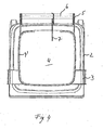
- Fig. 3 shows the lid assembly 1 in a perspective view obliquely from below.
- the cover assembly 1 has a downwardly directed groove 9, in which a seal 10, preferably soft seal, extends from a suitable elastomer.
- the groove 9 is formed so that it can be placed on a container 2 upwardly extending edge and thus a seal of the lid assembly 1 relative to the interior of the container 2 is ensured.
- the groove 9 is cambered over its length sections, ie different deep, so that the seal 10 extends unevenly deep within the groove 9.
- the groove 9 in the region of the mounting bracket 3 and on the back in the region of the mounting arm 7 is formed to be less deep in order to increase the pressure forces on the seal 10 in these areas.
- a particularly good tightness of the cover assembly 1 can be achieved.
- the cover 4 on its underside reinforcing struts 11.
- the lid 4 does not deform under load and fits exactly on the provided on the container 2 edge.
- a plurality of reinforcing struts 11 are provided in a cross-over shape, but any other arbitrary pattern is possible as long as the lid 4 is sufficiently stiffened.
- Fig. 4 the lid assembly 1 of the invention is shown on a container 2 in a view from above. Here, it is easy to see how the mounting brackets 3 overlap the outer edge of the container 2 and engage with their hook-shaped free ends 3 'an edge of the container 2.
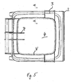
- Fig. 5 the lid assembly 1 of the invention is shown in a further embodiment in plan view.
- the lid 4 in this case has two arranged in the rear region of the mounting arms 7, which guide the lid 4 when opening and closing on the holding device 6 and support it at loads.
- the reinforcing rib 4 'extends over the entire circumference of the lid 4 and provides additional stabilization for the fastening arms 7.
- Fig. 6 is a sectional view taken along the line A - A in Fig. 5 ,
- the cover 4 in this case has a downwardly open groove 9, in the circumferential direction, a seal 10 extends.
- the groove 9 is formed by two downwardly directed webs 9 ', 9 "The outer web 9' has a length such that it securely engages over the upwardly protruding edge of the container 2, but at the same time to the upwardly directed outer edge of the container 2 is also spaced in the closed state of the lid 4.
- the inner web 9 is shown in the Extended design and forms the projecting into the container 2 skirt 8. In this way, contamination of the edge region is reliably prevented
- the skirt 8 is formed thin, that is, that it has a thickness of about 2-10 mm.
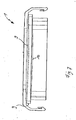
- Fig. 7 shows the lid assembly 1 in a side view.
- the circumferentially extending groove 9 is cambered in this embodiment at the respective longitudinal sides.
- the camber preferably has a height of 2-4 mm. In this way, a particularly good seal is achieved because the running in the groove 9 seal 10 is pressed firmly against the upstanding edge of the container 2.
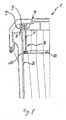
- Fig. 8 shows a sectional view of the lid assembly 1 according to another embodiment.
- the characteristics are essentially the same as those of the Fig. 6
- the webs 9 ', 9 "of the groove 9 are the same length
- the skirt 8 is arranged as an additional element in the interior of the lid 4 and spaced from the inner web 9".
- a circumferentially extending seal 12 preferably a rubber seal, is provided for sealing between the skirt 8 and the inner wall of the container 2.
- Such a seal can be plugged with a Einstecknut on the edge of the skirt and press with a laterally molded thereto sealing bead against the container wall.
- This front skirt portion may also be elastically movable and provided at the corners with a slot 8 '.
- this skirt part can be manually pressed in the Y-direction when opening the lid 4 and a secure concern in the closed state at the front inner wall of the container 2 can be ensured due to its elasticity.
- FIG. 9 how out Fig. 9 can be seen, the features as in connection with the embodiments of a lid in the Fig. 1 to 8 are described with particular advantage in a lid for a ball bottom container 20 used.
- a ball bottom container 20 is in an excellent manner for the absorption of hot fluids, since a strength of the container is ensured even with hot content materials due to the special structure that arises as a result of the combination square container top with ball bottom. This strength is further increased by the tension of the lid in the opening, so that a bulging of wall areas in equipped with lids globe bottom containers.
Landscapes
- Engineering & Computer Science (AREA)
- Mechanical Engineering (AREA)
- Closures For Containers (AREA)
Priority Applications (2)
| Application Number | Priority Date | Filing Date | Title |
|---|---|---|---|
| SI200830901T SI2036838T1 (sl) | 2007-09-14 | 2008-04-23 | Razporeditev pokrova za vsebnik za tekočine |
| PL08007860T PL2036838T3 (pl) | 2007-09-14 | 2008-04-23 | Zespół pokrywy pojemnika na ciecze |
Applications Claiming Priority (1)
| Application Number | Priority Date | Filing Date | Title |
|---|---|---|---|
| DE202007012923U DE202007012923U1 (de) | 2007-09-11 | 2007-09-14 | Deckelanordnung für einen Flüssigkeitsbehälter |
Publications (2)
| Publication Number | Publication Date |
|---|---|
| EP2036838A1 EP2036838A1 (de) | 2009-03-18 |
| EP2036838B1 true EP2036838B1 (de) | 2012-12-05 |
Family
ID=39884556
Family Applications (1)
| Application Number | Title | Priority Date | Filing Date |
|---|---|---|---|
| EP08007860A Active EP2036838B1 (de) | 2007-09-14 | 2008-04-23 | Deckelanordnung für einen Flüssigkeitsbehälter |
Country Status (8)
| Country | Link |
|---|---|
| US (1) | US8479949B2 (ru) |
| EP (1) | EP2036838B1 (ru) |
| KR (1) | KR20090027178A (ru) |
| AU (1) | AU2008212080B8 (ru) |
| ES (1) | ES2400820T3 (ru) |
| PL (1) | PL2036838T3 (ru) |
| RU (1) | RU2491218C2 (ru) |
| SI (1) | SI2036838T1 (ru) |
Families Citing this family (31)
| Publication number | Priority date | Publication date | Assignee | Title |
|---|---|---|---|---|
| KR100925547B1 (ko) * | 2009-04-06 | 2009-11-06 | (주)오토코리아 | 댐퍼가 구비된 쓰레기통 |
| KR100925542B1 (ko) * | 2009-04-06 | 2009-11-06 | (주)오토코리아 | 댐퍼가 구비된 쓰레기통 |
| KR101336827B1 (ko) * | 2012-07-24 | 2013-12-04 | 엔피씨(주) | 음식물 쓰레기통 |
| CA2838382A1 (en) | 2013-01-09 | 2014-07-09 | Speed Eco Products and Systems Ltd. | Container lid latch |
| US9726380B2 (en) * | 2013-07-10 | 2017-08-08 | Kenyon International, Inc. | Collapsible grill lid |
| US9258943B1 (en) * | 2013-08-06 | 2016-02-16 | John W. Ruger | Plant extraction assembly |
| US11806266B2 (en) | 2014-03-19 | 2023-11-07 | Purewick Corporation | Apparatus and methods for receiving discharged urine |
| US11376152B2 (en) | 2014-03-19 | 2022-07-05 | Purewick Corporation | Apparatus and methods for receiving discharged urine |
| US9821830B1 (en) * | 2016-05-23 | 2017-11-21 | Janelle Matlock | Covered wheelbarrow system |
| US10376406B2 (en) | 2016-07-27 | 2019-08-13 | Purewick Corporation | Male urine collection device using wicking material |
| US10973678B2 (en) | 2016-07-27 | 2021-04-13 | Purewick Corporation | Apparatus and methods for receiving discharged urine |
| US10900255B2 (en) | 2016-08-15 | 2021-01-26 | Fath, Inc. | Tamper resistant gravity latch |
| US10954063B2 (en) * | 2016-11-11 | 2021-03-23 | Rehrig Pacific Company | Roll out cart |
| USD839074S1 (en) | 2017-08-14 | 2019-01-29 | Fath, Inc. | Gravity latch |
| AU2019262944A1 (en) | 2018-05-01 | 2020-11-26 | Purewick Corporation | Fluid collection garments |
| BR112020022290A2 (pt) | 2018-05-01 | 2021-02-23 | Purewick Corporation | dispositivos de coleta de fluido, sistemas relacionados, e métodos relacionados |
| EP3787569A1 (en) | 2018-05-01 | 2021-03-10 | Purewick Corporation | Fluid collection devices, systems, and methods |
| US11084514B2 (en) * | 2018-10-16 | 2021-08-10 | Toolspace Pty Ltd | Semipermanent wheelbarrow enclosure |
| DE102019101724A1 (de) * | 2019-01-24 | 2020-07-30 | Sudhaus Gmbh | Abfallaufnahmevorrichtung |
| DE202019104264U1 (de) * | 2019-08-02 | 2020-11-03 | Sudhaus Gmbh | Abfallaufnahmevorrichtung |
| US12048643B2 (en) | 2020-05-27 | 2024-07-30 | Purewick Corporation | Fluid collection assemblies including at least one inflation device and methods and systems of using the same |
| USD967409S1 (en) | 2020-07-15 | 2022-10-18 | Purewick Corporation | Urine collection apparatus cover |
| US11801186B2 (en) | 2020-09-10 | 2023-10-31 | Purewick Corporation | Urine storage container handle and lid accessories |
| US12042423B2 (en) | 2020-10-07 | 2024-07-23 | Purewick Corporation | Fluid collection systems including at least one tensioning element |
| US12048644B2 (en) | 2020-11-03 | 2024-07-30 | Purewick Corporation | Apparatus for receiving discharged urine |
| US12070432B2 (en) | 2020-11-11 | 2024-08-27 | Purewick Corporation | Urine collection system including a flow meter and related methods |
| AU2022211357B2 (en) | 2021-01-19 | 2024-08-01 | Purewick Corporation | Variable fit fluid collection devices, systems, and methods |
| WO2022182385A1 (en) | 2021-02-26 | 2022-09-01 | Purewick Corporation | Fluid collection devices having a sump between a tube opening and a barrier, and related systems and methods |
| US11938054B2 (en) | 2021-03-10 | 2024-03-26 | Purewick Corporation | Bodily waste and fluid collection with sacral pad |
| US12029677B2 (en) | 2021-04-06 | 2024-07-09 | Purewick Corporation | Fluid collection devices having a collection bag, and related systems and methods |
| USD1027607S1 (en) | 2022-08-17 | 2024-05-21 | Fath, Inc. | Gravity latch |
Family Cites Families (18)
| Publication number | Priority date | Publication date | Assignee | Title |
|---|---|---|---|---|
| US3688942A (en) * | 1970-11-20 | 1972-09-05 | Continental Can Co | Container and closure combination |
| US3759415A (en) * | 1972-06-13 | 1973-09-18 | Nosco Plastics | Pail |
| US3999677A (en) * | 1975-06-30 | 1976-12-28 | Van Dorn Company | Plastic lid for containers |
| IT1204261B (it) * | 1986-01-24 | 1989-03-01 | Olimpio Stocchiero | Coperchio per accumulatori chiuso a pressione sul contenitore |
| US4691840A (en) * | 1986-11-12 | 1987-09-08 | Gott Corporation | Lid locking handle for waste container |
| US5103994A (en) * | 1990-12-28 | 1992-04-14 | Rubbermaid Incorporated | Locking system for a waste receptacle |
| US5230525A (en) * | 1991-06-25 | 1993-07-27 | Rubbermaid Commercial Products Inc. | Step-on waste container |
| US5207345A (en) * | 1992-07-10 | 1993-05-04 | Stewart Gene L | Lid adapter for bucket |
| US5323923A (en) * | 1992-08-17 | 1994-06-28 | Schauer Charles D | Waste container |
| US5385259A (en) * | 1994-01-28 | 1995-01-31 | Safety 1St, Inc. | Diaper pail |
| US5641090A (en) * | 1994-11-14 | 1997-06-24 | Rubbermaid Commercial Products Inc. | Lid for refuse a container |
| US5699929A (en) * | 1996-03-25 | 1997-12-23 | Ouno; Taiichi | Garbage container |
| FR2784364B1 (fr) * | 1998-10-13 | 2000-12-15 | Plastic Omnium Cie | Bac pour la collecte de dechets, equipe d'un transpondeur |
| US20030160057A1 (en) * | 2000-07-12 | 2003-08-28 | Wiggo-Arne Johansen | Blocking device for a waste container lid |
| ES1048353Y (es) | 2001-02-15 | 2001-12-01 | Contenur Espana Sl | Cubo contenedor para recogida selectiva de residuos liquidos. |
| CA2372465A1 (en) * | 2002-02-15 | 2003-08-15 | Norseman Plastics Limited | Refuse container |
| DE20304131U1 (de) | 2003-03-13 | 2003-06-05 | Häfner & Krullmann GmbH, 33818 Leopoldshöhe | Behälter zum Sammeln von Abfall |
| DE202007012923U1 (de) * | 2007-09-11 | 2008-03-27 | P. Henkel Gmbh | Deckelanordnung für einen Flüssigkeitsbehälter |
-
2008
- 2008-04-23 PL PL08007860T patent/PL2036838T3/pl unknown
- 2008-04-23 EP EP08007860A patent/EP2036838B1/de active Active
- 2008-04-23 ES ES08007860T patent/ES2400820T3/es active Active
- 2008-04-23 SI SI200830901T patent/SI2036838T1/sl unknown
- 2008-09-09 AU AU2008212080A patent/AU2008212080B8/en active Active
- 2008-09-09 US US12/283,065 patent/US8479949B2/en active Active
- 2008-09-10 RU RU2008136535/12A patent/RU2491218C2/ru active
- 2008-09-11 KR KR1020080089882A patent/KR20090027178A/ko not_active Application Discontinuation
Also Published As
| Publication number | Publication date |
|---|---|
| SI2036838T1 (sl) | 2013-04-30 |
| ES2400820T3 (es) | 2013-04-12 |
| AU2008212080B2 (en) | 2013-11-07 |
| KR20090027178A (ko) | 2009-03-16 |
| AU2008212080A1 (en) | 2009-03-26 |
| RU2491218C2 (ru) | 2013-08-27 |
| US8479949B2 (en) | 2013-07-09 |
| US20090134164A1 (en) | 2009-05-28 |
| PL2036838T3 (pl) | 2013-05-31 |
| AU2008212080A8 (en) | 2014-02-27 |
| AU2008212080B8 (en) | 2014-02-27 |
| EP2036838A1 (de) | 2009-03-18 |
| RU2008136535A (ru) | 2010-03-20 |
Similar Documents
| Publication | Publication Date | Title |
|---|---|---|
| EP2036838B1 (de) | Deckelanordnung für einen Flüssigkeitsbehälter | |
| AT401767B (de) | Müllbehälter | |
| AT507950B1 (de) | Deckel eines behälters | |
| DE68917789T2 (de) | Deckel mit regelbarer Ausgiesstülle und Belüftungseinrichtung. | |
| DE4143145A1 (de) | Verrigelungssystem fuer einen abfallbehaelter | |
| EP1343703A1 (de) | Palettencontainer | |
| EP0881161A1 (de) | Transport- und Lagerbehälter für Flüssigkeiten | |
| DE202010005089U1 (de) | Sterilcontainer für medizinische Zwecke | |
| DE202007012923U1 (de) | Deckelanordnung für einen Flüssigkeitsbehälter | |
| EP3552983B1 (de) | Gebinde mit einem sicherungsring zur transportsicherung eines deckels | |
| WO2021156144A1 (de) | Behälter mit fixierring für den transport und die lagerung von flüssigkeiten | |
| EP3377416A1 (de) | Behälter aus kunststoff | |
| DE2725215A1 (de) | Verschluss | |
| CH690272A5 (de) | Aufsatzteil für Kehrichtbehälter, insbesondere für im Haushalt verwendete Kehrichtbehälter. | |
| EP3655340A1 (de) | Behälter | |
| DE4229604C2 (de) | Siegelkappe für einen Sicherheitsverschluß | |
| WO1988000915A1 (en) | Collection tank for reusable product | |
| DE202020106218U1 (de) | Sicherungsring zur Transportsicherung eines Deckels, Deckel und Gebinde | |
| DE3104604A1 (de) | Dosenverschluss | |
| DE9320240U1 (de) | Kunststoffbehälter | |
| DE4439821C2 (de) | Kraftwagentürfeststeller | |
| DE9403247U1 (de) | Transportbehälter | |
| DE4422936A1 (de) | Behälter | |
| DE20304131U1 (de) | Behälter zum Sammeln von Abfall | |
| DE202017100341U1 (de) | Behälter |
Legal Events
| Date | Code | Title | Description |
|---|---|---|---|
| PUAI | Public reference made under article 153(3) epc to a published international application that has entered the european phase |
Free format text: ORIGINAL CODE: 0009012 |
|
| 17P | Request for examination filed |
Effective date: 20080710 |
|
| AK | Designated contracting states |
Kind code of ref document: A1 Designated state(s): AT BE BG CH CY CZ DE DK EE ES FI FR GB GR HR HU IE IS IT LI LT LU LV MC MT NL NO PL PT RO SE SI SK TR |
|
| AX | Request for extension of the european patent |
Extension state: AL BA MK RS |
|
| AKX | Designation fees paid |
Designated state(s): AT BE BG CH CY CZ DE DK EE ES FI FR GB GR HR HU IE IS IT LI LT LU LV MC MT NL NO PL PT RO SE SI SK TR |
|
| 17Q | First examination report despatched |
Effective date: 20091216 |
|
| GRAP | Despatch of communication of intention to grant a patent |
Free format text: ORIGINAL CODE: EPIDOSNIGR1 |
|
| GRAS | Grant fee paid |
Free format text: ORIGINAL CODE: EPIDOSNIGR3 |
|
| GRAA | (expected) grant |
Free format text: ORIGINAL CODE: 0009210 |
|
| AK | Designated contracting states |
Kind code of ref document: B1 Designated state(s): AT BE BG CH CY CZ DE DK EE ES FI FR GB GR HR HU IE IS IT LI LT LU LV MC MT NL NO PL PT RO SE SI SK TR |
|
| REG | Reference to a national code |
Ref country code: GB Ref legal event code: FG4D Free format text: NOT ENGLISH |
|
| REG | Reference to a national code |
Ref country code: CH Ref legal event code: EP |
|
| REG | Reference to a national code |
Ref country code: AT Ref legal event code: REF Ref document number: 587161 Country of ref document: AT Kind code of ref document: T Effective date: 20121215 |
|
| REG | Reference to a national code |
Ref country code: IE Ref legal event code: FG4D Free format text: LANGUAGE OF EP DOCUMENT: GERMAN |
|
| REG | Reference to a national code |
Ref country code: DE Ref legal event code: R096 Ref document number: 502008008805 Country of ref document: DE Effective date: 20130131 |
|
| REG | Reference to a national code |
Ref country code: SE Ref legal event code: TRGR |
|
| REG | Reference to a national code |
Ref country code: ES Ref legal event code: FG2A Ref document number: 2400820 Country of ref document: ES Kind code of ref document: T3 Effective date: 20130412 |
|
| PG25 | Lapsed in a contracting state [announced via postgrant information from national office to epo] |
Ref country code: FI Free format text: LAPSE BECAUSE OF FAILURE TO SUBMIT A TRANSLATION OF THE DESCRIPTION OR TO PAY THE FEE WITHIN THE PRESCRIBED TIME-LIMIT Effective date: 20121205 Ref country code: NO Free format text: LAPSE BECAUSE OF FAILURE TO SUBMIT A TRANSLATION OF THE DESCRIPTION OR TO PAY THE FEE WITHIN THE PRESCRIBED TIME-LIMIT Effective date: 20130305 Ref country code: LT Free format text: LAPSE BECAUSE OF FAILURE TO SUBMIT A TRANSLATION OF THE DESCRIPTION OR TO PAY THE FEE WITHIN THE PRESCRIBED TIME-LIMIT Effective date: 20121205 |
|
| REG | Reference to a national code |
Ref country code: NL Ref legal event code: VDEP Effective date: 20121205 |
|
| REG | Reference to a national code |
Ref country code: SK Ref legal event code: T3 Ref document number: E 13535 Country of ref document: SK |
|
| REG | Reference to a national code |
Ref country code: LT Ref legal event code: MG4D |
|
| PG25 | Lapsed in a contracting state [announced via postgrant information from national office to epo] |
Ref country code: LV Free format text: LAPSE BECAUSE OF FAILURE TO SUBMIT A TRANSLATION OF THE DESCRIPTION OR TO PAY THE FEE WITHIN THE PRESCRIBED TIME-LIMIT Effective date: 20121205 Ref country code: GR Free format text: LAPSE BECAUSE OF FAILURE TO SUBMIT A TRANSLATION OF THE DESCRIPTION OR TO PAY THE FEE WITHIN THE PRESCRIBED TIME-LIMIT Effective date: 20130306 |
|
| REG | Reference to a national code |
Ref country code: PL Ref legal event code: T3 |
|
| PG25 | Lapsed in a contracting state [announced via postgrant information from national office to epo] |
Ref country code: IS Free format text: LAPSE BECAUSE OF FAILURE TO SUBMIT A TRANSLATION OF THE DESCRIPTION OR TO PAY THE FEE WITHIN THE PRESCRIBED TIME-LIMIT Effective date: 20130405 Ref country code: BG Free format text: LAPSE BECAUSE OF FAILURE TO SUBMIT A TRANSLATION OF THE DESCRIPTION OR TO PAY THE FEE WITHIN THE PRESCRIBED TIME-LIMIT Effective date: 20130305 Ref country code: EE Free format text: LAPSE BECAUSE OF FAILURE TO SUBMIT A TRANSLATION OF THE DESCRIPTION OR TO PAY THE FEE WITHIN THE PRESCRIBED TIME-LIMIT Effective date: 20121205 |
|
| PG25 | Lapsed in a contracting state [announced via postgrant information from national office to epo] |
Ref country code: PT Free format text: LAPSE BECAUSE OF FAILURE TO SUBMIT A TRANSLATION OF THE DESCRIPTION OR TO PAY THE FEE WITHIN THE PRESCRIBED TIME-LIMIT Effective date: 20130405 Ref country code: RO Free format text: LAPSE BECAUSE OF FAILURE TO SUBMIT A TRANSLATION OF THE DESCRIPTION OR TO PAY THE FEE WITHIN THE PRESCRIBED TIME-LIMIT Effective date: 20121205 |
|
| PLBE | No opposition filed within time limit |
Free format text: ORIGINAL CODE: 0009261 |
|
| STAA | Information on the status of an ep patent application or granted ep patent |
Free format text: STATUS: NO OPPOSITION FILED WITHIN TIME LIMIT |
|
| PG25 | Lapsed in a contracting state [announced via postgrant information from national office to epo] |
Ref country code: DK Free format text: LAPSE BECAUSE OF FAILURE TO SUBMIT A TRANSLATION OF THE DESCRIPTION OR TO PAY THE FEE WITHIN THE PRESCRIBED TIME-LIMIT Effective date: 20121205 |
|
| 26N | No opposition filed |
Effective date: 20130906 |
|
| PG25 | Lapsed in a contracting state [announced via postgrant information from national office to epo] |
Ref country code: CY Free format text: LAPSE BECAUSE OF FAILURE TO SUBMIT A TRANSLATION OF THE DESCRIPTION OR TO PAY THE FEE WITHIN THE PRESCRIBED TIME-LIMIT Effective date: 20121205 Ref country code: HR Free format text: LAPSE BECAUSE OF FAILURE TO SUBMIT A TRANSLATION OF THE DESCRIPTION OR TO PAY THE FEE WITHIN THE PRESCRIBED TIME-LIMIT Effective date: 20121205 Ref country code: MC Free format text: LAPSE BECAUSE OF FAILURE TO SUBMIT A TRANSLATION OF THE DESCRIPTION OR TO PAY THE FEE WITHIN THE PRESCRIBED TIME-LIMIT Effective date: 20121205 |
|
| REG | Reference to a national code |
Ref country code: DE Ref legal event code: R097 Ref document number: 502008008805 Country of ref document: DE Effective date: 20130906 |
|
| REG | Reference to a national code |
Ref country code: NL Ref legal event code: RD1H Effective date: 20140513 |
|
| REG | Reference to a national code |
Ref country code: NL Ref legal event code: RDX Effective date: 20140617 Ref country code: NL Ref legal event code: RD1H Effective date: 20140513 |
|
| REG | Reference to a national code |
Ref country code: NL Ref legal event code: BK Free format text: TEN ONTERECHTE VERVALLENOP 2012.12.05 PUBLIKATIE I.E. 2013/18UITGEGEVEN 2013.05.01 |
|
| PG25 | Lapsed in a contracting state [announced via postgrant information from national office to epo] |
Ref country code: MT Free format text: LAPSE BECAUSE OF FAILURE TO SUBMIT A TRANSLATION OF THE DESCRIPTION OR TO PAY THE FEE WITHIN THE PRESCRIBED TIME-LIMIT Effective date: 20121205 |
|
| PG25 | Lapsed in a contracting state [announced via postgrant information from national office to epo] |
Ref country code: TR Free format text: LAPSE BECAUSE OF FAILURE TO SUBMIT A TRANSLATION OF THE DESCRIPTION OR TO PAY THE FEE WITHIN THE PRESCRIBED TIME-LIMIT Effective date: 20121205 |
|
| PG25 | Lapsed in a contracting state [announced via postgrant information from national office to epo] |
Ref country code: LU Free format text: LAPSE BECAUSE OF NON-PAYMENT OF DUE FEES Effective date: 20130423 Ref country code: HU Free format text: LAPSE BECAUSE OF FAILURE TO SUBMIT A TRANSLATION OF THE DESCRIPTION OR TO PAY THE FEE WITHIN THE PRESCRIBED TIME-LIMIT; INVALID AB INITIO Effective date: 20080423 |
|
| REG | Reference to a national code |
Ref country code: NL Ref legal event code: RD2H Effective date: 20140704 |
|
| REG | Reference to a national code |
Ref country code: FR Ref legal event code: PLFP Year of fee payment: 9 |
|
| REG | Reference to a national code |
Ref country code: FR Ref legal event code: PLFP Year of fee payment: 10 |
|
| REG | Reference to a national code |
Ref country code: FR Ref legal event code: PLFP Year of fee payment: 11 |
|
| PGFP | Annual fee paid to national office [announced via postgrant information from national office to epo] |
Ref country code: NL Payment date: 20240418 Year of fee payment: 17 |
|
| PGFP | Annual fee paid to national office [announced via postgrant information from national office to epo] |
Ref country code: PL Payment date: 20240320 Year of fee payment: 17 |
|
| PGFP | Annual fee paid to national office [announced via postgrant information from national office to epo] |
Ref country code: IE Payment date: 20240419 Year of fee payment: 17 |
|
| PGFP | Annual fee paid to national office [announced via postgrant information from national office to epo] |
Ref country code: GB Payment date: 20240418 Year of fee payment: 17 |
|
| PGFP | Annual fee paid to national office [announced via postgrant information from national office to epo] |
Ref country code: DE Payment date: 20240624 Year of fee payment: 17 |
|
| PGFP | Annual fee paid to national office [announced via postgrant information from national office to epo] |
Ref country code: CH Payment date: 20240501 Year of fee payment: 17 |
|
| PGFP | Annual fee paid to national office [announced via postgrant information from national office to epo] |
Ref country code: ES Payment date: 20240524 Year of fee payment: 17 |
|
| PGFP | Annual fee paid to national office [announced via postgrant information from national office to epo] |
Ref country code: CZ Payment date: 20240412 Year of fee payment: 17 Ref country code: AT Payment date: 20240419 Year of fee payment: 17 |
|
| PGFP | Annual fee paid to national office [announced via postgrant information from national office to epo] |
Ref country code: SK Payment date: 20240417 Year of fee payment: 17 |
|
| PGFP | Annual fee paid to national office [announced via postgrant information from national office to epo] |
Ref country code: IT Payment date: 20240424 Year of fee payment: 17 Ref country code: FR Payment date: 20240426 Year of fee payment: 17 Ref country code: SI Payment date: 20240411 Year of fee payment: 17 |
|
| PGFP | Annual fee paid to national office [announced via postgrant information from national office to epo] |
Ref country code: SE Payment date: 20240418 Year of fee payment: 17 Ref country code: BE Payment date: 20240418 Year of fee payment: 17 |