EP2036813A1 - Structure de fondation ainsi que son procédé de fabrication - Google Patents
Structure de fondation ainsi que son procédé de fabrication Download PDFInfo
- Publication number
- EP2036813A1 EP2036813A1 EP07017879A EP07017879A EP2036813A1 EP 2036813 A1 EP2036813 A1 EP 2036813A1 EP 07017879 A EP07017879 A EP 07017879A EP 07017879 A EP07017879 A EP 07017879A EP 2036813 A1 EP2036813 A1 EP 2036813A1
- Authority
- EP
- European Patent Office
- Prior art keywords
- foundation
- pile
- foundation structure
- piles
- sleeves
- Prior art date
- Legal status (The legal status is an assumption and is not a legal conclusion. Google has not performed a legal analysis and makes no representation as to the accuracy of the status listed.)
- Granted
Links
Images


Classifications
-
- B—PERFORMING OPERATIONS; TRANSPORTING
- B63—SHIPS OR OTHER WATERBORNE VESSELS; RELATED EQUIPMENT
- B63B—SHIPS OR OTHER WATERBORNE VESSELS; EQUIPMENT FOR SHIPPING
- B63B35/00—Vessels or similar floating structures specially adapted for specific purposes and not otherwise provided for
- B63B35/003—Vessels or similar floating structures specially adapted for specific purposes and not otherwise provided for for transporting very large loads, e.g. offshore structure modules
-
- B—PERFORMING OPERATIONS; TRANSPORTING
- B63—SHIPS OR OTHER WATERBORNE VESSELS; RELATED EQUIPMENT
- B63B—SHIPS OR OTHER WATERBORNE VESSELS; EQUIPMENT FOR SHIPPING
- B63B77/00—Transporting or installing offshore structures on site using buoyancy forces, e.g. using semi-submersible barges, ballasting the structure or transporting of oil-and-gas platforms
- B63B77/10—Transporting or installing offshore structures on site using buoyancy forces, e.g. using semi-submersible barges, ballasting the structure or transporting of oil-and-gas platforms specially adapted for electric power plants, e.g. wind turbines or tidal turbine generators
-
- E—FIXED CONSTRUCTIONS
- E02—HYDRAULIC ENGINEERING; FOUNDATIONS; SOIL SHIFTING
- E02B—HYDRAULIC ENGINEERING
- E02B17/00—Artificial islands mounted on piles or like supports, e.g. platforms on raisable legs or offshore constructions; Construction methods therefor
-
- E—FIXED CONSTRUCTIONS
- E02—HYDRAULIC ENGINEERING; FOUNDATIONS; SOIL SHIFTING
- E02B—HYDRAULIC ENGINEERING
- E02B17/00—Artificial islands mounted on piles or like supports, e.g. platforms on raisable legs or offshore constructions; Construction methods therefor
- E02B2017/0039—Methods for placing the offshore structure
-
- E—FIXED CONSTRUCTIONS
- E02—HYDRAULIC ENGINEERING; FOUNDATIONS; SOIL SHIFTING
- E02B—HYDRAULIC ENGINEERING
- E02B17/00—Artificial islands mounted on piles or like supports, e.g. platforms on raisable legs or offshore constructions; Construction methods therefor
- E02B2017/0056—Platforms with supporting legs
- E02B2017/0065—Monopile structures
-
- E—FIXED CONSTRUCTIONS
- E02—HYDRAULIC ENGINEERING; FOUNDATIONS; SOIL SHIFTING
- E02B—HYDRAULIC ENGINEERING
- E02B17/00—Artificial islands mounted on piles or like supports, e.g. platforms on raisable legs or offshore constructions; Construction methods therefor
- E02B2017/0091—Offshore structures for wind turbines
Definitions
- the invention relates to a method for installing a foundation structure for an offshore installation according to the preamble of claim 1 and a foundation structure according to the preamble of claim 6.
- the transport of offshore structures usually takes place with the aid of ships or pontoons on which the offshore structures rest.
- the Offshote structures are taken down from the ship or pontoon with the aid of suitable lifting devices and deposited on the seabed.
- the foundation structures and the foundation piles, the so-called piles are transported separately to the founding site and installed there.
- the foundation piles must be picked up by means of a lifting device at the founding of the transport and pivoted in the vertical.
- Object of the present invention is to provide a method and a foundation structure, whereby an installation of the foundation structure, especially your foundation piles, simple, fast, inexpensive and safe feasible.
- the object is achieved by a method having the features of claim 1.
- foundation piles on the foundation structure, for example, on land or in a dry dock.
- foundation structure and one or more foundation piles are transported as a unit.
- the terms "foundation pile” or “foundation piles” are used. In both cases, this should include the possibilities of using one or more foundation piles for a foundation structure.
- An advantage of the method according to the invention is that the foundation structure and the foundation piles are pre-assembled into a unit in which they have a predefined position to each other. This unit is transported as a whole to the founding site and lowered there as a unit, namely with the pre-assembled foundation piles. This eliminates a multiple picking up the individual foundation piles by a heavy-duty crane and the erection of the foundation piles in the vertical. In addition, the foundation piles require no additional transport area. In addition, the risky use of divers for threading the foundation piles in the pile sleeves of the foundation structure underwater can be dispensed with.
- the foundation piles are lowered together with the foundation structure.
- the foundation pile is inserted into a pile sleeve arranged on the foundation structure. This is done so that the lower ends of the foundation piles do not protrude downwardly from the pile sleeves, thereby not disturbing when the foundation structure is floated with the pre-assembled foundation piles to the foundation site.
- the foundation piles When transporting foundation structure and foundation piles, the foundation piles are preferably transported vertically or slightly inclined to the vertical. Slightly inclined means, for example, at an angle of up to 20 °, possibly even up to 30 °, inclined to the vertical. The angle is preferably to be chosen such that the foundation piles inserted into the pile sleeves of the foundation structure do not slide out of the pile sleeves during transport.
- the lowering of the foundation structure is carried out in an advantageous embodiment of the method by means of at least one buoyant body which is detachably coupled to the foundation structure, so that the foundation structure is attached to the at least one buoyancy body with the pre-assembled foundation piles.
- a plurality of buoyancy bodies are mounted on the foundation structure in order to initially give sufficient buoyancy to the submerged unit of foundation structure and foundation piles.
- the buoyant bodies are removed from the foundation structure and steered so that they get back to the water surface.
- the Lenzen happens for example via bilge pumps or pumps that pump air into the buoyancy.
- the buoyancy bodies are advantageously made robust, for example made of steel, and are suitable for multiple use.
- this is provided with a container or at least one chamber which can also flood and / or distend. If the foundation structure has a central tube, then this is provided, for example, with at least one chamber.
- a partial or complete flooding and / or leveling of the container or the central tube processes such as lowering, swimming or floating the foundation structure with the foundation piles can be supported and also controlled.
- the object of the invention is also achieved by a foundation structure with at least one pile sleeve surrounding a foundation pile, which is characterized in that the pile sleeves have means for holding the foundation piles.
- the fixation of the foundation structure on the seabed is done by the foundation piles are introduced into the seabed, for example, be rammed with the aid of a ram in the seabed.
- the means for holding preferably comprises a pile lock which prevents displacement of the foundation pile in the longitudinal direction of the receiving pile sleeve. This prevents slippage of the foundation pile through the pile sleeve, both during transport and during lowering of the foundation structure.
- the pile lock is formed as an inner constriction in a lower end region of the respective pile sleeve. It can also be provided more constrictions.
- the pile lock may include in addition to the inner constriction also other locking mechanisms. On the stake barrier or other locking mechanism rests a base at the bottom of each foundation pile.
- the means for holding by pressure and / or impact action are completely or partially destructible. In this way, the means for holding, after being of use during transport and during lowering of the foundation structure, does not constitute an obstacle to ramming or placing the foundation pile in a ground.
- head holders are provided for holding upper end portions of the foundation piles.
- the head mounts prevent tipping of the foundation piles, especially during transport to the foundation site and / or when lowering at the foundation site.
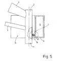
- the pile sleeve 2 and the buoyant body 6 are detachably connected to each other via a pair of coupling means 7, 16.
- the two in the Fig. 6 Coupling means 7 and 16 shown are arranged corresponding to each other so that they form a releasable latching connection between the pile sleeve 2 and the respective buoyant body 6.
- coupling means 7 and 16 are formed as a form-fitting interlocking semicircular Ringpratzen.
- each coupling means 7 and 16 have a projection with a (seen from above) semicircular course, which produce by intermeshing the positive but releasable connection between the respective pile sleeve 2 and the corresponding buoyant body 6, when the respective buoyancy body 6 relative to the pile sleeve 2 moves up or the pile sleeve 2 is lowered relative to the buoyancy body 6. Conversely, the positive connection of the coupling means 7 and 16 is released when the buoyant body 6 is moved relative to the pile sleeve 2 down or the foundation structure 1 is raised with the respective pile sleeve 2 relative to the buoyant body 6.
- the coupling means 7 is fixedly connected to the outside of the pile sleeve 2 by surrounding a non-sided half of the pile sleeve 2 in a semicircular manner.
- the coupling means 16 is connected to the buoyant body 6, with the semicircular inside of the U-shaped recess 14 in the buoyancy body. 6
- the corresponding projections of the coupling means 7, 16 are provided with chamfers, which allows small tolerances with respect to the position of the projections to each other in appending pile sleeves 2 of the foundation structure 1 to the buoyancy body 6.
- the chamfers of the coupling means 7, 16 serve to allow a movement between the respective pile sleeve 2 and the buoyant body 6 during engagement so that the foundation structure 1 and the buoyancy bodies 6 reach each other in a correct position.
- Fig. 7 shows a longitudinal section through one of the pile sleeves 2 of the foundation structure 1 with a mounted foundation pile 4, only a lower end portion 11 thereof.
- Each pile sleeve 2 has a means for holding the foundation pile 4.
- the means is designed as a pile lock 8.
- the pile lock 8 is formed by a ring which is temporarily fixed at the lower end of the respective pile sleeve 2, namely for holding the preassembled foundation pile 4 until after lowering the foundation structure 1 on the seabed 10, for example by welding.
- the annular pile lock 8 constricts the opening at the lower end of the pile sleeve 2 so far that a standing surface for a lower end face 13 of the pile sleeve 12 is formed, whereupon the preassembled pile sleeve 2 during the transport of the foundation structure 1 to the place of foundation and to lower the foundation structure 1 with the pile sleeves 2 rests.
- There are also other means for holding the lower end portion 11 of the foundation pile 4 in the respective pile sleeve 2 conceivable, for example, interrupted standing surface, spring tongues or Klemmh sleeves.
- the attachment of the pile locks 8 on the undersides of the pile sleeves 2 is made so that they reliably absorb the weight of each plug in the pile sleeves 2 foundation pile 4.
- the respective pile lock 8 is destroyed, in particular the connection of the same with the lower end of the respective pile sleeve 2, so that the foundation pile 4 when driving into the seabed 10 can slide through the pile sleeve 2.
- a foundation structure 1 with three pre-assembled foundation piles 4 is shown.
- the foundation piles 4 are inserted with their lower end portions in the pile sleeves 2, and indeed so far that the foundation piles 4 with their faces 13 on stake locks 8 at the bottom of the pile sleeves 2 stand up.
- the pile sleeves 2 are only connected during transport to the place of foundation at their upper end portions by head mounts, not shown, which stabilize the above from the pile sleeves 2 projecting foundation piles 4 during transport, especially against tipping.
- the foundation structure 1 with the three foundation piles 4 is attached to the three buoyancy bodies 6 for transport to the foundation site.
- Each buoyant body 6 is detachably coupled from the side to a pile sleeve 2 with the coupling means 7, 16.
- the coupling means 7, 16 are mounted at such a height on the buoyancy bodies 6 and the pile sleeves 2, that according to the illustration in the Fig. 5 the pile sleeves 2 project with a lower end portion 11 downwards against the buoyancy bodies 6.
- the measure to project the lower portions of the pile sleeve 2 relative to the undersides of the buoyancy bodies 6 is chosen so that the positive connection of the coupling means 7 and 16 between buoyancy bodies 6 and the pile sleeves 2 can be released by a downward movement of the buoyant body 6 on the pile sleeves 2 ,
- the attachment of the buoyancy bodies 6 to the foundation structure 1 takes place in such a way that the foundation structure 1 with the pile sleeves 2 and the foundation piles 4 inserted therein are lowered onto the water surface 9 until the pile sleeves 2 have something in place Dip water. Then the buoyancy bodies 6 already floating in the water are moved laterally from the outside to the pile sleeves 2, wherein the pile sleeves 2 engage in the U-shaped recesses 14 of the buoyancy bodies 6.
- a positive connection between the foundation means 7 and 16 is produced, thereby bringing about the detachable connections of the buoyancy bodies 6 with the pile sleeves 2 of the foundation structure 1.
- the foundation structure 1 with the preassembled foundation piles 4 hangs on the buoyancy bodies 6 located laterally next to the pile sleeves 2.
- the Fig. 8 shows the floating foundation structure 1 with pre-assembled foundation piles 4.
- the foundation structure 1 is suspended to the buoyancy bodies 6, which are coupled from the side to the pile sleeves 2 of the foundation structure 1, namely releasably.
- the foundation structure 1 can be transported with the foundation piles 4 floating to the foundation site, preferably by towing.
- the necessary buoyancy for floating transport receives the foundation structure 1 by the buoyancy body 6.
- These are for floating transport of the foundation structure 1 gelenzt, preferably completely.
- the chambers 15 of the buoyant body 6 therefore contain no water or at most residual amounts of water during transport of the foundation structure 1.
- buoyancy bodies 6 In heavy seas, it may be provided to partially flood the buoyant bodies 6, and only to such an extent that the foundation structure 1 with the buoyant bodies 6 can still be transported in a floating manner. As a result, the center of gravity of the hanging on the buoyancy bodies 6 founding structure 1 is lowered, which makes safer, especially in heavy seas, the floating transport hanging on the buoyancy bodies 6 foundation structure 1 with the foundation piles 4.
- the foundation structure 1 is lowered with the foundation piles 4 by an at least partial flooding of the chambers 15 of the buoyant bodies 6.
- the flooding occurs gradually, in a synchronous manner, so that the foundation structure 1 is lowered almost vertically.
- the vertical lowering of the foundation structure 1 can be assisted by a crane engaging at the top of the foundation structure 1 exerting an upward pulling force on the foundation structure 1, without, however, having to be able to control the weight of the entire foundation structure 1 including the foundation piles 4 to wear.
- the buoyant bodies 6 are flooded slowly and synchronously until the foundation structure 1 according to the Fig. 9 on the ground, in the illustrated embodiment, the seabed 10, rests, preferably with the lower end faces of the pile sleeves 2.
- the remain Floating body 6 is still coupled to the pile sleeves 2 until the foundation structure 1 has reached its intended position on the seabed 10. If necessary, the position can be corrected by partially letting the buoyancy bodies 6, whereby they raise the foundation structure 1 slightly again or put it in a kind of floating state in the water.
- FIG. 2 illustrates the uncoupling of the buoyancy bodies 6 from the pile sleeves 2 of the foundation structure 1.
- the buoyant bodies 6 are flooded so far, for example completely flooded, that they move downwards relative to the pile cores 2, for example so far as to almost reach resting on the seabed 10.
- the coupling means 16 on the buoyant bodies 6 are lowered relative to the coupling means 7 on the pile sleeves 2, thereby releasing the positive connection of the buoyancy bodies 6 with the pile sleeves 2 of the foundation structure 1.
- buoyant body 6 deduct from the pile sleeves 2 radially outward by the pile sleeves 2 are so to speak threaded out of the U-shaped recesses 14 in the buoyancy bodies 6.
- their chambers 15 are at least partially emptied of water.
- the buoyancy bodies 6 thereby reach the water surface 9, as a result of which the buoyancy bodies 6 are again available for a new use.
- the foundation structure 1 After the foundation structure 1 is lowered together with the foundation piles 4 stuck in the pile sleeves 2 onto the seabed 10, the foundation structure 1 is anchored at the foundation site by at least partially ramming the foundation piles 4 into the seabed 10. At the beginning of the ramming, the lower end surfaces 13 become the pile sleeves 2, the pile locks 8 on the undersides of the pile sleeves 2 separately. The foundation piles 4 can now slide through the pile sleeves 2 during further ramming.
- the pre-assembly according to the invention of the foundation piles 4 on the foundation structure 1 and the joint floating transport of the foundation structure 1 and the foundation piles 4 to the foundation site is not only suitable for the transport of the foundation structure 1 with buoyancy bodies 6 to the foundation site described above and shown in the figures. Rather, the invention can be used in any transport method of the foundation structure 1 with the foundation piles 4 to the foundation. The invention is therefore not limited to the transport of the foundation structure 1 with buoyancy bodies 6 to the foundation site. Rather, the Invention are also realized when the foundation structure 1 with the foundation piles 4 is transported in another way, for example, by ships, pontoons or on a floating crane, to the founding.
Landscapes
- Engineering & Computer Science (AREA)
- Mechanical Engineering (AREA)
- Chemical & Material Sciences (AREA)
- Ocean & Marine Engineering (AREA)
- Combustion & Propulsion (AREA)
- Transportation (AREA)
- Life Sciences & Earth Sciences (AREA)
- General Engineering & Computer Science (AREA)
- Sustainable Development (AREA)
- Sustainable Energy (AREA)
- Structural Engineering (AREA)
- Civil Engineering (AREA)
- Foundations (AREA)
- Joining Of Building Structures In Genera (AREA)
- Piles And Underground Anchors (AREA)
Priority Applications (3)
| Application Number | Priority Date | Filing Date | Title |
|---|---|---|---|
| EP07017879A EP2036813B1 (fr) | 2007-09-12 | 2007-09-12 | Structure de fondation ainsi que son procédé de fabrication |
| DE502007001992T DE502007001992D1 (de) | 2007-09-12 | 2007-09-12 | Gründungsstruktur sowie Verfahren zur Installation derselben |
| AT07017879T ATE448137T1 (de) | 2007-09-12 | 2007-09-12 | Gründungsstruktur sowie verfahren zur installation derselben |
Applications Claiming Priority (1)
| Application Number | Priority Date | Filing Date | Title |
|---|---|---|---|
| EP07017879A EP2036813B1 (fr) | 2007-09-12 | 2007-09-12 | Structure de fondation ainsi que son procédé de fabrication |
Publications (2)
| Publication Number | Publication Date |
|---|---|
| EP2036813A1 true EP2036813A1 (fr) | 2009-03-18 |
| EP2036813B1 EP2036813B1 (fr) | 2009-11-11 |
Family
ID=39149118
Family Applications (1)
| Application Number | Title | Priority Date | Filing Date |
|---|---|---|---|
| EP07017879A Not-in-force EP2036813B1 (fr) | 2007-09-12 | 2007-09-12 | Structure de fondation ainsi que son procédé de fabrication |
Country Status (3)
| Country | Link |
|---|---|
| EP (1) | EP2036813B1 (fr) |
| AT (1) | ATE448137T1 (fr) |
| DE (1) | DE502007001992D1 (fr) |
Cited By (6)
| Publication number | Priority date | Publication date | Assignee | Title |
|---|---|---|---|---|
| WO2011073627A3 (fr) * | 2009-12-18 | 2011-08-04 | Alstom Technology Ltd | Structure de fondation |
| DE102011102577B4 (de) * | 2011-05-25 | 2012-09-13 | Peter Kelemen | Schwimmvorrichtung und Verfahren zum Eindrücken eines Gegenstandes in einen Gewässerboden |
| CN102884316A (zh) * | 2010-04-18 | 2013-01-16 | 极地海洋研究所阿尔弗雷德-维格纳基金会 | 台架结构 |
| US20190249647A1 (en) * | 2016-09-09 | 2019-08-15 | Siemens Gamesa Renewable Energy A/S | Transition piece for a wind turbine |
| CN113906183A (zh) * | 2019-04-05 | 2022-01-07 | 埃斯特科股份公司 | 安装海上风力发电机塔架的方法 |
| EP3972895A4 (fr) * | 2019-05-21 | 2023-06-07 | AEgir Harvest AS | Structure flottante et son procédé d'installation |
Citations (9)
| Publication number | Priority date | Publication date | Assignee | Title |
|---|---|---|---|---|
| US3859804A (en) * | 1973-02-27 | 1975-01-14 | Brown & Root | Method and apparatus for transporting and launching an offshore tower |
| GB1446611A (en) * | 1973-02-15 | 1976-08-18 | British Petroleum Co | Pile guides |
| GB2204904A (en) * | 1987-04-28 | 1988-11-23 | Heerema Engineering | Level adjusting apparatus |
| GB2309246A (en) | 1996-01-17 | 1997-07-23 | Kvaerner Oil & Gas Ltd | Pile Sleeve Assembly |
| EP1101935A2 (fr) | 1999-11-17 | 2001-05-23 | Bonus Energy A/S | Navire et méthode d'installation des éoliennes en mer |
| DE20209000U1 (de) * | 2002-06-11 | 2003-04-17 | Kusan, Kristian, Dipl.-Ing., 56564 Neuwied | Windkraftanlage für den Offshorebereich |
| FR2849877A1 (fr) * | 2003-01-09 | 2004-07-16 | Saipem Sa | Procede d'installation en mer d'une eolienne |
| US20060051164A1 (en) * | 2004-09-07 | 2006-03-09 | Offshore Technology Development Pte Ltd | Jackup oil rig and similar platforms |
| GB2434341A (en) * | 2003-10-28 | 2007-07-25 | Delta Lifter Technologies As | A method and vessel for removing offshore structures |
-
2007
- 2007-09-12 DE DE502007001992T patent/DE502007001992D1/de active Active
- 2007-09-12 AT AT07017879T patent/ATE448137T1/de active
- 2007-09-12 EP EP07017879A patent/EP2036813B1/fr not_active Not-in-force
Patent Citations (9)
| Publication number | Priority date | Publication date | Assignee | Title |
|---|---|---|---|---|
| GB1446611A (en) * | 1973-02-15 | 1976-08-18 | British Petroleum Co | Pile guides |
| US3859804A (en) * | 1973-02-27 | 1975-01-14 | Brown & Root | Method and apparatus for transporting and launching an offshore tower |
| GB2204904A (en) * | 1987-04-28 | 1988-11-23 | Heerema Engineering | Level adjusting apparatus |
| GB2309246A (en) | 1996-01-17 | 1997-07-23 | Kvaerner Oil & Gas Ltd | Pile Sleeve Assembly |
| EP1101935A2 (fr) | 1999-11-17 | 2001-05-23 | Bonus Energy A/S | Navire et méthode d'installation des éoliennes en mer |
| DE20209000U1 (de) * | 2002-06-11 | 2003-04-17 | Kusan, Kristian, Dipl.-Ing., 56564 Neuwied | Windkraftanlage für den Offshorebereich |
| FR2849877A1 (fr) * | 2003-01-09 | 2004-07-16 | Saipem Sa | Procede d'installation en mer d'une eolienne |
| GB2434341A (en) * | 2003-10-28 | 2007-07-25 | Delta Lifter Technologies As | A method and vessel for removing offshore structures |
| US20060051164A1 (en) * | 2004-09-07 | 2006-03-09 | Offshore Technology Development Pte Ltd | Jackup oil rig and similar platforms |
Cited By (11)
| Publication number | Priority date | Publication date | Assignee | Title |
|---|---|---|---|---|
| WO2011073627A3 (fr) * | 2009-12-18 | 2011-08-04 | Alstom Technology Ltd | Structure de fondation |
| RU2555721C2 (ru) * | 2009-12-18 | 2015-07-10 | АЛЬСТОМ Риньюэбл Текнолоджиз | Фундаментальная конструкция |
| US9133597B2 (en) | 2009-12-18 | 2015-09-15 | Alstom Renewable Technologies | Foundation structure |
| CN102884316A (zh) * | 2010-04-18 | 2013-01-16 | 极地海洋研究所阿尔弗雷德-维格纳基金会 | 台架结构 |
| CN102884316B (zh) * | 2010-04-18 | 2015-08-19 | 极地海洋研究所赫尔姆霍茨中心阿尔弗雷德-维格纳基金会 | 台架结构 |
| US9151437B2 (en) | 2010-04-18 | 2015-10-06 | Alfred-Wegener-Institut Helmholtz-Zentrum Fuer Polar-Und Meeresforschung | Stand structure |
| DE102011102577B4 (de) * | 2011-05-25 | 2012-09-13 | Peter Kelemen | Schwimmvorrichtung und Verfahren zum Eindrücken eines Gegenstandes in einen Gewässerboden |
| US20190249647A1 (en) * | 2016-09-09 | 2019-08-15 | Siemens Gamesa Renewable Energy A/S | Transition piece for a wind turbine |
| US10767632B2 (en) * | 2016-09-09 | 2020-09-08 | Siemens Gamesa Renewable Energy A/S | Transition piece for a wind turbine |
| CN113906183A (zh) * | 2019-04-05 | 2022-01-07 | 埃斯特科股份公司 | 安装海上风力发电机塔架的方法 |
| EP3972895A4 (fr) * | 2019-05-21 | 2023-06-07 | AEgir Harvest AS | Structure flottante et son procédé d'installation |
Also Published As
| Publication number | Publication date |
|---|---|
| EP2036813B1 (fr) | 2009-11-11 |
| DE502007001992D1 (de) | 2009-12-24 |
| ATE448137T1 (de) | 2009-11-15 |
Similar Documents
| Publication | Publication Date | Title |
|---|---|---|
| DE10349109B4 (de) | Gründung für eine Offshore-Windenergieanlage | |
| EP2360373B1 (fr) | Installation offshore, fondation d'une installation offshore et procédé d'établissement d'une installation offshore | |
| EP1288122B1 (fr) | Support flottant pour une construction s'élevant au dessus de la surface de l'eau | |
| EP2236676B1 (fr) | Fondation d'une turbine d'énergie éolienne | |
| DE2345274A1 (de) | Hebbare hochseeplattform | |
| EP2036813B1 (fr) | Structure de fondation ainsi que son procédé de fabrication | |
| EP1876093A1 (fr) | Fondation offshore flottante et procédé de son réalisation | |
| EP2036815B1 (fr) | Procédé d'installation et de démontage d'une structure de fondation ainsi que structure de fondation et flotteur | |
| DE10101405A1 (de) | Off-Shore-Windkraftanlage | |
| DE2644725A1 (de) | Bohrinsel | |
| DE1506207A1 (de) | Schwimmfaehige Lagervorrichtung und Verfahren zu deren Betrieb | |
| DE1926001A1 (de) | Vorrichtung zum Herstellen einer Verbindung zwischen einem Unterwasser-Produktionsbohrlochkopf und einem darueber schwimmenden Fahrzeug | |
| DE2459478A1 (de) | Verfahren zur errichtung einer kuenstlichen insel | |
| DE20100588U1 (de) | Off-Shore-Windkraftanlage | |
| DE1947998A1 (de) | Verfahren und Vorrichtung zum Foerdern von OEl aus Unterwasserquellen | |
| EP3428345A1 (fr) | Fondation pour une éolienne en mer | |
| WO2016177783A1 (fr) | Ancre-poids flottante permettant d'ancrer une structure porteuse flottant en pleine mer à une éolienne, une station-service ou une station de conversion | |
| WO2018054532A1 (fr) | Ouvrage destiné à être érigé à la surface d'étendues d'eau et procédé pour son érection | |
| DE1956328A1 (de) | In einiger Entfernung von der Kueste versenkbare Vorrichtung zur Gewinnung und Lagerung von OEl | |
| DE3219968A1 (de) | Vorrichtung zum heben und entfernen des geruestes verbrauchter offshore-konstruktionen | |
| EP2623674A1 (fr) | Infrastructure pour une plateforme offshore et procédé d'installation d'une telle infrastructure | |
| DE2457536C3 (de) | Verfahren zum Transport und zum Absetzen einer Offshore-Plattform auf der Meeressohle sowie Offshore-Plattform | |
| EP3922845B1 (fr) | Ouvrage en mer flottant et son procédé d'installation | |
| DE102008017785A1 (de) | Fundament für ein Offshorebauwerk und Verfahren zum Erstellen eines Fundaments eines Offshorebauwerks | |
| EP2432984B1 (fr) | Chambre à houle destinée à une centrale houlomotrice et procédé de réalisation |
Legal Events
| Date | Code | Title | Description |
|---|---|---|---|
| GRAP | Despatch of communication of intention to grant a patent |
Free format text: ORIGINAL CODE: EPIDOSNIGR1 |
|
| PUAI | Public reference made under article 153(3) epc to a published international application that has entered the european phase |
Free format text: ORIGINAL CODE: 0009012 |
|
| GRAS | Grant fee paid |
Free format text: ORIGINAL CODE: EPIDOSNIGR3 |
|
| 17P | Request for examination filed |
Effective date: 20080428 |
|
| AK | Designated contracting states |
Kind code of ref document: A1 Designated state(s): AT BE BG CH CY CZ DE DK EE ES FI FR GB GR HU IE IS IT LI LT LU LV MC MT NL PL PT RO SE SI SK TR |
|
| AX | Request for extension of the european patent |
Extension state: AL BA HR MK RS |
|
| GRAA | (expected) grant |
Free format text: ORIGINAL CODE: 0009210 |
|
| AK | Designated contracting states |
Kind code of ref document: B1 Designated state(s): AT BE BG CH CY CZ DE DK EE ES FI FR GB GR HU IE IS IT LI LT LU LV MC MT NL PL PT RO SE SI SK TR |
|
| REG | Reference to a national code |
Ref country code: GB Ref legal event code: FG4D Free format text: NOT ENGLISH |
|
| REG | Reference to a national code |
Ref country code: CH Ref legal event code: EP |
|
| AKX | Designation fees paid |
Designated state(s): AT BE BG CH CY CZ DE DK EE ES FI FR GB GR HU IE IS IT LI LT LU LV MC MT NL PL PT RO SE SI SK TR |
|
| REG | Reference to a national code |
Ref country code: IE Ref legal event code: FG4D |
|
| REF | Corresponds to: |
Ref document number: 502007001992 Country of ref document: DE Date of ref document: 20091224 Kind code of ref document: P |
|
| LTIE | Lt: invalidation of european patent or patent extension |
Effective date: 20091111 |
|
| PG25 | Lapsed in a contracting state [announced via postgrant information from national office to epo] |
Ref country code: SE Free format text: LAPSE BECAUSE OF FAILURE TO SUBMIT A TRANSLATION OF THE DESCRIPTION OR TO PAY THE FEE WITHIN THE PRESCRIBED TIME-LIMIT Effective date: 20091111 Ref country code: ES Free format text: LAPSE BECAUSE OF FAILURE TO SUBMIT A TRANSLATION OF THE DESCRIPTION OR TO PAY THE FEE WITHIN THE PRESCRIBED TIME-LIMIT Effective date: 20100222 Ref country code: LT Free format text: LAPSE BECAUSE OF FAILURE TO SUBMIT A TRANSLATION OF THE DESCRIPTION OR TO PAY THE FEE WITHIN THE PRESCRIBED TIME-LIMIT Effective date: 20091111 Ref country code: PT Free format text: LAPSE BECAUSE OF FAILURE TO SUBMIT A TRANSLATION OF THE DESCRIPTION OR TO PAY THE FEE WITHIN THE PRESCRIBED TIME-LIMIT Effective date: 20100311 Ref country code: FI Free format text: LAPSE BECAUSE OF FAILURE TO SUBMIT A TRANSLATION OF THE DESCRIPTION OR TO PAY THE FEE WITHIN THE PRESCRIBED TIME-LIMIT Effective date: 20091111 Ref country code: IS Free format text: LAPSE BECAUSE OF FAILURE TO SUBMIT A TRANSLATION OF THE DESCRIPTION OR TO PAY THE FEE WITHIN THE PRESCRIBED TIME-LIMIT Effective date: 20100311 |
|
| PG25 | Lapsed in a contracting state [announced via postgrant information from national office to epo] |
Ref country code: SI Free format text: LAPSE BECAUSE OF FAILURE TO SUBMIT A TRANSLATION OF THE DESCRIPTION OR TO PAY THE FEE WITHIN THE PRESCRIBED TIME-LIMIT Effective date: 20091111 Ref country code: PL Free format text: LAPSE BECAUSE OF FAILURE TO SUBMIT A TRANSLATION OF THE DESCRIPTION OR TO PAY THE FEE WITHIN THE PRESCRIBED TIME-LIMIT Effective date: 20091111 Ref country code: LV Free format text: LAPSE BECAUSE OF FAILURE TO SUBMIT A TRANSLATION OF THE DESCRIPTION OR TO PAY THE FEE WITHIN THE PRESCRIBED TIME-LIMIT Effective date: 20091111 Ref country code: CY Free format text: LAPSE BECAUSE OF FAILURE TO SUBMIT A TRANSLATION OF THE DESCRIPTION OR TO PAY THE FEE WITHIN THE PRESCRIBED TIME-LIMIT Effective date: 20091111 |
|
| REG | Reference to a national code |
Ref country code: IE Ref legal event code: FD4D |
|
| PG25 | Lapsed in a contracting state [announced via postgrant information from national office to epo] |
Ref country code: RO Free format text: LAPSE BECAUSE OF FAILURE TO SUBMIT A TRANSLATION OF THE DESCRIPTION OR TO PAY THE FEE WITHIN THE PRESCRIBED TIME-LIMIT Effective date: 20091111 Ref country code: BG Free format text: LAPSE BECAUSE OF FAILURE TO SUBMIT A TRANSLATION OF THE DESCRIPTION OR TO PAY THE FEE WITHIN THE PRESCRIBED TIME-LIMIT Effective date: 20100211 Ref country code: IE Free format text: LAPSE BECAUSE OF FAILURE TO SUBMIT A TRANSLATION OF THE DESCRIPTION OR TO PAY THE FEE WITHIN THE PRESCRIBED TIME-LIMIT Effective date: 20091111 Ref country code: DK Free format text: LAPSE BECAUSE OF FAILURE TO SUBMIT A TRANSLATION OF THE DESCRIPTION OR TO PAY THE FEE WITHIN THE PRESCRIBED TIME-LIMIT Effective date: 20091111 Ref country code: EE Free format text: LAPSE BECAUSE OF FAILURE TO SUBMIT A TRANSLATION OF THE DESCRIPTION OR TO PAY THE FEE WITHIN THE PRESCRIBED TIME-LIMIT Effective date: 20091111 |
|
| PG25 | Lapsed in a contracting state [announced via postgrant information from national office to epo] |
Ref country code: CZ Free format text: LAPSE BECAUSE OF FAILURE TO SUBMIT A TRANSLATION OF THE DESCRIPTION OR TO PAY THE FEE WITHIN THE PRESCRIBED TIME-LIMIT Effective date: 20091111 Ref country code: SK Free format text: LAPSE BECAUSE OF FAILURE TO SUBMIT A TRANSLATION OF THE DESCRIPTION OR TO PAY THE FEE WITHIN THE PRESCRIBED TIME-LIMIT Effective date: 20091111 |
|
| PLBE | No opposition filed within time limit |
Free format text: ORIGINAL CODE: 0009261 |
|
| STAA | Information on the status of an ep patent application or granted ep patent |
Free format text: STATUS: NO OPPOSITION FILED WITHIN TIME LIMIT |
|
| 26N | No opposition filed |
Effective date: 20100812 |
|
| PG25 | Lapsed in a contracting state [announced via postgrant information from national office to epo] |
Ref country code: GR Free format text: LAPSE BECAUSE OF FAILURE TO SUBMIT A TRANSLATION OF THE DESCRIPTION OR TO PAY THE FEE WITHIN THE PRESCRIBED TIME-LIMIT Effective date: 20100212 |
|
| PG25 | Lapsed in a contracting state [announced via postgrant information from national office to epo] |
Ref country code: IT Free format text: LAPSE BECAUSE OF FAILURE TO SUBMIT A TRANSLATION OF THE DESCRIPTION OR TO PAY THE FEE WITHIN THE PRESCRIBED TIME-LIMIT Effective date: 20091111 |
|
| PG25 | Lapsed in a contracting state [announced via postgrant information from national office to epo] |
Ref country code: MC Free format text: LAPSE BECAUSE OF NON-PAYMENT OF DUE FEES Effective date: 20100930 |
|
| PG25 | Lapsed in a contracting state [announced via postgrant information from national office to epo] |
Ref country code: MT Free format text: LAPSE BECAUSE OF FAILURE TO SUBMIT A TRANSLATION OF THE DESCRIPTION OR TO PAY THE FEE WITHIN THE PRESCRIBED TIME-LIMIT Effective date: 20091111 |
|
| REG | Reference to a national code |
Ref country code: CH Ref legal event code: PL |
|
| PG25 | Lapsed in a contracting state [announced via postgrant information from national office to epo] |
Ref country code: CH Free format text: LAPSE BECAUSE OF NON-PAYMENT OF DUE FEES Effective date: 20110930 Ref country code: LI Free format text: LAPSE BECAUSE OF NON-PAYMENT OF DUE FEES Effective date: 20110930 |
|
| PG25 | Lapsed in a contracting state [announced via postgrant information from national office to epo] |
Ref country code: LU Free format text: LAPSE BECAUSE OF NON-PAYMENT OF DUE FEES Effective date: 20100912 Ref country code: HU Free format text: LAPSE BECAUSE OF FAILURE TO SUBMIT A TRANSLATION OF THE DESCRIPTION OR TO PAY THE FEE WITHIN THE PRESCRIBED TIME-LIMIT Effective date: 20100512 |
|
| PG25 | Lapsed in a contracting state [announced via postgrant information from national office to epo] |
Ref country code: TR Free format text: LAPSE BECAUSE OF FAILURE TO SUBMIT A TRANSLATION OF THE DESCRIPTION OR TO PAY THE FEE WITHIN THE PRESCRIBED TIME-LIMIT Effective date: 20091111 |
|
| PGFP | Annual fee paid to national office [announced via postgrant information from national office to epo] |
Ref country code: NL Payment date: 20130910 Year of fee payment: 7 Ref country code: DE Payment date: 20130926 Year of fee payment: 7 |
|
| REG | Reference to a national code |
Ref country code: AT Ref legal event code: MM01 Ref document number: 448137 Country of ref document: AT Kind code of ref document: T Effective date: 20120912 |
|
| PGFP | Annual fee paid to national office [announced via postgrant information from national office to epo] |
Ref country code: FR Payment date: 20130910 Year of fee payment: 7 Ref country code: GB Payment date: 20130911 Year of fee payment: 7 |
|
| PG25 | Lapsed in a contracting state [announced via postgrant information from national office to epo] |
Ref country code: AT Free format text: LAPSE BECAUSE OF NON-PAYMENT OF DUE FEES Effective date: 20120912 |
|
| PGFP | Annual fee paid to national office [announced via postgrant information from national office to epo] |
Ref country code: BE Payment date: 20130912 Year of fee payment: 7 |
|
| REG | Reference to a national code |
Ref country code: DE Ref legal event code: R119 Ref document number: 502007001992 Country of ref document: DE |
|
| GBPC | Gb: european patent ceased through non-payment of renewal fee |
Effective date: 20140912 |
|
| REG | Reference to a national code |
Ref country code: DE Ref legal event code: R119 Ref document number: 502007001992 Country of ref document: DE Effective date: 20150401 |
|
| REG | Reference to a national code |
Ref country code: FR Ref legal event code: ST Effective date: 20150529 |
|
| PG25 | Lapsed in a contracting state [announced via postgrant information from national office to epo] |
Ref country code: BE Free format text: LAPSE BECAUSE OF NON-PAYMENT OF DUE FEES Effective date: 20140930 Ref country code: NL Free format text: LAPSE BECAUSE OF NON-PAYMENT OF DUE FEES Effective date: 20150401 |
|
| PG25 | Lapsed in a contracting state [announced via postgrant information from national office to epo] |
Ref country code: DE Free format text: LAPSE BECAUSE OF NON-PAYMENT OF DUE FEES Effective date: 20150401 Ref country code: GB Free format text: LAPSE BECAUSE OF NON-PAYMENT OF DUE FEES Effective date: 20140912 |
|
| PG25 | Lapsed in a contracting state [announced via postgrant information from national office to epo] |
Ref country code: FR Free format text: LAPSE BECAUSE OF NON-PAYMENT OF DUE FEES Effective date: 20140930 |