EP2034576B1 - Bande adhésive destinée à l'enveloppement de marchandises longitudinales - Google Patents
Bande adhésive destinée à l'enveloppement de marchandises longitudinales Download PDFInfo
- Publication number
- EP2034576B1 EP2034576B1 EP08162060.1A EP08162060A EP2034576B1 EP 2034576 B1 EP2034576 B1 EP 2034576B1 EP 08162060 A EP08162060 A EP 08162060A EP 2034576 B1 EP2034576 B1 EP 2034576B1
- Authority
- EP
- European Patent Office
- Prior art keywords
- carrier
- adhesive
- adhesive tape
- adhesive layer
- layer
- Prior art date
- Legal status (The legal status is an assumption and is not a legal conclusion. Google has not performed a legal analysis and makes no representation as to the accuracy of the status listed.)
- Active
Links
- 239000000853 adhesive Substances 0.000 title claims description 32
- 230000001070 adhesive effect Effects 0.000 title claims description 31
- 239000002390 adhesive tape Substances 0.000 claims description 79
- 239000012790 adhesive layer Substances 0.000 claims description 33
- 239000010410 layer Substances 0.000 claims description 28
- 239000000463 material Substances 0.000 claims description 15
- XAGFODPZIPBFFR-UHFFFAOYSA-N aluminium Chemical compound [Al] XAGFODPZIPBFFR-UHFFFAOYSA-N 0.000 claims description 12
- 229910052782 aluminium Inorganic materials 0.000 claims description 12
- 239000002131 composite material Substances 0.000 claims description 12
- 239000004753 textile Substances 0.000 claims description 5
- NIXOWILDQLNWCW-UHFFFAOYSA-M Acrylate Chemical compound [O-]C(=O)C=C NIXOWILDQLNWCW-UHFFFAOYSA-M 0.000 claims description 4
- 239000012876 carrier material Substances 0.000 claims description 3
- 239000011888 foil Substances 0.000 claims description 3
- 239000002985 plastic film Substances 0.000 claims description 3
- 229920006255 plastic film Polymers 0.000 claims description 3
- 229920001971 elastomer Polymers 0.000 claims description 2
- 239000005060 rubber Substances 0.000 claims description 2
- 239000004411 aluminium Substances 0.000 claims 3
- 239000002759 woven fabric Substances 0.000 claims 1
- 238000005299 abrasion Methods 0.000 description 25
- 239000004744 fabric Substances 0.000 description 19
- 229920000139 polyethylene terephthalate Polymers 0.000 description 18
- 239000005020 polyethylene terephthalate Substances 0.000 description 18
- 239000010408 film Substances 0.000 description 14
- 239000006260 foam Substances 0.000 description 7
- 238000004519 manufacturing process Methods 0.000 description 7
- 239000000969 carrier Substances 0.000 description 6
- 230000001681 protective effect Effects 0.000 description 5
- 238000012360 testing method Methods 0.000 description 5
- 238000004804 winding Methods 0.000 description 5
- 239000011248 coating agent Substances 0.000 description 4
- 238000000576 coating method Methods 0.000 description 4
- 238000013461 design Methods 0.000 description 4
- 239000004820 Pressure-sensitive adhesive Substances 0.000 description 3
- 239000008186 active pharmaceutical agent Substances 0.000 description 3
- 238000010276 construction Methods 0.000 description 3
- 230000000694 effects Effects 0.000 description 3
- 238000009413 insulation Methods 0.000 description 3
- 229920002799 BoPET Polymers 0.000 description 2
- 239000004020 conductor Substances 0.000 description 2
- 239000004835 fabric adhesive Substances 0.000 description 2
- 238000012545 processing Methods 0.000 description 2
- 239000000126 substance Substances 0.000 description 2
- 239000004952 Polyamide Substances 0.000 description 1
- 150000001252 acrylic acid derivatives Chemical class 0.000 description 1
- 230000001154 acute effect Effects 0.000 description 1
- 238000005452 bending Methods 0.000 description 1
- 239000013039 cover film Substances 0.000 description 1
- 238000013016 damping Methods 0.000 description 1
- 230000001419 dependent effect Effects 0.000 description 1
- 238000011161 development Methods 0.000 description 1
- 238000010292 electrical insulation Methods 0.000 description 1
- 238000010438 heat treatment Methods 0.000 description 1
- 238000009434 installation Methods 0.000 description 1
- 239000011810 insulating material Substances 0.000 description 1
- 238000010030 laminating Methods 0.000 description 1
- 238000000034 method Methods 0.000 description 1
- 239000004745 nonwoven fabric Substances 0.000 description 1
- 229920002647 polyamide Polymers 0.000 description 1
- 229920006149 polyester-amide block copolymer Polymers 0.000 description 1
- -1 polyethylene terephthalate Polymers 0.000 description 1
- 239000011241 protective layer Substances 0.000 description 1
- 230000005855 radiation Effects 0.000 description 1
- 239000012812 sealant material Substances 0.000 description 1
- 239000002356 single layer Substances 0.000 description 1
- 229920003051 synthetic elastomer Polymers 0.000 description 1
- 239000005061 synthetic rubber Substances 0.000 description 1
- 238000010998 test method Methods 0.000 description 1
- 229920001187 thermosetting polymer Polymers 0.000 description 1
- 230000008719 thickening Effects 0.000 description 1
Images

Classifications
-
- C—CHEMISTRY; METALLURGY
- C09—DYES; PAINTS; POLISHES; NATURAL RESINS; ADHESIVES; COMPOSITIONS NOT OTHERWISE PROVIDED FOR; APPLICATIONS OF MATERIALS NOT OTHERWISE PROVIDED FOR
- C09J—ADHESIVES; NON-MECHANICAL ASPECTS OF ADHESIVE PROCESSES IN GENERAL; ADHESIVE PROCESSES NOT PROVIDED FOR ELSEWHERE; USE OF MATERIALS AS ADHESIVES
- C09J7/00—Adhesives in the form of films or foils
- C09J7/20—Adhesives in the form of films or foils characterised by their carriers
- C09J7/21—Paper; Textile fabrics
-
- C—CHEMISTRY; METALLURGY
- C09—DYES; PAINTS; POLISHES; NATURAL RESINS; ADHESIVES; COMPOSITIONS NOT OTHERWISE PROVIDED FOR; APPLICATIONS OF MATERIALS NOT OTHERWISE PROVIDED FOR
- C09J—ADHESIVES; NON-MECHANICAL ASPECTS OF ADHESIVE PROCESSES IN GENERAL; ADHESIVE PROCESSES NOT PROVIDED FOR ELSEWHERE; USE OF MATERIALS AS ADHESIVES
- C09J7/00—Adhesives in the form of films or foils
- C09J7/20—Adhesives in the form of films or foils characterised by their carriers
- C09J7/22—Plastics; Metallised plastics
-
- C—CHEMISTRY; METALLURGY
- C09—DYES; PAINTS; POLISHES; NATURAL RESINS; ADHESIVES; COMPOSITIONS NOT OTHERWISE PROVIDED FOR; APPLICATIONS OF MATERIALS NOT OTHERWISE PROVIDED FOR
- C09J—ADHESIVES; NON-MECHANICAL ASPECTS OF ADHESIVE PROCESSES IN GENERAL; ADHESIVE PROCESSES NOT PROVIDED FOR ELSEWHERE; USE OF MATERIALS AS ADHESIVES
- C09J2203/00—Applications of adhesives in processes or use of adhesives in the form of films or foils
- C09J2203/302—Applications of adhesives in processes or use of adhesives in the form of films or foils for bundling cables
-
- C—CHEMISTRY; METALLURGY
- C09—DYES; PAINTS; POLISHES; NATURAL RESINS; ADHESIVES; COMPOSITIONS NOT OTHERWISE PROVIDED FOR; APPLICATIONS OF MATERIALS NOT OTHERWISE PROVIDED FOR
- C09J—ADHESIVES; NON-MECHANICAL ASPECTS OF ADHESIVE PROCESSES IN GENERAL; ADHESIVE PROCESSES NOT PROVIDED FOR ELSEWHERE; USE OF MATERIALS AS ADHESIVES
- C09J2301/00—Additional features of adhesives in the form of films or foils
- C09J2301/20—Additional features of adhesives in the form of films or foils characterized by the structural features of the adhesive itself
- C09J2301/204—Additional features of adhesives in the form of films or foils characterized by the structural features of the adhesive itself the adhesive coating being discontinuous
-
- C—CHEMISTRY; METALLURGY
- C09—DYES; PAINTS; POLISHES; NATURAL RESINS; ADHESIVES; COMPOSITIONS NOT OTHERWISE PROVIDED FOR; APPLICATIONS OF MATERIALS NOT OTHERWISE PROVIDED FOR
- C09J—ADHESIVES; NON-MECHANICAL ASPECTS OF ADHESIVE PROCESSES IN GENERAL; ADHESIVE PROCESSES NOT PROVIDED FOR ELSEWHERE; USE OF MATERIALS AS ADHESIVES
- C09J2400/00—Presence of inorganic and organic materials
- C09J2400/20—Presence of organic materials
- C09J2400/26—Presence of textile or fabric
- C09J2400/263—Presence of textile or fabric in the substrate
-
- C—CHEMISTRY; METALLURGY
- C09—DYES; PAINTS; POLISHES; NATURAL RESINS; ADHESIVES; COMPOSITIONS NOT OTHERWISE PROVIDED FOR; APPLICATIONS OF MATERIALS NOT OTHERWISE PROVIDED FOR
- C09J—ADHESIVES; NON-MECHANICAL ASPECTS OF ADHESIVE PROCESSES IN GENERAL; ADHESIVE PROCESSES NOT PROVIDED FOR ELSEWHERE; USE OF MATERIALS AS ADHESIVES
- C09J2467/00—Presence of polyester
- C09J2467/006—Presence of polyester in the substrate
-
- C—CHEMISTRY; METALLURGY
- C09—DYES; PAINTS; POLISHES; NATURAL RESINS; ADHESIVES; COMPOSITIONS NOT OTHERWISE PROVIDED FOR; APPLICATIONS OF MATERIALS NOT OTHERWISE PROVIDED FOR
- C09J—ADHESIVES; NON-MECHANICAL ASPECTS OF ADHESIVE PROCESSES IN GENERAL; ADHESIVE PROCESSES NOT PROVIDED FOR ELSEWHERE; USE OF MATERIALS AS ADHESIVES
- C09J2477/00—Presence of polyamide
- C09J2477/006—Presence of polyamide in the substrate
-
- H—ELECTRICITY
- H02—GENERATION; CONVERSION OR DISTRIBUTION OF ELECTRIC POWER
- H02G—INSTALLATION OF ELECTRIC CABLES OR LINES, OR OF COMBINED OPTICAL AND ELECTRIC CABLES OR LINES
- H02G3/00—Installations of electric cables or lines or protective tubing therefor in or on buildings, equivalent structures or vehicles
- H02G3/02—Details
- H02G3/04—Protective tubing or conduits, e.g. cable ladders or cable troughs
- H02G3/0462—Tubings, i.e. having a closed section
- H02G3/0481—Tubings, i.e. having a closed section with a circular cross-section
Definitions
- the invention relates to an adhesive tape for the longitudinal sheathing of elongated goods, in particular a cable winding tape, comprising a tape-shaped carrier and at least one adhesive layer applied to one side of the carrier according to the preamble of claim 1.
- an adhesive tape of the type mentioned which is used for the longitudinal wrapping of elongated material, refers inter alia WO 2006/108871 A1 , which also contains an extensive analysis of the known prior art in this regard.
- the document describes a method for wrapping elongated goods with a wrapping that has a first and a second adhesive tape equipped with one-sided adhesive, which are laminated to one another with an offset on the adhesive side in the running direction, the free edge of the first adhesive tape of the wrapping parallel to the central axis is aligned in such a way that the adhesive of the first adhesive tape is on the outside in relation to the central axis of the item.
- the free edge of the first adhesive tape of the envelope is led to the item and wrapped around the item so that the first adhesive tape essentially completely folds over the item.
- the second adhesive tape of the envelope is then guided around the item in a further winding, the open adhesive of the second adhesive tape being bonded to the open adhesive of the first adhesive tape so that the item is always surrounded by at least two layers of adhesive tape.
- the disadvantage of this technical solution is the need to use two adhesive tapes, which results in increased material costs, e.g. B. in a high adhesive consumption, is reflected.
- both sides are always tacky. In the case of a roll wound from such a web, the outside of the roll is sticky in addition to the inside, unless the outside adhesive area is covered by an additional release liner, which later has to be removed before the adhesive tape is applied .
- the US 2007/104927 describes a cover film for winding on a sheathed wire.
- This cover sheet comprises a base sheet that has a strip shape and an adhesive tape that has an adhesive surface formed on one side of the adhesive tape.
- the adhesive tape is bonded to the base sheet so that it protrudes from a side edge portion of the base sheet.
- the German utility model DE 295 10 907 U1 relates to a protective sheath for cables, strands and the like. and is based - as previously known per se - from a felt and foam strip, the inside of which is covered with adhesive, but is - thanks to the fact that on the outside of the felt and foam strip a Another type of material web is attached, the entire inner surface for fixing elongated objects available. This also makes it possible to combine high abrasion resistance, good noise insulation, good processability and easy installation with one another in relation to the respective application, with the costs also falling.
- the felt or foam strip is formed into a tube after the objects to be protected have been glued on, with an overlap located on the different outer material web and also covered with adhesive on the inside closing the joint of the longitudinal edges.
- the German utility model DE 94 00 574 U1 relates to an adhesive tape consisting of a flexible, tape-shaped carrier and a coating having self-adhesive properties.
- the carrier and / or the coating consists at least partially of a material which is initially flexible before being heated to a certain, material-specific curing temperature for the first time, so that the adhesive tape itself is also correspondingly flexible and therefore processed in the usual way and thus practically as " normal "tape can be used.
- the adhesive tape according to the invention After a temporary heating at least to the curing temperature, the adhesive tape according to the invention then receives a high dimensional stability due to the curing of the curable material component caused thereby, in that the material or the curable material component preferably acquires thermoset properties.
- the US 2007/0154684 A1 describes a protective sleeve for covering a wire harness comprising: an outer layer of fabric extending a first length and a first width and having an inwardly facing surface and an outwardly facing surface; an adhesive layer applied over the inner-facing surface of the outer layer; and an inner layer of nonwoven fabric extending for a second length and a second width less than the first width and having an outwardly facing surface adhered to the adhesive layer, the inner layer on the outer layer is centered.
- This protective cover can be understood as an adhesive tape of the type mentioned at the beginning.
- the technological background to the invention is also U.S. 4,327,246 A the content of which can be summarized as follows. Improved shielding elements and electrical cable constructions using these shielding elements are described.
- Various configurations of shielding elements can be used to enclose a single cable circuit comprised of one or more conductors in two concentric metallic shielding layers made from a single shielding element that provides electrical insulation for the cable circuit.
- the shielding elements comprise an elongated ribbon of insulating material and a pair of elongated foil strips arranged parallel to the ribbon. The strips of film are bonded to opposite sides of the tape and each have an elongated edge that is generally aligned with opposite elongated edges of the tape.
- the selective use of layers of heat sensitive sealant material to seal the shield layers protects the cable circuits from moisture.
- the invention is based on the object of creating an adhesive tape of the type mentioned at the outset, which has a largely tack-free inner surface, which can be easily processed both manually and mechanically in the longitudinal sheathing and has reduced manufacturing and assembly costs.
- An adhesive tape adapted to special applications is to be developed, which combines the possibility of a highly flexible covering with high heat protection and high abrasion protection with a largely tack-free inner surface with easy processing with manual or mechanical longitudinal wrapping and at the same time low manufacturing and assembly costs .
- the first carrier (2) is made from an aluminum composite material and the second carrier (4) is made from a PET fabric
- the aluminum composite material consists of at least two layers, of which the first layer is an aluminum layer and the second layer, to which the adhesive layer (3) is applied, consists of a temperature-resistant plastic film or of a textile carrier material.
- the invention provides an adhesive tape which on the one hand has a largely tack-free inside and thus advantageously offers the possibility of producing highly flexible sheaths even for large cable harness diameters, but on the other hand its production is simplified insofar as it does not require the use of a further narrow one or a wider strip of tape.
- the adhesive zones are advantageously only on one side of the web and, in the case of roll production, can be wound inwards without any problems - without the use of a release liner. Likewise, the tape can easily be unwound again from such a roll when it is used.
- the second carrier can thus run on one side edge flush with a side edge of the first carrier, the first carrier with the adhesive layer protruding from the other side edge of the second carrier.
- the first carrier with the adhesive layer can also protrude on both sides opposite the side edges of the second carrier or it can be provided that the first carrier with the adhesive layer protrudes on one side opposite a side edge of the second carrier and the second carrier on the other side of the first carrier on one side opposite one side edge of the first carrier protrudes.
- the second carrier to consist of at least two separate carrier parts, the first carrier part having a first width and the second carrier part having a second width, the sum of the widths of the carrier parts being smaller than the width of the first carrier .
- the laterally protruding adhesive areas of the first carrier can be covered with a release paper or a release film, which is removed shortly before application, for better handling.
- the two carriers are made of different materials, with a specific carrier combination being selected in order to achieve certain desired properties - advantageously also taking into account material-economical aspects.
- the first carrier made of an aluminum composite material, which forms an outer layer in a cover for elongated goods
- the second carrier made of PET fabric (PET - polyethylene terephthalate), which forms an inner layer in the cover
- FIGs. 1 to 4 each a schematic cross-sectional representation of the structure of a first to fourth embodiment of an adhesive tape according to the invention.
- Figures 5 and 6 show two embodiments of an adhesive tape according to the invention in the respective application, ie after the production of a cover for elongated material.
- an inventive adhesive tape in particular a cable winding tape for automobile construction, comprises a tape-shaped first carrier 2 which is provided on at least one side with a self-adhesive layer 3 which can in particular consist of a pressure-sensitive adhesive.
- an inventive adhesive tape in particular a cable winding tape for automobile construction, comprises a tape-shaped first carrier 2 which is provided on at least one side with a self-adhesive layer 3 which can in particular consist of a pressure-sensitive adhesive.
- a second carrier 4 is laminated onto the adhesive layer 3, which has a smaller width B4 than the width B2 of the first carrier 2.
- the individual embodiments of the tape according to the invention all have the same basic structure. However, they differ with regard to the details of the position of the second carrier 4 relative to the first carrier and in the design of the second carrier 4.
- the second carrier 4 runs on a side edge K4 flush with a side edge K2 of the first carrier 2, the first carrier 2 with the adhesive layer 3 protruding from the other side edge K4 of the second carrier 4 in the protruding area 5.
- the first carrier 2 with the adhesive layer 3 protrudes on both sides opposite the side edges K4 of the second carrier 4.
- the second carrier 4 can be arranged symmetrically or preferably asymmetrically to a longitudinal center axis or center plane XX of the first carrier 2.
- a smaller protruding area 5b can serve to pre-fix the goods to be wrapped, while the larger protruding area - as described in the first embodiment - can function as a closure.
- the first carrier 2 with the adhesive layer 3 protrudes on one side opposite a side edge K4 of the second carrier 4 and the second carrier 4 protrudes on the other side of the first carrier 2 (without adhesive coating 3) on one side opposite a side edge K2 of the first carrier 2 .
- the protruding area 7 without an adhesive coating 3 can be connected to the adhesive protruding area 5 when the goods are wrapped around.
- the second carrier 4 consists of at least two separate carrier parts 4a, 4b, the first carrier part 4a having a first width B4a and the second carrier part 4b having a second width B4b and the sum of the widths B4a, B4b of the carrier parts 4a, 4b is smaller than the width B2 of the first carrier 2.
- the areas 5a, 5b, 5c of the first carrier 2 located in the middle and the two edge-side areas covered by the adhesive layer 3 but not covered by the second carrier 4 can - similarly as with the execution according to Fig. 2 - Two (there could be more) zones for pre-fixing different goods to be wrapped, such as an electrical and a light guide strand, are used, while an edge area 5a, 5c in turn serves as a closure.
- An adhesive tape 1 according to the invention according to the embodiments shown can be glued on one side or overlapping on both sides.
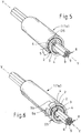
- Two examples of coverings 1a produced with the adhesive tape 1 are shown in FIG Figures 5 and 6 shown.
- a preferred application of the adhesive tape 1 according to the invention is the wrapping of cable sets as an elongated product, which is shown in FIG Figures 5 and 6 is designated by the reference numeral 8 in each case.
- a cable harness in particular for the automotive industry, can be formed from several, each provided with insulation, in particular electrical lines 9 by at least partial wrapping - for example at non-insulated points of lines 9 - with the adhesive tape 1 according to the invention.
- the wrapping is not done in a helical manner, as is usual, but in such a way that a longitudinal axis of the tape (in Figs. 1 to 4 denoted by "XX”) is aligned essentially parallel to the direction YY of the elongated product 8.
- the adhesive tape 1 lies around the item in the form of an Archimedean spiral.
- Essentially parallel means that, for example, lateral kinks or twists running at a small acute angle, as can occur in cables 9 in a cable set 8 consisting of several conductors, are not taken into account.
- the running or longitudinal direction XX of the adhesive tape 1 is therefore essentially identical to the longitudinal direction YY of the item 8 to be wrapped.
- FIG. 3 shows an envelope 1a made from an inventive adhesive tape 1 according to the embodiment in FIG Fig. 1 is made.
- the only protruding area 5 that is present is located as a closure at the outer end of the helically wound adhesive tape 1.
- the inside of the envelope 1a is completely tack-free.
- FIG. 3 shows an envelope 1a made from an adhesive tape 1 according to the invention according to the embodiment in FIG Fig. 2 is made.
- One of the two protruding areas 5a that is present lies at the outer end of the helically wound adhesive tape 1, while the other protruding area 5b lies on the inside and has a fixing effect on the elongated product 8.
- both the first carrier 2 and the second carrier 4 consist of a film or a film composite material or a fabric, in particular a polyester or polyamide fabric, or a fleece. It is possible here by means of special carrier combinations to set a desired profile of properties for the adhesive tape 1 according to the invention.
- LV 312 "Protection systems for wiring harnesses in motor vehicles" contains test regulations as well as criteria and quantitative information for application-related important variables, such as temperature class, noise dampening behavior and abrasion resistance.
- LV 312 provides the classification given in Table 1 below.
- Table 1 Temperature classes according to LV 312 great Continuous use temperature Short term temperature Thermal overload temperature T U to T O in ° C (T O + 25) ° C (T O + 50) ° C A. - 40 to 85 110 ⁇ 2 135 ⁇ 3 B. - 40 to 100 125 ⁇ 3 150 ⁇ 3 C. - 40 to 125 150 ⁇ 3 175 ⁇ 3 D. - 40 to 150 175 ⁇ 3 200 ⁇ 3
- LV 312 provides the classification given in Table 2 below.
- Table 2 Abrasion protection classes according to LV 312 Abrasion class Requirement (number of strokes) A - no abrasion protection ⁇ 100 B - low abrasion protection 100-499 C - medium abrasion protection 500 - 999 D - high abrasion protection 1000-4999 E - very high abrasion protection 5000 and more
- LV 312 also provides for a division into five classes with regard to noise damping behavior, which is shown in Table 3 below.
- Table 3 Noise reduction classes according to LV 312 Noise reduction class Requirement A - no noise reduction 0 to 2 dB (A) B - low noise attenuation > 2 to 5 dB (A) C - medium noise reduction > 5 to 10 dB (A) D - high noise attenuation > 10 to 15 dB (A) E - very high noise attenuation > 15 dB (A)
- the guideline also describes, for example, test methods for the compatibility of adhesive tapes with electrical vehicle cables and for chemical resistance, fogging and flagging behavior.
- an adhesive tape 1 according to the invention not only enables easier production, but the adhesive tape 1 according to the invention also ensures improved strength of the closure. Furthermore, as mentioned, the largely tack-free inside provides the possibility of producing highly flexible sheaths 1a.
- UV-crosslinked acrylate adhesives hereinafter: UV acrylates
- 8 envelopes 1a are obtained for the elongated good, which can also be used in temperature class D according to Table 1 above under normal bending stress.
- the use of rubber-based adhesives is also possible, with the material-economical advantage of the invention with regard to the amount of adhesive already mentioned.
- the protective layer 1a corresponds at least to that of a conventional adhesive tape wound with a 50 percent overlap, but in the applied or assembled state with the structure: carrier 2 - adhesive layer 3 - carrier 4. In some areas, this thickness DS - as shown - can also be greater be.
- the grammage - and thus a thickness D3 - of the adhesive layer 3 depends in particular on the surface structure of the carrier 2, 4.
- an optimal specific mass of the adhesive layer 3 is preferably in the range from 70 to 140 g / m 2 , while a grammage of 40 to 80 g / m 2 appears to be sufficient for film carriers.
- the abrasion protection effect of an adhesive tape 1 according to the invention is increased again by the fact that the protective sheath 1a made from the adhesive tape 1 according to the invention is on the item 8, such as B. a cable set, can be movable. As a result, the forces acting are distributed over a larger area and can therefore only cause comparatively less damage. This effect becomes measurable when the casing 1a is movably attached to the abrasion mandrel of an abrasion measuring apparatus according to LV 312.
- Table 5 contains further information on the structure and the product properties of exemplary designs C1, C2, C3, only design C1 being an adhesive tape 1 according to the invention.
- Table 5 Basic data for adhesive tapes according to the invention size C1 C2 C3 first carrier 2 (outside) Aluminum composite foil PET fabric 120 g / m 2 PET fabric 120 g / m 2 Second carrier 4 (inside) PET fabric 120 g / m 2 PET fabric 120 g / m 2 PET fleece 240 g / m 2 Adhesive layer 3 UV acrylate 50 g / m 2 UV acrylate 140 g / m 2 Synthetic rubber 140 g / m 2 Thickness D (DIN EN 1942) 0.3 mm 0.5 mm 0.9 mm Breaking strength (DIN EN 14410) 300 N / cm 580 N / cm 300 N / cm Elongation at break (DIN EN 14410) 40% 45% 45% Noise reduction Class a class B Class D. Abrasion resistance Class E. Class E. Class E.
- the carrier composite of the first carrier 2 in the version C1 - referred to in the table field as "aluminum composite film” - consisted of a film which was in turn produced from a 9 ⁇ m thick aluminum film and a 15 ⁇ m thick PET film.
- the invention is not limited to the exemplary embodiment described - e.g. B. to the specified thicknesses of the layers of the aluminum composite material - limited., But also includes within the scope of claim 1 further combinations of Carriers 2, 4, which also take other adhesive tape properties into account, such as compatibility with electrical vehicle lines, chemical resistance, fogging and / or flagging behavior.
Landscapes
- Chemical & Material Sciences (AREA)
- Organic Chemistry (AREA)
- Adhesive Tapes (AREA)
Claims (12)
- Bande adhésive (1) pour l'enveloppement longitudinal d'un article allongé (8), comprenant un premier support en forme de bande (2) et au moins une couche adhésive (3) appliquée sur un côté du premier support (2), qui s'étend sur la largeur totale (B2) du premier support (2), un deuxième support (4) étant stratifié sur la couche adhésive (3), qui présente une largeur (B4) plus faible que la largeur (B2) du premier support (2), le premier support (2) pourvu de la couche adhésive (3) dépassant ainsi au moins par rapport à un bord latéral du deuxième support (4), le deuxième support (4) n'étant pas muni d'une couche adhésive et étant destiné à être le support le plus proche de l'article allongé (8) à l'état enveloppé de l'article allongé (8), caractérisée en ce que le premier support (2) est constitué par un matériau composite d'aluminium et le deuxième support (4) est constitué par un tissu de PET, le matériau composite d'aluminium étant constitué par au moins deux couches, parmi lesquelles la première couche est une couche d'aluminium et la deuxième couche, sur laquelle la couche adhésive (3) est appliquée, est constituée par une feuille en matière plastique résistante à la température ou par un matériau support textile.
- Bande adhésive (1) selon la revendication 1, caractérisée en ce que le deuxième support (4) est aligné au niveau d'un bord latéral (K4) avec un bord latéral (K2) du premier support (2), le premier support (2) pourvu de la couche adhésive (3) dépassant par rapport à l'autre bord latéral (K4) du deuxième support (4).
- Bande adhésive (1) selon la revendication 1, caractérisée en ce que le premier support (2) pourvu de la couche adhésive (3) dépasse bilatéralement par rapport aux bords latéraux (K4) du deuxième support (4).
- Bande adhésive (1) selon la revendication 3, caractérisée en ce que le deuxième support (4) est agencé asymétriquement par rapport à l'axe central s'étendant longitudinalement (X-X) du premier support (2).
- Bande adhésive (1) selon la revendication 1, caractérisée en ce que le premier support (2) pourvu de la couche adhésive (3) dépasse unilatéralement par rapport à un bord latéral (K4) du deuxième support (4) et le deuxième support (4) dépasse, sur l'autre côté du premier support (2), unilatéralement par rapport à un bord latéral (K2) du premier support (2).
- Bande adhésive (1) selon l'une quelconque des revendications 1 à 5, caractérisée en ce que le deuxième support (4) est constitué par au moins deux parties de support séparées l'une de l'autre (4a, 4b), la première partie de support (4a) présentant une première largeur (B4a) et la deuxième partie de support (4b) présentant une deuxième largeur (B4b), et la somme des largeurs (B4a, B4b) des parties de support (4a, 4b) étant inférieure à la largeur (B2) du premier support (2).
- Bande adhésive (1) selon l'une quelconque des revendications 1 à 6, caractérisée en ce que des zones (5, 5a, 5b, 5c) du premier support (2) couvertes avec la couche adhésive (3), dépassant latéralement par rapport au deuxième support (4), sont recouvertes avec un papier de séparation ou une feuille de séparation (7).
- Bande adhésive (1) selon l'une quelconque des revendications 1 à 7, caractérisée en ce que la couche adhésive (3) est constituée par un adhésif acrylate réticulé par UV ou par un adhésif à base de caoutchouc.
- Bande adhésive (1) selon l'une quelconque des revendications 1 à 8, caractérisée en ce que la couche adhésive (3) présente un grammage dans la plage allant de 70 à 140 g/m2.
- Faisceau de câbles, constitué par un ensemble de câbles (8), qui comprend un enrobage (1a) avec une bande adhésive (1) selon l'une quelconque des revendications 1 à 9, un axe longitudinal (X-X) de la bande adhésive (1) étant orienté essentiellement en parallèle à la direction d'extension (Y-Y) de l'ensemble de câbles (8).
- Faisceau de câbles selon la revendication 10, caractérisé en ce que la bande adhésive (1) est enroulée, observé dans la section transversale, sous la forme d'une spirale d'Archimède autour de l'ensemble de câbles (8).
- Faisceau de câbles selon la revendication 10 ou 11, caractérisé en ce que l'enrobage (1a) est mobile sur l'ensemble de câbles (8).
Applications Claiming Priority (1)
| Application Number | Priority Date | Filing Date | Title |
|---|---|---|---|
| DE202007012475U DE202007012475U1 (de) | 2007-09-06 | 2007-09-06 | Klebeband zur Längsummantelung von langgestrecktem Gut |
Publications (2)
| Publication Number | Publication Date |
|---|---|
| EP2034576A1 EP2034576A1 (fr) | 2009-03-11 |
| EP2034576B1 true EP2034576B1 (fr) | 2020-10-07 |
Family
ID=39994202
Family Applications (1)
| Application Number | Title | Priority Date | Filing Date |
|---|---|---|---|
| EP08162060.1A Active EP2034576B1 (fr) | 2007-09-06 | 2008-08-08 | Bande adhésive destinée à l'enveloppement de marchandises longitudinales |
Country Status (2)
| Country | Link |
|---|---|
| EP (1) | EP2034576B1 (fr) |
| DE (1) | DE202007012475U1 (fr) |
Families Citing this family (22)
| Publication number | Priority date | Publication date | Assignee | Title |
|---|---|---|---|---|
| DE102008056554A1 (de) * | 2008-11-10 | 2010-05-20 | Tesa Se | Ummantelung zum Ummanteln von langgestrecktem Gut wie insbesondere Kabelsätzen und Verfahren zur Ummantelung |
| DE102011005200A1 (de) * | 2011-03-07 | 2012-09-13 | Tesa Se | Klebeband zum Ummanteln von langgestrecktem Gut wie insbesondere Kabelsätzen und Verfahren zur Ummantelung |
| DE102011005162A1 (de) * | 2011-03-07 | 2012-09-13 | Tesa Se | Klebeland für die Kabelbandagierung |
| DE102011005763A1 (de) * | 2011-03-18 | 2012-09-20 | Tesa Se | Klebeband zum Ummanteln von langgestrecktem Gut wie insbesondere Kabelsätzen und Verfahren zur Ummantelung |
| DE202011110445U1 (de) | 2011-10-06 | 2014-01-22 | Coroplast Fritz Müller Gmbh & Co. Kg | Vorrichtung zur Herstellung eines insbesondere zur Längsummantelung von langgestrecktem Gut verwendbaren Klebebandes |
| PL2578401T3 (pl) | 2011-10-06 | 2014-11-28 | Coroplast Fritz Mueller Gmbh & Co Kg | Sposób produkcji taśmy klejącej, w szczególności mającej zastosowanie do wzdłużnego pokrywania podłużnych wyrobów, oraz urządzenie do realizacji tego sposobu |
| WO2014193924A1 (fr) * | 2013-05-28 | 2014-12-04 | Federal-Mogul Powertrain, Inc. | Manchon textile enroulé ayant un mécanisme de fermeture lié et procédé de fabrication de ce dernier |
| DE102013111219B4 (de) | 2013-10-10 | 2024-04-18 | Coroplast Fritz Müller Gmbh & Co. Kg | "Umhüllungsmittel für ein langgestrecktes Gut und dessen Verwendung" |
| DE102014113769A1 (de) * | 2014-09-23 | 2016-03-24 | Certoplast Vorwerk & Sohn Gmbh | Verfahren zur Herstellung einer Ummantelung für langgestrecktes Gut |
| JP6768654B2 (ja) * | 2014-11-26 | 2020-10-14 | フェデラル−モーグル・パワートレイン・リミテッド・ライアビリティ・カンパニーFederal−Mogul Powertrain Llc | 不織音響スリーブおよびその構築方法 |
| DE202017100009U1 (de) | 2017-01-03 | 2017-01-20 | Certoplast Technische Klebebänder Gmbh | Klebeband, insbesondere Wickelband |
| CN107123546B (zh) * | 2017-06-23 | 2018-10-26 | 中达电子(江苏)有限公司 | 绕线、绕组及绕线的制备方法 |
| CN110137682A (zh) * | 2018-02-02 | 2019-08-16 | 康普技术有限责任公司 | 用于调节电调天线的组件以及电调天线系统 |
| EP3957695A1 (fr) * | 2020-08-17 | 2022-02-23 | tesa SE | Bande adhésive permettant d'envelopper une marchandise allongée telle que, en particulier les faisceaux de câbles et procédé d'enveloppement |
| DE102021201856A1 (de) | 2021-02-26 | 2022-09-01 | Tesa Se | Klebeband zum Ummanteln von langgestrecktem Gut wie insbesondere Kabelsätzen und Verfahren zur Ummantelung |
| DE102021115573A1 (de) * | 2021-06-16 | 2022-12-22 | Tdk Electronics Ag | Anordnung zum Schutz einer Sonsorvorrichtung |
| WO2023051890A1 (fr) | 2021-09-28 | 2023-04-06 | Coroplast Fritz Müller Gmbh & Co. Kg | Produit allongé à blindage électromagnétique revêtu longitudinalement, manchon pour le revêtement du produit et son utilisation |
| DE102021210866A1 (de) | 2021-09-28 | 2023-03-30 | Tesa Se | Klebeband zum Ummanteln von langgestrecktem Gut wie insbesondere Kabelsätzen und Verfahren zur Ummantelung |
| DE102021125009A1 (de) | 2021-09-28 | 2023-03-30 | Coroplast Fritz Müller GmbH & Co. K. G. | Längsummanteltes, elektromagnetisch abgeschirmtes, langgestrecktes Gut sowie Umhüllung zur Ummantelung des Gutes und Verwendung derselben |
| DE202022101548U1 (de) | 2022-03-24 | 2022-04-06 | Certoplast Technische Klebebänder Gmbh | Klebeband insbesondere Wickelband zur Ummantelung von Kabeln in Automobilen |
| DE202022105886U1 (de) | 2022-10-19 | 2022-11-14 | Certoplast Technische Klebebänder Gmbh | Klebeband |
| DE102022127834A1 (de) | 2022-10-21 | 2024-05-02 | Tesa Se | Klebeband zum Umwickeln von langgestrecktem Gut |
Citations (11)
| Publication number | Priority date | Publication date | Assignee | Title |
|---|---|---|---|---|
| US4327246A (en) * | 1980-02-19 | 1982-04-27 | Belden Corporation | Electric cables with improved shielding members |
| DE9400574U1 (de) | 1993-10-06 | 1994-04-14 | Coroplast Fritz Mueller Kg | Klebeband insbesondere zum Umwickeln eines Leitungssatzes |
| DE29510907U1 (de) | 1995-07-06 | 1995-10-19 | Mohr Karl Eugen | Schutzummantelung für Kabel, Litzen u.dgl. |
| DE29711387U1 (de) * | 1997-06-30 | 1997-11-06 | Bentley Harris Inc | Ummantelung für langgestreckte Gegenstände |
| DE10036805A1 (de) * | 2000-07-28 | 2002-02-07 | Tesa Ag | Verfahren zur Ummantelung von langgestrecktem Gut, wie insbesondere Kabelsätzen |
| DE10042732A1 (de) | 2000-08-31 | 2002-03-28 | Tesa Ag | Verfahren zur Ummantelung von langgestrecktem Gut, wie insbesondere Kabelsätzen mit einem Klebeband |
| EP1615238A1 (fr) | 2004-07-10 | 2006-01-11 | Coroplast Fritz Müller GmbH & Co. KG | ruban adhesive technique ayant une isolation thermique et faisceau de cables ayant une resistance thermique elevee |
| DE102005013124A1 (de) | 2005-03-18 | 2006-09-21 | Certoplast Vorwerk & Sohn Gmbh | Schutzummantelung zur im Querschnitt spiralförmigen Längsumhüllung von langgestrecktem Gut sowie zugehöriges Verfahren |
| WO2006108871A1 (fr) | 2005-04-14 | 2006-10-19 | Tesa Ag | Procede pour entourer un produit oblong, comme notamment des faisceaux de cables, d'une gaine |
| US20070104927A1 (en) | 2005-11-07 | 2007-05-10 | Yazaki Corporation | Covering sheet and wire harness |
| US20070154684A1 (en) * | 2005-12-30 | 2007-07-05 | Baer Angela L | Self-adhesive protective substrate |
-
2007
- 2007-09-06 DE DE202007012475U patent/DE202007012475U1/de not_active Expired - Lifetime
-
2008
- 2008-08-08 EP EP08162060.1A patent/EP2034576B1/fr active Active
Patent Citations (12)
| Publication number | Priority date | Publication date | Assignee | Title |
|---|---|---|---|---|
| US4327246A (en) * | 1980-02-19 | 1982-04-27 | Belden Corporation | Electric cables with improved shielding members |
| DE9400574U1 (de) | 1993-10-06 | 1994-04-14 | Coroplast Fritz Mueller Kg | Klebeband insbesondere zum Umwickeln eines Leitungssatzes |
| DE29510907U1 (de) | 1995-07-06 | 1995-10-19 | Mohr Karl Eugen | Schutzummantelung für Kabel, Litzen u.dgl. |
| DE29711387U1 (de) * | 1997-06-30 | 1997-11-06 | Bentley Harris Inc | Ummantelung für langgestreckte Gegenstände |
| DE10036805A1 (de) * | 2000-07-28 | 2002-02-07 | Tesa Ag | Verfahren zur Ummantelung von langgestrecktem Gut, wie insbesondere Kabelsätzen |
| DE10042732A1 (de) | 2000-08-31 | 2002-03-28 | Tesa Ag | Verfahren zur Ummantelung von langgestrecktem Gut, wie insbesondere Kabelsätzen mit einem Klebeband |
| EP1615238A1 (fr) | 2004-07-10 | 2006-01-11 | Coroplast Fritz Müller GmbH & Co. KG | ruban adhesive technique ayant une isolation thermique et faisceau de cables ayant une resistance thermique elevee |
| DE102005013124A1 (de) | 2005-03-18 | 2006-09-21 | Certoplast Vorwerk & Sohn Gmbh | Schutzummantelung zur im Querschnitt spiralförmigen Längsumhüllung von langgestrecktem Gut sowie zugehöriges Verfahren |
| WO2006108871A1 (fr) | 2005-04-14 | 2006-10-19 | Tesa Ag | Procede pour entourer un produit oblong, comme notamment des faisceaux de cables, d'une gaine |
| DE102005017381A1 (de) | 2005-04-14 | 2006-10-19 | Tesa Ag | Verfahren zum Ummanteln von langgestrecktem Gut, wie insbesondere Kabelsätzen, mit einer Umhüllung |
| US20070104927A1 (en) | 2005-11-07 | 2007-05-10 | Yazaki Corporation | Covering sheet and wire harness |
| US20070154684A1 (en) * | 2005-12-30 | 2007-07-05 | Baer Angela L | Self-adhesive protective substrate |
Also Published As
| Publication number | Publication date |
|---|---|
| EP2034576A1 (fr) | 2009-03-11 |
| DE202007012475U1 (de) | 2009-01-08 |
Similar Documents
| Publication | Publication Date | Title |
|---|---|---|
| EP2034576B1 (fr) | Bande adhésive destinée à l'enveloppement de marchandises longitudinales | |
| EP2627539B1 (fr) | Ruban adhésif et enveloppe tubulaire produite à partir de ce ruban adhésif | |
| EP1848006B1 (fr) | Bande de colle destinée à l'enrobage de biens allongés, utilisation de cette bande de colle tout comme faisceau de câble doté de cette bande de colle | |
| EP1615238B2 (fr) | Ruban adhesive technique ayant une isolation thermique et faisceau de cables ayant une resistance thermique elevee | |
| EP3197968B1 (fr) | Procédé pour la fabrication d'une gaine pour un produit allongé | |
| EP1988140B1 (fr) | Bande adhésive reflétant la chaleur dotée d'une protection anti-abrasive élevée | |
| DE19732958A1 (de) | Klebeband zum Ummanteln von langgestrecktem Gut, wie Kabelsätzen, Kunststoffprofilen od. dgl. | |
| EP0647691B1 (fr) | Ruban adhésif ainsi que son utilisation pour envelopper un faisceau de fils conducteurs | |
| DE102013111219B4 (de) | "Umhüllungsmittel für ein langgestrecktes Gut und dessen Verwendung" | |
| EP1983036A1 (fr) | Bande adhésive refléchissant la chaleur | |
| EP2497807A1 (fr) | Ruban adhésif pour le bandage de câbles | |
| EP3765577B1 (fr) | Bande adhésive, en particulier bande enveloppante | |
| EP0525519B1 (fr) | Feuille composite rétrécissable | |
| DE102008025580A1 (de) | Wickelkern für Klebebänder | |
| DE102014114794A1 (de) | Verfahren zur Herstellung einer Ummantelung für langgestrecktes Gut | |
| EP3713758A1 (fr) | Procédé pour la fabrication d'une gaine pour un produit allongé | |
| WO2023051890A1 (fr) | Produit allongé à blindage électromagnétique revêtu longitudinalement, manchon pour le revêtement du produit et son utilisation | |
| DE102021125009A1 (de) | Längsummanteltes, elektromagnetisch abgeschirmtes, langgestrecktes Gut sowie Umhüllung zur Ummantelung des Gutes und Verwendung derselben | |
| DE19740722B4 (de) | Elektrisches Kabel mit einem überlappten Außenleiter | |
| EP2898032B1 (fr) | Bande d'étanchéité | |
| DE10054909A1 (de) | Klebeband | |
| DE102020109574A1 (de) | Rollosystem für ein Kraftfahrzeug sowie Verfahren zur Herstellung eines Rollosystems | |
| DE102016214483A1 (de) | Datenleitung und Verfahren zur Herstellung einer Datenleitung | |
| EP2874157A1 (fr) | Câble électrique | |
| DE102011014397A1 (de) | Klebeband mit doppelseitig selbstklebendem Träger |
Legal Events
| Date | Code | Title | Description |
|---|---|---|---|
| PUAI | Public reference made under article 153(3) epc to a published international application that has entered the european phase |
Free format text: ORIGINAL CODE: 0009012 |
|
| AK | Designated contracting states |
Kind code of ref document: A1 Designated state(s): AT BE BG CH CY CZ DE DK EE ES FI FR GB GR HR HU IE IS IT LI LT LU LV MC MT NL NO PL PT RO SE SI SK TR |
|
| AX | Request for extension of the european patent |
Extension state: AL BA MK RS |
|
| 17P | Request for examination filed |
Effective date: 20090825 |
|
| 17Q | First examination report despatched |
Effective date: 20091022 |
|
| AKX | Designation fees paid |
Designated state(s): DE ES FR GB IT |
|
| STAA | Information on the status of an ep patent application or granted ep patent |
Free format text: STATUS: EXAMINATION IS IN PROGRESS |
|
| RIC1 | Information provided on ipc code assigned before grant |
Ipc: C09J 7/22 20180101ALI20200124BHEP Ipc: C09J 7/21 20180101ALI20200124BHEP Ipc: H02G 3/04 20060101AFI20200124BHEP |
|
| GRAP | Despatch of communication of intention to grant a patent |
Free format text: ORIGINAL CODE: EPIDOSNIGR1 |
|
| STAA | Information on the status of an ep patent application or granted ep patent |
Free format text: STATUS: GRANT OF PATENT IS INTENDED |
|
| INTG | Intention to grant announced |
Effective date: 20200310 |
|
| GRAS | Grant fee paid |
Free format text: ORIGINAL CODE: EPIDOSNIGR3 |
|
| GRAA | (expected) grant |
Free format text: ORIGINAL CODE: 0009210 |
|
| STAA | Information on the status of an ep patent application or granted ep patent |
Free format text: STATUS: THE PATENT HAS BEEN GRANTED |
|
| AK | Designated contracting states |
Kind code of ref document: B1 Designated state(s): DE ES FR GB IT |
|
| REG | Reference to a national code |
Ref country code: GB Ref legal event code: FG4D Free format text: NOT ENGLISH |
|
| REG | Reference to a national code |
Ref country code: DE Ref legal event code: R096 Ref document number: 502008017150 Country of ref document: DE |
|
| PG25 | Lapsed in a contracting state [announced via postgrant information from national office to epo] |
Ref country code: ES Free format text: LAPSE BECAUSE OF FAILURE TO SUBMIT A TRANSLATION OF THE DESCRIPTION OR TO PAY THE FEE WITHIN THE PRESCRIBED TIME-LIMIT Effective date: 20201007 |
|
| REG | Reference to a national code |
Ref country code: DE Ref legal event code: R026 Ref document number: 502008017150 Country of ref document: DE |
|
| PLBI | Opposition filed |
Free format text: ORIGINAL CODE: 0009260 |
|
| PLAX | Notice of opposition and request to file observation + time limit sent |
Free format text: ORIGINAL CODE: EPIDOSNOBS2 |
|
| 26 | Opposition filed |
Opponent name: CERTOPLAST TECHNISCHE KLEBEBAENDER GMBH Effective date: 20210617 |
|
| PG25 | Lapsed in a contracting state [announced via postgrant information from national office to epo] |
Ref country code: IT Free format text: LAPSE BECAUSE OF FAILURE TO SUBMIT A TRANSLATION OF THE DESCRIPTION OR TO PAY THE FEE WITHIN THE PRESCRIBED TIME-LIMIT Effective date: 20201007 |
|
| PLBB | Reply of patent proprietor to notice(s) of opposition received |
Free format text: ORIGINAL CODE: EPIDOSNOBS3 |
|
| GBPC | Gb: european patent ceased through non-payment of renewal fee |
Effective date: 20210808 |
|
| PG25 | Lapsed in a contracting state [announced via postgrant information from national office to epo] |
Ref country code: GB Free format text: LAPSE BECAUSE OF NON-PAYMENT OF DUE FEES Effective date: 20210808 |
|
| REG | Reference to a national code |
Ref country code: DE Ref legal event code: R100 Ref document number: 502008017150 Country of ref document: DE |
|
| PLCK | Communication despatched that opposition was rejected |
Free format text: ORIGINAL CODE: EPIDOSNREJ1 |
|
| PLBN | Opposition rejected |
Free format text: ORIGINAL CODE: 0009273 |
|
| STAA | Information on the status of an ep patent application or granted ep patent |
Free format text: STATUS: OPPOSITION REJECTED |
|
| 27O | Opposition rejected |
Effective date: 20220920 |
|
| P01 | Opt-out of the competence of the unified patent court (upc) registered |
Effective date: 20230525 |
|
| PGFP | Annual fee paid to national office [announced via postgrant information from national office to epo] |
Ref country code: FR Payment date: 20230726 Year of fee payment: 16 |
|
| PGFP | Annual fee paid to national office [announced via postgrant information from national office to epo] |
Ref country code: DE Payment date: 20231026 Year of fee payment: 16 |