EP2034493A1 - R-t-b-sintermagnet - Google Patents
R-t-b-sintermagnet Download PDFInfo
- Publication number
- EP2034493A1 EP2034493A1 EP07742819A EP07742819A EP2034493A1 EP 2034493 A1 EP2034493 A1 EP 2034493A1 EP 07742819 A EP07742819 A EP 07742819A EP 07742819 A EP07742819 A EP 07742819A EP 2034493 A1 EP2034493 A1 EP 2034493A1
- Authority
- EP
- European Patent Office
- Prior art keywords
- magnet
- coercivity
- rare
- mole fraction
- earth
- Prior art date
- Legal status (The legal status is an assumption and is not a legal conclusion. Google has not performed a legal analysis and makes no representation as to the accuracy of the status listed.)
- Granted
Links
Images


Classifications
-
- H—ELECTRICITY
- H01—ELECTRIC ELEMENTS
- H01F—MAGNETS; INDUCTANCES; TRANSFORMERS; SELECTION OF MATERIALS FOR THEIR MAGNETIC PROPERTIES
- H01F1/00—Magnets or magnetic bodies characterised by the magnetic materials therefor; Selection of materials for their magnetic properties
- H01F1/01—Magnets or magnetic bodies characterised by the magnetic materials therefor; Selection of materials for their magnetic properties of inorganic materials
- H01F1/03—Magnets or magnetic bodies characterised by the magnetic materials therefor; Selection of materials for their magnetic properties of inorganic materials characterised by their coercivity
- H01F1/032—Magnets or magnetic bodies characterised by the magnetic materials therefor; Selection of materials for their magnetic properties of inorganic materials characterised by their coercivity of hard-magnetic materials
- H01F1/04—Magnets or magnetic bodies characterised by the magnetic materials therefor; Selection of materials for their magnetic properties of inorganic materials characterised by their coercivity of hard-magnetic materials metals or alloys
- H01F1/047—Alloys characterised by their composition
- H01F1/053—Alloys characterised by their composition containing rare earth metals
- H01F1/055—Alloys characterised by their composition containing rare earth metals and magnetic transition metals, e.g. SmCo5
- H01F1/057—Alloys characterised by their composition containing rare earth metals and magnetic transition metals, e.g. SmCo5 and IIIa elements, e.g. Nd2Fe14B
- H01F1/0571—Alloys characterised by their composition containing rare earth metals and magnetic transition metals, e.g. SmCo5 and IIIa elements, e.g. Nd2Fe14B in the form of particles, e.g. rapid quenched powders or ribbon flakes
- H01F1/0575—Alloys characterised by their composition containing rare earth metals and magnetic transition metals, e.g. SmCo5 and IIIa elements, e.g. Nd2Fe14B in the form of particles, e.g. rapid quenched powders or ribbon flakes pressed, sintered or bonded together
- H01F1/0577—Alloys characterised by their composition containing rare earth metals and magnetic transition metals, e.g. SmCo5 and IIIa elements, e.g. Nd2Fe14B in the form of particles, e.g. rapid quenched powders or ribbon flakes pressed, sintered or bonded together sintered
-
- C—CHEMISTRY; METALLURGY
- C22—METALLURGY; FERROUS OR NON-FERROUS ALLOYS; TREATMENT OF ALLOYS OR NON-FERROUS METALS
- C22C—ALLOYS
- C22C38/00—Ferrous alloys, e.g. steel alloys
- C22C38/005—Ferrous alloys, e.g. steel alloys containing rare earths, i.e. Sc, Y, Lanthanides
-
- C—CHEMISTRY; METALLURGY
- C22—METALLURGY; FERROUS OR NON-FERROUS ALLOYS; TREATMENT OF ALLOYS OR NON-FERROUS METALS
- C22C—ALLOYS
- C22C38/00—Ferrous alloys, e.g. steel alloys
- C22C38/04—Ferrous alloys, e.g. steel alloys containing manganese
-
- C—CHEMISTRY; METALLURGY
- C22—METALLURGY; FERROUS OR NON-FERROUS ALLOYS; TREATMENT OF ALLOYS OR NON-FERROUS METALS
- C22C—ALLOYS
- C22C38/00—Ferrous alloys, e.g. steel alloys
- C22C38/06—Ferrous alloys, e.g. steel alloys containing aluminium
-
- C—CHEMISTRY; METALLURGY
- C22—METALLURGY; FERROUS OR NON-FERROUS ALLOYS; TREATMENT OF ALLOYS OR NON-FERROUS METALS
- C22C—ALLOYS
- C22C38/00—Ferrous alloys, e.g. steel alloys
- C22C38/10—Ferrous alloys, e.g. steel alloys containing cobalt
Definitions
- the present invention relates to an R-T-B (rare-earth-iron-boron) based sintered magnet.
- R-T-B based sintered magnets have so good magnetic properties as to find a wide variety of applications including various types of motors and actuators and are now one of indispensable materials for the electronics industry. Also, their applications have been appreciably broadened to keep up with the recent trend toward energy saving.
- R-T-B based magnets One of the old drawbacks of R-T-B based magnets is their relative low Curie temperature of approximately 300 °C, at which their ferromagnetism is lost. And irreversible flux loss will occur easily in R-T-B based magnets.
- various measures have been taken. For example, some people tried to increase the coercivity of the R-T-B based magnets by adjusting the combination of rare-earth elements to add. Other people attempted to increase the Curie temperature by adding Co as disclosed in Patent Document No. 1.
- Patent Document No. 2 One of those methods is disclosed in Patent Document No. 2, in which heavy rare-earth elements such as Dy and Tb are included in particular percentages in the rare-earth elements. In practice, only Dy and Tb turned out to be effective enough. This method is adopted in order to increase the coercivity of the magnet as a whole, as well as the anisotropic magnetic field of its main phase that determines its magnetic properties.
- the additive elements such as Ti, V, Cr, Zr, Nb, Mo, Hf and W disclosed in Patent Document No. 5, for example, hinder the growth of crystal grains during the sintering process and reduce the size of the resultant metallurgical structure of the sintered body, thus contributing to increasing the coercivity.
- Non-Patent Document No. 1 discloses magnetic properties that an R 2 Fe 14 B compound would have with various rare-earth elements, and the composition can be determined by reference to such data.
- the anisotropic magnetic field generated by Pr has temperature dependence, which is heavier than that of Nd. For that reason, even though Pr could increase the coercivity at room temperature, the coercivity to be exhibited by the additive Pr would rather be lower than that to be exhibited by Nd in a temperature range exceeding 80 °C. That is why the addition of Pr would be counteractive at least in terms of thermal resistance.
- the method that uses heavy rare-earth elements is most effective because the decrease in magnetic flux density is relatively small according to that method. According to any of the other methods mentioned above, however, a significant decrease in the magnetic flux density of the magnet is inevitable. And those methods are applicable to only a narrow field. For that reason, in making magnets actually, these techniques are used in an appropriate combination.
- those heavy rare-earth elements such as Dy and Tb are among the rarest and expensive ones of all rare-earth elements. For that reason, if a lot of such heavy rare-earth elements should be used, then the price of the magnets would rise.
- resource-related restrictions on those heavy rare-earth elements have become an issue these days because those rare elements are available only in very limited quantities and in very narrow areas.
- an object of the present invention is to provide a means for increasing the coercivity that would work independently of the effects caused by a heavy rare-earth element such as Dy or Tb.
- An R-T-B based sintered magnet according to the present invention comprises: 12 at% to 17 at% of a rare-earth element R; 5.0 at% to 8.0 at% of boron B; 0.02 at% to 0.3 at% of Mn; and a transition metal T as the balance.
- the rare-earth element R is at least one element selected from the rare-earth elements, including Y (yttrium), and includes 0.2 at% to 10 at% of Pr.
- the transition element T includes Fe as its main ingredient.
- the magnet includes at least one of Tb and Dy as the rare-earth element R.
- the magnet includes 20 at% or less of Co as the transition metal T.
- An R-T-M-B based sintered magnet according the present invention comprising: 12 at% to 17 at% of a rare-earth element R; 5.0 at% to 8.0 at% of boron B; 0.02 at% to 0.3 at% of Mn; more than 0 at% to 5.0 at% of an additive element M; and a transition metal T as the balance.
- the rare-earth element R is at least one element selected from the rare-earth elements, including Y (yttrium), and includes 0.2 at% to 10 at% of Pr.
- the transition element T includes Fe as its main ingredient.
- the additive element M is at least one element selected from the group consisting of Al, Ni, Cu, Zn, Ga, Ag, In, Sn, Bi, Ti, V, Cr, Zr, Nb, Mo, Hf, Ta and W.
- the magnet includes at least one of Tb and Dy as the rare-earth element R.
- the magnet includes 20 at% or less of Co as the transition metal T.
- an R-T-B based sintered magnet includes Pr as an essential element and an additive Mn in an amount that falls within a predetermined range, its coercivity at around room temperature can be increased and higher coercivity than conventional magnets' can be achieved even at high temperatures of 80 °C or more. Also, by adding a predetermined amount of Mn, the sintering reaction can be promoted during the manufacturing process of the sintered magnet. As a result, the sintering process can be done either at a lower temperature or in a shorter time and the sintered magnet can have a homogenized structure. Consequently, the loop squareness of the demagnetization curve can be improved as well.
- the present inventors discovered that by using Pr as one of the rare-earth elements and adding Mn to the composition of a magnet, its coercivity at room temperature could be increased and the decrease in coercivity at high temperatures of 80 °C or more, which would otherwise be caused in a conventional magnet with Pr, could be minimized.
- An R-T-B based sintered magnet according to the present invention has a composition including: 12 at% to 17 at% of a rare-earth element R; 5.0 at% to 8.0 at% of boron B; 0.02 at% to 0.3 at% of Mn; and a transition metal T as the balance.
- the rare-earth element R is at least one element selected from the rare-earth elements, including Y (yttrium), and includes 0.2 at% to 10 at% of Pr.
- the transition element T includes Fe as its main element.
- At least one element selected from the group consisting of Ni, Cu, Zn, Ga, Ag, In, Sn, Bi, Ti, V, Cr, Zr, Nb, Mo, Hf, Ta and W may be added as the additive element M.
- the element of rare-earth element(s) according to the present invention is one of the most important factors to achieve the effects of the present invention.
- Nd is an indispensable element.
- R includes Nd as an essential element and a predetermined amount of R is added thereto in order to increase the coercivity.
- the lower limit of a preferred composition range for Pr is 0.2 at%, more preferably 0.5 at%.
- the upper limit of the Pr range is preferably 10 at%, more preferably 8.0 at%.
- the higher the mole fraction of R the higher the coercivity and the smaller the remanence tend to be. Specifically, if the mole fraction of R were less than 12 at%, the percentage of the R 2 T 14 B compound as the main phase would decrease, soft magnetic phases such as Fe would produce instead, and the coercivity would decrease significantly. On the other hand, if the mole fraction of R exceeded 17 at%, the percentage of the R 2 T 14 B compound as the main phase would decrease and the magnetization would drop. In addition, since excessive R would be concentrated as metal elements in the grain boundary of the main phase, and the anticorrosiveness might decrease significantly. For these reasons, the mole fraction of R is preferably 12 at% to 17 at%, more preferably 12.5 at% to 15 at%.
- One heavy rare-earth element or two such as Tb or Dy which would contribute to increasing the coercivity, may be added depending on the required level of magnetic properties (or the coercivity, among other things) because it would not counteract the effect of the present invention.
- Tb and/or Dy exceeded 6 at%, the resultant remanence would be lower than 1.1 T.
- the performance of the R-T-B based sintered magnet should be rather lower than that of an Sm-Co magnet.
- the material cost of the magnet would be too high to maintain its advantage over the Sm-Co magnet.
- the mole fraction of Tb and/or Dy is preferably 6 at% or less to achieve good industrial applicability.
- the other rare-earth elements, including Y, could also be included as inevitably contained impurities, although they would not produce any benefits as far as magnetic properties are concerned.
- Boron is an essential element to make an R-T-B based sintered magnet.
- the volume of the R 2 T 14 B compound as the main phase is determined by that of boron.
- the mole fraction of B is important. As long as it falls within the predetermined range to be defined below, the greater the mole fraction of B, the more easily sufficient coercivity could be achieved. Also, if the mole fraction of B were small, the coercivity would decrease steeply at a certain mole fraction of B. For that reason, from an industrial standpoint, it is particularly important to prevent the mole fraction of B from being short of that certain mole fraction. The greater the mole fraction of B, the lower the remanence.
- the mole fraction of B preferably falls within the range of 5.0 at% to 8.0 at%. To obtain a high-performance magnet, the mole fraction of B is more preferably 5.5 at% through 7.0 at%
- the transition metal T includes Fe as its main element and Mn as an essential element.
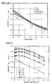
- FIG. 1 is a graph showing how the coercivity of an R-T-B based sintered magnet changed with the temperature in a situation where the mole fraction of Mn added was fixed at 0.01 at% and rare-earth elements were added in various combinations.
- FIG. 2A is a graph schematically showing the effect of the additive Mn on the coercivity of a magnet
- FIG. 2B is a partially enlarged one of the graph shown in FIG. 2A
- the curves #1 and #3 are the same as the ones shown in FIG. 1 .
- the curve #5 represents the characteristic of Sample #5, in which the mole fraction of Mn of Sample #3 was changed into 0.15 at%. Sample #5, to which a very small amount of Mn was added, exhibited higher coercivity than Sample #3 in the entire temperature range. As a result, the coercivity became higher than that of Sample #1 at a higher temperature.
- the mole fraction of Mn is preferably 0.3 at% or less. More preferably, the mole fraction of Mn is less than 0.2 at% because coercivity that is equal to or higher than the one produced at room temperature by adding either no Mn at all or 0.01 at% or less of Mn would be achieved in that case.
- the present inventors also discovered that even a very small amount of Mn added promoted the sintering reaction, which is another beneficial feature that contributes to producing a sintered magnet efficiently. Specifically, by adding Mn, the density of the magnet increased through the sintering reaction either at a lower temperature or in a shorter time. As a result, a sufficient sintered density could be achieved before the crystal grains grew too much. In addition, the magnet could have a further homogenized texture, and therefore, exhibited improved magnetic properties including improved loop squareness in its demagnetization curve.
- the additive Mn should account for at least 0.02 at%, more preferably 0.05 at% or more.
- Mn The only cost-effective element that would achieve the effect of improving the sinterability seems to be Mn. This is probably because Mn should be the only element to produce a solid solution substantially nowhere but in the main phase among various useful elements.
- Al and Cu were considered elements that would improve the sinterability. However, these elements would achieve the effect of improving the physical properties of the grain boundary phase but would act only indirectly on the sintering reaction of the R 2 T 14 B phase as the main phase. On the other hand, Mn will act directly on the sintering reaction of the main phase.
- a portion of Fe may sometimes be replaced with Co to improve the magnetic properties and the anticorrosiveness.
- the addition of Co would not counteract the effects of the present invention but would achieve some effects of increasing the Curie temperature and improving the anticorrosiveness. For that reason, Co is preferably added. If the mole fraction of Co added exceeded 20 at%, the magnetization would decrease significantly and the coercivity would drop steeply. That is why the upper limit of Co added is preferably 20 at%.
- the additive elements M can be classified into a first group consisting of Al, Ni, Cu, Zn, Ga, Ag, In, Sn and Bi and a second group consisting of Ti, V, Cr, Zr, Nb, Mo, Hf, Ta and W.
- An element in the first group is mainly present in the grain boundary in the metallurgical structure of the magnet and contributes to the interaction between the grain boundary and main phases. More specifically, the element will lower the melting point of the grain boundary phase to improve the sintering behavior of the magnet or increase the wettability between the main phase and the grain boundary phase, thereby expanding the grain boundary phase into the interface with the main phase more effectively and eventually increasing the coercivity of the magnet.
- the most effective ones are Al and Cu.
- any element in the second group will make the sintered structure finer and increase the coercivity by producing deposition with a high melting point, for example.
- No element in the first and second groups function as a ferromagnetic phase. For that reason, if a lot of such an element were added, the magnetization of the magnet would decrease. That is why the maximum mole fraction of these elements added is preferably 5 at% or less in total, more preferably 2 at% or less.
- F, Cl, Mg, Ca and other elements may get included during the process step of refining a rare-earth metal or may also stay in the composition of the magnet as it is.
- P and S may be included in the Fe material.
- Si and Al may not only come from a ferroboron alloy, which is a material source, but also get included as a crucible component while the material alloy to make the magnet is being melted.
- Material alloys may be prepared by any of various methods and used in any of various forms. Typical examples of preferred material alloys include an ingot alloy, a strip cast alloy, an atomized powder, a powder obtained by a reduction diffusion process and an alloy ribbon made by a rapid quenching process. Any of these material alloys may be used by itself. Or multiple material alloys of mutually different types may be used in combination as well. Still alternatively, a so-called "two-alloy process" that uses two alloys with different compositions in combination may also be adopted. In that case, in order to not only increase the coercivity but also improve the sinterability at high temperatures, Mn and Pr may be included in one or both of the two alloys.
- Mn and Pr may be included in one of the two alloys, of which the main phase has a composition closer to that of the magnetic alloy. Furthermore, just to improve the sinterability, Mn and Pr could be introduced into two different alloys and mixed together. In that case, however, the coercivity could not be increased at high temperatures so much as expected.
- the mother alloy may be subjected to a heat treatment in order to improve the uniformity of its structure or the distribution of elements or increase its homogeneity, for example.
- the pulverization process may also be carried out by any arbitrary method.
- An appropriate method is adopted according to the attribute of the start material. For example, if a strip cast alloy is used as a start material, the alloy often needs to go through the two pulverization process steps -- a coarse pulverization process step and a fine pulverization process step.
- the coarse pulverization may be done by either a mechanical pulverization process or a hydrogen decrepitation process, which can be used effectively to pulverize a rare-earth alloy.
- the "hydrogen decrepitation process” refers to a process in which a given alloy is enclosed along with hydrogen gas in a vessel, the hydrogen gas is absorbed into the alloy, and the alloy is pulverized by utilizing the strain to be caused by the variation in the volume of the alloy. According to this method, a lot of hydrogen will get included in the coarse powder. That is why the excessive hydrogen can be released by heating the coarse powder if necessary.
- the coarse powder may be classified with a sieve, for example, such that all of its particle sizes are equal to or smaller than a particular particle size.
- the fine pulverization usually gets done by a jet milling process that uses a jet flow.
- a mechanical fine pulverization process or a wet ball milling process that uses a dispersion medium may also be adopted.
- a pulverization assistant may be added in advance. This is particularly useful to increase the pulverization efficiency of the fine pulverization process step.
- the inert atmosphere is nitrogen gas.
- helium gas or argon gas needs to be used as the inert atmosphere.
- the objective particle size of the pulverized powder is determined by the intended performance of the magnet and various restrictions to be imposed in the next compaction process step.
- the objective particle size may be a D50 particle size of 3 ⁇ m to 7 ⁇ m according to the laser diffraction analysis using the gas dispersion technique. This particle size falls within such a particle size range that is easily achieved by a jet milling process.
- the particle sizes of the fine powder are supposed to be measured by the gas dispersion process because the fine powder is a ferromagnetic that easily aggregates magnetically.
- the fine powder is compacted under a magnetic field and magnetic anisotropy is given to the magnet.
- the fine powder obtained by the pulverization process is loaded into the die holes of a press machine, a cavity is formed by upper and lower punches with a magnetic field applied externally, and the fine powder is pressed and compacted with the punches and then unloaded.
- a lubricant may be added to the fine material powder to increase the degree of alignment with the magnetic field applied or to increase the lubricity of the die.
- the lubricant may be a solid one or a liquid one, which may be determined with various factors into consideration.
- the fine powder may be granulated appropriately to be loaded into the die holes more easily, for example.
- aligning magnetic field not only a static magnetic field generated by a DC power supply but also a pulse magnetic field generated by discharge of a capacitor or an AC magnetic field may be used as well.
- the magnetic field applied preferably has a strength of 0.4 MA/m or more usually, and more preferably has a strength of 0.8 MA/m or more.
- reverse magnetic field may be applied to perform a demagnetizing process. By performing such a demagnetizing process, the compact can be handled more easily after that because the compact will have no remnant magnetization.
- a magnet with any of various aligned states can be made.
- the magnets may not only be axially aligned but also radially aligned or anisotropically aligned so as to have multiple magnetic poles.
- the compaction process does not have to be performed using the die and punches as described above.
- the compaction process may also be performed using a rubber mold.
- the compaction and the application of the magnetic field may be performed separately.
- the sintering process is carried out in either a vacuum or an argon gas atmosphere.
- the pressure and other parameters of the atmosphere may be determined arbitrarily.
- the sintering process may be carried out in a helium gas atmosphere.
- the thermal efficiency of the sintering furnace could decrease due to the good heat conduction of the helium gas.
- the sintering process is usually carried out at a temperature of 1,000 °C to 1,100 °C for 30 minutes to 16 hours.
- the sintering process causes a liquid phase in the compact of the present invention, and therefore, the temperature does not have to be so high.
- a number of sintering processes may be performed either at the same temperature or multiple different temperatures.
- the cooling process after the temperature has been held it is not always necessary to perform a rapid cooling process or a gradual cooling process.
- various conditions including those of the heat treatment process to be described below) may be combined appropriately.
- the magnet of the present invention can have a specific gravity of at least 7.3, more preferably 7.4 or more.
- any other sintering means for use in a powder metallurgical process such as a hot press in which the object is heated while being subjected to an external pressure or an electro-sintering process in which a given compact is supplied with electricity and heated with Joule heat, may also be adopted. If any of those alternative means is adopted, the sintering temperature and process time do not have to be as described above.
- the sintered body may be subjected to some heat treatment at a temperature that is equal to or lower than the sintering temperature.
- the heat treatment may be conducted a number of times at either the same temperature or multiple different temperatures.
- various conditions may be set for the cooling process.
- the sintered body sometimes has a shape that is close to its final one, but in most cases, is subjected to some machining process such as cutting, polishing or grinding to have its shape finished into a predetermined one. As long as it is done after the sintering process, this machining process may be carried out either before or after the heat treatment process or between multiple heat treatment processes.
- some machining process such as cutting, polishing or grinding to have its shape finished into a predetermined one.
- this machining process may be carried out either before or after the heat treatment process or between multiple heat treatment processes.
- a sintered magnet with a composition according to the present invention would rust in the long run. That is why the magnet should be subjected to some surface coating treatment appropriately.
- preferred surface treatments include resin coating, metal plating, and vapor deposition of a film. Among these various surface treatments, an appropriate one is selected with the application, required performance and cost taken into consideration.
- a magnet according to the present invention is usually magnetized with a pulse magnetic field. This magnetization process is often carried out after the magnet has been built in the product for the convenience of the assembling process. However, it is naturally possible to magnetize the magnet by itself and then build the magnet into the product.
- the magnetizing direction needs to be determined with the aligning direction for the compaction process under the magnetic field taken into consideration. Usually a high-performance magnet cannot be obtained unless these two directions agree with each other. Depending on the application, however, the aligning direction for the compaction process does not have to agree with the magnetizing direction.
- An alloy with an objective composition was prepared by mixing together Pr and Nd with a purity of 99.5% or more, Tb and Dy with a purity of 99.9% or more, electrolytic iron, and low-carbon ferroboron alloy together with the other objective elements added in the form of pure metals. The alloy was then melted and cast by a strip casting process, thereby obtaining a plate-like alloy with a thickness of 0.3 mm to 0.4 mm.
- This material alloy was subjected to a hydrogen decrepitation process within a hydrogen atmosphere with an increased pressure, heated to 600 °C in a vacuum, cooled and then classified with a sieve, thereby obtaining a coarse alloy powder with a particle size of 425 ⁇ m or less. Then, zinc stearate was added to, and mixed with, this coarse powder so as to account for 0.05 mass% of the powder.
- the coarse alloy powder was subjected to a dry pulverization process using a jet mill machine in a nitrogen gas flow, thereby obtaining a fine powder with a particle size D50 of 4 ⁇ m to 5 ⁇ m.
- the concentration of oxygen in the pulverization gas was controlled to 50 ppm or less. This particle size was obtained by the laser diffraction analysis using the gas dispersion technique.
- the fine powder thus obtained was compacted under a magnetic field to make green compacts.
- a static magnetic field of approximately 0.8 MA/m and a compacting pressure of 98 MPa were applied. It should be noted that the direction in which the magnetic field was applied and the direction in which the compacting pressure was applied were orthogonal to each other. Also, as for a sample that should have the objective oxygen content, the sample was transported from the pulverizer into the sintering furnace so as to be kept in a nitrogen atmosphere for as much of the time as possible.
- those green compacts were sintered at a temperature of 1,020 °C to 1,080 °C for two hours in a vacuum.
- the sintering temperature varied according to the composition. In any case, the sintering process was carried out at as low a temperature as possible as far as the sintered compacts could have a density of 7.5 Mg/m 3 .
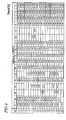
- compositions of the sintered bodies thus obtained were analyzed as shown in FIG. 4 . And the results shown in FIG. 4 were converted into the atomic percentages shown in FIG. 5 .
- the analysis was carried out using an ICP. However, the contents of oxygen, nitrogen and carbon were obtained with a gas analyzer. Each of these samples was subjected to a hydrogen analysis by a dissolution technique. As a result, the contents of hydrogen in those samples were in the range of 10 ppm to 20 ppm.
- the sintered bodies thus obtained were thermally treated at various temperatures for an hour within an Ar atmosphere and then cooled.
- the heat treatment was conducted with the temperatures changed according to the composition.
- some samples were subjected to the heat treatment up to three times with the temperatures changed. After those samples were machined, their magnetic properties were measured at room temperature with a B-H tracer. The magnetic properties of the same samples were measured again at 140 °C.
- Table 1 The results are shown in the following Table 1:
- Samples #13 through #18 represent comparative examples including less than 0.02 at% of Mn and had lower coercivity at 140 °C than Samples #1 through #12 of the present invention to which both Pr and Mn were added.
- Samples #19 and #20 also represent comparative examples to which either Pr or Nd was added as a rare-earth element. Compared to Sample #4 representing a specific example of the present invention (although the contents of the other elements are not equal to each other between these two samples), Sample #19 had lower coercivity at room temperature and Sample #20 had lower coercivity at 140 °C.
- Magnets of which the compositions were represented by Nd 13 .
- the results are shown in FIG. 3 .
- the magnets of this Example 2 were produced by the same method as that adopted for Example 1.
- Example 2 The same manufacturing process as that adopted for Example 1 was also carried out. Every magnet with any of these compositions was sintered at 1,020 °C for two hours. The magnetic properties were evaluated by calculating H k as an index and figuring out H k /H cJ as an index to loop squareness. In this case, H k represents a value of a demagnetization field when the value of magnetization becomes 90% of J r . The closer to one the H k /H cJ ratio is, the better the loop squareness and the more useful the given magnet should be.
- Sintered magnets with various compositions were obtained by the same method as that adopted for Example 1.
- the mole fraction of Mn added was fixed at 0.06 at%.
- As the additive elements M Al, Cu and Ga were selected from the first group and Mo was selected from the second group.
- the amounts of rare-earth elements, B and additive elements M were changed into various values (including zero).
- the compositions (analyzed values) of the magnets thus obtained are shown in the following Table 3 and their magnetic properties are shown in the following Table 4:
- a sintered magnet according to the present invention can be used extensively in various applications that require high-performance sintered magnets.
Applications Claiming Priority (1)
| Application Number | Priority Date | Filing Date | Title |
|---|---|---|---|
| PCT/JP2007/059384 WO2008139559A1 (ja) | 2007-05-02 | 2007-05-02 | R-t-b系焼結磁石 |
Publications (3)
| Publication Number | Publication Date |
|---|---|
| EP2034493A1 true EP2034493A1 (de) | 2009-03-11 |
| EP2034493A4 EP2034493A4 (de) | 2009-07-22 |
| EP2034493B1 EP2034493B1 (de) | 2012-12-05 |
Family
ID=39608107
Family Applications (1)
| Application Number | Title | Priority Date | Filing Date |
|---|---|---|---|
| EP07742819A Revoked EP2034493B1 (de) | 2007-05-02 | 2007-05-02 | R-t-b-sintermagnet |
Country Status (6)
| Country | Link |
|---|---|
| US (2) | US20080274009A1 (de) |
| EP (1) | EP2034493B1 (de) |
| JP (1) | JP4103937B1 (de) |
| KR (1) | KR101378090B1 (de) |
| CN (1) | CN101689416B (de) |
| WO (1) | WO2008139559A1 (de) |
Cited By (1)
| Publication number | Priority date | Publication date | Assignee | Title |
|---|---|---|---|---|
| EP2128290A1 (de) * | 2007-03-22 | 2009-12-02 | Showa Denko K.K. | R-t-b-legierung, herstellungsverfahren dafür, feinpulver für einen r-t-b-seltenerd-permanentmagneten und r-t-b-seltenerd-permanentmagnet |
Families Citing this family (25)
| Publication number | Priority date | Publication date | Assignee | Title |
|---|---|---|---|---|
| CN102067249B (zh) * | 2008-06-13 | 2014-07-30 | 日立金属株式会社 | R-T-Cu-Mn-B系烧结磁铁 |
| WO2010113465A1 (ja) * | 2009-03-31 | 2010-10-07 | 日立金属株式会社 | R-t-b-m系焼結磁石用合金及びその製造方法 |
| US20110074530A1 (en) * | 2009-09-30 | 2011-03-31 | General Electric Company | Mixed rare-earth permanent magnet and method of fabrication |
| JP5093215B2 (ja) * | 2009-11-26 | 2012-12-12 | トヨタ自動車株式会社 | 焼結希土類磁石の製造方法 |
| JP2011258935A (ja) * | 2010-05-14 | 2011-12-22 | Shin Etsu Chem Co Ltd | R−t−b系希土類焼結磁石 |
| CN101819841A (zh) * | 2010-05-17 | 2010-09-01 | 上海交通大学 | 钕铁硼磁性材料及其制备方法 |
| JP5692231B2 (ja) * | 2010-07-16 | 2015-04-01 | トヨタ自動車株式会社 | 希土類磁石の製造方法、及び希土類磁石 |
| JP4951703B2 (ja) | 2010-09-30 | 2012-06-13 | 昭和電工株式会社 | R−t−b系希土類永久磁石用合金材料、r−t−b系希土類永久磁石の製造方法およびモーター |
| EP2444985B1 (de) | 2010-10-25 | 2018-07-11 | Toyota Jidosha Kabushiki Kaisha | Herstellungsverfahren für Seltenerdmagneten |
| US8572830B2 (en) | 2011-03-14 | 2013-11-05 | Apple Inc. | Method and apparatus for producing magnetic attachment system |
| US9659260B2 (en) | 2011-03-15 | 2017-05-23 | Dan Caligor | Calendar based task and time management systems and methods |
| US9261236B2 (en) * | 2012-09-24 | 2016-02-16 | Elwha Llc | Train propellant management systems and methods |
| EP3790029A1 (de) | 2013-06-17 | 2021-03-10 | Urban Mining Technology Company, LLC | Magnetrecycling zur erzeugung von nd-fe-b-magneten mit verbesserter oder regenerierter magnetischer leistung |
| US9336932B1 (en) | 2014-08-15 | 2016-05-10 | Urban Mining Company | Grain boundary engineering |
| JP6672753B2 (ja) * | 2015-03-13 | 2020-03-25 | Tdk株式会社 | R−t−b系希土類焼結磁石及びr−t−b系希土類焼結磁石用合金 |
| US10428408B2 (en) | 2015-03-13 | 2019-10-01 | Tdk Corporation | R-T-B-based rare earth sintered magnet and alloy for R-T-B-based rare earth sintered magnet |
| DE112016002876T5 (de) * | 2015-06-25 | 2018-03-08 | Hitachi Metals Ltd. | R-T-B basierter Sintermagnet und Verfahren zu seiner Herstellung |
| JP6488976B2 (ja) * | 2015-10-07 | 2019-03-27 | Tdk株式会社 | R−t−b系焼結磁石 |
| JP6926861B2 (ja) * | 2017-09-08 | 2021-08-25 | Tdk株式会社 | R−t−b系永久磁石 |
| JP2019102707A (ja) * | 2017-12-05 | 2019-06-24 | Tdk株式会社 | R−t−b系永久磁石 |
| JP7251916B2 (ja) * | 2017-12-05 | 2023-04-04 | Tdk株式会社 | R-t-b系永久磁石 |
| JP2020161788A (ja) * | 2019-03-19 | 2020-10-01 | 日立金属株式会社 | R−t−b系焼結磁石 |
| CN110797157B (zh) * | 2019-11-21 | 2021-06-04 | 厦门钨业股份有限公司 | 钕铁硼磁体材料、原料组合物及制备方法和应用 |
| CN110828089B (zh) * | 2019-11-21 | 2021-03-26 | 厦门钨业股份有限公司 | 钕铁硼磁体材料、原料组合物及制备方法和应用 |
| CN115083714A (zh) | 2022-07-06 | 2022-09-20 | 烟台正海磁性材料股份有限公司 | 一种高矫顽力Nd-Fe-B系烧结磁体及其制备方法和应用 |
Citations (3)
| Publication number | Priority date | Publication date | Assignee | Title |
|---|---|---|---|---|
| US4917778A (en) * | 1989-05-26 | 1990-04-17 | Yugen Kaisha Johoku Riken Kogyo | Process for the corrosion protection of neodymium-iron-boron group sintered magnets |
| EP1705671A2 (de) * | 2005-03-23 | 2006-09-27 | Shin-Etsu Chemical Co., Ltd. | Seltenerd-Permanentmagnet |
| JP2006303436A (ja) * | 2005-03-23 | 2006-11-02 | Shin Etsu Chem Co Ltd | 希土類永久磁石 |
Family Cites Families (14)
| Publication number | Priority date | Publication date | Assignee | Title |
|---|---|---|---|---|
| US4792368A (en) * | 1982-08-21 | 1988-12-20 | Sumitomo Special Metals Co., Ltd. | Magnetic materials and permanent magnets |
| JPS5989401A (ja) | 1982-11-15 | 1984-05-23 | Sumitomo Special Metals Co Ltd | 永久磁石 |
| CA1316375C (en) * | 1982-08-21 | 1993-04-20 | Masato Sagawa | Magnetic materials and permanent magnets |
| JPS6034005A (ja) * | 1983-08-04 | 1985-02-21 | Sumitomo Special Metals Co Ltd | 永久磁石 |
| JPH066777B2 (ja) | 1985-07-24 | 1994-01-26 | 住友特殊金属株式会社 | 高性能永久磁石材料 |
| DE3783975T2 (de) | 1986-07-23 | 1993-05-27 | Hitachi Metals Ltd | Dauermagnet mit guter thermischer stabilitaet. |
| US4983232A (en) * | 1987-01-06 | 1991-01-08 | Hitachi Metals, Ltd. | Anisotropic magnetic powder and magnet thereof and method of producing same |
| US5227247A (en) * | 1989-06-13 | 1993-07-13 | Sps Technologies, Inc. | Magnetic materials |
| US5405455A (en) * | 1991-06-04 | 1995-04-11 | Shin-Etsu Chemical Co. Ltd. | Rare earth-based permanent magnet |
| JP4023138B2 (ja) * | 2001-02-07 | 2007-12-19 | 日立金属株式会社 | 鉄基希土類合金粉末および鉄基希土類合金粉末を含むコンパウンドならびにそれを用いた永久磁石 |
| US7014718B2 (en) * | 2001-09-03 | 2006-03-21 | Showa Denko K.K. | Rare earth magnet alloy ingot, manufacturing method for the same, R-T-B type magnet alloy ingot, R-T-B type magnet, R-T-B type bonded magnet, R-T-B type exchange spring magnet alloy ingot, R-T-B type exchange spring magnet, and R-T-B type exchange spring bonded magnet |
| JP4389427B2 (ja) * | 2002-02-05 | 2009-12-24 | 日立金属株式会社 | 希土類−鉄−硼素系磁石用合金粉末を用いた焼結磁石 |
| MY142024A (en) * | 2005-03-23 | 2010-08-16 | Shinetsu Chemical Co | Rare earth permanent magnet |
| JP4656323B2 (ja) * | 2006-04-14 | 2011-03-23 | 信越化学工業株式会社 | 希土類永久磁石材料の製造方法 |
-
2007
- 2007-05-02 WO PCT/JP2007/059384 patent/WO2008139559A1/ja active Application Filing
- 2007-05-02 CN CN2007800528152A patent/CN101689416B/zh active Active
- 2007-05-02 KR KR1020097023842A patent/KR101378090B1/ko active IP Right Grant
- 2007-05-02 EP EP07742819A patent/EP2034493B1/de not_active Revoked
- 2007-05-02 JP JP2007541537A patent/JP4103937B1/ja active Active
-
2008
- 2008-06-04 US US12/132,738 patent/US20080274009A1/en not_active Abandoned
-
2009
- 2009-09-18 US US12/562,336 patent/US7789933B2/en active Active
Patent Citations (3)
| Publication number | Priority date | Publication date | Assignee | Title |
|---|---|---|---|---|
| US4917778A (en) * | 1989-05-26 | 1990-04-17 | Yugen Kaisha Johoku Riken Kogyo | Process for the corrosion protection of neodymium-iron-boron group sintered magnets |
| EP1705671A2 (de) * | 2005-03-23 | 2006-09-27 | Shin-Etsu Chemical Co., Ltd. | Seltenerd-Permanentmagnet |
| JP2006303436A (ja) * | 2005-03-23 | 2006-11-02 | Shin Etsu Chem Co Ltd | 希土類永久磁石 |
Non-Patent Citations (1)
| Title |
|---|
| See also references of WO2008139559A1 * |
Cited By (2)
| Publication number | Priority date | Publication date | Assignee | Title |
|---|---|---|---|---|
| EP2128290A1 (de) * | 2007-03-22 | 2009-12-02 | Showa Denko K.K. | R-t-b-legierung, herstellungsverfahren dafür, feinpulver für einen r-t-b-seltenerd-permanentmagneten und r-t-b-seltenerd-permanentmagnet |
| EP2128290A4 (de) * | 2007-03-22 | 2010-12-01 | Showa Denko Kk | R-t-b-legierung, herstellungsverfahren dafür, feinpulver für einen r-t-b-seltenerd-permanentmagneten und r-t-b-seltenerd-permanentmagnet |
Also Published As
| Publication number | Publication date |
|---|---|
| CN101689416A (zh) | 2010-03-31 |
| WO2008139559A1 (ja) | 2008-11-20 |
| EP2034493A4 (de) | 2009-07-22 |
| US20080274009A1 (en) | 2008-11-06 |
| KR101378090B1 (ko) | 2014-03-27 |
| KR20100016577A (ko) | 2010-02-12 |
| US7789933B2 (en) | 2010-09-07 |
| JP4103937B1 (ja) | 2008-06-18 |
| JPWO2008139559A1 (ja) | 2010-07-29 |
| EP2034493B1 (de) | 2012-12-05 |
| US20100008814A1 (en) | 2010-01-14 |
| CN101689416B (zh) | 2012-10-03 |
Similar Documents
| Publication | Publication Date | Title |
|---|---|---|
| EP2034493B1 (de) | R-t-b-sintermagnet | |
| EP2077567B1 (de) | R-t-b-sintermagnet | |
| EP2388350B1 (de) | Verfahren zur herstellung eines gesinterten r-t-b-magneten | |
| EP1970916B1 (de) | R-fe-b poröser magnet und herstellungsverfahren dafür | |
| EP2302646B1 (de) | Sintermagnet des r-t-cu-mn-b-typs | |
| US8128758B2 (en) | R-Fe-B microcrystalline high-density magnet and process for production thereof | |
| JP5120710B2 (ja) | RL−RH−T−Mn−B系焼結磁石 | |
| US20130068992A1 (en) | Method for producing rare earth permanent magnets, and rare earth permanent magnets | |
| CN108417334B (zh) | R-t-b系烧结磁铁 | |
| CN109935432B (zh) | R-t-b系永久磁铁 | |
| US8182618B2 (en) | Rare earth sintered magnet and method for producing same | |
| CN112119475B (zh) | 稀土烧结永磁体的制造方法 | |
| JP4415374B2 (ja) | 希土類焼結磁石の製造方法 | |
| CN111755190A (zh) | R-t-b系永久磁铁用合金和r-t-b系永久磁铁的制造方法 | |
| Pourarian | Development of high performance permanent magnets based on Nd-Fe-B system |
Legal Events
| Date | Code | Title | Description |
|---|---|---|---|
| PUAI | Public reference made under article 153(3) epc to a published international application that has entered the european phase |
Free format text: ORIGINAL CODE: 0009012 |
|
| 17P | Request for examination filed |
Effective date: 20080609 |
|
| AK | Designated contracting states |
Kind code of ref document: A1 Designated state(s): AT BE BG CH CY CZ DE DK EE ES FI FR GB GR HU IE IS IT LI LT LU LV MC MT NL PL PT RO SE SI SK TR |
|
| AX | Request for extension of the european patent |
Extension state: AL BA HR MK RS |
|
| A4 | Supplementary search report drawn up and despatched |
Effective date: 20090618 |
|
| RIC1 | Information provided on ipc code assigned before grant |
Ipc: H01F 1/057 20060101AFI20090612BHEP Ipc: C22C 38/00 20060101ALI20081202BHEP Ipc: H01F 1/08 20060101ALI20081202BHEP |
|
| 17Q | First examination report despatched |
Effective date: 20100217 |
|
| GRAP | Despatch of communication of intention to grant a patent |
Free format text: ORIGINAL CODE: EPIDOSNIGR1 |
|
| DAX | Request for extension of the european patent (deleted) | ||
| GRAS | Grant fee paid |
Free format text: ORIGINAL CODE: EPIDOSNIGR3 |
|
| GRAA | (expected) grant |
Free format text: ORIGINAL CODE: 0009210 |
|
| AK | Designated contracting states |
Kind code of ref document: B1 Designated state(s): AT BE BG CH CY CZ DE DK EE ES FI FR GB GR HU IE IS IT LI LT LU LV MC MT NL PL PT RO SE SI SK TR |
|
| REG | Reference to a national code |
Ref country code: GB Ref legal event code: FG4D |
|
| REG | Reference to a national code |
Ref country code: CH Ref legal event code: EP |
|
| REG | Reference to a national code |
Ref country code: AT Ref legal event code: REF Ref document number: 587653 Country of ref document: AT Kind code of ref document: T Effective date: 20121215 |
|
| REG | Reference to a national code |
Ref country code: IE Ref legal event code: FG4D |
|
| REG | Reference to a national code |
Ref country code: NL Ref legal event code: T3 |
|
| REG | Reference to a national code |
Ref country code: DE Ref legal event code: R096 Ref document number: 602007027149 Country of ref document: DE Effective date: 20130131 |
|
| REG | Reference to a national code |
Ref country code: AT Ref legal event code: MK05 Ref document number: 587653 Country of ref document: AT Kind code of ref document: T Effective date: 20121205 |
|
| PG25 | Lapsed in a contracting state [announced via postgrant information from national office to epo] |
Ref country code: FI Free format text: LAPSE BECAUSE OF FAILURE TO SUBMIT A TRANSLATION OF THE DESCRIPTION OR TO PAY THE FEE WITHIN THE PRESCRIBED TIME-LIMIT Effective date: 20121205 Ref country code: ES Free format text: LAPSE BECAUSE OF FAILURE TO SUBMIT A TRANSLATION OF THE DESCRIPTION OR TO PAY THE FEE WITHIN THE PRESCRIBED TIME-LIMIT Effective date: 20130316 Ref country code: SE Free format text: LAPSE BECAUSE OF FAILURE TO SUBMIT A TRANSLATION OF THE DESCRIPTION OR TO PAY THE FEE WITHIN THE PRESCRIBED TIME-LIMIT Effective date: 20121205 Ref country code: LT Free format text: LAPSE BECAUSE OF FAILURE TO SUBMIT A TRANSLATION OF THE DESCRIPTION OR TO PAY THE FEE WITHIN THE PRESCRIBED TIME-LIMIT Effective date: 20121205 |
|
| REG | Reference to a national code |
Ref country code: LT Ref legal event code: MG4D |
|
| PG25 | Lapsed in a contracting state [announced via postgrant information from national office to epo] |
Ref country code: LV Free format text: LAPSE BECAUSE OF FAILURE TO SUBMIT A TRANSLATION OF THE DESCRIPTION OR TO PAY THE FEE WITHIN THE PRESCRIBED TIME-LIMIT Effective date: 20121205 Ref country code: PL Free format text: LAPSE BECAUSE OF FAILURE TO SUBMIT A TRANSLATION OF THE DESCRIPTION OR TO PAY THE FEE WITHIN THE PRESCRIBED TIME-LIMIT Effective date: 20121205 Ref country code: CY Free format text: LAPSE BECAUSE OF FAILURE TO SUBMIT A TRANSLATION OF THE DESCRIPTION OR TO PAY THE FEE WITHIN THE PRESCRIBED TIME-LIMIT Effective date: 20121205 Ref country code: GR Free format text: LAPSE BECAUSE OF FAILURE TO SUBMIT A TRANSLATION OF THE DESCRIPTION OR TO PAY THE FEE WITHIN THE PRESCRIBED TIME-LIMIT Effective date: 20130306 Ref country code: SI Free format text: LAPSE BECAUSE OF FAILURE TO SUBMIT A TRANSLATION OF THE DESCRIPTION OR TO PAY THE FEE WITHIN THE PRESCRIBED TIME-LIMIT Effective date: 20121205 |
|
| PG25 | Lapsed in a contracting state [announced via postgrant information from national office to epo] |
Ref country code: AT Free format text: LAPSE BECAUSE OF FAILURE TO SUBMIT A TRANSLATION OF THE DESCRIPTION OR TO PAY THE FEE WITHIN THE PRESCRIBED TIME-LIMIT Effective date: 20121205 |
|
| PG25 | Lapsed in a contracting state [announced via postgrant information from national office to epo] |
Ref country code: SK Free format text: LAPSE BECAUSE OF FAILURE TO SUBMIT A TRANSLATION OF THE DESCRIPTION OR TO PAY THE FEE WITHIN THE PRESCRIBED TIME-LIMIT Effective date: 20121205 Ref country code: EE Free format text: LAPSE BECAUSE OF FAILURE TO SUBMIT A TRANSLATION OF THE DESCRIPTION OR TO PAY THE FEE WITHIN THE PRESCRIBED TIME-LIMIT Effective date: 20121205 Ref country code: BG Free format text: LAPSE BECAUSE OF FAILURE TO SUBMIT A TRANSLATION OF THE DESCRIPTION OR TO PAY THE FEE WITHIN THE PRESCRIBED TIME-LIMIT Effective date: 20130305 Ref country code: IS Free format text: LAPSE BECAUSE OF FAILURE TO SUBMIT A TRANSLATION OF THE DESCRIPTION OR TO PAY THE FEE WITHIN THE PRESCRIBED TIME-LIMIT Effective date: 20130405 Ref country code: CZ Free format text: LAPSE BECAUSE OF FAILURE TO SUBMIT A TRANSLATION OF THE DESCRIPTION OR TO PAY THE FEE WITHIN THE PRESCRIBED TIME-LIMIT Effective date: 20121205 Ref country code: BE Free format text: LAPSE BECAUSE OF FAILURE TO SUBMIT A TRANSLATION OF THE DESCRIPTION OR TO PAY THE FEE WITHIN THE PRESCRIBED TIME-LIMIT Effective date: 20121205 |
|
| PG25 | Lapsed in a contracting state [announced via postgrant information from national office to epo] |
Ref country code: RO Free format text: LAPSE BECAUSE OF FAILURE TO SUBMIT A TRANSLATION OF THE DESCRIPTION OR TO PAY THE FEE WITHIN THE PRESCRIBED TIME-LIMIT Effective date: 20121205 Ref country code: PT Free format text: LAPSE BECAUSE OF FAILURE TO SUBMIT A TRANSLATION OF THE DESCRIPTION OR TO PAY THE FEE WITHIN THE PRESCRIBED TIME-LIMIT Effective date: 20130405 |
|
| PLBI | Opposition filed |
Free format text: ORIGINAL CODE: 0009260 |
|
| 26 | Opposition filed |
Opponent name: SIEMENS AKTIENGESELLSCHAFT Effective date: 20130826 |
|
| PLAX | Notice of opposition and request to file observation + time limit sent |
Free format text: ORIGINAL CODE: EPIDOSNOBS2 |
|
| PG25 | Lapsed in a contracting state [announced via postgrant information from national office to epo] |
Ref country code: DK Free format text: LAPSE BECAUSE OF FAILURE TO SUBMIT A TRANSLATION OF THE DESCRIPTION OR TO PAY THE FEE WITHIN THE PRESCRIBED TIME-LIMIT Effective date: 20121205 |
|
| REG | Reference to a national code |
Ref country code: DE Ref legal event code: R026 Ref document number: 602007027149 Country of ref document: DE Effective date: 20130826 |
|
| PG25 | Lapsed in a contracting state [announced via postgrant information from national office to epo] |
Ref country code: MC Free format text: LAPSE BECAUSE OF FAILURE TO SUBMIT A TRANSLATION OF THE DESCRIPTION OR TO PAY THE FEE WITHIN THE PRESCRIBED TIME-LIMIT Effective date: 20121205 Ref country code: IT Free format text: LAPSE BECAUSE OF FAILURE TO SUBMIT A TRANSLATION OF THE DESCRIPTION OR TO PAY THE FEE WITHIN THE PRESCRIBED TIME-LIMIT Effective date: 20121205 |
|
| REG | Reference to a national code |
Ref country code: CH Ref legal event code: PL |
|
| PG25 | Lapsed in a contracting state [announced via postgrant information from national office to epo] |
Ref country code: CH Free format text: LAPSE BECAUSE OF NON-PAYMENT OF DUE FEES Effective date: 20130531 Ref country code: LI Free format text: LAPSE BECAUSE OF NON-PAYMENT OF DUE FEES Effective date: 20130531 |
|
| PLBB | Reply of patent proprietor to notice(s) of opposition received |
Free format text: ORIGINAL CODE: EPIDOSNOBS3 |
|
| REG | Reference to a national code |
Ref country code: IE Ref legal event code: MM4A |
|
| PG25 | Lapsed in a contracting state [announced via postgrant information from national office to epo] |
Ref country code: IE Free format text: LAPSE BECAUSE OF NON-PAYMENT OF DUE FEES Effective date: 20130502 |
|
| PG25 | Lapsed in a contracting state [announced via postgrant information from national office to epo] |
Ref country code: MT Free format text: LAPSE BECAUSE OF FAILURE TO SUBMIT A TRANSLATION OF THE DESCRIPTION OR TO PAY THE FEE WITHIN THE PRESCRIBED TIME-LIMIT Effective date: 20121205 |
|
| PG25 | Lapsed in a contracting state [announced via postgrant information from national office to epo] |
Ref country code: TR Free format text: LAPSE BECAUSE OF FAILURE TO SUBMIT A TRANSLATION OF THE DESCRIPTION OR TO PAY THE FEE WITHIN THE PRESCRIBED TIME-LIMIT Effective date: 20121205 |
|
| PG25 | Lapsed in a contracting state [announced via postgrant information from national office to epo] |
Ref country code: LU Free format text: LAPSE BECAUSE OF NON-PAYMENT OF DUE FEES Effective date: 20130502 Ref country code: HU Free format text: LAPSE BECAUSE OF FAILURE TO SUBMIT A TRANSLATION OF THE DESCRIPTION OR TO PAY THE FEE WITHIN THE PRESCRIBED TIME-LIMIT; INVALID AB INITIO Effective date: 20070502 |
|
| RDAF | Communication despatched that patent is revoked |
Free format text: ORIGINAL CODE: EPIDOSNREV1 |
|
| REG | Reference to a national code |
Ref country code: FR Ref legal event code: PLFP Year of fee payment: 10 |
|
| APBM | Appeal reference recorded |
Free format text: ORIGINAL CODE: EPIDOSNREFNO |
|
| APBP | Date of receipt of notice of appeal recorded |
Free format text: ORIGINAL CODE: EPIDOSNNOA2O |
|
| APAH | Appeal reference modified |
Free format text: ORIGINAL CODE: EPIDOSCREFNO |
|
| APBQ | Date of receipt of statement of grounds of appeal recorded |
Free format text: ORIGINAL CODE: EPIDOSNNOA3O |
|
| APAH | Appeal reference modified |
Free format text: ORIGINAL CODE: EPIDOSCREFNO |
|
| RAP2 | Party data changed (patent owner data changed or rights of a patent transferred) |
Owner name: HITACHI METALS, LTD. |
|
| REG | Reference to a national code |
Ref country code: FR Ref legal event code: PLFP Year of fee payment: 11 |
|
| PLAB | Opposition data, opponent's data or that of the opponent's representative modified |
Free format text: ORIGINAL CODE: 0009299OPPO |
|
| R26 | Opposition filed (corrected) |
Opponent name: SIEMENS AKTIENGESELLSCHAFT Effective date: 20130826 |
|
| REG | Reference to a national code |
Ref country code: FR Ref legal event code: PLFP Year of fee payment: 12 |
|
| PGFP | Annual fee paid to national office [announced via postgrant information from national office to epo] |
Ref country code: NL Payment date: 20190412 Year of fee payment: 13 |
|
| PGFP | Annual fee paid to national office [announced via postgrant information from national office to epo] |
Ref country code: DE Payment date: 20190416 Year of fee payment: 13 |
|
| REG | Reference to a national code |
Ref country code: DE Ref legal event code: R064 Ref document number: 602007027149 Country of ref document: DE Ref country code: DE Ref legal event code: R103 Ref document number: 602007027149 Country of ref document: DE |
|
| APBU | Appeal procedure closed |
Free format text: ORIGINAL CODE: EPIDOSNNOA9O |
|
| PGFP | Annual fee paid to national office [announced via postgrant information from national office to epo] |
Ref country code: FR Payment date: 20190410 Year of fee payment: 13 |
|
| RDAG | Patent revoked |
Free format text: ORIGINAL CODE: 0009271 |
|
| STAA | Information on the status of an ep patent application or granted ep patent |
Free format text: STATUS: PATENT REVOKED |
|
| 27W | Patent revoked |
Effective date: 20190802 |
|
| GBPR | Gb: patent revoked under art. 102 of the ep convention designating the uk as contracting state |
Effective date: 20190802 |
|
| PGFP | Annual fee paid to national office [announced via postgrant information from national office to epo] |
Ref country code: GB Payment date: 20190501 Year of fee payment: 13 |