EP2030926A2 - Device for supporting a coiling spool containing a coiled strip of material - Google Patents
Device for supporting a coiling spool containing a coiled strip of material Download PDFInfo
- Publication number
- EP2030926A2 EP2030926A2 EP08155620A EP08155620A EP2030926A2 EP 2030926 A2 EP2030926 A2 EP 2030926A2 EP 08155620 A EP08155620 A EP 08155620A EP 08155620 A EP08155620 A EP 08155620A EP 2030926 A2 EP2030926 A2 EP 2030926A2
- Authority
- EP
- European Patent Office
- Prior art keywords
- winding
- roller
- winding shaft
- bearing
- supports
- Prior art date
- Legal status (The legal status is an assumption and is not a legal conclusion. Google has not performed a legal analysis and makes no representation as to the accuracy of the status listed.)
- Granted
Links
Images


Classifications
-
- B—PERFORMING OPERATIONS; TRANSPORTING
- B65—CONVEYING; PACKING; STORING; HANDLING THIN OR FILAMENTARY MATERIAL
- B65H—HANDLING THIN OR FILAMENTARY MATERIAL, e.g. SHEETS, WEBS, CABLES
- B65H19/00—Changing the web roll
- B65H19/22—Changing the web roll in winding mechanisms or in connection with winding operations
- B65H19/2238—The web roll being driven by a winding mechanism of the nip or tangential drive type
- B65H19/2253—The web roll being driven by a winding mechanism of the nip or tangential drive type and the roll being displaced during the winding operation
- B65H19/2261—Pope-roller
-
- B—PERFORMING OPERATIONS; TRANSPORTING
- B65—CONVEYING; PACKING; STORING; HANDLING THIN OR FILAMENTARY MATERIAL
- B65H—HANDLING THIN OR FILAMENTARY MATERIAL, e.g. SHEETS, WEBS, CABLES
- B65H2301/00—Handling processes for sheets or webs
- B65H2301/40—Type of handling process
- B65H2301/41—Winding, unwinding
- B65H2301/413—Supporting web roll
- B65H2301/41308—Releasably clamping the web roll shaft
-
- B—PERFORMING OPERATIONS; TRANSPORTING
- B65—CONVEYING; PACKING; STORING; HANDLING THIN OR FILAMENTARY MATERIAL
- B65H—HANDLING THIN OR FILAMENTARY MATERIAL, e.g. SHEETS, WEBS, CABLES
- B65H2402/00—Constructional details of the handling apparatus
- B65H2402/50—Machine elements
- B65H2402/52—Bearings, e.g. magnetic or hydrostatic bearings
-
- B—PERFORMING OPERATIONS; TRANSPORTING
- B65—CONVEYING; PACKING; STORING; HANDLING THIN OR FILAMENTARY MATERIAL
- B65H—HANDLING THIN OR FILAMENTARY MATERIAL, e.g. SHEETS, WEBS, CABLES
- B65H2408/00—Specific machines
- B65H2408/20—Specific machines for handling web(s)
- B65H2408/23—Winding machines
- B65H2408/236—Pope-winders with first winding on an arc of circle and secondary winding along rails
-
- B—PERFORMING OPERATIONS; TRANSPORTING
- B65—CONVEYING; PACKING; STORING; HANDLING THIN OR FILAMENTARY MATERIAL
- B65H—HANDLING THIN OR FILAMENTARY MATERIAL, e.g. SHEETS, WEBS, CABLES
- B65H2511/00—Dimensions; Position; Numbers; Identification; Occurrences
- B65H2511/10—Size; Dimensions
- B65H2511/12—Width
Definitions
- the invention relates to devices for receiving a wound material web having a winding bobbin according to the preamble of claim 1 or 2.
- Such a rewinder is out of the DE 102 97 181 T5 known.
- the two ends of the winding shaft or the bearing housings formed there are in this case supported in the winding receiving device on a support surface defining a carriage, which is guided along guides which are formed on a stationary support frame.
- Another rewinder is out of the EP 1 454 858 A1 known.
- the held between two roller arms of the rewinder core of the roll is drivable by means of drivable chuck and an engageable on the winding, non-driven, free-running application roller to ensure a bubble-free winding of the web.
- the distance between the roller arms is varied according to the length of the core.
- z. B Hard cardboard tubes of different lengths placed on the winding shaft
- the decorative pressure z. B widths of 1,850 mm, 2,070 mm and 2,200 mm.
- the Material web process due driven to fixed edge for example on the operating side of the machine, ie the side of the machine facing edge of the web has regardless of the width of the web always the same position.
- the arrangement winding roller / winding This asymmetry, in turn, can have negative effects on the winding quality, especially at high winding speeds, after the asymmetrically loaded winding shaft can deflect unbalanced.
- a rewinder for winding a material web onto a reel spool.
- a motor-driven winding roller is provided, to which the winding bobbin by means of a winding shaft can be adjusted.
- This rewinder has a pre-winding device arranged upstream of the winding receiving device.
- the winding shaft is mounted in the Vorwickel driven by means of rolling bearings.
- a guide rail for axial lateral guidance of the winding shaft in the pre-winding and in the winding receiving device is provided.
- the DE 1 013 295 A discloses an apparatus for receiving a wound coil having a wound material web having a plurality of winding shafts.
- the winding shafts are formed differently depending on the width of the material web.
- the DE 1 574 632 B , the DE 30 15 547 C2 , the DE 42 01 326 A1 , the DE 198 57 205 A1 , the US 3 411 734 A , the US 1 951 715 A , the US 2 270 806 A and the US 3,365,141 describe various embodiments of devices for winding webs of material.
- the invention has for its object to provide devices for receiving a wound material web having a winding spool.
- the achievable with the present invention consist in particular in that now the winding shaft, regardless of the width of the web or the length of the roll always at least substantially symmetrical and can be supported on both sides of the roll each close to the winding end, so that the deflection of the flexible winding shaft can always be reduced to a minimum and an asymmetry can be at least substantially avoided, which in total the winding quality can be improved.
- the rewinder comprises a machine frame 01, on which, inter alia, a plurality of rollers 02; 03; 04; 06; 07; 08; 09 are rotatably mounted, via which a material web 11,
- a printing material web 11 for example a paper web 11 or, for example, a film or laminated paper / aluminum foil of a reel spool 12, for example a hard cardboard tube 12, is supplied in order to be wound up into a reel 13.
- a roller 02 formed as an inlet roller 02, a guide roller 03, a guide roller 04, a measuring roller 06, a tension roller 07, a pendulum roller 08 and a winding roller 09; 03; 04; 06; 07; 08; 09 be provided.
- the draw roller 07 and the winding roller 09 can be driven by motor, for example by means of a servo motor. For rapid deceleration of the winding roller 09, this is provided at one of its axial ends with a brake disk 10.
- the web tension of the drawn-in material web 11 is regulated by suitable electronics by means of the draw roller 07, the pendulum roller 08 and the measuring roller 06.
- a perforator 14 may be incorporated.
- the trained as a hard cardboard tube 12 winding bobbin 12 is detachably mounted on a winding shaft 101 and is held there in a known per se and not shown manner.
- the winding shaft 101 together with reel spool 12 is employed in the winding operation against the motor-driven winding roller 09 under tension if necessary and thus driven by the winding roller 09, whereby the over the winding roller 09, through the gap between the winding roller 09 and reel spool 12 or reel 13 and the reel spool 12 being wound around web 11 is gradually wound up into a reel 13.
- the web tension and the contact pressure generate the required winding hardness of the individual winding layers to each other.
- the resulting winding 13 is supplied after reaching its final size of a lowering device 16, by means of the finished winding 13 is discharged from the winder, for example, to a transport device not shown for removal or further transport of the roll 13.
- the lowering device 16 can as shown two by means of a hydraulic device 17 pivotable pivot arms 18 which are connected to each other via a shaft 19 drivingly connected.
- the hollow winding spool 12 which may be formed as hard cardboard sleeve 12, may have an inner diameter of, for example 76 mm +/- 20% or an inner diameter of, for example, 150 mm +/- 20% and an axial length, for example between 500 and 5,000 mm, preferably between 1,500 and 3,000 mm, for example an axial length of 1,850 mm +/- 5% or of 2,200 mm +/- 5%.
- the rewinder is designed for the widest possible material web 11 or reel spool 12 and in the case of a narrower material web 11 or reel spool 12, the same, with respect to their length on the longest possible reel spool 12 designed winding shaft 101 is equipped with a correspondingly shorter reel spool 12.
- the clamping of the reel spool 12 or hard cardboard tube 12 on a winding shaft 101 can be done in a known per se and not shown manner, for example via jaws or clamping bars, which are incorporated in the winding shaft 101.
- the generation of the clamping force can be done for example via pneumatic, spring force or a mechanical threaded spindle with expanding jaws.
- the rewinder is designed for nonstop operation, i. H. it does not have to be stopped for the discharge of a full roll 13 and the feeding of a new winding shaft 101 equipped with a winding reel 12.
- the rewinder comprises a Vorwickel sensible 102, also called “Vorwickler” 102, which can accommodate a new, provided with a winding spool 12 winding shaft 101, while the previous winding 13 is still bespult, and further already a winding 13 a can produce certain initial size, as well as a winding receiving device 103, also called “Hauptwickler” 103, in which a partially wound up by the Vorwickler 102 and handed over winding 13 is finished.
- the pre-winder 102 comprises two swiveling arms 106 pivotable together by means of a pneumatic drive 104, for example, which pivot about the axis of the winding roller 09 are pivotable.
- the pivot arms 106 have at their free ends U-shaped recesses 107 for receiving and guiding a winding shaft 101, wherein a recorded in the pivot arms 106 winding shaft 101 herein by means of z.
- the main winder 103 likewise comprises two swiveling arms 111, which can be pivoted together by means of a pneumatic drive 114, for example, via a shaft 109 and which engage on the side wall sections 112; 113 of the machine frame 01 are pivotally mounted. Again, the free ends of the pivot arms 111 in approximately U-shaped recesses 116 which serve to receive and guide a winding shaft 101 in the main winder 103.
- the end sections of the winding shaft 101 lie in each case on one on the upper edge of the respective side wall section 112; 113 trained horizontal guide rail 117 and with increasing winding size of the winding 13 thus away from the winding roller 09 is displaceable, wherein the winding shaft 101 is guided in the pivot arms 111 and the required contact pressure to the winding roller 09 is maintained.
- a winding shaft 101 is inserted with an empty reel spool 12.
- an acceleration drive not shown, which engages with a gear of the winding shaft 101
- the winding shaft 101 is pre-accelerated to production speed.
- the winding shaft 101 and the reel spool 12 is pressed by means of the blank holder 108 against the winding roller 09 and the winding shaft 101 or reel spool 12 comes into contact with the web 11, for example, paper web 11.
- the acceleration drive now pivots and is switched off.
- the drive of the new winding shaft 101 is now carried out only by friction with the winding roller 09, wherein the contact pressure on the hold-108 is generated.
- the pivot arms 111 of the Feldwicklers 103 are at this time in a transfer position, as in Fig. 1 is shown. From a certain winding diameter, for example, 280 mm, the pivot arms 106 of the prewinder 102 begin to pivot down to the transfer position to the Hauptwickler 103.
- the preliminary winder 102 is in the transfer position to the main winder 103; in this phase, the U-shaped recess 107 of the pivot arms 106 of the prewinder 102 is parallel to the guide rail 117 of the Kleinwicklers 103, such as in this phase, the pivot arms 106 of the Vorwicklers 102 and the pivot arms 111 of the Hauptwicklers 103 this in Fig. 1 is shown, and the now underlying edge of the recess 107 is at the same height as the upper edge of the guide rail 117, so that the winding shaft 101 together with winding 13 with increasing winding diameter can now slide along the guide rail 117.
- the winding shaft 101 is now pressed by the main winder 103 to the winding roller 09.
- the contact pressure is controlled depending on the roll diameter of the roll 13.
- the hold-downs 108 of the pre-winder 102 are released in this operating phase and are open.
- the pre-winder 102 pivots back up into its loading position, so that a next winding shaft 101 together with the prepared reel spool 12 can be inserted into the pre-winder 102.
- the Hauptwickler 103 now pivots with increasing winding diameter in the direction of lowering device 16.
- the automatic roll change takes place as described above, wherein after adhering the material web 11 to the reel spool 12 of the next winding shaft 101st and the separation of the material web 11 of the main winder 103, the winding 13 of the lowering 16 supplies.
- the main winder 103 pivots back directly into its transfer position to the preliminary winder 102.
- the rewinder corresponds to the above rewinder in structure and function in large parts, so that reference can be made thereto.
- the formation of the provided winding shafts 21, the formed pre-winding device 22 or the preliminary winder 22, as well as the formed winding receiving device 23 or the main winder 23, which will be described below with reference to FIGS Fig. 3 to 11 will be explained in detail.
- Fig. 3 to 5 each show a winding receiving device 23 and a main winder 23, which receives a winding shaft 21 or 21a or 21 or 21b.
- the winding shaft 21 a according to Fig. 3 is different from the winding shaft 21 b according to Fig. 4 ,
- the winding shaft 21 a for receiving longer winding coils 12 and hard cardboard tubes 12 is formed as the winding shaft 21 b, as will be explained in more detail below.
- the main winder 23 comprises two carriers 24; 26, each having a support 27; 28 define for the winding shaft 21 a and 21 b.
- Each carrier 24; 26 is held on a support frame 29 and 31, respectively.
- At least one of the two support frames 29; 31 is in the direction of the axis of the winding shaft 21 a; 21 b adjustable formed, as indicated by the arrow A, which shows the adjustment direction.
- the support frame 31 is adjustable, while the support frame 29 is stationary.
- the support frame 29 may be adjustable, preferably both support frames 29; 31. However, due to the operation of the material web 11 on fixed edge, it is not predominantly adjusted.
- the stationary support frame 29 may in particular be arranged on the operating side of the machine, while the adjustable support frame 31 may be arranged on the drive side of the machine.
- a support 28 of the main winder 23 in the direction of the axis of the winding shaft 21 a; 21 b changeable and the other support 27 formed fixed in this direction.
- the adjustability of the support frame 29 and / or 31 can be accomplished, for example, that the corresponding support frame 29; 31 fixed at certain different positions on the machine frame 01, z. B. screwed, or that the support frame 29; 31 on parallel to the winding shaft 21 a; 21 b extending, fixed to the machine frame 01 guide rails is displaceable, possibly via a suitable motor drive, and can be locked in certain functional positions.
- winding shaft 21 a and 21 b in the region of the main winder 23 on both sides on supports 27; Stored 28 and the distance a of the two supports 27; 28 is corresponding to the width of the wound material web 11 and the space provided for this purpose Winding coil 12 formed changeable.
- the respective winding shaft 21 a; 21 b directly adjacent to the two ends of the winding coil used in each case 12 or immediately adjacent to the material web 11, close to the web edge to support or store, regardless of the respective width of the web 11 and the respective length of the reel spool 12th , so that the deflection of the flexible winding shaft 21 a; 21 b can always be reduced to a minimum and an asymmetry of the deflection can be at least substantially avoided, whereby the overall winding quality can be improved.
- the carriers 24; 26 are in a plane perpendicular to the axis of the winding shaft 21 a; 21 b movable, in particular rectilinearly movable, in particular clearance, arranged.
- the carriers 24; 26 movably guided on the respective support frame 29 and 31, in particular guided in a linearly displaceable manner, in the case of the embodiment in each case via a pair of guide rails 61; 62, on the respective support frame 29; 31 are attached, wherein on the carriers 24; 26 with the guide rails 61; 62 cooperating, not shown guide rollers can be stored.
- the two carriers 24; 26 are moved together or synchronously, which can be solved in a conventional manner, also not shown manner by mechanical or electronic means, and to drive the carrier 24; 26 may be provided, for example, a non-illustrated hydraulic drive.
- Fig. 3 shows the carriers 24; 26 of the main winder 23 in a first position, which may be a winding or winding shaft receiving position
- Fig. 5 shows the carriers 24; 26 in a second position, which may be a winding-dispensing position, for example, for delivery to a lowering device 16 (see. Fig. 1 and 2 ).
- Fig. 4 shows the carrier 24; 26 as in Fig. 3 again in its receiving position, but now with a zoom down to the stationary support frame 29 carrier frame 31 and thus one opposite Fig. 3 reduced distance a of the supports 27; 28 for operation of the rewinder with a winding spool 12 of smaller length or a material web 11 of smaller width, compared with the in Fig. 3 illustrated situation.
- the supports 27; 28, the carrier 24; 26 are each from one at the upper end of the carrier 24; 26 arranged bearing 32 in the form of a roller pair 32, consisting of two roller bearings rollers 32 '; 32 ", namely a spherical roller bearing pair 32 in steady rest, hereinafter called lunette bearing 32 formed, which in Fig. 6 again shown in side view.
- the rollers of the spherical roller bearing pair 32 are arranged at least substantially in a horizontal plane.
- the steady bearing 32 receives the weight forces of the roll 13 and allows the rotation of the roll thirteenth
- each steady rest bearing 32 is assigned a closing device 33 holding the winding shaft 21 in a functional position on the steady rest bearing 32.
- the locking device 33 thus takes over the securing of the roll 13 in the steady rest bearing 32 after the transfer from the preliminary winder 22 to the main winder 23.
- the closing device 33 may comprise a closing roller 36 which can be inserted between an opening position in which a winding shaft 21 in the steady rest bearing 32, and a closed position in which the closing roller 36, the winding shaft 21 in their Functional position in the steady rest bearing 32 secures, is movable.
- the closing roller 36 may be rotatably mounted on a movable, in particular pivotable arm 34, in particular at the end of a pivot arm 34, and z. B. hydraulically controlled to the winding shaft 21 and then roll on the winding shaft 21.
- the locking device 33 In its closed position, the locking device 33 is located above the two rollers of the spherical roller bearing pair 32 and between the two rollers in a 12 o'clock position, as in Fig. 6 shown.
- the winding shaft 21 is in the region of the supports 27; Thus each fixed in a three-point bearing, which three roller bearings rollers 32 '; 32 ", 36 has.
- the winding shafts 21 a; 21 b are formed differently depending on the width of the material web 11 and axial length of the reel spool 12, in particular, the bearing portions 37; 38, in particular winding receiving bearing portions 37; 38 or races 37; 38, with which the winding shafts 21 a; 21 b in the supports 27; 28 and the steady rest bearings 32 of the Hauptwicklers 23 rest, at least partially formed at different axial positions, corresponding to the respective distance a between the two supports 27; 28.
- Each length of a reel spool 12 is thus assigned a separate type of winding shaft, with correspondingly (at least partially) differently positioned bearing sections 37; 38 with a length of the corresponding reel spool 12 adapted bearing distance.
- the Wickalability-bearing portions 37; 38 of the winding shaft 21 may also be formed symmetrically.
- the support racks 29; 31 are depending on the length of the Winding spool 12 moved symmetrically.
- FIGS. 7 and 8 The in connection with the 3 and 4 used winding shafts 21 a and 21 b are in FIGS. 7 and 8 shown again.
- the bearing sections on the in 3 and 4 It can be seen that the bearing portions 37 on the operating side, regardless of the type of winding shaft, are preferably always arranged in a fixed axial position, namely at an end region of the winding shaft 21a; 21 b, so that the material web 11 or the winding 13 is always arranged with its one side as far as possible on the operating side, while the axial position of the bearing portions 38 varies.
- winding shaft type d. H. regardless of the respective different axial position of the bearing portion 38, all winding shafts 21 a; 21 b each have the same overall length, which simplifies in particular the handling and storage. This can also apply to "variable-width prewinders".
- the winding shafts 21 a; 21 b are formed so that they each have only as much clamping length or clamping jaws, as required for receiving a winding spool 12 of the respective length to be used, in other words, the length of the respective winding spool clamping portion 57 of the respective winding shafts 21 a; 21 b is the length of the winding coil 12 used in each case adapted.
- Winding shafts 21 a; 21 b are shown for two different winding widths, it is understood that more than two winding shaft types can be provided, corresponding to more than two winding shaft widths, z. B. three, four or even more winding shaft types, in which at least one of the two winding receiving bearing portions 37; 38 each in different axial position is formed and thus each different distances a between the winding receiving bearing portions 37; 38, but preferably all the same overall length.
- the rewinder according to the invention further comprises a pre-winder 22 and a pre-winder 22, respectively, which is similar in construction to the rewinder according to FIG Fig. 1 and 2 ,
- Fig. 9 shows a portion of the pre-winder 22 in its upwardly directed receiving position, together with a portion of a guide rail 39 of the main winder 23 and a guided therein end of a winding shaft 21 (shown for clarity without the associated winding 13).
- Fig. 10 shows the Vorwickler 22 in its downwardly pivoted transfer position to the Hauptwickler 23; to illustrate the operation of the winding shaft 21 is shown here in two different positions, each in turn without the associated winding thirteenth
- the pre-winder 22 comprises two mutually opposite, jointly by means of a not shown here, for example pneumatic drive, pivotable pivot arms 41 which are pivotable about the axis 42 of the winding roller 09. In the Fig. 9 to 11 only one of the two pivot arms 41 is shown.
- the two pivot arms 41 of the prewinder 22 are axially outside of the two carriers 24; 26 of the main winder 23 is arranged.
- the pivot arms 41 have at their free ends U-shaped recesses 43 for receiving and guiding a winding shaft 21, wherein a recorded in the pivot arms 41 winding shaft 21 herein by means of z.
- Each pivot arm 41 has an axially inwardly extending, seen in the axial direction of the winding shaft 21, in cross section U-shaped portion 46, in the various guide and bearing sections for guiding and supporting the winding shaft 21 are formed, as will become apparent from the following.
- the winding shaft 21 For supporting the winding shaft 21 in the pivot arms 41 of the preliminary winder 22, the winding shaft 21 comprises two bearing sections 47; 48, in particular Vorwickel-bearing sections 47; 48, which are assigned schwenkarm proposede bearing elements.
- the bearing distance between the two Vorwickel-bearing sections 47; 48 is always the same, irrespective of the type of winding shaft used, ie. H. the bearing sections 47; 48 are always at the same axial position of the winding shaft 21, regardless of the respective position of the winding receiving bearing portions 37; 39 according to different lengths of winding coils 12.
- the bearing distance can also be designed differently.
- the pre-winder 22 can also be made variable in width analogously to the main winder 23. This has the advantage that even then the winding shaft 21; 21a; 21 b in the pre-winder 22 can be received very close to the sleeve end or next to the paper web 11. As a result, in the case of very sensitive papers, the winding properties when winding the paper roll on the hard cardboard sleeve 12 can be improved because the bending of the winding shaft 21; 21a; 21 b can be reduced (wrinkling). For this it is not absolutely necessary that the winding shafts 21; 21a; 21 b of the different paper web widths then have different lengths in their total length. You just need to have another additional inner bearing for inclusion in the "variable width pre-winders".
- the pre-winder bearing sections 47 and 48 are located immediately adjacent to the winding receiving bearing sections 37 and 38, the support sections 52 (for hold-down 44) again directly adjacent thereto.
- the guide portion 53 remains in an existing position.
- the pre-winder 22 is then mechanically attached to the support racks 28; 31 attached and then moves automatically with their adjustment.
- the winding shaft 21 may in Vorwickler 22 in particular by means fixed to the winding shaft 21 bearings 47; Be stored 48, d. H.
- the pre-winding storage sections 47; 48 of the winding shaft 21 are preferably each of at least one rolling bearing 47; 48 formed at each of the two end portions of the winding shaft 21, wherein the rolling bearings 47; 48 as a ball bearing 47; 48 may be formed, in particular as deep groove ball bearings 47; 48th
- the winding shaft 21 is connected to the deep groove ball bearings 47; 48 in grooved linear guides 49 of the pivot arms 41 inserted, which are formed in the respective section 46, see. z. B. Fig. 9 ,
- the linear guides 49 are designed to be adjustable so that the play of the winding shafts 21 in the linear guide 49 of the preliminary winder 22 can be minimized.
- a winding shaft 21 is thus in the pivot arms 41 on the one hand via the roller bearings 47; 48 rotatably and on the other hand to adapt to winding on increasing winding diameter along the U-shaped recess 43 and the linear guide 49 slidably mounted.
- the example hydraulically or pneumatically controlled hold-down 44 is used to secure the winding shaft 21 in the recesses of the Vorwicklers 22 and for pressing the roll 13 to the winding roller 09 with the desired bias.
- Each swing arm 41 is assigned a hold-down 44.
- the hold-down 44 is between a release position in which the winding shaft 21 is released for loading or unloading, and a functional position in which the winding shaft 21 is held in the Vorwickel owned 22 in its operating position, movable, in particular formed pivotable.
- the hold-down 44 carries at its free end a roller 51 which rolls in the functional position of the blank holder 44 on the winding shaft 21.
- a support portion 52 is formed on both sides, which immediately adjacent to the respective Vorwickel-bearing portion 47; 48 is arranged, and Although in each case on the inner side, and the roller 51 is associated with a respective hold-down 44. With the hold-downs 44 in their functional position, their two rollers 51 thus roll on the two support sections 52 of the winding shaft 21.
- Vorwickler 22, Weinwickler 23 and winding shafts 21 thus leads to a system in which the Vorwickler 22 over all possible paper web widths has the maximum storage width, the Hauptwickler 23, however, always individually has a paper web width-dependent bearing width.
- the winding shafts 22 all have the same overall length and the same bearing sections 47; 48 for the pre-winder 22, but individually paper web width-dependent bearing portions 37 and / or 38 for the main winder 23rd
- the pre-winder 22 may be wide-variable.
- Each winding shaft 21 has on at least one of its two end portions a guide portion 53 for axially guiding the winding shaft 21 in the region of the preliminary winder 22 and / or the main winder 23.
- Each winding shaft 21 preferably has in each case a single guide section 53, which preferably faces the operating side of the machine.
- the guide section 53 is preferably designed as a radially projecting and / or recessed portion and, viewed in the axial direction, is arranged outside next to the pre-winding bearing section 47.
- the guide portion 53 may be formed as a cylindrical guide portion 53, in particular as a rolling bearing 53, for example as a ball bearing 53, in particular as deep groove ball bearings 53, and operates in the manner described below with machine-side guide means 58; 59 together.
- Each winding shaft 21 further has at one of its end portions, in particular the guide section 53 opposite end portion, a further functional portion 54 which, viewed in the axial direction outside of the Vorwickel-bearing portion 48 connects and may include a brake disc 55 and, for example, a pulse disc 56.
- the winding shafts 21; 21a; 21 b thus have seen in the axial direction of a first side, z.
- a guide portion 53 in a fixed position a Vorwickel-bearing portion 47 in a fixed position, a support portion 52 preferably immediately adjacent the Vorwickel-bearing portion 47th In a fixed position, a first winding receiving bearing portion 37 in a fixed position, a second winding receiving bearing portion 38 in a variable position corresponding to the respective winding shaft type, d. H.
- a further support portion 52 in fixed position a further support portion 52 in fixed position, another Vorwickel-bearing portion 48 preferably immediately adjacent to the support portion 52, and another functional portion 54 in a fixed position.
- a central winding coil clamping portion 57 is defined, in which the clamping elements not shown for fixing a winding spool 12 are arranged on the winding shaft 21.
- Fig. 9 to 11 show the interaction of the guide portion 53 of the winding shaft 21, which, as explained, as a rolling bearing 53, in particular as a deep groove ball bearing 53 may be formed with the machine-side guide means 58; 59.
- a guidance of the winding shaft 21 in the axial direction by means of the guide section 53 both in the pre-winder 22 and in the main winder 23.
- the guide section 53 is guided in a guide groove 58 in the section 46 of the pivot arm 41 whose width is adjustable is executed so that the allowable bearing clearance can be adjusted or adjusted.
- a guide rail 39 is provided, in which a guide groove 59 is likewise formed,
- the guide device 53; 58; 59 for the winding shaft 21 thus comprises a winding shaft side guide portion 53, for example in the form of a deep groove ball bearing 53 and a machine-side linear guide 58; 59, which includes a pre-winder-side linear guide section 58 and a main-winding-side linear guide section 59, the linear guide 58; 59 in the form of a guide shoulder, a guide groove 58; 59 o.
- the like. Can be formed.
Abstract
Description
Die Erfindung betrifft Vorrichtungen zur Aufnahme einer eine aufgewickelten Materialbahn aufweisenden Wickelspule gemäß dem Oberbegriff des Anspruchs 1 bzw. 2.The invention relates to devices for receiving a wound material web having a winding bobbin according to the preamble of
Ein solcher Aufwickler ist aus der
Ein weiterer Aufwickler ist aus der
Bei einem weiteren Aufwickler werden je nach Breite der Materialbahn Wickelspulen, z. B. Hartkartonhülsen unterschiedlicher Länge auf die Wickelwelle aufgesetzt, beim Dekordruck z. B. Breiten von 1.850 mm, 2.070 mm und 2.200 mm. Hierbei wird die Materialbahn verfahrensbedingt auf Festkante gefahren, beispielsweise auf der Bedienseite der Maschine, d. h. der dieser Seite der Maschine zugewandte Rand der Materialbahn hat unabhängig von der Breite der Materialbahn stets dieselbe Position. Hieraus wiederum folgt, dass bei kleineren Breiten der Materialbahn als der maximal verarbeitbaren Breite der Wickel stets außermittig in der Maschine gelagert ist, so dass sich eine Unsymmetrie bzgl. der Anordnung Wickelwalze/Wickel ergibt. Diese Unsymmetrie wiederum kann insbesondere bei hohen Wickelgeschwindigkeiten negative Einflüsse auf die Wickelqualität haben, nachdem sich die unsymmetrisch belastete Wickelwelle unsymmetrisch durchbiegen kann.In another rewinder, depending on the width of the web winding reels, z. B. Hard cardboard tubes of different lengths placed on the winding shaft, the decorative pressure z. B. widths of 1,850 mm, 2,070 mm and 2,200 mm. Here is the Material web process due driven to fixed edge, for example on the operating side of the machine, ie the side of the machine facing edge of the web has regardless of the width of the web always the same position. This in turn implies that at smaller widths of the web than the maximum processable width of the winding is always stored off-center in the machine, so that there is an imbalance with respect. The arrangement winding roller / winding. This asymmetry, in turn, can have negative effects on the winding quality, especially at high winding speeds, after the asymmetrically loaded winding shaft can deflect unbalanced.
Aus der
Die
Die
Der Erfindung liegt die Aufgabe zugrunde, Vorrichtungen zur Aufnahme einer eine aufgewickelten Materialbahn aufweisenden Wickelspule zu schaffen.The invention has for its object to provide devices for receiving a wound material web having a winding spool.
Die Aufgabe wird erfindungsgemäß durch die Merkmale des Anspruchs 1 bzw. 2 gelöst.The object is achieved by the features of
Die mit der Erfindung erzielbaren Vorteile bestehen insbesondere darin, dass nun die Wickelwelle unabhängig von der Breite der Materialbahn bzw. der Länge des Wickels stets zumindest im Wesentlichen symmetrisch und auf beiden Seiten des Wickels jeweils nahe am Wickelende unterstützt werden kann, so dass die Durchbiegung der biegeweichen Wickelwelle stets auf ein Minimum reduziert werden kann und eine Unsymmetrie zumindest im Wesentlichen vermieden werden kann, wodurch insgesamt die Wickelqualität verbessert werden kann.The achievable with the present invention consist in particular in that now the winding shaft, regardless of the width of the web or the length of the roll always at least substantially symmetrical and can be supported on both sides of the roll each close to the winding end, so that the deflection of the flexible winding shaft can always be reduced to a minimum and an asymmetry can be at least substantially avoided, which in total the winding quality can be improved.
Ausführungsbeispiele der Erfindung sind in den Zeichnungen dargestellt und werden im Folgenden näher beschrieben.Embodiments of the invention are illustrated in the drawings and will be described in more detail below.
- Fig. 1Fig. 1
- einen Aufwickler in perspektivischer Darstellung, mit einem teilweise gefüllten Wickel in einer Übergabeposition von einer Vorwickeleinrichtung zu einer Wickelaufnahmeeinrichtung;a rewinder in perspective view, with a partially filled winding in a transfer position of a Vorwickeleinrichtung to a winding receiving device;
- Fig. 2Fig. 2
-
den Aufwickler gemäß
Fig. 1 in Seitenansicht, mit einem an eine Absenkeinrichtung übergebenen vollen Wickel und einem in der Vorwickeleinrichtung befindlichen leeren Wickel;according to the rewinderFig. 1 in side view, with a handed over to a lowering full roll and located in the Vorwickeleinrichtung empty roll; - Fig. 3Fig. 3
- eine Wickelaufnahmeeinrichtung eines Aufwicklers mit einer Wickelwelle für eine erste Breite eines Wickels und den Trägern in einer Wickel-Aufnahmestellung;a winding receiving means of a winder with a winding shaft for a first width of a roll and the carriers in a winding receiving position;
- Fig. 4Fig. 4
-
die Wickelaufnahmeeinrichtung gemäß
Fig. 3 mit einer Wickelwelle für eine zweite Breite eines Wickels und den Trägern in einer Wickel-Aufnahmestellung;the winding receiving device according toFig. 3 with a winding shaft for a second width of a roll and the carriers in a winding receiving position; - Fig. 5Fig. 5
-
die Wickelaufnahmeeinrichtung gemäß
Fig. 3 mit den Trägern in einer Wickel-Abgabestellung;the winding receiving device according toFig. 3 with the carriers in a winding delivery position; - Fig. 6Fig. 6
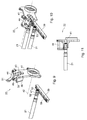
- eine Seitenansicht der Lagerung der Wickelwelle an den Trägern;a side view of the storage of the winding shaft to the carriers;
- Fig. 7Fig. 7
-
eine Seitenansicht einer Wickelwelle für eine erste Breite eines Wickels gemäß
Fig. 3 ;a side view of a winding shaft for a first width of a roll according toFig. 3 ; - Fig. 8Fig. 8
-
eine Seitenansicht einer Wickelwelle für eine zweite Breite eines Wickels gemäß
Fig. 4 ;a side view of a winding shaft for a second width of a roll according toFig. 4 ; - Fig. 9Fig. 9
- eine perspektivische Teilansicht einer Vorwickeleinrichtung eines Aufwicklers in einer Ladeposition;a partial perspective view of a Vorwickeleinrichtung a winder in a loading position;
- Fig. 10Fig. 10
-
die Vorwickeleinrichtung gemäß
Fig. 9 in Übergabeposition zur Wickelaufnahmeeinrichtung;the Vorwickeleinrichtung according toFig. 9 in transfer position to the winding receiving device; - Fig. 11Fig. 11
-
eine Seiten-Teilansicht der Vorwickeleinrichtung gemäß
Fig. 10 mit aufgenommener Wickelwelle.a side partial view of the Vorwickeleinrichtung according toFig. 10 with recorded winding shaft.
Zunächst wird auf
Der Aufwickler umfasst ein Maschinengestell 01, an welchem unter anderem mehrere Walzen 02; 03; 04; 06; 07; 08; 09 drehbar gelagert sind, über die eine Materialbahn 11, insbesondere eine Bedruckstoffbahn 11, beispielsweise eine Papierbahn 11 oder beispielsweise einer Folie oder kaschierten Papier/Alufolie einer Wickelspule 12, beispielsweise einer Hartkartonhülse 12 zugeführt wird, um zu einem Wickel 13 aufgewickelt zu werden. Im Einzelnen kann eine als Einlaufwalze 02, eine Leitwalze 03, eine Leitwalze 04, eine Messwalze 06, eine Zugwalze 07, eine Pendelwalze 08 sowie eine Wickelwalze 09 ausgebildete Walze 02; 03; 04; 06; 07; 08; 09 vorgesehen sein. Die Zugwalze 07 und die Wickelwalze 09 können motorisch beispielsweise mittels je eines Servomotors antreibbar sein. Zum raschen Abbremsen der Wickelwalze 09 ist diese an einem ihrer axialen Enden mit einer Bremsscheibe 10 versehen. Die Bahnspannung der eingezogenen Materialbahn 11 wird über eine geeignete Elektronik mittels der Zugwalze 07, der Pendelwalze 08 sowie der Messwalze 06 geregelt. Zur Unterstützung des Rollenwechsels kann eine Perforierungseinrichtung 14 eingebaut sein.The rewinder comprises a
Die beispielsweise als Hartkartonhülse 12 ausgebildete Wickelspule 12 ist lösbar auf eine Wickelwelle 101 aufgesetzt und wird dort in an sich bekannter und nicht näher dargestellter Weise gehalten. Die Wickelwelle 101 samt Wickelspule 12 wird im Aufwickelbetrieb gegen die motorisch angetriebene Wickelwalze 09 ggf. unter Vorspannung angestellt und somit von der Wickelwalze 09 angetrieben, wodurch die über die Wickelwalze 09, durch den Spalt zwischen Wickelwalze 09 und Wickelspule 12 bzw. Wickel 13 und um die Wickelspule 12 herum geführte Materialbahn 11 nach und nach zu einem Wickel 13 aufgewickelt wird. Die Bahnspannung und der Anpressdruck erzeugen dabei die erforderliche Wickelhärte der einzelnen Wickellagen zueinander.The trained as a
Der so entstehende Wickel 13 wird nach Erreichen seiner Endgröße einer Absenkeinrichtung 16 zugeführt, mittels der der fertige Wickel 13 vom Aufwickler abgegeben wird, beispielsweise an eine nicht näher dargestellte Transporteinrichtung zum Ab- bzw. Weitertransport des Wickels 13. Die Absenkeinrichtung 16 kann wie dargestellt zwei mittels einer Hydraulikeinrichtung 17 verschwenkbare Schwenkarme 18 umfassen, die über eine Welle 19 miteinander antriebsmäßig verbunden sind.The resulting
Die hohle Wickelspule 12, die als Hartkartonhülse 12 ausgebildet sein kann, kann einen Innendurchmesser von beispielsweise 76 mm +/- 20 % oder einen Innendurchmesser von beispielsweise 150 mm +/- 20 % aufweisen und eine axiale Länge beispielsweise zwischen 500 und 5.000 mm, vorzugsweise zwischen 1.500 und 3.000 mm, beispielsweise eine axiale Länge von 1.850 mm +/- 5 % oder von 2.200 mm +/- 5 %. Der Aufwickler ist für die breitest mögliche Materialbahn 11 bzw. Wickelspule 12 ausgelegt und im Falle einer schmäleren Materialbahn 11 bzw. Wickelspule 12 wird die gleiche, hinsichtlich ihrer Länge auf die längstmögliche Wickelspule 12 ausgelegte Wickelwelle 101 mit einer entsprechend kürzeren Wickelspule 12 bestückt.The
Das Spannen der Wickelspule 12 bzw. Hartkartonhülse 12 auf eine Wickelwelle 101 kann in an sich bekannter und nicht näher dargestellter Weise beispielsweise über Spannbacken oder Spannleisten erfolgen, die in die Wickelwelle 101 eingearbeitet sind. Die Erzeugung der Spannkraft kann beispielsweise über Pneumatik, Federkraft oder eine mechanische Gewindespindel mit Spreizbacken erfolgen.The clamping of the
Der Aufwickler ist für einen Nonstop-Betrieb ausgebildet, d. h. er muss für das Abführen eines vollen Wickels 13 und das Zuführen einer neuen, mit einer Wickelspule 12 ausgerüsteten Wickelwelle 101 nicht angehalten werden. Zu diesem Zweck umfasst der Aufwickler eine Vorwickeleinrichtung 102, auch "Vorwickler" 102 genannt, die eine neue, mit einer Wickelspule 12 versehene Wickelwelle 101 aufnehmen kann, während der vorhergehende Wickel 13 noch fertig bespult wird, und die des Weiteren bereits einen Wickel 13 einer bestimmten Anfangsgröße herstellen kann, sowie eine Wickelaufnahmeeinrichtung 103, auch "Hauptwickler" 103 genannt, in welcher ein vom Vorwickler 102 teilweise aufgespulter und übergebener Wickel 13 fertig gewickelt wird.The rewinder is designed for nonstop operation, i. H. it does not have to be stopped for the discharge of a
Der Vorwickler 102 umfasst zwei gemeinsam mittels eines beispielsweise pneumatischen Antriebs 104 verschwenkbare Schwenkarme 106, die um die Achse der Wickelwalze 09 verschwenkbar sind. Die Schwenkarme 106 weisen an ihren freien Enden U-förmige Ausnehmungen 107 zur Aufnahme und Führung einer Wickelwelle 101 auf, wobei eine in den Schwenkarmen 106 aufgenommene Wickelwelle 101 hierin mittels z. B. pneumatisch gesteuerter Niederhalter 108 gehalten und mit der gewünschten Kraft in Richtung Wickelwalze 09 gedrückt wird.The pre-winder 102 comprises two swiveling
Der Hauptwickler 103 umfasst ebenfalls zwei mittels eines beispielsweise pneumatischen Antriebs 114 über eine Welle 109 gemeinsam verschwenkbare Schwenkarme 111, die an den Seitenwandabschnitten 112; 113 des Maschinengestells 01 verschwenkbar gelagert sind. Wiederum weisen die freien Enden der Schwenkarme 111 in etwa U-förmige Ausnehmungen 116 auf, die zur Aufnahme und Führung einer Wickelwelle 101 im Hauptwickler 103 dienen. Im Bereich des Hauptwicklers 103 liegen die Endabschnitte der Wickelwelle 101 jeweils auf einer auf der Oberkante des jeweiligen Seitenwandabschnitts 112; 113 ausgebildeten waagrechten Führungsschiene 117 auf und mit zunehmender Wickelgröße ist der Wickel 13 somit weg von der Wickelwalze 09 verschiebbar, wobei die Wickelwelle 101 in den Schwenkarmen 111 geführt ist und hierüber der erforderliche Anpressdruck an die Wickelwalze 09 aufrechterhalten wird.The
Ein automatischer Wickelwechsel während der Produktion geht im Falle der hier beschriebenen Ausführungsform des Aufwicklers im Wesentlichen wie folgt vonstatten:In the case of the embodiment of the rewinder described here, an automatic reel change during production essentially takes place as follows:
In den mit seiner U-förmigen Ausnehmung 107 nach oben weisenden Vorwickler 102 ist eine Wickelwelle 101 mit leerer Wickelspule 12 eingelegt. Mittels eines nicht näher dargestellten Beschleunigungsantriebs, der mit einem Zahnrad der Wickelwelle 101 in Eingriff kommt, wird die Wickelwelle 101 auf Produktionsgeschwindigkeit vorbeschleunigt. Die Wickelwelle 101 bzw. die Wickelspule 12 wird mittels des Niederhalters 108 gegen die Wickelwalze 09 gedrückt und die Wickelwelle 101 bzw. Wickelspule 12 kommt in Kontakt mit der Materialbahn 11, beispielsweise Papierbahn 11. Sobald die Papierbahn 11 in Kontakt mit einer vorbereiteten Klebestelle auf der Wickelspule 12 kommt, reißt die Papierbahn 11 zwischen dem vorhergehenden, vollständig aufgewickelten Wickel 13 und der Klebestelle ab.In the with its
Der Beschleunigungsantrieb schwenkt nun ab und wird ausgeschaltet. Der Antrieb der neuen Wickelwelle 101 erfolgt jetzt nur noch durch Friktion mit der Wickelwalze 09, wobei der Anpressdruck über den Niederhalter 108 erzeugt wird.The acceleration drive now pivots and is switched off. The drive of the new winding
Die Schwenkarme 111 des Hauptwicklers 103 stehen zu diesem Zeitpunkt in einer Übergabeposition, wie sie in
Die Wickelwelle 101 wird nun durch den Hauptwickler 103 an die Wickelwalze 09 gepresst. Der Anpressdruck wird abhängig vom Rollendurchmesser des Wickels 13 gesteuert. Die Niederhalter 108 des Vorwicklers 102 werden in dieser Betriebsphase gelöst und sind geöffnet. Bei einem bestimmten Wickeldurchmesser, beispielsweise bei 430 mm, schwenkt der Vorwickler 102 wieder zurück nach oben in seine Ladestellung, so dass eine nächste Wickelwelle 101 samt vorbereiteter Wickelspule 12 in den Vorwickler 102 eingesetzt werden kann.The winding
Der Hauptwickler 103 schwenkt nun mit zunehmendem Wickeldurchmesser in Richtung Absenkvorrichtung 16. Beim Erreichen eines vorbestimmtem Wickeldurchmessers bzw. einer vorbestimmten Länge der aufgewickelten Materialbahn 11 erfolgt der automatische Wickelwechsel wie vorstehend beschrieben, wobei nach dem Ankleben der Materialbahn 11 an die Wickelspule 12 der nächsten Wickelwelle 101 und dem Abtrennen der Materialbahn 11 der Hauptwickler 103 den Wickel 13 der Absenkeinrichtung 16 zuführt. Nachdem der Hauptwickler 103 seine Übergabeposition zur Absenkeinrichtung 16 erreicht hat, schwenkt der Hauptwickler 103 direkt in seine Übergabeposition zum Vorwickler 102 zurück.The
Der auf der Absenkeinrichtung 16 aufliegende Wickel 13 befindet sich noch in Rotation und wird nun mittels einer nicht näher dargestellten Hydraulikbremse, die auf eine an einem axialen Ende der Wickelwelle 101 befestigte Bremsscheibe 118 einwirkt, zum Stillstand gebracht. Sobald der Wickel 13 zum Stillstand gekommen ist, kann er durch manuelles Betätigen eines am Maschinenleitstand 20 ausgebildeten Drucktasters mittels der Absenkeinrichtung 16 abgesenkt werden, die nach Entnahme der Wickels 13 durch Betätigen des genannten Drucktasters dann wieder in ihre Übergabestellung zurückgeschwenkt wird.The resting on the
Der Aufwickler entspricht dem vorstehenden Aufwickler in Aufbau und Funktion in großen Teilen, so dass hierauf Bezug genommen werden kann. Unterschiedlich sind jedoch insbesondere die Ausbildung der vorgesehenen Wickelwellen 21, der ausgebildeten Vorwickeleinrichtung 22 bzw. des Vorwicklers 22, sowie der ausgebildeten Wickelaufnahmeeinrichtung 23 bzw. des Hauptwicklers 23, die im Folgenden unter Bezugnahme auf die
Der Hauptwickler 23 umfasst zwei Träger 24; 26, die jeweils ein Auflager 27; 28 für die Wickelwelle 21 a bzw. 21 b definieren. Jeder Träger 24; 26 ist an einem Trägergestell 29 bzw. 31 gehalten. Zumindest eines der beiden Trägergestelle 29; 31 ist in Richtung der Achse der Wickelwelle 21 a; 21 b verstellbar ausgebildet, wie durch den Pfeil A, der die Verstellrichtung zeigt, angedeutet ist. Im Falle des beschriebenen Ausführungsbeispiels ist das Trägergestell 31 verstellbar ausgebildet, während das Trägergestell 29 ortsfest ist. Auch kann das Trägergestell 29 verstellbar sein, vorzugsweise beide Trägergestelle 29; 31. Es wird aber bedingt durch das Betreiben der Materialbahn 11 auf Festkante überwiegend nicht verstellt. Das ortsfeste Trägergestell 29 kann insbesondere an der Bedienseite der Maschine angeordnet sein, während das verstellbare Trägergestell 31 an der Antriebsseite der Maschine angeordnet sein kann. Somit ist im Falle des Ausführungsbeispiels ein Auflager 28 des Hauptwicklers 23 in Richtung der Achse der Wickelwelle 21 a; 21 b ortsveränderbar und das andere Auflager 27 in dieser Richtung feststehend ausgebildet.The
Die Verstellbarkeit des Trägergestells 29 und/oder 31 kann beispielsweise dadurch bewerkstelligt werden, dass das entsprechende Trägergestell 29; 31 an bestimmten unterschiedlichen Positionen am Maschinengestell 01 fixierbar, z. B. verschraubbar ist, oder dass das Trägergestell 29; 31 auf parallel zur Wickelwelle 21 a; 21 b verlaufenden, am Maschinengestell 01 befestigten Führungsschienen verschiebbar ist, ggf. über einen geeigneten motorischen Antrieb, und in bestimmten Funktionspositionen arretierbar ist.The adjustability of the
Somit ist die Wickelwelle 21 a bzw. 21 b im Bereich des Hauptwicklers 23 beidseitig auf Auflagern 27; 28 gelagert und der Abstand a der beiden Auflager 27; 28 ist entsprechend der Breite der aufzuwickelnden Materialbahn 11 bzw. der hierfür vorgesehenen Wickelspule 12 veränderbar ausgebildet. Durch die Veränderbarkeit des gegenseitigen Abstandes a der Auflager 27; 28 ist es möglich, die jeweilige Wickelwelle 21 a; 21 b unmittelbar neben den beiden Enden der jeweils verwendeten Wickelspule 12 bzw. unmittelbar neben der Materialbahn 11, eng an der Bahnkante, zu unterstützen bzw. zu lagern, und zwar unabhängig von der jeweiligen Breite der Materialbahn 11 bzw. der jeweiligen Länge der Wickelspule 12, so dass die Durchbiegung der biegeweichen Wickelwelle 21 a; 21 b stets auf ein Minimum reduziert werden kann und eine Unsymmetrie der Durchbiegung zumindest im Wesentlichen vermieden werden kann, wodurch insgesamt die Wickelqualität verbessert werden kann.Thus, the winding
Die Träger 24; 26 sind in einer Ebene senkrecht zur Achse der Wickelwelle 21 a; 21 b beweglich, insbesondere geradlinig beweglich, insbesondere spielfrei, angeordnet. Zu diesem Zweck sind die Träger 24; 26 am jeweiligen Trägergestell 29 bzw. 31 beweglich geführt, insbesondere geradlinig verschieblich geführt, im Falle des Ausführungsbeispiels jeweils über ein Paar von Führungsschienen 61; 62, die am jeweiligen Trägergestell 29; 31 befestigt sind, wobei an den Trägern 24; 26 mit den Führungsschienen 61; 62 zusammenwirkende, nicht näher dargestellte Führungsrollen gelagert sein können. Die beiden Träger 24; 26 werden gemeinsam bzw. synchron bewegt, was in an sich bekannter, ebenfalls nicht näher dargestellter Weise mit mechanischen oder elektronischen Mitteln gelöst werden kann, und zum Antrieb der Träger 24; 26 kann beispielsweise ein nicht näher dargestellter hydraulischer Antrieb vorgesehen sein.The
Während im Vorstehenden nur zwei unterschiedliche Abstandspositionen der Auflager 27; 28 bzw. der Träger 24; 26 bzw. der Trägergestelle 29; 31 beschrieben und in der Zeichnung dargestellt wurden, entsprechend zwei unterschiedlichen Breiten der Materialbahn 11, versteht es sich, dass mehrere unterschiedliche Abstandspositionen möglich sind, grundsätzlich beliebig viele Abstandspositionen entsprechend beliebig vielen Abstandspositionen der Träger 24; 26 bzw. der Trägergestelle 29; 31.While in the foregoing only two different distance positions of the
Die Auflager 27; 28 der Träger 24; 26 werden jeweils von einem am oberen Ende des Trägers 24; 26 angeordneten Lager 32 in Form eines Rollenpaars 32, bestehend aus zwei wälzgelagerten Rollen 32'; 32", nämlich einem Pendelrollenlagerpaar 32 in Lünettenform, im folgenden Lünetten-Lager 32 genannt, gebildet, welches in
Damit die Wickelwelle 21 unter der Wirkung der Anstellkraft des Hauptwicklers 23 an die Wickelwalze 09 nicht aus den Lünetten-Lagern 32 springt, ist jedem Lünetten-Lager 32 eine die Wickelwelle 21 in Funktionsposition auf dem Lünetten-Lager 32 haltende Schließeinrichtung 33 zugeordnet. Die Schließeinrichtung 33 übernimmt somit die Sicherung des Wickels 13 im Lünetten-Lager 32 nach der Übergabe vom Vorwickler 22 zum Hauptwickler 23.So that the winding
Die Schließeinrichtung 33 kann eine Schließrolle 36 umfassen, die zwischen einer Öffnungsposition, in der eine Wickelwelle 21 in das Lünetten-Lager 32 einlegbar ist, und einer Schließposition, in der die Schließrolle 36 die Wickelwelle 21 in ihrer Funktionsposition im Lünetten-Lager 32 sichert, bewegbar ist. Die Schließrolle 36 kann auf einem bewegbaren, insbesondere verschwenkbaren Arm 34 drehbar gelagert sein, insbesondere am Ende eines Schwenkarms 34, und z. B. hydraulisch gesteuert an die Wickelwelle 21 anstellbar sein und dann auf der Wickelwelle 21 abrollen. In ihrer Schließposition befindet sich die Schließeinrichtung 33 oberhalb der beiden Rollen des Pendelrollenlagerpaars 32 und zwischen den beiden Rollen in einer 12-Uhr-Position, wie in
Durch die Verwendung der beschriebenen Lünetten-Lager 32 entsteht der weitere Vorteil, dass die bislang üblicherweise verwendeten Festloslager, die auf der Wickelwelle 101 erforderlich sind, um diese zu lagern, entfallen. Diese Lagerschalen erschweren das Handling der Wickelwellen 101 und erhöhen deren Gewicht.By using the described
Wie weiter oben beschrieben ist der Abstand a zwischen den beiden Auflagern 27; 28 je nach Bahnbreite bzw. Länge der jeweils verwendeten Wickelspule 12 variabel. Die Wickelwellen 21 a; 21 b sind je nach Breite der Materialbahn 11 bzw. axialer Länge der Wickelspule 12 unterschiedlich ausgebildet, insbesondere sind die Lagerabschnitte 37; 38, insbesondere Wickelaufnahme-Lagerabschnitte 37; 38 oder Laufringe 37; 38, mit denen die Wickelwellen 21 a; 21 b in den Auflagern 27; 28 bzw. den Lünetten-Lagern 32 des Hauptwicklers 23 aufliegen, zumindest teilweise an unterschiedlichen axialen Positionen ausgebildet, entsprechend dem jeweiligen Abstand a zwischen den beiden Auflagern 27; 28. Jeder Länge einer Wickelspule 12 ist somit ein eigener Wickelwellentypus zugeordnet, mit entsprechend (zumindest teilweise) unterschiedlich positionierten Lagerabschnitten 37; 38 mit einem der Länge der entsprechenden Wickelspule 12 angepasstem Lagerabstand.As described above, the distance a between the two
Die Wickalaufnahme-Lagerabschnitte 37; 38 der Wickelwelle 21 können auch symmetrisch ausgebildet sein. Die Trägergestelle 29; 31 werden je nach Länge der Wickelspule 12 symmetrisch verfahren.The Wickalaufnahme-bearing
Die im Zusammenhang mit den
Vorzugsweise ist des Weiteren vorgesehen, dass unabhängig vom Wickelwellentypus, d. h. unabhängig von der jeweils unterschiedlichen axialen Position des Lagerabschnitts 38, alle Wickelwellen 21 a; 21 b jeweils die gleiche Gesamtlänge aufweisen, was insbesondere das Handling und die Lagerhaltung vereinfacht. Dies kann auch bei "breitenvariablen Vorwicklern" gelten.Preferably, it is further provided that regardless of the winding shaft type, d. H. regardless of the respective different axial position of the bearing
Die Wickelwellen 21 a; 21 b sind so ausgebildet, dass sie jeweils nur so viel Spannlänge bzw. Spannbacken aufweisen, wie für die Aufnahme einer Wickelspule 12 der jeweils einzusetzenden Länge erforderlich ist, in anderen Worten, die Länge des jeweiligen Wickelspulen-Spannabschnitts 57 der jeweiligen Wickelwellen 21 a; 21 b ist der Länge der jeweils verwendeten Wickelspule 12 angepasst.The winding
Während in den
Der Aufwickler gemäß der Erfindung umfasst des Weiteren eine Vorwickeleinrichtung 22 bzw. einen Vorwickler 22, der ähnlich ausgebildet ist wie im Falle des Aufwicklers gemäß
Der Vorwickler 22 umfasst zwei einander gegenüberliegende, gemeinsam mittels eines hier nicht näher dargestellten, beispielsweise pneumatischen Antriebs, verschwenkbare Schwenkarme 41, die um die Achse 42 der Wickelwalze 09 verschwenkbar sind. In den
Die Schwenkarme 41 weisen an ihren freien Enden U-förmige Ausnehmungen 43 zur Aufnahme und Führung einer Wickelwelle 21 auf, wobei eine in den Schwenkarmen 41 aufgenommene Wickelwelle 21 hierin mittels z. B. pneumatisch gesteuerter Niederhalter 44 gehalten und mit der gewünschten Kraft in Richtung Wickelwalze 09 gedrückt wird.The
Jeder Schwenkarm 41 weist einen sich in axialer Richtung der Wickelwelle 21 gesehen axial nach innen erstreckenden, im Querschnitt U-förmigen Abschnitt 46 auf, in dem verschiedene Führungs- und Lagerabschnitte zur Führung und Lagerung der Wickelwelle 21 ausgebildet sind, wie aus dem Folgenden deutlich werden wird.Each
Zur Lagerung der Wickelwelle 21 in den Schwenkarmen 41 des Vorwicklers 22 umfasst die Wickelwelle 21 zwei Lagerabschnitte 47; 48, insbesondere Vorwickel-Lagerabschnitte 47; 48, denen schwenkarmseitige Lagerelemente zugeordnet sind. Der Lagerabstand zwischen den beiden Vorwickel-Lagerabschnitten 47; 48 ist unabhängig vom jeweiligen Wickelwellen-Typus immer gleich, d. h. die Lagerabschnitte 47; 48 befinden sich stets an der gleichen axialen Position der Wickelwelle 21, unabhängig von der jeweiligen Position der Wickelaufnahme-Lagerabschnitte 37; 39 entsprechend unterschiedlich langen Wickelspulen 12. Bei einem breitenvariablen Vorwickler, kann der Lagerabstand auch unterschiedlich ausgebildet sein.For supporting the winding
Der Vorwickler 22 kann aber auch analog zum Hauptwickler 23 breitenvariabel ausgeführt werden. Dies hat den Vorteil, dass auch dann die Wickelwelle 21; 21 a; 21 b im Vorwickler 22 sehr nahe am Hülsenende bzw. neben der Papierbahn 11 aufgenommen werden kann. Dadurch können sich bei sehr empfindlichen Papieren die Wickeleigenschaften beim Anwickeln der Papierrolle auf der Hartkartonhülse 12 verbessern da die Durchbiegung der Wickelwelle 21; 21 a; 21 b reduziert werden kann (Faltenbildung). Dazu ist es nicht zwingend erforderlich, dass die Wickelwellen 21; 21 a; 21 b der unterschiedlichen Papierbahnbreiten dann auch in ihrer Gesamtlänge unterschiedlich lang sind. Sie müssen nur eine weitere zusätzliche Innenlagerung zur Aufnahme im "breitenvariablen Vorwickler" besitzen. D. h. die Vorwickler-Lagerabschnitte 47 und 48 werden unmittelbar neben die Wickelaufnahme-Lagerabschnitte 37 und 38 angeordnet, die Stützabschnitte 52 (für Niederhalter 44) wieder direkt daneben. Der Führungsabschnitt 53 bleibt in vorhandener Position. Der Vorwickler 22 wird dann mechanisch an den Trägergestellen 28; 31 befestigt und fährt dann automatisch bei deren Verstellung mit.However, the pre-winder 22 can also be made variable in width analogously to the
Die Position der Bremsscheibe und des Beschleunigungsantriebs bleibt auf der gleichen Spur des festen Vorwicklers vorhanden. Somit kann die Gesamtlänge der unterschiedlichen Wickelwellen gleich bleiben.The position of the brake disc and the acceleration drive remains on the same track of the fixed pre-winder. Thus, the total length of the different winding shafts remain the same.
Die Wickelwelle 21 kann im Vorwickler 22 insbesondere mittels auf der Wickelwelle 21 fixierter Wälzlager 47; 48 gelagert sein, d. h. die Vorwickel-Lagerabschnitte 47; 48 der Wickelwelle 21 werden vorzugsweise von jeweils mindestens einem Wälzlager 47; 48 an jedem der beiden Endabschnitte der Wickelwelle 21 gebildet, wobei die Wälzlager 47; 48 als Kugellager 47; 48 ausgebildet sein können, insbesondere als Rillenkugellager 47; 48.The winding
Die Wickelwelle 21 wird mit den Rillenkugellagern 47; 48 in genutete Linearführungen 49 der Schwenkarme 41 eingelegt, die im jeweiligen Abschnitt 46 ausgebildet sind, vgl. z. B.
Der beispielsweise hydraulisch oder pneumatisch gesteuerte Niederhalter 44 dient zum Sichern der Wickelwelle 21 in den Ausnehmungen des Vorwicklers 22 und zum Andrücken des Wickels 13 an die Wickelwalze 09 mit der gewünschten Vorspannung. Jedem Schwenkarm 41 ist ein Niederhalter 44 zugeordnet. Der Niederhalter 44 ist zwischen einer Freigabeposition, in der die Wickelwelle 21 zum Be- oder Entladen freigegeben wird, und einer Funktionsposition, in der die Wickelwelle 21 in der Vorwickeleinrichtung 22 in ihrer Funktionsposition gehalten wird, bewegbar, insbesondere verschwenkbar ausgebildet. Der Niederhalter 44 trägt an seinem freien Ende eine Rolle 51, die in Funktionsposition des Niederhalters 44 auf der Wickelwelle 21 abrollt.The example hydraulically or pneumatically controlled hold-down 44 is used to secure the winding
Auf der Wickelwelle 21 ist beidseitig jeweils ein Stützabschnitt 52 ausgebildet, der unmittelbar neben dem jeweiligen Vorwickel-Lagerabschnitt 47; 48 angeordnet ist, und zwar jeweils auf der innenliegenden Seite, und der der Rolle 51 jeweils eines Niederhalters 44 zugeordnet ist. Bei in Funktionsposition befindlichen Niederhaltern 44 rollen somit deren beide Rollen 51 auf den beiden Stützabschnitten 52 der Wickelwelle 21 ab.On the winding
Die beschriebene Ausbildung von Vorwickler 22, Hauptwickler 23 und Wickelwellen 21 führt somit zu einem System, bei dem bei dem der Vorwickler 22 über alle möglichen Papierbahnbreiten die maximale Lagerbreite aufweist, der Hauptwickler 23 hingegen immer individuell eine papierbahnbreitenabhängige Lagerbreite aufweist. Die Wickelwellen 22 haben alle die gleiche Gesamtlänge und die gleichen Lagerabschnitte 47; 48 für den Vorwickler 22, jedoch individuell papierbahnbreitenabhängige Lagerabschnitte 37 und/oder 38 für den Hauptwickler 23.The described design of
Auch der Vorwickler 22 kann breitenvariabel sein.Also, the pre-winder 22 may be wide-variable.
Es wird nun wieder auf
Der Führungsabschnitt 53 ist vorzugsweise als radial vor- und/oder rückspringender Abschnitt ausgebildet und in axialer Richtung gesehen außen neben dem Vorwickel-Lagerabschnitt 47 angeordnet. Der Führungsabschnitt 53 kann als zylindrischer Führungsabschnitt 53 ausgebildet sein, insbesondere als Wälzlager 53, beispielsweise als Kugellager 53, insbesondere als Rillenkugellager 53, und arbeitet in der weiter unten beschriebenen Weise mit maschinenseitigen Führungseinrichtungen 58; 59 zusammen.The
Jede Wickelwelle 21 weist des Weiteren an einem ihrer Endbereiche, insbesondere an dem dem Führungsabschnitt 53 entgegengesetzten Endabschnitt, einen weiteren Funktionsabschnitt 54 auf, der sich in axialer Richtung gesehen außen an den Vorwickel-Lagerabschnitt 48 anschließt und eine Bremsscheibe 55 und beispielsweise eine Impulsscheibe 56 umfassen kann.Each winding
Die Wickelwellen 21; 21 a; 21 b weisen somit in axialer Richtung gesehen von einer ersten Seite, z. B. der Bedienseite der Maschine, zu einer zweiten Seite gesehen gemäß einer bevorzugten Ausführungsform folgendes in der angegebenen Reihenfolge auf: einen Führungsabschnitt 53 in fester Position, einen Vorwickel-Lagerabschnitt 47 in fester Position, einen Stützabschnitt 52 vorzugsweise unmittelbar neben dem Vorwickel-Lagerabschnitt 47 in fester Position, einen ersten Wickelaufnahme-Lagerabschnitt 37 in fester Position, einen zweiten Wickelaufnahme-Lagerabschnitt 38 in variabler Position entsprechend den jeweiligen Wickelwellen-Typus, d. h. entsprechend der Länge der aufzunehmenden Wickelspule 12, einen weiteren Stützabschnitt 52 in fester Position, einen weiteren Vorwickel-Lagerabschnitt 48 vorzugsweise unmittelbar neben dem Stützabschnitt 52, sowie einen weiteren Funktionsabschnitt 54 in fester Position. Zwischen den beiden Lagerabschnitten 37 und 38 ist ein mittlerer Wickelspulen-Spannabschnitt 57 definiert, in welchem die nicht näher dargestellten Spannelemente zum Fixieren einer Wickelspule 12 auf der Wickelwelle 21 angeordnet sind.The winding
deren Breite zum Zwecke des Einstellens des Lagerspiels ebenfalls einstellbar ausgebildet ist. In der in
Die Führungseinrichtung 53; 58; 59 für die Wickelwelle 21 umfasst somit einen wickelwellenseitigen Führungsabschnitt 53 beispielsweise in Form eines Rillenkugellagers 53 und eine maschinenseitige Linearführung 58; 59, die einen vorwicklerseitigen Linearführungsabschnitt 58 und einen hauptwicklerseitigen Linearführungsabschnitt 59, wobei die Linearführung 58; 59 in Form einer Führungsschulter, einer Führungsnut 58; 59 o. dgl. ausgebildet sein kann.The
- 0101
- Maschinengestellmachine frame
- 0202
- Walze, EinlaufwalzeRoller, inlet roller
- 0303
- Walze, LeitwalzeRoller, guide roller
- 0404
- Walze, LeitwalzeRoller, guide roller
- 0505
- --
- 0606
- Walze, MesswalzeRoller, measuring roller
- 0707
- Walze, ZugwalzeRoller, draw roller
- 0808
- Walze, PendelwalzeRoller, pendulum roller
- 0909
- Walze, WickelwalzeRoller, winding roller
- 1010
- Bremsscheibe (09)Brake disc (09)
- 1111
- Materialbahn, Bedruckstoffbahn, PapierbahnMaterial web, substrate web, paper web
- 1212
- Wickelspule, HartkartonhülseWinding spool, hard cardboard sleeve
- 1313
- Wickelreel
- 1414
- Perforierungseinrichtungperforation
- 1515
- --
- 1616
- Absenkeinrichtunglowering
- 1717
- Hydraulikeinrichtunghydraulic device
- 1818
- Schwenkarmeswing arms
- 1919
- Wellewave
- 2020
- Maschinenleitstandpress console
- 2121
- Wickelwellewinding shaft
- 2222
- Vorwickeleinrichtung, VorwicklerVorwickeleinrichtung, Vorwickler
- 2323
- Wickelaufnahmeeinrichtung, HauptwicklerWinding device, Hauptwickler
- 2424
- Trägercarrier
- 2525
- --
- 2626
- Trägercarrier
- 2727
- AuflagerIn stock
- 2828
- AuflagerIn stock
- 2929
- Trägergestellsupport frame
- 3030
- --
- 3131
- Trägergestellsupport frame
- 3232
- Lager, Rollenpaar, Pendelrollenlagerpaar, Lünetten-LagerBearing, roller pair, spherical roller bearing pair, steady bearing
- 3333
- Schließeinrichtungclosing device
- 3434
- Arm, SchwenkarmArm, swivel arm
- 3535
- --
- 3636
- Schließrolleclosing roller
- 3737
- Lagerabschnitt, Wickelaufnahme-Lagerabschnitt, LaufringBearing section, winding receiving bearing section, raceway
- 3838
- Lagerabschnitt, Wickelaufnahme-Lagerabschnitt, LaufringBearing section, winding receiving bearing section, raceway
- 3939
- Führungsschieneguide rail
- 4040
- --
- 4141
- Schwenkarmswivel arm
- 4242
- Achse (09)Axis (09)
- 4343
- Ausnehmung (41)Recess (41)
- 4444
- NiederhalterStripper plate
- 4545
- --
- 4646
- Abschnitt (41)Section (41)
- 4747
- Lagerabschnitt, Vorwickel-Lagerabschnitt, Wälzlager, Kugellager, RillenkugellagerBearing section, pre-winding bearing section, roller bearings, ball bearings, deep groove ball bearings
- 4848
- Lagerabschnitt, Vorwickel-Lagerabschnitt, Wälzlager, Kugellager, RillenkugellagerBearing section, pre-winding bearing section, roller bearings, ball bearings, deep groove ball bearings
- 4949
- Linearführunglinear guide
- 5050
- --
- 5151
- Rolle (44)Roll (44)
- 5252
- Stützabschnittsupport section
- 5353
- Führungsabschnitt, Wälzlager, Kugellager, RillenkugellagerGuide section, roller bearings, ball bearings, deep groove ball bearings
- 5454
- Funktionsabschnittfunction section
- 5555
- Bremsscheibe (54)Brake Disc (54)
- 5656
- Impulsscheibe (54)Impulse disc (54)
- 5757
- Wickelspulen-SpannabschnittWinding reel tension section
- 5858
- Führungseinrichtung, Führungsnut, Linearführung, LinearführungsabschnittGuide device, guide groove, linear guide, linear guide section
- 5959
- Führungseinrichtung, Führungsnut, Linearführung, LinearführungsabschnittGuide device, guide groove, linear guide, linear guide section
- 6060
- Führungsschieneguide rail
- 6161
- Führungsschieneguide rail
- 63 - 10063 - 100
- --
- 101101
- Wickelwellewinding shaft
- 102102
- Vorwickeleinrichtung, VorwicklerVorwickeleinrichtung, Vorwickler
- 103103
- Wickelaufnahmeeinrichtung, HauptwicklerWinding device, Hauptwickler
- 104104
- Antriebdrive
- 105105
- --
- 106106
- Schwenkarmeswing arms
- 107107
- Ausnehmungrecess
- 108108
- NiederhalterStripper plate
- 109109
- Wellewave
- 110110
- --
- 111111
- Schwenkarmeswing arms
- 112112
- SeitenwandabschnittSidewall portion
- 113113
- SeitenwandabschnittSidewall portion
- 114114
- Antriebdrive
- 115115
- --
- 116116
- Ausnehmungrecess
- 117117
- Führungsschieneguide rail
- 118118
- Bremsscheibebrake disc
- 32'32 '
- Rollerole
- 32"32 "
- Rollerole
- AA
- Verstellrichtungadjustment
- aa
- Abstand (27; 28)Distance (27; 28)
- 21 a21 a
- Wickelwellewinding shaft
- 21 b21 b
- Wickelwellewinding shaft
Claims (22)
Priority Applications (1)
| Application Number | Priority Date | Filing Date | Title |
|---|---|---|---|
| EP11152041A EP2308785B1 (en) | 2007-09-03 | 2008-05-05 | Device for supporting a coiling spool containing a coiled strip of material |
Applications Claiming Priority (1)
| Application Number | Priority Date | Filing Date | Title |
|---|---|---|---|
| DE102007000929A DE102007000929A1 (en) | 2007-09-03 | 2007-09-03 | Device for receiving a wound coil having a wound material web |
Related Child Applications (1)
| Application Number | Title | Priority Date | Filing Date |
|---|---|---|---|
| EP11152041.7 Division-Into | 2011-01-25 |
Publications (3)
| Publication Number | Publication Date |
|---|---|
| EP2030926A2 true EP2030926A2 (en) | 2009-03-04 |
| EP2030926A3 EP2030926A3 (en) | 2011-02-23 |
| EP2030926B1 EP2030926B1 (en) | 2011-09-14 |
Family
ID=40091384
Family Applications (2)
| Application Number | Title | Priority Date | Filing Date |
|---|---|---|---|
| EP11152041A Not-in-force EP2308785B1 (en) | 2007-09-03 | 2008-05-05 | Device for supporting a coiling spool containing a coiled strip of material |
| EP08155620A Not-in-force EP2030926B1 (en) | 2007-09-03 | 2008-05-05 | Device for supporting a coiling spool containing a coiled strip of material |
Family Applications Before (1)
| Application Number | Title | Priority Date | Filing Date |
|---|---|---|---|
| EP11152041A Not-in-force EP2308785B1 (en) | 2007-09-03 | 2008-05-05 | Device for supporting a coiling spool containing a coiled strip of material |
Country Status (3)
| Country | Link |
|---|---|
| EP (2) | EP2308785B1 (en) |
| AT (2) | ATE533720T1 (en) |
| DE (1) | DE102007000929A1 (en) |
Cited By (5)
| Publication number | Priority date | Publication date | Assignee | Title |
|---|---|---|---|---|
| WO2011058073A1 (en) * | 2009-11-10 | 2011-05-19 | Windmöller & Hölscher Kg | Clamping device for a shaft and method for clamping same |
| CN102327944A (en) * | 2011-07-01 | 2012-01-25 | 云南钛业股份有限公司 | Floating width-adjustable double-air expansion shaft lining paper device |
| EP3406771A1 (en) * | 2017-05-24 | 2018-11-28 | Trützschler GmbH & Co. KG | Winding shaft for a nonwoven fabric coiler, and corresponding nonwoven fabric coiler |
| EP3919423A3 (en) * | 2020-05-13 | 2022-03-09 | Horizon International Inc. | Roll accommodation unit, processing apparatus, and roll setting method |
| CN114889111A (en) * | 2022-07-08 | 2022-08-12 | 广东澳华精机科技有限公司 | Coil winding and unwinding system and multilayer co-extrusion film blowing machine with bubble tube steady-state feedback control |
Families Citing this family (3)
| Publication number | Priority date | Publication date | Assignee | Title |
|---|---|---|---|---|
| DE102013206470A1 (en) * | 2013-04-11 | 2014-10-16 | Deere & Company | test bench |
| CN103662920B (en) * | 2013-12-25 | 2017-01-11 | 常熟市高新造纸机械有限公司 | Paper feeding frame |
| DE102017111371B4 (en) * | 2017-05-24 | 2021-10-07 | TRüTZSCHLER GMBH & CO. KG | Transport device for a fleece winder |
Citations (13)
| Publication number | Priority date | Publication date | Assignee | Title |
|---|---|---|---|---|
| US1951715A (en) | 1931-07-23 | 1934-03-20 | Bagley And Sewall Company | Uniform speed reel |
| US2270806A (en) | 1941-04-17 | 1942-01-20 | Rubel M Johnson | Set stabilizer for paper winders |
| DE1013295B (en) | 1954-11-15 | 1957-08-08 | Albert Schnellpressen | Device for rolling up a paper web divided into several strips onto several rolls carried by winding spindles, in particular for rotary printing machines |
| US3365141A (en) | 1965-09-03 | 1968-01-23 | Frank W Egan & Company | Cut-off knife for winders and unwinders |
| US3411734A (en) | 1967-04-12 | 1968-11-19 | Celeron Mfg Company | Adjustable width paper roll support |
| DE1574632B1 (en) | 1968-01-09 | 1971-02-25 | Zum Bruderhaus Gmbh Maschf | Device for uninterrupted unwinding of a web, in particular a paper web |
| DE3015547C2 (en) | 1980-04-23 | 1986-12-11 | J.M. Voith Gmbh, 7920 Heidenheim | Wrapping machine for web-shaped goods |
| DE4201326A1 (en) | 1992-01-20 | 1993-07-22 | Feldmuehle Ag Stora | Winding machine for winding up paper webs - has brake element connected to bearing blocks and engaging fixed brake comprised of plates which press against brake element |
| DE19857205A1 (en) | 1998-12-11 | 2000-06-21 | Reifenhaeuser Masch | Winding of continuously supplied sheet, e.g. plastic film, on core rods comprises automatic handling of core rods from magazine to winder |
| DE69712354T2 (en) | 1996-10-21 | 2002-11-14 | Metso Paper Karlstad Ab Karlst | REWINDING DEVICE WITH DOUBLE SECONDARY UNITS FOR WINDING A RUNNING COIL IN A PAPER MACHINE |
| DE10297181T5 (en) | 2001-08-27 | 2004-08-19 | Metso Paper, Inc. | Method of moving a reel, and a rewinder |
| EP1454858A1 (en) | 2003-02-12 | 2004-09-08 | Maschinenbau Wilhelm Kochsiek GmbH | Winder |
| WO2007096917A1 (en) | 2006-02-27 | 2007-08-30 | A. Celli Nonwovens S.P.A. | Machine for winding weblike material in reels, with pairs of supports for winding rods |
Family Cites Families (3)
| Publication number | Priority date | Publication date | Assignee | Title |
|---|---|---|---|---|
| PL83493B1 (en) * | 1973-02-19 | 1975-12-31 | ||
| DE3321213C2 (en) * | 1983-06-11 | 1986-12-11 | J.M. Voith Gmbh, 7920 Heidenheim | Winding machine for winding an endless web |
| SE511829C2 (en) * | 1998-03-16 | 1999-12-06 | Valmet Karlstad Ab | Wheelchair in a paper machine |
-
2007
- 2007-09-03 DE DE102007000929A patent/DE102007000929A1/en not_active Withdrawn
-
2008
- 2008-05-05 AT AT11152041T patent/ATE533720T1/en active
- 2008-05-05 EP EP11152041A patent/EP2308785B1/en not_active Not-in-force
- 2008-05-05 AT AT08155620T patent/ATE524400T1/en active
- 2008-05-05 EP EP08155620A patent/EP2030926B1/en not_active Not-in-force
Patent Citations (13)
| Publication number | Priority date | Publication date | Assignee | Title |
|---|---|---|---|---|
| US1951715A (en) | 1931-07-23 | 1934-03-20 | Bagley And Sewall Company | Uniform speed reel |
| US2270806A (en) | 1941-04-17 | 1942-01-20 | Rubel M Johnson | Set stabilizer for paper winders |
| DE1013295B (en) | 1954-11-15 | 1957-08-08 | Albert Schnellpressen | Device for rolling up a paper web divided into several strips onto several rolls carried by winding spindles, in particular for rotary printing machines |
| US3365141A (en) | 1965-09-03 | 1968-01-23 | Frank W Egan & Company | Cut-off knife for winders and unwinders |
| US3411734A (en) | 1967-04-12 | 1968-11-19 | Celeron Mfg Company | Adjustable width paper roll support |
| DE1574632B1 (en) | 1968-01-09 | 1971-02-25 | Zum Bruderhaus Gmbh Maschf | Device for uninterrupted unwinding of a web, in particular a paper web |
| DE3015547C2 (en) | 1980-04-23 | 1986-12-11 | J.M. Voith Gmbh, 7920 Heidenheim | Wrapping machine for web-shaped goods |
| DE4201326A1 (en) | 1992-01-20 | 1993-07-22 | Feldmuehle Ag Stora | Winding machine for winding up paper webs - has brake element connected to bearing blocks and engaging fixed brake comprised of plates which press against brake element |
| DE69712354T2 (en) | 1996-10-21 | 2002-11-14 | Metso Paper Karlstad Ab Karlst | REWINDING DEVICE WITH DOUBLE SECONDARY UNITS FOR WINDING A RUNNING COIL IN A PAPER MACHINE |
| DE19857205A1 (en) | 1998-12-11 | 2000-06-21 | Reifenhaeuser Masch | Winding of continuously supplied sheet, e.g. plastic film, on core rods comprises automatic handling of core rods from magazine to winder |
| DE10297181T5 (en) | 2001-08-27 | 2004-08-19 | Metso Paper, Inc. | Method of moving a reel, and a rewinder |
| EP1454858A1 (en) | 2003-02-12 | 2004-09-08 | Maschinenbau Wilhelm Kochsiek GmbH | Winder |
| WO2007096917A1 (en) | 2006-02-27 | 2007-08-30 | A. Celli Nonwovens S.P.A. | Machine for winding weblike material in reels, with pairs of supports for winding rods |
Cited By (9)
| Publication number | Priority date | Publication date | Assignee | Title |
|---|---|---|---|---|
| WO2011058073A1 (en) * | 2009-11-10 | 2011-05-19 | Windmöller & Hölscher Kg | Clamping device for a shaft and method for clamping same |
| US9272871B2 (en) | 2009-11-10 | 2016-03-01 | Windmoeller & Hoelscher Kg | Clamping device for a shaft and method for clamping same |
| CN102327944A (en) * | 2011-07-01 | 2012-01-25 | 云南钛业股份有限公司 | Floating width-adjustable double-air expansion shaft lining paper device |
| EP3406771A1 (en) * | 2017-05-24 | 2018-11-28 | Trützschler GmbH & Co. KG | Winding shaft for a nonwoven fabric coiler, and corresponding nonwoven fabric coiler |
| CN108950754A (en) * | 2017-05-24 | 2018-12-07 | 特吕茨施勒有限及两合公司 | Wireline reel and the web up- coiler that is arranged thus for web up- coiler |
| EP3919423A3 (en) * | 2020-05-13 | 2022-03-09 | Horizon International Inc. | Roll accommodation unit, processing apparatus, and roll setting method |
| US11679950B2 (en) | 2020-05-13 | 2023-06-20 | Horizon International, Inc. | Roll accommodation unit, processing apparatus, and roll setting method |
| CN114889111A (en) * | 2022-07-08 | 2022-08-12 | 广东澳华精机科技有限公司 | Coil winding and unwinding system and multilayer co-extrusion film blowing machine with bubble tube steady-state feedback control |
| CN114889111B (en) * | 2022-07-08 | 2022-09-16 | 广东澳华精机科技有限公司 | Coil winding and unwinding system and multilayer co-extrusion film blowing machine with bubble tube steady-state feedback control |
Also Published As
| Publication number | Publication date |
|---|---|
| EP2308785B1 (en) | 2011-11-16 |
| ATE533720T1 (en) | 2011-12-15 |
| EP2308785A1 (en) | 2011-04-13 |
| EP2030926B1 (en) | 2011-09-14 |
| ATE524400T1 (en) | 2011-09-15 |
| EP2030926A3 (en) | 2011-02-23 |
| DE102007000929A1 (en) | 2009-03-05 |
Similar Documents
| Publication | Publication Date | Title |
|---|---|---|
| EP2030926B1 (en) | Device for supporting a coiling spool containing a coiled strip of material | |
| EP0640544B1 (en) | Method and device for winding a web | |
| EP0792829B1 (en) | Method of winding a paper web into a roll | |
| DE3737504C2 (en) | ||
| EP0826615B1 (en) | Method and device for winding a paper web into a roll | |
| EP2205512B1 (en) | Method and device for winding a material web | |
| EP0145029B1 (en) | Winding or unwinding device with a plurality of mandrels in cascade | |
| EP0313859A2 (en) | Device for winding or unwinding web-like or tape-like materials | |
| DE102007000930B4 (en) | Rewinder for winding a material web onto a reel spool | |
| EP1055624B1 (en) | Device for winding a web | |
| DE4304469A1 (en) | Winding apparatus with a roll-changing device for web-like winding material to be wound up | |
| DE102007000932B4 (en) | Device for receiving a wound coil having a wound material web | |
| AT402056B (en) | WRAPPING MACHINE | |
| EP1108669A2 (en) | Reel winding device, in particular for a reel slitting machine | |
| DE102007000931B4 (en) | Rewinder for winding a material web onto a reel spool | |
| DE102007000935B4 (en) | Device for receiving a wound coil having a wound material web | |
| EP1179630B1 (en) | Method and device for making paper rolls | |
| EP0896940B1 (en) | Winding apparatus, in particular in a slitter rewinder | |
| EP3507224B1 (en) | Device for winding a thread | |
| EP0886620B1 (en) | Device for continuously winding up longitudinally cut paper webs with rolls changed automatically at the machine speed | |
| DE202006020888U1 (en) | Device for winding at least two webs of material | |
| EP1414726A1 (en) | Method and winding machine for the continuous winding of a web of material | |
| DE102004054987A1 (en) | Roll winding device and method for producing winding rolls | |
| EP1179499B1 (en) | Method and winding device for winding a material web into a material web roll | |
| DE60015144T2 (en) | METHOD FOR CONTINUOUSLY WRAPPING PAPER AND WRAPPER |
Legal Events
| Date | Code | Title | Description |
|---|---|---|---|
| PUAI | Public reference made under article 153(3) epc to a published international application that has entered the european phase |
Free format text: ORIGINAL CODE: 0009012 |
|
| AK | Designated contracting states |
Kind code of ref document: A2 Designated state(s): AT BE BG CH CY CZ DE DK EE ES FI FR GB GR HR HU IE IS IT LI LT LU LV MC MT NL NO PL PT RO SE SI SK TR |
|
| AX | Request for extension of the european patent |
Extension state: AL BA MK RS |
|
| RIC1 | Information provided on ipc code assigned before grant |
Ipc: B65H 19/22 20060101ALI20101130BHEP Ipc: B65H 18/00 20060101AFI20081216BHEP |
|
| PUAL | Search report despatched |
Free format text: ORIGINAL CODE: 0009013 |
|
| AK | Designated contracting states |
Kind code of ref document: A3 Designated state(s): AT BE BG CH CY CZ DE DK EE ES FI FR GB GR HR HU IE IS IT LI LT LU LV MC MT NL NO PL PT RO SE SI SK TR |
|
| AX | Request for extension of the european patent |
Extension state: AL BA MK RS |
|
| RIC1 | Information provided on ipc code assigned before grant |
Ipc: B65H 19/22 20060101AFI20110117BHEP |
|
| 17P | Request for examination filed |
Effective date: 20110125 |
|
| REG | Reference to a national code |
Ref country code: DE Ref legal event code: R079 Ref document number: 502008004859 Country of ref document: DE Free format text: PREVIOUS MAIN CLASS: B65H0018000000 Ipc: B65H0019220000 |
|
| GRAP | Despatch of communication of intention to grant a patent |
Free format text: ORIGINAL CODE: EPIDOSNIGR1 |
|
| RIC1 | Information provided on ipc code assigned before grant |
Ipc: B65H 19/22 20060101AFI20110413BHEP |
|
| GRAS | Grant fee paid |
Free format text: ORIGINAL CODE: EPIDOSNIGR3 |
|
| GRAA | (expected) grant |
Free format text: ORIGINAL CODE: 0009210 |
|
| AK | Designated contracting states |
Kind code of ref document: B1 Designated state(s): AT BE BG CH CY CZ DE DK EE ES FI FR GB GR HR HU IE IS IT LI LT LU LV MC MT NL NO PL PT RO SE SI SK TR |
|
| REG | Reference to a national code |
Ref country code: GB Ref legal event code: FG4D Free format text: NOT ENGLISH |
|
| REG | Reference to a national code |
Ref country code: CH Ref legal event code: EP |
|
| REG | Reference to a national code |
Ref country code: IE Ref legal event code: FG4D Free format text: LANGUAGE OF EP DOCUMENT: GERMAN |
|
| AKX | Designation fees paid |
Designated state(s): AT BE BG CH CY CZ DE DK EE ES FI FR GB GR HR HU IE IS IT LI LT LU LV MC MT NL NO PL PT RO SE SI SK TR |
|
| REG | Reference to a national code |
Ref country code: DE Ref legal event code: R096 Ref document number: 502008004859 Country of ref document: DE Effective date: 20111110 |
|
| REG | Reference to a national code |
Ref country code: NL Ref legal event code: VDEP Effective date: 20110914 |
|
| PG25 | Lapsed in a contracting state [announced via postgrant information from national office to epo] |
Ref country code: FI Free format text: LAPSE BECAUSE OF FAILURE TO SUBMIT A TRANSLATION OF THE DESCRIPTION OR TO PAY THE FEE WITHIN THE PRESCRIBED TIME-LIMIT Effective date: 20110914 Ref country code: HR Free format text: LAPSE BECAUSE OF FAILURE TO SUBMIT A TRANSLATION OF THE DESCRIPTION OR TO PAY THE FEE WITHIN THE PRESCRIBED TIME-LIMIT Effective date: 20110914 Ref country code: NO Free format text: LAPSE BECAUSE OF FAILURE TO SUBMIT A TRANSLATION OF THE DESCRIPTION OR TO PAY THE FEE WITHIN THE PRESCRIBED TIME-LIMIT Effective date: 20111214 Ref country code: LT Free format text: LAPSE BECAUSE OF FAILURE TO SUBMIT A TRANSLATION OF THE DESCRIPTION OR TO PAY THE FEE WITHIN THE PRESCRIBED TIME-LIMIT Effective date: 20110914 Ref country code: SE Free format text: LAPSE BECAUSE OF FAILURE TO SUBMIT A TRANSLATION OF THE DESCRIPTION OR TO PAY THE FEE WITHIN THE PRESCRIBED TIME-LIMIT Effective date: 20110914 |
|
| LTIE | Lt: invalidation of european patent or patent extension |
Effective date: 20110914 |
|
| PG25 | Lapsed in a contracting state [announced via postgrant information from national office to epo] |
Ref country code: LV Free format text: LAPSE BECAUSE OF FAILURE TO SUBMIT A TRANSLATION OF THE DESCRIPTION OR TO PAY THE FEE WITHIN THE PRESCRIBED TIME-LIMIT Effective date: 20110914 Ref country code: CY Free format text: LAPSE BECAUSE OF FAILURE TO SUBMIT A TRANSLATION OF THE DESCRIPTION OR TO PAY THE FEE WITHIN THE PRESCRIBED TIME-LIMIT Effective date: 20110914 Ref country code: SI Free format text: LAPSE BECAUSE OF FAILURE TO SUBMIT A TRANSLATION OF THE DESCRIPTION OR TO PAY THE FEE WITHIN THE PRESCRIBED TIME-LIMIT Effective date: 20110914 Ref country code: GR Free format text: LAPSE BECAUSE OF FAILURE TO SUBMIT A TRANSLATION OF THE DESCRIPTION OR TO PAY THE FEE WITHIN THE PRESCRIBED TIME-LIMIT Effective date: 20111215 |
|
| REG | Reference to a national code |
Ref country code: IE Ref legal event code: FD4D |
|
| PG25 | Lapsed in a contracting state [announced via postgrant information from national office to epo] |
Ref country code: IS Free format text: LAPSE BECAUSE OF FAILURE TO SUBMIT A TRANSLATION OF THE DESCRIPTION OR TO PAY THE FEE WITHIN THE PRESCRIBED TIME-LIMIT Effective date: 20120114 Ref country code: SK Free format text: LAPSE BECAUSE OF FAILURE TO SUBMIT A TRANSLATION OF THE DESCRIPTION OR TO PAY THE FEE WITHIN THE PRESCRIBED TIME-LIMIT Effective date: 20110914 Ref country code: IE Free format text: LAPSE BECAUSE OF FAILURE TO SUBMIT A TRANSLATION OF THE DESCRIPTION OR TO PAY THE FEE WITHIN THE PRESCRIBED TIME-LIMIT Effective date: 20110914 Ref country code: CZ Free format text: LAPSE BECAUSE OF FAILURE TO SUBMIT A TRANSLATION OF THE DESCRIPTION OR TO PAY THE FEE WITHIN THE PRESCRIBED TIME-LIMIT Effective date: 20110914 |
|
| PG25 | Lapsed in a contracting state [announced via postgrant information from national office to epo] |
Ref country code: NL Free format text: LAPSE BECAUSE OF FAILURE TO SUBMIT A TRANSLATION OF THE DESCRIPTION OR TO PAY THE FEE WITHIN THE PRESCRIBED TIME-LIMIT Effective date: 20110914 Ref country code: EE Free format text: LAPSE BECAUSE OF FAILURE TO SUBMIT A TRANSLATION OF THE DESCRIPTION OR TO PAY THE FEE WITHIN THE PRESCRIBED TIME-LIMIT Effective date: 20110914 Ref country code: PL Free format text: LAPSE BECAUSE OF FAILURE TO SUBMIT A TRANSLATION OF THE DESCRIPTION OR TO PAY THE FEE WITHIN THE PRESCRIBED TIME-LIMIT Effective date: 20110914 Ref country code: RO Free format text: LAPSE BECAUSE OF FAILURE TO SUBMIT A TRANSLATION OF THE DESCRIPTION OR TO PAY THE FEE WITHIN THE PRESCRIBED TIME-LIMIT Effective date: 20110914 Ref country code: PT Free format text: LAPSE BECAUSE OF FAILURE TO SUBMIT A TRANSLATION OF THE DESCRIPTION OR TO PAY THE FEE WITHIN THE PRESCRIBED TIME-LIMIT Effective date: 20120116 Ref country code: IT Free format text: LAPSE BECAUSE OF FAILURE TO SUBMIT A TRANSLATION OF THE DESCRIPTION OR TO PAY THE FEE WITHIN THE PRESCRIBED TIME-LIMIT Effective date: 20110914 |
|
| PLBE | No opposition filed within time limit |
Free format text: ORIGINAL CODE: 0009261 |
|
| STAA | Information on the status of an ep patent application or granted ep patent |
Free format text: STATUS: NO OPPOSITION FILED WITHIN TIME LIMIT |
|
| PG25 | Lapsed in a contracting state [announced via postgrant information from national office to epo] |
Ref country code: DK Free format text: LAPSE BECAUSE OF FAILURE TO SUBMIT A TRANSLATION OF THE DESCRIPTION OR TO PAY THE FEE WITHIN THE PRESCRIBED TIME-LIMIT Effective date: 20110914 |
|
| PGFP | Annual fee paid to national office [announced via postgrant information from national office to epo] |
Ref country code: DE Payment date: 20120622 Year of fee payment: 5 |
|
| 26N | No opposition filed |
Effective date: 20120615 |
|
| PGFP | Annual fee paid to national office [announced via postgrant information from national office to epo] |
Ref country code: GB Payment date: 20120523 Year of fee payment: 5 Ref country code: FR Payment date: 20120614 Year of fee payment: 5 |
|
| REG | Reference to a national code |
Ref country code: DE Ref legal event code: R097 Ref document number: 502008004859 Country of ref document: DE Effective date: 20120615 |
|
| BERE | Be: lapsed |
Owner name: KOENIG & BAUER A.G. Effective date: 20120531 |
|
| PG25 | Lapsed in a contracting state [announced via postgrant information from national office to epo] |
Ref country code: MC Free format text: LAPSE BECAUSE OF NON-PAYMENT OF DUE FEES Effective date: 20120531 |
|
| REG | Reference to a national code |
Ref country code: CH Ref legal event code: PL |
|
| PG25 | Lapsed in a contracting state [announced via postgrant information from national office to epo] |
Ref country code: CH Free format text: LAPSE BECAUSE OF NON-PAYMENT OF DUE FEES Effective date: 20120531 Ref country code: LI Free format text: LAPSE BECAUSE OF NON-PAYMENT OF DUE FEES Effective date: 20120531 |
|
| PG25 | Lapsed in a contracting state [announced via postgrant information from national office to epo] |
Ref country code: BE Free format text: LAPSE BECAUSE OF NON-PAYMENT OF DUE FEES Effective date: 20120531 |
|
| PG25 | Lapsed in a contracting state [announced via postgrant information from national office to epo] |
Ref country code: ES Free format text: LAPSE BECAUSE OF FAILURE TO SUBMIT A TRANSLATION OF THE DESCRIPTION OR TO PAY THE FEE WITHIN THE PRESCRIBED TIME-LIMIT Effective date: 20111225 |
|
| PG25 | Lapsed in a contracting state [announced via postgrant information from national office to epo] |
Ref country code: BG Free format text: LAPSE BECAUSE OF FAILURE TO SUBMIT A TRANSLATION OF THE DESCRIPTION OR TO PAY THE FEE WITHIN THE PRESCRIBED TIME-LIMIT Effective date: 20111214 |
|
| PG25 | Lapsed in a contracting state [announced via postgrant information from national office to epo] |
Ref country code: MT Free format text: LAPSE BECAUSE OF FAILURE TO SUBMIT A TRANSLATION OF THE DESCRIPTION OR TO PAY THE FEE WITHIN THE PRESCRIBED TIME-LIMIT Effective date: 20110914 |
|
| GBPC | Gb: european patent ceased through non-payment of renewal fee |
Effective date: 20130505 |
|
| PG25 | Lapsed in a contracting state [announced via postgrant information from national office to epo] |
Ref country code: DE Free format text: LAPSE BECAUSE OF NON-PAYMENT OF DUE FEES Effective date: 20131203 |
|
| REG | Reference to a national code |
Ref country code: DE Ref legal event code: R119 Ref document number: 502008004859 Country of ref document: DE Effective date: 20131203 |
|
| REG | Reference to a national code |
Ref country code: FR Ref legal event code: ST Effective date: 20140131 |
|
| PG25 | Lapsed in a contracting state [announced via postgrant information from national office to epo] |
Ref country code: GB Free format text: LAPSE BECAUSE OF NON-PAYMENT OF DUE FEES Effective date: 20130505 Ref country code: TR Free format text: LAPSE BECAUSE OF FAILURE TO SUBMIT A TRANSLATION OF THE DESCRIPTION OR TO PAY THE FEE WITHIN THE PRESCRIBED TIME-LIMIT Effective date: 20110914 |
|
| PG25 | Lapsed in a contracting state [announced via postgrant information from national office to epo] |
Ref country code: FR Free format text: LAPSE BECAUSE OF NON-PAYMENT OF DUE FEES Effective date: 20130531 Ref country code: LU Free format text: LAPSE BECAUSE OF NON-PAYMENT OF DUE FEES Effective date: 20120505 |
|
| REG | Reference to a national code |
Ref country code: AT Ref legal event code: MM01 Ref document number: 524400 Country of ref document: AT Kind code of ref document: T Effective date: 20130505 |
|
| PG25 | Lapsed in a contracting state [announced via postgrant information from national office to epo] |
Ref country code: HU Free format text: LAPSE BECAUSE OF FAILURE TO SUBMIT A TRANSLATION OF THE DESCRIPTION OR TO PAY THE FEE WITHIN THE PRESCRIBED TIME-LIMIT Effective date: 20080505 |
|
| PG25 | Lapsed in a contracting state [announced via postgrant information from national office to epo] |
Ref country code: AT Free format text: LAPSE BECAUSE OF NON-PAYMENT OF DUE FEES Effective date: 20130505 |