EP2030842A2 - Structure de boîte de rangement pour véhicule - Google Patents
Structure de boîte de rangement pour véhicule Download PDFInfo
- Publication number
- EP2030842A2 EP2030842A2 EP08105100A EP08105100A EP2030842A2 EP 2030842 A2 EP2030842 A2 EP 2030842A2 EP 08105100 A EP08105100 A EP 08105100A EP 08105100 A EP08105100 A EP 08105100A EP 2030842 A2 EP2030842 A2 EP 2030842A2
- Authority
- EP
- European Patent Office
- Prior art keywords
- seat
- storage box
- passenger
- vehicle
- box
- Prior art date
- Legal status (The legal status is an assumption and is not a legal conclusion. Google has not performed a legal analysis and makes no representation as to the accuracy of the status listed.)
- Withdrawn
Links
Images


Classifications
-
- B—PERFORMING OPERATIONS; TRANSPORTING
- B60—VEHICLES IN GENERAL
- B60N—SEATS SPECIALLY ADAPTED FOR VEHICLES; VEHICLE PASSENGER ACCOMMODATION NOT OTHERWISE PROVIDED FOR
- B60N2/00—Seats specially adapted for vehicles; Arrangement or mounting of seats in vehicles
- B60N2/02—Seats specially adapted for vehicles; Arrangement or mounting of seats in vehicles the seat or part thereof being movable, e.g. adjustable
- B60N2/20—Seats specially adapted for vehicles; Arrangement or mounting of seats in vehicles the seat or part thereof being movable, e.g. adjustable the back-rest being tiltable, e.g. to permit easy access
- B60N2/206—Seats specially adapted for vehicles; Arrangement or mounting of seats in vehicles the seat or part thereof being movable, e.g. adjustable the back-rest being tiltable, e.g. to permit easy access to a position in which it can be used as a support for objects, e.g. as a tray
-
- B—PERFORMING OPERATIONS; TRANSPORTING
- B60—VEHICLES IN GENERAL
- B60N—SEATS SPECIALLY ADAPTED FOR VEHICLES; VEHICLE PASSENGER ACCOMMODATION NOT OTHERWISE PROVIDED FOR
- B60N2/00—Seats specially adapted for vehicles; Arrangement or mounting of seats in vehicles
- B60N2/24—Seats specially adapted for vehicles; Arrangement or mounting of seats in vehicles for particular purposes or particular vehicles
- B60N2/30—Non-dismountable or dismountable seats storable in a non-use position, e.g. foldable spare seats
- B60N2/3002—Non-dismountable or dismountable seats storable in a non-use position, e.g. foldable spare seats back-rest movements
- B60N2/3029—Non-dismountable or dismountable seats storable in a non-use position, e.g. foldable spare seats back-rest movements by composed movement
- B60N2/3031—Non-dismountable or dismountable seats storable in a non-use position, e.g. foldable spare seats back-rest movements by composed movement in a longitudinal-vertical plane
-
- B—PERFORMING OPERATIONS; TRANSPORTING
- B60—VEHICLES IN GENERAL
- B60N—SEATS SPECIALLY ADAPTED FOR VEHICLES; VEHICLE PASSENGER ACCOMMODATION NOT OTHERWISE PROVIDED FOR
- B60N2/00—Seats specially adapted for vehicles; Arrangement or mounting of seats in vehicles
- B60N2/24—Seats specially adapted for vehicles; Arrangement or mounting of seats in vehicles for particular purposes or particular vehicles
- B60N2/30—Non-dismountable or dismountable seats storable in a non-use position, e.g. foldable spare seats
- B60N2/3038—Cushion movements
- B60N2/3063—Cushion movements by composed movement
- B60N2/3065—Cushion movements by composed movement in a longitudinal-vertical plane
-
- B—PERFORMING OPERATIONS; TRANSPORTING
- B60—VEHICLES IN GENERAL
- B60N—SEATS SPECIALLY ADAPTED FOR VEHICLES; VEHICLE PASSENGER ACCOMMODATION NOT OTHERWISE PROVIDED FOR
- B60N2/00—Seats specially adapted for vehicles; Arrangement or mounting of seats in vehicles
- B60N2/24—Seats specially adapted for vehicles; Arrangement or mounting of seats in vehicles for particular purposes or particular vehicles
- B60N2/30—Non-dismountable or dismountable seats storable in a non-use position, e.g. foldable spare seats
- B60N2/3088—Non-dismountable or dismountable seats storable in a non-use position, e.g. foldable spare seats characterised by the mechanical link
- B60N2/309—Non-dismountable or dismountable seats storable in a non-use position, e.g. foldable spare seats characterised by the mechanical link rods
-
- B—PERFORMING OPERATIONS; TRANSPORTING
- B60—VEHICLES IN GENERAL
- B60N—SEATS SPECIALLY ADAPTED FOR VEHICLES; VEHICLE PASSENGER ACCOMMODATION NOT OTHERWISE PROVIDED FOR
- B60N3/00—Arrangements or adaptations of other passenger fittings, not otherwise provided for
- B60N3/10—Arrangements or adaptations of other passenger fittings, not otherwise provided for of receptacles for food or beverages, e.g. refrigerated
- B60N3/102—Arrangements or adaptations of other passenger fittings, not otherwise provided for of receptacles for food or beverages, e.g. refrigerated storable or foldable in a non-use position
-
- B—PERFORMING OPERATIONS; TRANSPORTING
- B60—VEHICLES IN GENERAL
- B60R—VEHICLES, VEHICLE FITTINGS, OR VEHICLE PARTS, NOT OTHERWISE PROVIDED FOR
- B60R7/00—Stowing or holding appliances inside vehicle primarily intended for personal property smaller than suit-cases, e.g. travelling articles, or maps
- B60R7/04—Stowing or holding appliances inside vehicle primarily intended for personal property smaller than suit-cases, e.g. travelling articles, or maps in driver or passenger space, e.g. using racks
- B60R7/043—Stowing or holding appliances inside vehicle primarily intended for personal property smaller than suit-cases, e.g. travelling articles, or maps in driver or passenger space, e.g. using racks mounted on or under a seat
Definitions
- the present invention relates to a storage box structure for a vehicle having a plurality of passenger seats provided on a floor panel and each equipped with a seat cushion and a seat back adapted to stand upwardly from a rear end of the seat cushion, wherein the storage box structure comprises a storage box adapted to store an article therein and supported relative to a back surface of the seat back of at least one of the plurality of passenger seats.
- a storage box for use in a vehicle interior compartment to store an article therein, wherein a plurality of strikers are arranged at different positions in the vehicle interior compartment, and engagement means engageable with each of the strikers is provided on a bottom surface of the storage box to allow the storage box to be selectively mounted in one of the positions, as disclosed, for example, in JP 2006-21608A .
- the strikers are provided, respectively, in a first floor position between a driver seat and a front passenger seat which make up a first seat row, a second floor position between a pair of right and left rear passenger seats disposed behind the first seat row to make up a second seat row, and a third floor position between a pair of right and left rear passenger seats disposed behind the second seat row to make up a third seat row, to allow the storage box to be selectively mounted in one of three frontward-rearward (i.e., longitudinal) positions of a floor of the vehicle interior compartment.
- a mounting position of the storage box can be appropriately changed to mount the storage box in a position convenient for a passenger so as to effectively improve usability of the storage box.
- the structure of the patent document designed to mount the storage box to a floor position between a pair of passenger seats arranged in side-by-side relation in a widthwise (i.e., lateral) direction of a vehicle involves a problem about a reduction in installation space of passenger seats due to the presence of the storage box, which leads to a reduction in upper limit on a total number of persons permitted on a vehicle (maximum seating capacity).
- the present invention provides a storage box structure for a vehicle having a plurality of passenger seats provided on a floor panel and each equipped with a seat cushion and a seat back adapted to stand upwardly from a rear end of the seat cushion.
- the storage box structure comprises a storage box adapted to store an article therein and to be supported relative to a back surface of the seat back of at least one of the plurality of passenger seats.
- the seat back of the at least one passenger seat is supported displaceably between a standing position where it stands upwardly, and a folded position where it is folded down on the seat cushion.
- the storage box includes a box body having a storage space defined to be opened upwardly when the box body is supported relative to the back surface of the seat back set in the folded position, and a lid member adapted to openably close a top opening of the box body.
- the storage box is adapted to be releasably locked relative to a box support portion provided in the back surface of the seat back of the at least one passenger seat.
- the box support portion adapted to support the storage box for storing an article therein is provided to the seat back of at least one of the plurality of passenger seats.
- the storage box structure of the present invention has an advantage of being able to store an article using the storage box according to need while maximizing a maximum seating capacity, without the need for sacrificing an installation space of passenger seats to ensure a mounting position of the storage box.
- the storage space of the storage box is defined to be opened upwardly when the seat back supporting the storage box is displaced to the folded position.
- a passenger can readily access to the storage space of the storage box from the top opening of the storage space so as to take an article in and out of the storage box.
- the storage box is adapted to be releasably locked relative to the box support portion provided to the seat back of the at least one passenger seat.
- the storage box can be demounted from the seat back, and moved to a position causing no obstruction. This provides an advantage of being able to more adequately ensure passenger comfort in the vehicle interior compartment in the non-use mode.
- the vehicle when the vehicle has, on the floor panel, a seat row made up of three of the plurality of passenger seats, wherein the three passenger seats are arranged in side-by-side relation in a lateral direction of the vehicle, and wherein the at least one passenger seat comprises at least a central one of the three passenger seats, and the box support portion is provided to the seat back of at least the central passenger seat.
- the box support portion is provided to the seat back of at least the central one of the three passenger seats arranged in side-by-side relation in the lateral direction of the vehicle, so that each of two passengers seated in respective ones of the passenger seats on the right and left sides of the central passenger seat can use the storage box.
- the above storage box structure has an advantage of being able to effectively enhance utility value of the storage box.
- the box support portion is provided to each of the seat backs of the two or more passenger seats, to allow the storage box to be selectively mounted to either one of the two or more seat backs.
- the mounting position of the storage box can be flexibly changed depending on which of the plurality of passenger seats a passenger who intends to use the storage box occupies. This provides an advantage of being able to more effectively improve usability of the storage box.
- the two or more passenger seats are disposed in front of and adjacent to a rear luggage area of a vehicle interior compartment.
- the storage box in the non-use mode of the storage box, can be mounted to the passenger seat adjacent to the rear luggage area. This provides an advantage of being able to appropriately ensure a mounting position of the storage box in the non-use mode without narrowing a utility space for passengers.
- the storage box structure of the present invention when the vehicle has, on the floor panel, at least three seat rows which are arranged parallel to each other in a longitudinal direction of the vehicle and each of which is made up of two or more of the plurality of passenger seats, wherein the two or more passenger seats are arranged in side-by-side relation in a lateral direction of the vehicle, the at least one passenger seat is comprised in a longitudinally intermediate one of the at least three seat rows, and the box support portion is provided to at least one of the seat backs in the longitudinally intermediate seat row.
- the box support portion is provided to at least one of the seat backs in the longitudinally intermediate one of the at least three seat rows, so that not only a passenger seated in the longitudinally intermediate seat row but also a passenger seated in the seat row in front of or behind the longitudinally intermediate seat can access to the storage box.
- the at least one passenger seat having the seat back provided with the box support portion includes a displacement mechanism adapted to displace the seat cushion downwardly by a given distance in conjunction with the displacement of the seat back toward the folded position.
- a height position of the back surface (i.e., mounting surface) of the seat back of the at least one passenger seat in the folded position can be relatively lowered. This provides an advantage of being able to effectively avoid an undesirable situation where a height position of the storage box supported relative to the back surface of the folded seat back is excessively raised in a use mode of the storage box to cause deterioration in usability of the storage box.
- the storage box is adapted to be releasably locked relative to a box holding portion provided to a lateral wall of the vehicle interior component.
- the mounting position of the storage box in the non-use mode can be easily ensured by utilizing a portion other than seat back of the at least one passenger seat. This provides an advantage of being able to variously utilize a space in the vehicle interior compartment while mounting the storage box in an appropriate position depending on the situation.
- the storage box includes a table member adapted to allow an article to be placed thereon, and supported movably in a longitudinal direction of the vehicle, relative to the box body of the storage box in a state after being mounted to the seat back set in the folded position, in such a manner that a top surface of the table member in a state after being moved to a frontmost position in a movable range thereof forms an approximately continuous table surface in cooperation with a top surface of a mount member disposed in front of the at least one passenger seat.
- an article such as a small article
- an approximately continuous table surface is formed by the top surface of the table member and the top surface of the mount member disposed in front of the table member.
- the vehicle when the vehicle has, on the floor panel, a first seat row made up of a driver seat and a front passenger seat, and a second seat row made up of two or more of the plurality of passenger seats and arranged behind the first seat row, the at least one passenger seat is comprised in the second seat row, and the storage box with the table member is adapted to be supported relative to at least one of the seat backs in the second seat row.
- the mount member comprises a console box provided between the driver seat and the front passenger seat.
- a wide table surface allowing passengers seated in both the first and second seat rows to access thereto can be formed based on a simple and economical structure utilizing the existing console box. This provides an advantage of being able to allow more passengers to place an article or the like on the table surface, and more effectively achieve improvement in utility of the storage box based on the table member.
- the at least one passenger seat comprises a central one of the three passenger seats, and the storage box with the table member is adapted to be supported relative to the seat back of the central passenger seat.
- the storage box with the table member is mounted to the laterally central passenger seat, so that each of two passengers seated in respective ones of the passenger seats on the right and left sides of the laterally central passenger seat can use the table surface.
- the storage box includes a pair of armrest members disposed laterally on both sides of the table member and adapted to allow an elbow of a passenger to be placed thereon, wherein each of the armrest members is supported movably in the longitudinal direction of the vehicle, relative to the box body of the storage box in a state after being mounted to the seat back set in the folded position.
- the armrest members adapted to allow an elbow of a passenger to be placed thereon are disposed laterally on both sides of the table member, so that a passenger can sit in a more comfortable posture to allow passenger comfort during seating to be effectively improved.
- each of the armrest members is supported movably in the longitudinal direction of the vehicle, relative to the seat back. This provides an advantage of being able to adjust a longitudinal position of the armrest member in conformity to a position of the passenger's elbow so as to more adequately support the passenger's elbow by the armrest member.
- the storage box includes a pair of cup holders disposed laterally on both sides of the table member and adapted to be selectively concealed and exposed in conjunction with the longitudinal movement of the armrest members.
- the armrest members are arranged at positions where they cover the respective cup holders, in a normal state. Then, the armrest members can be moved in the longitudinal direction to expose the cup holders, as needed, so as to adequately hold a beverage container or the like using the cup holders.
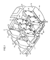
- FIG. 1 is a general perspective view showing a vehicle storage box structure according to a first embodiment of the present invention.
- a first seat row 2 in a vehicle interior compartment of a vehicle, a first seat row 2, a second seat row 3 and a third seat row 4 are arranged parallel to each other in a frontward-rearward (i.e., longitudinal) direction of the vehicle in this order.
- the first seat row 2 is made up of a driver seat 5 and a front passenger seat 6, and disposed on a frontmost side of a floor panel 1 defining a bottom surface of the vehicle interior compartment.
- Each of the second and third seat rows 3, 4 is made up of two or more rear passenger seats arranged in side-by-side relation in a widthwise (i.e., lateral) direction of the vehicle (more specifically, the second and third seat rows 3, 4 are made up, respectively, of three unit seats 7 to 9, and two unit seats 10, 11, as will be described later).
- the vehicle in this embodiment is a type with a right-hand steering wheel, and therefore a right seat and a left seat in the first seat row 2 serve as the driver seat 5 and the front passenger seat 6, respectively.
- Each of the driver seat 5 and the front passenger seat 6 of the first seat row 2 comprises a seat cushion 13 defining a seating surface, and a seat back 14 pivotally supported relative to a rear end of the seat cushion 13 and adapted to stand upwardly.
- the driver seat 5 and the front passenger seat 6 are arranged in side-by-side, spaced-apart relation to each other in the lateral direction, and a console box 15 having a function, such as an armrest allowing an elbow of a driver or a passenger seated in the front passenger seat 6 to be placed thereon, is provided on a portion of the floor panel 1 located between the driver seat 5 and the front passenger seat 6, to protrude upwardly from the floor panel 1.
- the second seat row 3 is made up of three unit seats 7 to 9 arranged in side-by-side relation in the lateral direction, wherein each of the unit seats 7 to 9 is equipped with a seat cushion 17 and a seat back 18, independently.
- the third seat row 4 is made up of two unit seats 10, 11 arranged in side-by-side relation in the lateral direction, wherein each of the unit seats 10, 11 is equipped with a seat cushion 20 and a seat back 21, independently.
- each of the unit seats 7 to 9 in the second seat row 3 is supported relative to a pair of right and left support plates 28 set on the floor panel 1, through two pairs of front and rear links 26, 27 each extending upwardly.
- Each of the front links 26 has an upper end pivotally supported relative to a lateral surface of a front portion of the seat cushion 17 through a pivot shaft 29, and a lower end pivotally supported relative to a front portion of the support plate 28.
- Each of the rear link 27 has an upper end fixed to a lateral surface of a lower end of the seat back 18 through a fastening member (not shown), and a lower end pivotally supported relative to a rear portion of the support plate 28 through a pivot shaft 31.
- the reference numeral 25 indicates a protective cover which covers right and left sides of the seat cushion 13 and others to conceal the upper ends (i.e., connection portions to the seat cushion 17 and the seat back 18) of the front and rear links 26, 27, and others.
- FIG. 3 shows one of the unit seats 7 to 9 in a state after detaching the protective cover 25.
- a link 34 is fixed to a lateral surface of a rear portion of the seat cushion 17 through a fastening member 32.
- the coupling link 34 extends from a fixed portion relative to the seat cushion 17 curvedly upwardly and rearwardly, and a distal end of the coupling link 34 is pivotally supported relative to the upper end of the rear link 27 through a pivot shaft 33.
- the support plate 28 is provided with a lock device 35 adapted to hold the lower end of the rear link 27 so as to restrain the rear link 27 from being rotated about the pivot shaft 31.
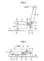
- a rotational displacement of the rear link 27 is restrained by the lock device 35 to allow the seat back 18 to be held in a standing position where it stands upwardly relative to the seat cushion 17, while allowing the seat cushion 17 to be held in a position where it is spaced apart from the support plate 28 upwardly by a given distance, as shown in FIGS. 2 and 3 .
- An operation lever (not shown) associated with an internal gear mechanism of the lock device 35 is provided at a given position of the seat cushion 17 or the seat back 18, in such a manner that a locked state of the rear link 27 by the lock device 35 is released in response to a passenger's manual operation of the operation lever.
- the rear link 27 In a state after the locked state of the rear link 27 is released, when a passenger applies a force to the seat back 18 in a direction for pushing down the seat back frontwardly, the rear link 27 is rotationally displaced frontwardly together with the seat back 18, as shown in FIG. 4 .
- the coupling link 34 is swingingly displaced frontwardly and downwardly, and the front link 26 is rotationally displaced frontwardly. According to these displacements, the seat cushion 17 is moved frontwardly and downwardly, and the seat back 18 is displaced to a folded position where it is folded down on the seat cushion 17, as shown in FIG. 4 .
- Each of the above unit seats 7 to 9 has a box support portion 36 provided in a back surface of the seat back 18 thereof, and adapted to support an after-mentioned storage box 40 (see, particularly, FIGS. 5 to 7 ) for allowing an article, such as a small article, to be stored therein.
- the box support portion 36 includes four recesses 38 formed, respectively, in four corner regions of the back surface of the seat back 18, and four engagement shafts 39 provided inside the respective recesses 38 to extend in the lateral direction.
- the engagement shaft 39 in each of the recesses 38 is adapted to lock a corresponding one of four hooks 45 (see FIG. 9 ) of the after-mentioned storage box 40 so as to allow the storage box 40 to be demountably mounted to the seat back 18.
- the third seat row 4 fundamentally has the same structure as that of the second seat row 3. Specifically, each of the unit seats 10, 11 in the third seat row 4 is supported displaceably between a standing position where the seat back 21 stands upwardly and a folded position where the seat back 21 is folded down on the seat cushion 20, wherein the seat cushion 20 is adapted to be moved frontwardly and downwardly in the folded position. Further, in the same manner as that in each of the unit seats 7 to 9 in the second seat row 3, the box support portion 36 is provided in a back surface of the seat back 21, to allow the after-mentioned storage box 40 to be releasably locked thereby.
- a rear luggage area L having a luggage floor 1a defining a bottom surface thereof is formed in a rear end of the vehicle interior compartment, and the third seat row 4 is disposed in front of and adjacent to the rear luggage area L.
- the seat cushion 20 is moved downwardly by a given distance, so that an approximately continuous flat floor surface is formed by the back surfaces of the seat backs 21 folded down on the respective seat cushions 20 (i.e., an upper surfaces of the seat backs 21 in the folded position) and the luggage floor 1a, and a wide luggage space having the above floor surface defining a bottom surface thereof is formed in a rear of the vehicle interior compartment.
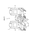
- FIGS. 5 to 7 are perspective views showing a use mode of a storage box 40.
- FIGS. 5 to 7 show one example of the use mode where the storage box 40 is mounted to the seat back 18 of a laterally central one 8 of the unit seats 7 to 9 making up the second seat row 3.
- FIGS. 6 and 7 illustrate the console box 15 arranged between the driver seat 5 and the front passenger seat 6, in combination with the storage box 40.
- the storage box 40 is used in the state after the seat back 18 is folded down on the seat cushion 17. As mentioned above, when the seat back 18 is folded down, the seat cushion 17 is displaced downwardly (i.e., lowered in height) in conjunction with the fold-down of the seat back 18. Thus, a height position of the storage box 40 supported relative to the back surface of the folded seat back 18 can be relatively lowered, as shown in FIG. 6 .
- FIG. 9 is an explanatory diagram showing an operation of mounting the storage box 40 to the back surface of the seat back of the unit seat.
- the storage box 40 has a box body 42 and a lid member 43 (as will be described in detail later), wherein the box body 42 is provided with a plurality of (in this embodiment, four) hooks 45 protruding from a lower surface thereof.
- the hooks 45 are pivotally supported relative to the lower surface of the box body 42 at positions (in this embodiment, four positions corresponding to the respective four box support portions 36 provided to the seat back 18), through pivot shafts 46.
- Each of the hooks 45 is biased by biasing means (not shown) in a specific rotation direction about the pivot shaft 46 (i.e., in a direction causing the hook 45 to be brought into engagement with a corresponding one of the engagement shafts 39 of the box support portion 36), in such a manner as to be held in a posture illustrated in FIG. 9 , in a normal state.
- the storage box 40 has an operation lever (not shown) provided at a given position thereof and associated with the hooks 45.
- the operation lever can be manually moved to rotate the hooks 45 in a given direction (the arrowed direction in FIG. 10A ) so as to release the engagement between respective ones of the hooks 45 and the engagement shafts 39 to allow the storage box 40 to be pulled upwardly.
- the storage box 40 includes a box body 42 internally having a storage space 41 to store an article, such as a small article, therein, and a lid member 43 pivotally supported relative to a rear end of the box body 42 through a hinge mechanism (not shown) or the like.
- the storage space 41 is defined in the box body 42 in such a manner as to be opened upwardly when the box body 42 is supported relative to the back surface of the seat back 18 in the state after being folded down on the seat cushion 17, as shown in FIGS. 6 and 7 . In this state, a top opening of the box body 42 is openably closed by the lid member 43.
- a fastening device such as a magnet fastener (not shown), is provided between respective mating surfaces of the box body 42 and the lid member 43, to allow the lid member 43 to be held in a closed position (the position in FIG. 6 ) in a normal state.
- the lid member 43 When a passenger manually pulls the lid member 43 held in the closed position, upwardly while putting his/her fingers in a grip recess 43a formed in a front end of the lid member 43, the lid member 43 is rotationally displaced about the rear end thereof upwardly, and thereby the storage space 41 of the box body 42 is opened upwardly, as shown in FIG. 7 . After the lid member 43 is manually opened to expose the top opening of the box body 42, an operation of taking an article in and out of the storage space 41 will be performed through the top opening.
- FIGS. 5 to 7 show one example where the storage box 40 is mounted to the seat back 18 of the laterally central one 8 of the three unit seats 7 to 9 making up the second seat row 3, the storage box 40 may be used in a mode where it is mounted to another rear passenger seat, i.e., one of the unit seats 7, 9 on the right and left sides of the laterally central unit seat 8, or one of the unit seats 10, 11 in the third seat row 4.
- the storage box structure according the first embodiment comprises the storage box 40 adapted to store an article therein and to be supported relative to the back surface of each of the seat backs 18, 21 of the unit seats 7 to 9, 10, 11, wherein each of the seat backs 18, 21 is supported displaceably between the standing position where it stands upwardly, and the folded position where it is folded down on a corresponding one of the seat cushions 17, 20, and the storage box 40 includes the box body 42 having the storage space 41 defined to be opened upwardly when the box body 42 is supported relative to the back surface of the seat back 18 (or 21) set in the folded position, and the lid member 43 adapted to openably close a top opening of the box body 42, and wherein the storage box 40 is adapted to be releasably locked relative to the box support portion 36 provided in each of the back surfaces of the seat backs 18, 21.
- the storage box structure according the first embodiment has an advantage of being
- the box support portion 36 adapted to support the storage box 40 for storing an article therein is provided to each of the seat backs 18, 21 of the unit seats 7 to 9, 10, 11 each serving as a rear passenger seat.
- the storage box structure according to the first embodiment has an advantage of being able to store an article using the storage box 40 according to need while maximizing a maximum seating capacity, without the need for sacrificing an installation space of the unit seats 7 to 9, 10, 11 (i.e., without the need for reducing the number of passenger seats) to ensure a mounting position of the storage box 40.
- the storage space 41 of the storage box 40 is defined to be opened upwardly when the seat back 18 (or 21) supporting the storage box 40 is displaced to the folded position.
- the seat back 18 (or 21) is folded down to use the storage box 40 supported relative to the back surface of the seat back 18 (or 21)
- a passenger can readily access to the storage space 41 of the storage box 40 from the top opening of the storage space 41 so as to take an article in and out of the storage box 40.
- the lid member 43 adapted to openably close the storage space 41 is located on an upper side relative to the box body 42. This provides an advantage of being able to manually open and close the lid member 43 in an easy manner.
- the storage box 40 is adapted to be releasably locked relative to the box support portion 36 provided to each of the seat backs 18, 21 of the unit seats 7 to 9, 10, 11. This provides an advantage of being able to more adequately ensure passenger comfort in the vehicle interior compartment in a non-use mode of the storage box 40, for example, by demounting the storage box 40 from the seat back 18 (or 21) and moving the storage box 41 to a position causing no obstruction.
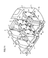
- the storage box 40 is mounted to one of the seat backs 18 in the second and third seat rows 3, 4, as shown in FIG. 8 , the presence of the storage box 40 protruding rearwardly from the back surface of the seat back 18 is likely to cause oppressive feeling of the passenger seated in the third seat row 4.
- the storage box 40 in the first embodiment is demountable relative to the seat back 18.
- the storage box 40 can be demounted from the seat back 18, and then stored in the rear luggage area L, or re-mounted to one of the seat backs 21 in the third seat row 4, as shown in FIG. 11 .
- This provides an advantage of being able to effectively prevent seating environment of a passenger from deteriorating due to the presence of the storage box 40 even in the situation where most of the unit seats are occupied by passengers, so as to more adequately ensure passenger comfort in the vehicle interior compartment in the non-use mode.
- the box support portion 36 is provided to each of the seat backs 18, 21 of the unit seats 7 to 9, 10, 11 making up the second and third seat rows 3, 4.
- the mounting position of the storage box 40 can be flexibly changed depending on which of the unit seats 7 to 9, 10, 11 a passenger who intends to use the storage box 40 occupies. This provides an advantage of being able to more effectively improve usability of the storage box.
- the storage box 40 can be situated in a position allowing the passengers seated in the unit seats 7, 9 to readily access to the storage box 40, by folding the seat back 18 of the central unit seat 8, and supporting the storage box 40 by the box support portion 36 in the back surface of the folded seat back 18, as shown in FIGS. 5 and 6 .
- This makes it possible to effectively improve usability of the storage box 40 for the two passengers.
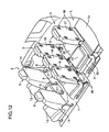
- the storage box 40 can be situated in a position allowing the passenger seated in the unit seat 10 to readily access to the storage box 40, by folding the seat back 21 of the other unit seat 11, and supporting the storage box 40 by the box support portion 36 in the back surface of the folded seat back 21, as shown in FIG. 12 .
- the box support portion 36 is provided to each of the seat backs 21 in the third seat row 4 arranged in adjacent relation to the rear luggage area L of the vehicle interior compartment.
- the storage box 40 can be supported by the box support portion 36 of one of the seat backs 21, and mounted in such a manner as to protrude toward the rear luggage area L, as shown in FIG. 11 .
- This provides an advantage of being able to adequately ensure a mounting position of the storage box 40 in the non-use mode without narrowing a utility space for a passenger seated in the third seat row 4.
- the storage box 40 is mounted to one of the seat backs 21 in the third seat row 4 in the above manner, the storage box 40 is likely to hinder the storage of the relatively large article.
- the box support portion 36 is also provided to each of the seat backs 18 in the second seat row 3 located in a longitudinally intermediate position of the vehicle interior compartment.
- the storage box 40 can be mounted to one of the seat backs 18 in the second seat row 3, as shown in FIGS. 5 and 8 , to effectively avoid the undesirable situation where the rear luggage area L is narrowed by the storage box 40.
- This provides an advantage of being able to appropriately ensure the mounting position of the storage box 40 while adequately maintaining a storage capacity of the rear luggage area L.
- the storage box 40 can be mounted to one of the seat backs 18 in the second seat row 3, to effectively avoid an undesirable situation where the storage box 40 mounted to one of the seat backs 21 in the third seat row 4, for example, to form a floor surface approximately continuous with the luggage floor 1a, hinders the storage of the larger luggage. This provides an advantage of being able to allow even a fairly large luggage to be stored in the rear of the vehicle without difficulty.
- each of the rear passenger seats each having the seat back provided with the box support portion 36 i.e., each of the unit seats 7 to 9, 10, 11 in the second and third seat rows 3, 4, includes the link mechanism comprising the links 26, 27, as shown in FIGS. 2 to 4 (i.e., a displacement mechanism adapted to displace the seat cushion 17 (or 20) downwardly by a given distance in conjunction with the displacement of the seat back 18 (or 21) toward the folded position).
- a height position of the back surface (i.e., mounting surface) of the seat back 18 (or 21) in the folded position can be relatively lowered.
- This provides an advantage of being able to effectively avoid an undesirable situation where a height position of the storage box 40 supported relative to the back surface of the folded seat back 18 (or 21) is excessively raised in a use mode of the storage box 40 to cause deterioration in usability of the storage box 40.
- a height position of the storage box 40 is likely to be excessively raised relative to a passenger seated in the surrounding unit seat to preclude the passenger from smoothly operate (e.g., open and close) the lid member 43 of the storage box 40.
- the storage box structure according to the first embodiment wherein each of each of the unit seats 7 to 9, 10, 11 is provided with the displacement mechanism adapted to displace the seat cushion 17 (or 20) downwardly by a given distance has an advantage of being able to lower the height position of the back surface of the seat back 18 (or 21) in the use mode of the storage box 40 so as to avoid the above undesirable situation to effectively improve the usability of the storage box 40.
- the box support portion 36 is provided to each of the seat backs 18, 21 of the unit seats 7 to 9, 10, 11 making up the second and third rows 3, 4.
- the box support portion 36 is provided to only a part of the seat backs 18, 21.
- the box support portion 36 is preferably provided to the seat back 18 of at least a central one 8 of the three unit seats 7 to 9 making up the second seat row 3.
- the above storage box structure has an advantage of being able to effectively enhance utility value of the storage box 40.
- the box support portion 36 may be additionally provided to a seat other than the unit seats 7 to 9, 10, 11 making up the second and third seat rows 3, 4.
- the box support portion 36 may be provided to a back surface of the seat back 14 of the front passenger seat 6.
- the first embodiment shows one example where the box support portion 36 adapted to releasably lock the storage box 40 is provided to each of the seat backs 18, 21 of the unit seats 7 to 9, 10, 11 each serving as a rear passenger seat.
- a box holding portion having the same structure as that of the box support portion 36 may also be provided to a lateral wall of the vehicle interior compartment.
- FIG. 14 shows one example of such a storage box structure. As shown in FIG. 14 , a lateral wall of the rear of the vehicle interior compartment is provided with a box holding portion 50 having the same structure as that of the box support portion 36, and the storage box 40 can be releasably locked relatively to the box holding portion 50.
- the mounting position of the storage box 40 in the non-use mode can be easily ensured by utilizing a portion other than seat backs 18, 21.
- This provides an advantage of being able to variously utilize a space in the vehicle interior compartment while appropriately changing the mounting position of the storage box 40 between the box holding portion 50 provided to the lateral wall of the vehicle interior compartment and each of the box support portions 36 provided to the seat backs 18, 21 depending on a configuration of a luggage to be stored in the rear luggage area L, a seating position of a passenger, or the like.
- FIGS. 15 and 16 show a vehicle storage box structure according to a second embodiment of the present invention.
- a storage box 60 in the second embodiment comprises a box body 62, a pair of right and left armrest members 64 provided on a top surface of the box body 62, and a table member 63 provided between the right and left armrest members 64.
- a seat back 18 of a central one 8 of three unit seats 7 to 9 arranged in side-by-side relation in a widthwise (i.e., lateral) direction of a vehicle to make up a second seat row 3 is folded down on a seat cushion 17 of the laterally central unit seat 8, and the storage box 60 is mounted to a back surface of the folded seat back 18.
- the box support portion 36 illustrated in FIGS. 2 , 9 and 10 is provided to the back surface of at least the unit seat 8, and a hook (not shown) equivalent to the hook 45 illustrated in FIGS. 9 and 10 is provided to a lower surface of the box body 62.
- the hook is adapted to be locked relatively to the box support portion 36 to allow the storage box 60 to be releasably supported relative to the seat back 18.
- the table member 63 is formed to have an approximately flat top surface 63a adapted to allow an article to be placed thereon, and supported movably in a frontward-rearward (i.e., longitudinal) direction of the vehicle, relative to the box body 62 of the storage box 60. Further, the table member 63 is adapted to be slidably moved in the longitudinal direction between a normal position illustrated in FIG. 15 and a frontmost position where it largely protrudes frontwardly relative to the box body 62, as shown in FIG. 16 , according to a manual operation of a passenger.
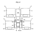
- FIG. 17 is a schematic top view showing a state after the table member 63 is moved to the frontmost position.
- the table member 63 is adapted, when it is moved to the frontmost position, to allow an approximately continuous table surface (article mounting surface) to be formed between a top surface 63a of the table member 63 and a top surface 15a of the aforementioned console box 15.
- the console box 15 having the top surface 15a forming an approximately continuous table surface in cooperation with the top surface 63a of the table member 63 corresponds to a mount member set forth in the appended claims.
- the pair of right and left armrest members 64 are provided at positions allowing two passengers seated in the respective unit seats adjacent to the unit seat 8 having the storage box 40 mounted thereto (i.e., the respective unit seats 7, 9 located on right and left sides of the laterally central unit seat 8) to place their elbows thereon, and supported relatively to the box body 62 movably in the longitudinal direction, in the same manner as that in the table member 63.
- Each of the armrest members 64 is adapted to be slidably moved in the longitudinal direction between a normal position illustrated in FIG. 15 and a rearmost position where it protrudes rearwardly relative to the box body 62 by a given distance, as shown in FIG. 16 , according to a manual operation of a passenger.
- each of the armrest members 64 when each of the armrest members 64 is moved from the normal position illustrated in FIG. 15 to the rearmost position illustrated in FIG. 16 , a rear end of the armrest member 64 is located in a vicinity of a flank of a passenger seated in the unit seat 7 (or 9). That is, each of the armrest members 64 is adapted to be moved to the rearmost position illustrated in FIG. 16 , in such a manner that the rear end of the armrest member 64 is located at a position allowing an elbow of the passenger to be adequately placed thereon.
- the box body 62 of the storage box 60 has a pair of right and left cup holders 65 provided in a front end thereof.
- Each of the cup holders 65 is formed as a concave portion capable of receiving therein a bottom portion of a beverage container, such as a beverage can or plastic bottle, and adapted to be covered (i.e., concealed) by a front end of a corresponding one of the armrest members 64 set in the normal position illustrated in FIG. 15 , from thereabove.
- Each of the cup holders 65 is also adapted to be exposed to the outside (i.e., placed in a usable state) in conjunction of the longitudinal movement of the corresponding armrest member 64 from the normal position toward the rearmost position illustrated in FIG. 16 .
- the box body 62 has a storage space 61 adapted to store an article, such as a small article, therein, and defined to be opened upwardly when the said box body 62 is supported relative to the back surface of the seat back 18 set in the folded position.
- the storage box 60 includes a lid member 67 pivotally supported relative to a rear edge of the box body 62 in such a manner as to openably close a top opening of the storage space 61.
- the lid member 67 closing the storage space 61 is adapted to be covered (i.e., concealed) by the table member 63 set in the normal position, and exposed to the outside in conjunction with the longitudinal movement of the table member 63 toward the frontmost position illustrated in FIG. 16 .
- the storage box 60 capable of storing an article therein is adapted to be mounted to the seat back 18 of the unit seat 8 serving as a rear passenger seat, and the storage space 61 of the storage box 60 is defined to be opened upwardly when the box body 62 is supported relative to the back surface of the seat back 18 set in the folded position.
- the storage box structure according to the second embodiment has an advantage of being able to achieve an excellent balance between ensuring of a maximum seating capacity and improvement in usability of the storage box, as with the first embodiment.
- the table member 63 having an approximately flat top surface 63a is provided on the top surface of the box body 62 of the storage box 60.
- a passenger can place an article, such as a small article, on the top surface 63a of the table member 63 to conveniently use the article while maintaining the article in a stable state.
- the table member 63 has an advantage of being able to use the storage box for another purpose other than the purpose of storing an article therein, and thereby more improve utility of the storage box.
- the table member 63 is supported movably in the longitudinal direction of the vehicle, relative to the box body 62 of the storage box 60 in the state after being mounted to the seat back 18 set in the folded position, in such a manner that the top surface 63a of the table member 63 in the state after being moved to a frontmost position in a movable range thereof forms an approximately continuous table surface in cooperation with the top surface 15a of the console box 15 disposed in front of the unit seat 8.
- This provides an advantage of being able to readily form a wide table surface capable of allowing even a relatively large article to be placed thereon, in the vehicle interior compartment.
- the table member 63 is adapted to be moved to the frontmost position in the movable range in such a manner as to form an approximately continuous table surface between the top surface 63a of the table member 63 and the top surface 15a of the console box 15 located in front of the table member 63.
- This provides an advantage of being able to form a longitudinally-continuous wide table surface in the vehicle interior compartment using a simple structure, and reliably support an article, e.g., even a large article which cannot be supported only by the table member 63.
- the table member 63 is adapted to be moved frontwardly relative to the box body 62 of the storage box 60 mounted to the seat back 18 in the second seat row 3, in such a manner as to form an approximately continuous table surface between the top surface 63a of the table member 63, and the top surface 15a of the console box 15 provided between the driver seat 5 and the front passenger seat 6.
- a wide table surface allowing passengers seated in both the first and second seat rows 2, 3 to access thereto can be formed based on a simple and economical structure utilizing the existing console box 15. This provides an advantage of being able to allow more passengers to place an article or the like on the table surface, and more effectively achieve improvement in utility of the storage box 60 based on the table member 63.
- the storage box 60 with the table member 63 is mounted to the seat back 18 of the laterally central unit seat 8 in the second seat row 3 made up of the three unit seats (three rear passenger seats) 7 to 9 arranged in side-by-side relation in the lateral direction of the vehicle, and the table member 63 is adapted to be moved frontwardly relative to the box body 62 of the storage box 60 in such a manner as to form an approximately continuous table surface between the table member 63 and the console box 15.
- the table surface can be formed at a position accessible by each of two passengers seated in the respective unit seats 7, 9 on the right and left sides of the laterally central unit seat 8. This provides an advantage of being able to more effectively enhance the utility value of the table member 63, as compared with a storage box structure where the storage box 60 with the table member 63 is mounted to another unit seat (7 or 9).
- the armrest members 64 are disposed laterally on both sides of the table member 63 provided to the laterally central unit seats 8, at positions allowing two passengers seated in the respective unit seats 7, 9 on the right and left sides of the laterally central unit seat 8 to place their elbows thereon.
- This provides an advantage of being able to allow the passengers seated in the respective unit seats 7, 9 to have a more comfortable posture so as to effectively improve passenger comfort during seating.
- the armrest members 64 provided to the storage box 60 in this manner provides an advantage of being able to expand the functions of the storage box 60 so as to enhance the utility value of the storage box 60 to allow a limited space in the vehicle interior compartment to be more effectively utilized.
- each of the armrest members 64 is supported movably in the longitudinal direction of the vehicle, relative to the seat back 18. This provides an advantage of being able to adjust a longitudinal position of the armrest member 64 in conformity to a position of the passenger's elbow (in the second embodiment, move the armrest member 64 to the rearmost position illustrated in FIG. 16 ) so as to more adequately support the passenger's elbow by the armrest member 64.
- the cup holders 65 disposed laterally on both sides of the table member 63 are adapted to be selectively concealed and exposed in conjunction with the longitudinal movement of the armrest members 64.
- each of the armrests members 64 can be set at a position (the normal position illustrated in FIG. 15 ) where it conceals a corresponding one of the cup holders 65, to effectively reduce an overall size of the storage box 60.
- the armrests members 64 can be moved to the rearmost position illustrated in FIG. 16 to expose the cup holders 65 so as to adequately hold a beverage container or the like using the cup holders 65.
- the seat back 18 of the laterally central one 8 of the unit seats 7 to 9 making up the second seat row 3 is folded down on the seat cushion 17 of the laterally central unit seat 8
- the storage box 60 with the table member 63 is mounted to the back surface of the folded seat back 18, whereafter the table member 63 is moved frontwardly relative to the box body 62 of the storage box 60 to form an approximately continuous table surface between the top surface 63a of the table member 63 and the top surface 15a of the console box 15
- a member (mount member set forth in the appended claims) located in front of the table member 63 to form the approximately continuous table surface in cooperation with the table member 63 is not limited to the console box 15.
- a back surface of the seat back 14 (i.e., a top surface of the folded seat back 14) of the front passenger seat 6 may be used for forming the approximately continuous table surface.
- the table member 63 may be moved frontwardly relative to the box body 62 of the storage box 60 to form an approximately continuous table surface between the top surface 63a of the table member 63 and the back surface of the folded seat back 14 of the front passenger seat 6.
- the table member 63 may be moved frontwardly relative to the box body 62 of the storage box 60 to form an approximately continuous table surface between the top surface 63a of the table member 63 and the back surface of the folded seat back 18 in the second seat row 3.
Landscapes
- Engineering & Computer Science (AREA)
- Mechanical Engineering (AREA)
- Transportation (AREA)
- Aviation & Aerospace Engineering (AREA)
- Physics & Mathematics (AREA)
- Thermal Sciences (AREA)
- Vehicle Step Arrangements And Article Storage (AREA)
- Seats For Vehicles (AREA)
Applications Claiming Priority (2)
| Application Number | Priority Date | Filing Date | Title |
|---|---|---|---|
| JP2007222344A JP2009051456A (ja) | 2007-08-29 | 2007-08-29 | 車両用シートテーブル構造 |
| JP2007222343A JP2009051455A (ja) | 2007-08-29 | 2007-08-29 | 車両用収納ボックス構造 |
Publications (2)
| Publication Number | Publication Date |
|---|---|
| EP2030842A2 true EP2030842A2 (fr) | 2009-03-04 |
| EP2030842A3 EP2030842A3 (fr) | 2012-10-17 |
Family
ID=40219279
Family Applications (1)
| Application Number | Title | Priority Date | Filing Date |
|---|---|---|---|
| EP08105100A Withdrawn EP2030842A3 (fr) | 2007-08-29 | 2008-08-22 | Structure de boîte de rangement pour véhicule |
Country Status (1)
| Country | Link |
|---|---|
| EP (1) | EP2030842A3 (fr) |
Cited By (7)
| Publication number | Priority date | Publication date | Assignee | Title |
|---|---|---|---|---|
| FR2952889A1 (fr) * | 2009-11-26 | 2011-05-27 | Alstom Transport Sa | Voiture ferroviaire |
| FR2981895A1 (fr) * | 2011-10-27 | 2013-05-03 | Renault Sa | Coffre de rangement pour vehicule automobile et siege automobile comprenant un coffre |
| US9096180B1 (en) | 2013-11-08 | 2015-08-04 | Dan Malin | Container |
| CN113415243A (zh) * | 2021-08-02 | 2021-09-21 | 重庆工业职业技术学院 | 便于搁置手持式多媒体设备的交通工具座椅 |
| CN114312517A (zh) * | 2022-02-10 | 2022-04-12 | 浙江极氪智能科技有限公司 | 一种乘用车后排座椅及汽车 |
| CN114392066A (zh) * | 2021-03-31 | 2022-04-26 | 江苏福维健康科技有限公司 | 一种便于拆卸运输的代步车及拆卸运输方法 |
| US11535176B2 (en) * | 2019-07-22 | 2022-12-27 | Faurecia Interieur Industrie | Modular trim element |
Citations (1)
| Publication number | Priority date | Publication date | Assignee | Title |
|---|---|---|---|---|
| JP2006021608A (ja) | 2004-07-07 | 2006-01-26 | Honda Motor Co Ltd | 脱着式収納ボックス |
Family Cites Families (5)
| Publication number | Priority date | Publication date | Assignee | Title |
|---|---|---|---|---|
| DE19854240A1 (de) * | 1998-11-24 | 2000-05-31 | Peter Butz Gmbh Verwaltungs Kg | Ladungssicherungsvorrichtung für Personenkraftwagen, wie für Kombinationskraftwagen, Großraumlimousinen o. dgl. |
| US6702375B1 (en) * | 2000-02-29 | 2004-03-09 | Johnson Controls Technology Company | Activity center for a vehicle |
| DE10357356A1 (de) * | 2003-12-09 | 2005-07-07 | Sitech Sitztechnik Gmbh | Vorrichtung zum Aufnehmen von Gegenständen für den Einbau in ein Fahrzeug |
| JP4123521B2 (ja) * | 2004-03-31 | 2008-07-23 | テイ・エス テック株式会社 | 車両用コンソール |
| GB2424575B (en) * | 2005-04-01 | 2009-02-25 | Johnson Controls Automotive Uk | An anchor support for interchangeable modules |
-
2008
- 2008-08-22 EP EP08105100A patent/EP2030842A3/fr not_active Withdrawn
Patent Citations (1)
| Publication number | Priority date | Publication date | Assignee | Title |
|---|---|---|---|---|
| JP2006021608A (ja) | 2004-07-07 | 2006-01-26 | Honda Motor Co Ltd | 脱着式収納ボックス |
Cited By (10)
| Publication number | Priority date | Publication date | Assignee | Title |
|---|---|---|---|---|
| FR2952889A1 (fr) * | 2009-11-26 | 2011-05-27 | Alstom Transport Sa | Voiture ferroviaire |
| FR2981895A1 (fr) * | 2011-10-27 | 2013-05-03 | Renault Sa | Coffre de rangement pour vehicule automobile et siege automobile comprenant un coffre |
| US9096180B1 (en) | 2013-11-08 | 2015-08-04 | Dan Malin | Container |
| US11535176B2 (en) * | 2019-07-22 | 2022-12-27 | Faurecia Interieur Industrie | Modular trim element |
| CN114392066A (zh) * | 2021-03-31 | 2022-04-26 | 江苏福维健康科技有限公司 | 一种便于拆卸运输的代步车及拆卸运输方法 |
| CN114392066B (zh) * | 2021-03-31 | 2024-03-29 | 江苏福维健康科技有限公司 | 一种便于拆卸运输的代步车及拆卸运输方法 |
| CN113415243A (zh) * | 2021-08-02 | 2021-09-21 | 重庆工业职业技术学院 | 便于搁置手持式多媒体设备的交通工具座椅 |
| CN113415243B (zh) * | 2021-08-02 | 2022-07-01 | 重庆工业职业技术学院 | 便于搁置手持式多媒体设备的交通工具座椅 |
| CN114312517A (zh) * | 2022-02-10 | 2022-04-12 | 浙江极氪智能科技有限公司 | 一种乘用车后排座椅及汽车 |
| CN114312517B (zh) * | 2022-02-10 | 2023-04-25 | 浙江极氪智能科技有限公司 | 一种乘用车后排座椅及汽车 |
Also Published As
| Publication number | Publication date |
|---|---|
| EP2030842A3 (fr) | 2012-10-17 |
Similar Documents
| Publication | Publication Date | Title |
|---|---|---|
| EP1449710B1 (fr) | Dispositif de siège comprenant un siège auxiliaire escamotable | |
| US6488327B1 (en) | Seating and cargo storage system for a vehicle | |
| EP2030842A2 (fr) | Structure de boîte de rangement pour véhicule | |
| US4792174A (en) | Snack tray for automobile | |
| US7431365B2 (en) | Console assembly for a vehicle | |
| US7237816B1 (en) | Automotive center console with open front face | |
| JP2009051455A (ja) | 車両用収納ボックス構造 | |
| US20070205642A1 (en) | Automotive center console with combination rear wall and articulated armrest | |
| US10829020B2 (en) | Vehicle seating arrangement | |
| JP2003080982A (ja) | 車両シート装置 | |
| JP4955352B2 (ja) | 乗り物用テーブル | |
| JP6316103B2 (ja) | 車両用スロープ及びそれを備えた車両 | |
| US6027164A (en) | Combination seat and armrest with storage compartments | |
| JP4632041B2 (ja) | 車両のスライド式コンソールボックス構造 | |
| GB2412849A (en) | Vehicle seat assembly | |
| EP0980789A1 (fr) | Siège de véhicule avec système de rangement sous l'assise | |
| JP4180398B2 (ja) | 車両用シート収納構造 | |
| WO2001005620A1 (fr) | Siege arriere de vehicule motorise avec contenant et couvercle a deux faces | |
| JP2001001805A (ja) | 車両用センタシートの取付構造 | |
| GB2413270A (en) | Vehicle seat assembly | |
| JP2806835B2 (ja) | 補助シート | |
| JP2002067808A (ja) | 車両用荷室構造 | |
| JP2009051456A (ja) | 車両用シートテーブル構造 | |
| JP2001122030A (ja) | 車両用多目的コンソール | |
| JP2004141409A (ja) | アームレスト構造 |
Legal Events
| Date | Code | Title | Description |
|---|---|---|---|
| PUAI | Public reference made under article 153(3) epc to a published international application that has entered the european phase |
Free format text: ORIGINAL CODE: 0009012 |
|
| AK | Designated contracting states |
Kind code of ref document: A2 Designated state(s): AT BE BG CH CY CZ DE DK EE ES FI FR GB GR HR HU IE IS IT LI LT LU LV MC MT NL NO PL PT RO SE SI SK TR |
|
| AX | Request for extension of the european patent |
Extension state: AL BA MK RS |
|
| PUAL | Search report despatched |
Free format text: ORIGINAL CODE: 0009013 |
|
| AK | Designated contracting states |
Kind code of ref document: A3 Designated state(s): AT BE BG CH CY CZ DE DK EE ES FI FR GB GR HR HU IE IS IT LI LT LU LV MC MT NL NO PL PT RO SE SI SK TR |
|
| AX | Request for extension of the european patent |
Extension state: AL BA MK RS |
|
| RIC1 | Information provided on ipc code assigned before grant |
Ipc: B60N 2/20 20060101ALI20120912BHEP Ipc: B60R 7/04 20060101AFI20120912BHEP |
|
| AKY | No designation fees paid | ||
| REG | Reference to a national code |
Ref country code: DE Ref legal event code: R108 |
|
| REG | Reference to a national code |
Ref country code: DE Ref legal event code: R108 Effective date: 20130626 |
|
| STAA | Information on the status of an ep patent application or granted ep patent |
Free format text: STATUS: THE APPLICATION IS DEEMED TO BE WITHDRAWN |
|
| 18D | Application deemed to be withdrawn |
Effective date: 20130418 |