EP2029894B1 - Reciprocating compressor or pump - Google Patents
Reciprocating compressor or pump Download PDFInfo
- Publication number
- EP2029894B1 EP2029894B1 EP07719906.5A EP07719906A EP2029894B1 EP 2029894 B1 EP2029894 B1 EP 2029894B1 EP 07719906 A EP07719906 A EP 07719906A EP 2029894 B1 EP2029894 B1 EP 2029894B1
- Authority
- EP
- European Patent Office
- Prior art keywords
- compressor
- cylinder liner
- piston
- cylinder
- manifold
- Prior art date
- Legal status (The legal status is an assumption and is not a legal conclusion. Google has not performed a legal analysis and makes no representation as to the accuracy of the status listed.)
- Not-in-force
Links
- 239000004944 Liquid Silicone Rubber Substances 0.000 claims description 25
- 229920002379 silicone rubber Polymers 0.000 claims description 25
- 230000033001 locomotion Effects 0.000 claims description 16
- 239000012530 fluid Substances 0.000 claims description 6
- 230000000694 effects Effects 0.000 claims description 3
- 239000007789 gas Substances 0.000 description 56
- 230000006835 compression Effects 0.000 description 24
- 238000007906 compression Methods 0.000 description 24
- 229910052751 metal Inorganic materials 0.000 description 21
- 239000002184 metal Substances 0.000 description 21
- 230000013011 mating Effects 0.000 description 19
- 239000000463 material Substances 0.000 description 14
- 235000014676 Phragmites communis Nutrition 0.000 description 12
- 238000007789 sealing Methods 0.000 description 7
- 230000004888 barrier function Effects 0.000 description 6
- 238000005452 bending Methods 0.000 description 5
- 238000006073 displacement reaction Methods 0.000 description 5
- 230000008901 benefit Effects 0.000 description 4
- 230000007246 mechanism Effects 0.000 description 4
- 230000002829 reductive effect Effects 0.000 description 4
- 230000008878 coupling Effects 0.000 description 3
- 238000010168 coupling process Methods 0.000 description 3
- 238000005859 coupling reaction Methods 0.000 description 3
- 230000007423 decrease Effects 0.000 description 3
- 239000011796 hollow space material Substances 0.000 description 3
- 238000000465 moulding Methods 0.000 description 3
- 230000004044 response Effects 0.000 description 3
- 244000273256 Phragmites communis Species 0.000 description 2
- 230000005540 biological transmission Effects 0.000 description 2
- 238000004891 communication Methods 0.000 description 2
- 238000001816 cooling Methods 0.000 description 2
- 238000013461 design Methods 0.000 description 2
- 239000011152 fibreglass Substances 0.000 description 2
- 238000002955 isolation Methods 0.000 description 2
- 238000012423 maintenance Methods 0.000 description 2
- 150000002739 metals Chemical class 0.000 description 2
- 238000000034 method Methods 0.000 description 2
- 235000012771 pancakes Nutrition 0.000 description 2
- 230000036961 partial effect Effects 0.000 description 2
- 230000002093 peripheral effect Effects 0.000 description 2
- 239000004033 plastic Substances 0.000 description 2
- 229920003023 plastic Polymers 0.000 description 2
- 239000012858 resilient material Substances 0.000 description 2
- 238000012546 transfer Methods 0.000 description 2
- 239000002918 waste heat Substances 0.000 description 2
- XLYOFNOQVPJJNP-UHFFFAOYSA-N water Substances O XLYOFNOQVPJJNP-UHFFFAOYSA-N 0.000 description 2
- HBBGRARXTFLTSG-UHFFFAOYSA-N Lithium ion Chemical compound [Li+] HBBGRARXTFLTSG-UHFFFAOYSA-N 0.000 description 1
- 208000034819 Mobility Limitation Diseases 0.000 description 1
- NINIDFKCEFEMDL-UHFFFAOYSA-N Sulfur Chemical compound [S] NINIDFKCEFEMDL-UHFFFAOYSA-N 0.000 description 1
- 239000004809 Teflon Substances 0.000 description 1
- 229920006362 Teflon® Polymers 0.000 description 1
- 230000009471 action Effects 0.000 description 1
- 229910052782 aluminium Inorganic materials 0.000 description 1
- XAGFODPZIPBFFR-UHFFFAOYSA-N aluminium Chemical compound [Al] XAGFODPZIPBFFR-UHFFFAOYSA-N 0.000 description 1
- 238000013459 approach Methods 0.000 description 1
- 230000000712 assembly Effects 0.000 description 1
- 238000000429 assembly Methods 0.000 description 1
- 230000000903 blocking effect Effects 0.000 description 1
- 238000010276 construction Methods 0.000 description 1
- 238000007598 dipping method Methods 0.000 description 1
- 238000001035 drying Methods 0.000 description 1
- 230000001747 exhibiting effect Effects 0.000 description 1
- 239000002783 friction material Substances 0.000 description 1
- 239000000446 fuel Substances 0.000 description 1
- 230000002401 inhibitory effect Effects 0.000 description 1
- 229910001416 lithium ion Inorganic materials 0.000 description 1
- 238000004519 manufacturing process Methods 0.000 description 1
- 238000012544 monitoring process Methods 0.000 description 1
- 239000011236 particulate material Substances 0.000 description 1
- 230000002028 premature Effects 0.000 description 1
- 230000003449 preventive effect Effects 0.000 description 1
- 230000008569 process Effects 0.000 description 1
- 230000008439 repair process Effects 0.000 description 1
- 230000003252 repetitive effect Effects 0.000 description 1
- 230000000717 retained effect Effects 0.000 description 1
- 238000005070 sampling Methods 0.000 description 1
- 239000004576 sand Substances 0.000 description 1
- 239000011343 solid material Substances 0.000 description 1
- 229910052717 sulfur Inorganic materials 0.000 description 1
- 239000011593 sulfur Substances 0.000 description 1
- 230000000007 visual effect Effects 0.000 description 1
- 239000002699 waste material Substances 0.000 description 1
- 230000003245 working effect Effects 0.000 description 1
Images


Classifications
-
- F—MECHANICAL ENGINEERING; LIGHTING; HEATING; WEAPONS; BLASTING
- F04—POSITIVE - DISPLACEMENT MACHINES FOR LIQUIDS; PUMPS FOR LIQUIDS OR ELASTIC FLUIDS
- F04B—POSITIVE-DISPLACEMENT MACHINES FOR LIQUIDS; PUMPS
- F04B53/00—Component parts, details or accessories not provided for in, or of interest apart from, groups F04B1/00 - F04B23/00 or F04B39/00 - F04B47/00
- F04B53/10—Valves; Arrangement of valves
- F04B53/12—Valves; Arrangement of valves arranged in or on pistons
-
- F—MECHANICAL ENGINEERING; LIGHTING; HEATING; WEAPONS; BLASTING
- F04—POSITIVE - DISPLACEMENT MACHINES FOR LIQUIDS; PUMPS FOR LIQUIDS OR ELASTIC FLUIDS
- F04B—POSITIVE-DISPLACEMENT MACHINES FOR LIQUIDS; PUMPS
- F04B1/00—Multi-cylinder machines or pumps characterised by number or arrangement of cylinders
- F04B1/04—Multi-cylinder machines or pumps characterised by number or arrangement of cylinders having cylinders in star- or fan-arrangement
- F04B1/0404—Details or component parts
-
- F—MECHANICAL ENGINEERING; LIGHTING; HEATING; WEAPONS; BLASTING
- F04—POSITIVE - DISPLACEMENT MACHINES FOR LIQUIDS; PUMPS FOR LIQUIDS OR ELASTIC FLUIDS
- F04B—POSITIVE-DISPLACEMENT MACHINES FOR LIQUIDS; PUMPS
- F04B1/00—Multi-cylinder machines or pumps characterised by number or arrangement of cylinders
- F04B1/04—Multi-cylinder machines or pumps characterised by number or arrangement of cylinders having cylinders in star- or fan-arrangement
- F04B1/0404—Details or component parts
- F04B1/0421—Cylinders
-
- F—MECHANICAL ENGINEERING; LIGHTING; HEATING; WEAPONS; BLASTING
- F04—POSITIVE - DISPLACEMENT MACHINES FOR LIQUIDS; PUMPS FOR LIQUIDS OR ELASTIC FLUIDS
- F04B—POSITIVE-DISPLACEMENT MACHINES FOR LIQUIDS; PUMPS
- F04B1/00—Multi-cylinder machines or pumps characterised by number or arrangement of cylinders
- F04B1/04—Multi-cylinder machines or pumps characterised by number or arrangement of cylinders having cylinders in star- or fan-arrangement
- F04B1/0404—Details or component parts
- F04B1/0439—Supporting or guiding means for the pistons
-
- F—MECHANICAL ENGINEERING; LIGHTING; HEATING; WEAPONS; BLASTING
- F04—POSITIVE - DISPLACEMENT MACHINES FOR LIQUIDS; PUMPS FOR LIQUIDS OR ELASTIC FLUIDS
- F04B—POSITIVE-DISPLACEMENT MACHINES FOR LIQUIDS; PUMPS
- F04B1/00—Multi-cylinder machines or pumps characterised by number or arrangement of cylinders
- F04B1/04—Multi-cylinder machines or pumps characterised by number or arrangement of cylinders having cylinders in star- or fan-arrangement
- F04B1/0404—Details or component parts
- F04B1/0452—Distribution members, e.g. valves
-
- F—MECHANICAL ENGINEERING; LIGHTING; HEATING; WEAPONS; BLASTING
- F04—POSITIVE - DISPLACEMENT MACHINES FOR LIQUIDS; PUMPS FOR LIQUIDS OR ELASTIC FLUIDS
- F04B—POSITIVE-DISPLACEMENT MACHINES FOR LIQUIDS; PUMPS
- F04B1/00—Multi-cylinder machines or pumps characterised by number or arrangement of cylinders
- F04B1/04—Multi-cylinder machines or pumps characterised by number or arrangement of cylinders having cylinders in star- or fan-arrangement
- F04B1/053—Multi-cylinder machines or pumps characterised by number or arrangement of cylinders having cylinders in star- or fan-arrangement with actuating or actuated elements at the inner ends of the cylinders
- F04B1/0531—Multi-cylinder machines or pumps characterised by number or arrangement of cylinders having cylinders in star- or fan-arrangement with actuating or actuated elements at the inner ends of the cylinders with cam-actuated distribution members
- F04B1/0533—Multi-cylinder machines or pumps characterised by number or arrangement of cylinders having cylinders in star- or fan-arrangement with actuating or actuated elements at the inner ends of the cylinders with cam-actuated distribution members each machine piston having channels that coact with the cylinder and serve as distribution members for another piston-cylinder unit
-
- F—MECHANICAL ENGINEERING; LIGHTING; HEATING; WEAPONS; BLASTING
- F04—POSITIVE - DISPLACEMENT MACHINES FOR LIQUIDS; PUMPS FOR LIQUIDS OR ELASTIC FLUIDS
- F04B—POSITIVE-DISPLACEMENT MACHINES FOR LIQUIDS; PUMPS
- F04B27/00—Multi-cylinder pumps specially adapted for elastic fluids and characterised by number or arrangement of cylinders
- F04B27/04—Multi-cylinder pumps specially adapted for elastic fluids and characterised by number or arrangement of cylinders having cylinders in star- or fan-arrangement
- F04B27/053—Multi-cylinder pumps specially adapted for elastic fluids and characterised by number or arrangement of cylinders having cylinders in star- or fan-arrangement with an actuating element at the inner ends of the cylinders
-
- F—MECHANICAL ENGINEERING; LIGHTING; HEATING; WEAPONS; BLASTING
- F04—POSITIVE - DISPLACEMENT MACHINES FOR LIQUIDS; PUMPS FOR LIQUIDS OR ELASTIC FLUIDS
- F04B—POSITIVE-DISPLACEMENT MACHINES FOR LIQUIDS; PUMPS
- F04B35/00—Piston pumps specially adapted for elastic fluids and characterised by the driving means to their working members, or by combination with, or adaptation to, specific driving engines or motors, not otherwise provided for
- F04B35/04—Piston pumps specially adapted for elastic fluids and characterised by the driving means to their working members, or by combination with, or adaptation to, specific driving engines or motors, not otherwise provided for the means being electric
-
- F—MECHANICAL ENGINEERING; LIGHTING; HEATING; WEAPONS; BLASTING
- F04—POSITIVE - DISPLACEMENT MACHINES FOR LIQUIDS; PUMPS FOR LIQUIDS OR ELASTIC FLUIDS
- F04B—POSITIVE-DISPLACEMENT MACHINES FOR LIQUIDS; PUMPS
- F04B35/00—Piston pumps specially adapted for elastic fluids and characterised by the driving means to their working members, or by combination with, or adaptation to, specific driving engines or motors, not otherwise provided for
- F04B35/06—Mobile combinations
-
- F—MECHANICAL ENGINEERING; LIGHTING; HEATING; WEAPONS; BLASTING
- F04—POSITIVE - DISPLACEMENT MACHINES FOR LIQUIDS; PUMPS FOR LIQUIDS OR ELASTIC FLUIDS
- F04B—POSITIVE-DISPLACEMENT MACHINES FOR LIQUIDS; PUMPS
- F04B39/00—Component parts, details, or accessories, of pumps or pumping systems specially adapted for elastic fluids, not otherwise provided for in, or of interest apart from, groups F04B25/00 - F04B37/00
- F04B39/0005—Component parts, details, or accessories, of pumps or pumping systems specially adapted for elastic fluids, not otherwise provided for in, or of interest apart from, groups F04B25/00 - F04B37/00 adaptations of pistons
- F04B39/0022—Component parts, details, or accessories, of pumps or pumping systems specially adapted for elastic fluids, not otherwise provided for in, or of interest apart from, groups F04B25/00 - F04B37/00 adaptations of pistons piston rods
-
- F—MECHANICAL ENGINEERING; LIGHTING; HEATING; WEAPONS; BLASTING
- F04—POSITIVE - DISPLACEMENT MACHINES FOR LIQUIDS; PUMPS FOR LIQUIDS OR ELASTIC FLUIDS
- F04B—POSITIVE-DISPLACEMENT MACHINES FOR LIQUIDS; PUMPS
- F04B39/00—Component parts, details, or accessories, of pumps or pumping systems specially adapted for elastic fluids, not otherwise provided for in, or of interest apart from, groups F04B25/00 - F04B37/00
- F04B39/0094—Component parts, details, or accessories, of pumps or pumping systems specially adapted for elastic fluids, not otherwise provided for in, or of interest apart from, groups F04B25/00 - F04B37/00 crankshaft
-
- F—MECHANICAL ENGINEERING; LIGHTING; HEATING; WEAPONS; BLASTING
- F04—POSITIVE - DISPLACEMENT MACHINES FOR LIQUIDS; PUMPS FOR LIQUIDS OR ELASTIC FLUIDS
- F04B—POSITIVE-DISPLACEMENT MACHINES FOR LIQUIDS; PUMPS
- F04B39/00—Component parts, details, or accessories, of pumps or pumping systems specially adapted for elastic fluids, not otherwise provided for in, or of interest apart from, groups F04B25/00 - F04B37/00
- F04B39/06—Cooling; Heating; Prevention of freezing
- F04B39/066—Cooling by ventilation
-
- F—MECHANICAL ENGINEERING; LIGHTING; HEATING; WEAPONS; BLASTING
- F04—POSITIVE - DISPLACEMENT MACHINES FOR LIQUIDS; PUMPS FOR LIQUIDS OR ELASTIC FLUIDS
- F04B—POSITIVE-DISPLACEMENT MACHINES FOR LIQUIDS; PUMPS
- F04B39/00—Component parts, details, or accessories, of pumps or pumping systems specially adapted for elastic fluids, not otherwise provided for in, or of interest apart from, groups F04B25/00 - F04B37/00
- F04B39/10—Adaptations or arrangements of distribution members
-
- F—MECHANICAL ENGINEERING; LIGHTING; HEATING; WEAPONS; BLASTING
- F04—POSITIVE - DISPLACEMENT MACHINES FOR LIQUIDS; PUMPS FOR LIQUIDS OR ELASTIC FLUIDS
- F04B—POSITIVE-DISPLACEMENT MACHINES FOR LIQUIDS; PUMPS
- F04B39/00—Component parts, details, or accessories, of pumps or pumping systems specially adapted for elastic fluids, not otherwise provided for in, or of interest apart from, groups F04B25/00 - F04B37/00
- F04B39/12—Casings; Cylinders; Cylinder heads; Fluid connections
- F04B39/121—Casings
-
- F—MECHANICAL ENGINEERING; LIGHTING; HEATING; WEAPONS; BLASTING
- F04—POSITIVE - DISPLACEMENT MACHINES FOR LIQUIDS; PUMPS FOR LIQUIDS OR ELASTIC FLUIDS
- F04B—POSITIVE-DISPLACEMENT MACHINES FOR LIQUIDS; PUMPS
- F04B39/00—Component parts, details, or accessories, of pumps or pumping systems specially adapted for elastic fluids, not otherwise provided for in, or of interest apart from, groups F04B25/00 - F04B37/00
- F04B39/12—Casings; Cylinders; Cylinder heads; Fluid connections
- F04B39/122—Cylinder block
-
- F—MECHANICAL ENGINEERING; LIGHTING; HEATING; WEAPONS; BLASTING
- F04—POSITIVE - DISPLACEMENT MACHINES FOR LIQUIDS; PUMPS FOR LIQUIDS OR ELASTIC FLUIDS
- F04B—POSITIVE-DISPLACEMENT MACHINES FOR LIQUIDS; PUMPS
- F04B39/00—Component parts, details, or accessories, of pumps or pumping systems specially adapted for elastic fluids, not otherwise provided for in, or of interest apart from, groups F04B25/00 - F04B37/00
- F04B39/12—Casings; Cylinders; Cylinder heads; Fluid connections
- F04B39/123—Fluid connections
-
- F—MECHANICAL ENGINEERING; LIGHTING; HEATING; WEAPONS; BLASTING
- F04—POSITIVE - DISPLACEMENT MACHINES FOR LIQUIDS; PUMPS FOR LIQUIDS OR ELASTIC FLUIDS
- F04B—POSITIVE-DISPLACEMENT MACHINES FOR LIQUIDS; PUMPS
- F04B39/00—Component parts, details, or accessories, of pumps or pumping systems specially adapted for elastic fluids, not otherwise provided for in, or of interest apart from, groups F04B25/00 - F04B37/00
- F04B39/12—Casings; Cylinders; Cylinder heads; Fluid connections
- F04B39/127—Mounting of a cylinder block in a casing
-
- F—MECHANICAL ENGINEERING; LIGHTING; HEATING; WEAPONS; BLASTING
- F04—POSITIVE - DISPLACEMENT MACHINES FOR LIQUIDS; PUMPS FOR LIQUIDS OR ELASTIC FLUIDS
- F04B—POSITIVE-DISPLACEMENT MACHINES FOR LIQUIDS; PUMPS
- F04B41/00—Pumping installations or systems specially adapted for elastic fluids
- F04B41/06—Combinations of two or more pumps
-
- F—MECHANICAL ENGINEERING; LIGHTING; HEATING; WEAPONS; BLASTING
- F04—POSITIVE - DISPLACEMENT MACHINES FOR LIQUIDS; PUMPS FOR LIQUIDS OR ELASTIC FLUIDS
- F04B—POSITIVE-DISPLACEMENT MACHINES FOR LIQUIDS; PUMPS
- F04B53/00—Component parts, details or accessories not provided for in, or of interest apart from, groups F04B1/00 - F04B23/00 or F04B39/00 - F04B47/00
- F04B53/14—Pistons, piston-rods or piston-rod connections
-
- F—MECHANICAL ENGINEERING; LIGHTING; HEATING; WEAPONS; BLASTING
- F04—POSITIVE - DISPLACEMENT MACHINES FOR LIQUIDS; PUMPS FOR LIQUIDS OR ELASTIC FLUIDS
- F04B—POSITIVE-DISPLACEMENT MACHINES FOR LIQUIDS; PUMPS
- F04B53/00—Component parts, details or accessories not provided for in, or of interest apart from, groups F04B1/00 - F04B23/00 or F04B39/00 - F04B47/00
- F04B53/16—Casings; Cylinders; Cylinder liners or heads; Fluid connections
-
- F—MECHANICAL ENGINEERING; LIGHTING; HEATING; WEAPONS; BLASTING
- F16—ENGINEERING ELEMENTS AND UNITS; GENERAL MEASURES FOR PRODUCING AND MAINTAINING EFFECTIVE FUNCTIONING OF MACHINES OR INSTALLATIONS; THERMAL INSULATION IN GENERAL
- F16L—PIPES; JOINTS OR FITTINGS FOR PIPES; SUPPORTS FOR PIPES, CABLES OR PROTECTIVE TUBING; MEANS FOR THERMAL INSULATION IN GENERAL
- F16L11/00—Hoses, i.e. flexible pipes
- F16L11/04—Hoses, i.e. flexible pipes made of rubber or flexible plastics
- F16L11/11—Hoses, i.e. flexible pipes made of rubber or flexible plastics with corrugated wall
- F16L11/118—Hoses, i.e. flexible pipes made of rubber or flexible plastics with corrugated wall having arrangements for particular purposes, e.g. electrically conducting
-
- F—MECHANICAL ENGINEERING; LIGHTING; HEATING; WEAPONS; BLASTING
- F16—ENGINEERING ELEMENTS AND UNITS; GENERAL MEASURES FOR PRODUCING AND MAINTAINING EFFECTIVE FUNCTIONING OF MACHINES OR INSTALLATIONS; THERMAL INSULATION IN GENERAL
- F16L—PIPES; JOINTS OR FITTINGS FOR PIPES; SUPPORTS FOR PIPES, CABLES OR PROTECTIVE TUBING; MEANS FOR THERMAL INSULATION IN GENERAL
- F16L11/00—Hoses, i.e. flexible pipes
- F16L11/04—Hoses, i.e. flexible pipes made of rubber or flexible plastics
- F16L11/12—Hoses, i.e. flexible pipes made of rubber or flexible plastics with arrangements for particular purposes, e.g. specially profiled, with protecting layer, heated, electrically conducting
- F16L11/127—Hoses, i.e. flexible pipes made of rubber or flexible plastics with arrangements for particular purposes, e.g. specially profiled, with protecting layer, heated, electrically conducting electrically conducting
-
- F—MECHANICAL ENGINEERING; LIGHTING; HEATING; WEAPONS; BLASTING
- F16—ENGINEERING ELEMENTS AND UNITS; GENERAL MEASURES FOR PRODUCING AND MAINTAINING EFFECTIVE FUNCTIONING OF MACHINES OR INSTALLATIONS; THERMAL INSULATION IN GENERAL
- F16L—PIPES; JOINTS OR FITTINGS FOR PIPES; SUPPORTS FOR PIPES, CABLES OR PROTECTIVE TUBING; MEANS FOR THERMAL INSULATION IN GENERAL
- F16L37/00—Couplings of the quick-acting type
- F16L37/22—Couplings of the quick-acting type in which the connection is maintained by means of balls, rollers or helical springs under radial pressure between the parts
- F16L37/23—Couplings of the quick-acting type in which the connection is maintained by means of balls, rollers or helical springs under radial pressure between the parts by means of balls
-
- H—ELECTRICITY
- H01—ELECTRIC ELEMENTS
- H01B—CABLES; CONDUCTORS; INSULATORS; SELECTION OF MATERIALS FOR THEIR CONDUCTIVE, INSULATING OR DIELECTRIC PROPERTIES
- H01B7/00—Insulated conductors or cables characterised by their form
- H01B7/0072—Electrical cables comprising fluid supply conductors
Definitions
- This invention relates to compressors and pumps, and more particularly to cylinder and piston based reciprocating compressors and pumps.
- the user of a pneumatic tool requiring a steady source of compressed air for operation is usually limited in mobility by a length of air hose connected to an air compressor that is stationary, or at least limited in mobility.
- a conventional air compressor is often limited in mobility due to a large tank for storing compressed air, a non-electric motor driving the compressor that may emit harmful gases and requires a fuel source that adds weight and dimension, or an electric motor requiring connection to a fixed power source such as an AC outlet.
- U.S. Patent Numbers 6,692,239 and 6,589,024 of Nishikawa et al. and U.S. Patent Number 5,030,065 of Baumann teach radially disposed reciprocating compression mechanisms, opposed pairs of which are each linked by a respective yoke mechanism to drive reciprocation thereof.
- Japanese Patent Abstract Publication No. 59190486 teaches a reciprocating air compressor having its cylinders secured radially on the polygonal peripheral wall of a crankcase to reduce the front-to-rear length of the compressor.
- Conventional connecting rod assemblies used in such radial cylinder arrangements typically use pins to pivotally connect a master connecting rod to other connecting rods. Such pins may prematurely fail when significantly reduced in scale for use in a compact portable device and may involve a significant number of assembly steps to complete connection between the master connecting rod and all of the pistons.
- Battery-powered portable air compressors having either small tanks or no tanks at all have been developed in an attempt to avoid the mobility limitations of conventional compressors listed above.
- battery-powered types of compressors typically do not provide enough airflow to be useful for powering pneumatic tools, which require relatively high amounts of air pressure provided on a relatively continuous basis for optimal operation.
- These compressors are typically reciprocating compressors that feature only a single piston/cylinder arrangement in the interest of keeping the compressors relatively small for the purpose of improving portability.
- U.S. Patent Application Publication Number 2002/0158102 of Patton et al. teaches a portable pneumatic tool having an onboard single-piston compressor assembly that can be powered by a detachable battery and a portable single-piston compressor assembly that can be borne by a user to power a pneumatic tool.
- U.S. Patent Number 6,089,835 of Suzuura et al. teaches a portable single-piston compressor having a motor and a power transmitting mechanism supported in a two-piece housing and an air tank defined by an outer surface of the second housing and an inside surface of a third housing mounted to the second housing.
- U.S. Patent Application Publication number 2005/0214136 of Tsai teaches a portable compressor system including a knapsack divided into two chambers, one of which contains a DC motor, an air cylinder, an air storage flask, a pressure switch and a quick connector, and the other containing a battery and a control box.
- U.S. Patent Number 3,961,868 teaches a small compressor having a single cylinder with a wobble type piston having the intake port valve provided on the piston head to introduce air from the crank case into the cylinder.
- a worker using both portable electric tools and pneumatic tools powered by a portable compressor at one job site typically must carry two or more separate battery packs, as the battery packs.
- U.S. Patent No. 5,095,259 teaches a system for operating a plurality of different DC power tools and appliances one-at-a-time.
- the use of such a system to power both an electric tool and a portable compressor for a pneumatic tool involves the running of two separate power delivery lines, an electrical cord from the battery pack for connection to the electric tool or the compressor and an air hose from the compressor to the pneumatic tool.
- U.S. Patent No. 5,163,818 of Betsill et al. discloses a portable air sampling pump in which a DC motor and two cylinders are encased between a crankcase of the pump and an exhaust manifold of same.
- European Patent No. 0 942 171 of Graco Inc. discloses an air powered diaphragm pump in which a main portion of the pump is mounted atop an underlying manifold base.
- U.S. Patent No. 1,914,141 discloses a power transmitting device in which pressure and suction supply tanks are separated by a series of upright pipes to which a series of radially oriented cylinders join from a central crank case.
- U.S. Patent No. 5,634,777 discloses a radial piston fluid machine in which radially oriented spring-biased pistons are operable to pump air from an annular suction manifold cavity to an annular exhaust manifold cavity via spring loaded valves.
- U.S. Patent No. 4,358,251 discloses a scotch yoke radial compressor for automotive air conditioners systems in which radially extending pistons discharge the fluid into outer chambers of a crankcase via leaf valves.
- a reciprocating compressor or pump comprising:
- the cylinder liners are disposed in a common plane and extend radially about an axis normal to the common plane.
- each cylinder liner may be mounted to an external surface of the manifold, in which case each cylinder liner preferably extends along a plane in which the external surface of the manifold lies.
- the manifold on which the cylinder liners are carried is substantially rigid.
- the manifold may be sealed to an outer surface of each cylinder liner to enclose a portion thereof on which the exhaust valve associated therewith is defined.
- the hollow interior of the manifold may define an annular space extending about the axis to communicate with each exhaust valve.
- Each cylinder liner may be disposed at least partially within the hollow interior of the manifold with each exhaust valve disposed within the hollow interior of the manifold to control flow between the cylindrical bore of the cylinder liner and the surrounding hollow interior.
- each exhaust valve preferably comprises at least one exhaust port extending through the cylinder liner and a resilient band disposed circumferentially about the cylinder liner, the band being resiliently stretchable about the respective cylinder liner by fluid pressure exerted on the band through the exhaust port during movement of the piston toward the fully extended position.
- the cylinder liners may project from a crank chamber, in which the drive system is at least partially disposed, into the hollow interior of the manifold.
- the crank chamber may be surrounded by an annular wall with the hollow interior of the manifold defining an annular space extending about the annular wall to communicate with the cylindrical bore of each cylinder liner, which projects radially from the annular wall into the hollow interior of the manifold, when the respective exhaust valve is open.
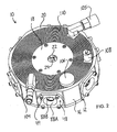
- Figure 1 shows an openable side of a first embodiment portable reciprocating compressor 10 of the present invention, which features a housing 12 comprising a removable cover 14 fastened in a sealing manner to an end of an annular cylindrical exterior wall 16.
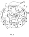
- Figure 2 shows a driving side of the first embodiment compressor 10 opposite the opening side.
- a circular cover 18 closes off the interior of the compressor housing 12 by sitting concentrically within the space surrounded by the annular cylindrical exterior wall 16 on a shoulder defined thereby to mate with an interior surface of the annular exterior wall 16 and sit flush with an end face 20 thereof.
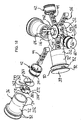
- a driving end 22 of a crankshaft 24 extends axially from within the cylindrical housing 12 through the second cover 18 for connection to a suitable drive source, such as a portable electric motor 26 as shown in Figure 3 .
- the first embodiment reciprocating compressor is of the radial type with a plurality of gas compressors 28 spaced about the crankshaft 24, each extending in a radial direction relative to a central axis of the housing 12 about which the annular exterior wall 16 extends.
- the portability of the compressor 10 is established, at least in part, by the fact that the housing 10 acts not only to support the gas compressors 28, but also to define a receiving compartment for containing gas compressed by the gas compressors.
- the housing may be considered to be a manifold, as it collects compressed air in its hollow interior from each gas compressor for discharge through a single outlet during use of the portable compressor.
- the housing 12 features an interior annular cylindrical wall 30 disposed concentrically within the exterior wall 16. Annular spacing between the two walls forms a receiving compartment in which the gas compressors 28 are disposed, extending radially between the two annular walls.
- the plurality of gas compressors includes six compressors arranged in diametrically opposed pairs and evenly spaced about the central axis of the housing 12.
- the space within the interior wall 30 defines a crankshaft compartment for housing components of the compressor's drive system.
- the interior wall 30 features round through-holes 32 each of which receives a drive end 34 of a cylinder liner 36 of a respective gas compressor 28.
- a valve end 38 of the cylinder liner 36 opposite the drive end 34 is received in a through-hole 40 provided in the exterior wall 16 axially aligned with the respective though-hole 32 in the interior wall 30.
- FIG. 5 shows one of the gas compressors 28 in an exploded state.
- each gas compressor 28 features a piston 42 disposed within and sealed to the cylinder liner 36 for movement therealong to compress gas contained therein.
- a connecting rod 44 features a piston end 46 having a through-hole provided therein to cooperate with a pin extending diametrically through the piston 42 to provide a pivotal connection between the piston and connecting rod 44 for pivotal motion within a plane parallel to the housing covers 14, 18.
- Connecting rod and piston connections of this type are well known to those of skill in the art.
- a driving end of the connecting rod 44 opposite the piston end 46 is adapted for pivotal motion within the same plane and connection to the crankshaft in a manner described herein further below.
- a cylinder head 48 is adapted for mounting by fasteners 49 on a flattened portion 50 of the exterior surface of the exterior annular cylindrical wall 16.
- the cylinder head 48 acts to hold the cylinder liner 36 in place within the opening 40 of the exterior wall 16 by blocking motion radially outward therefrom.
- the cylinder head 48 also provides an intake valve for controlling feeding of air from outside the housing 12 into the cylinder liner 36 for compression by the piston 42. This structure and workings of this valve are described herein further below.
- O-rings are disposed radially between the openings in the housing walls and the respective ends of the cylinder liner 36 to provide seals to ensure that gas contained within the receiving compartment defined between the housing walls 16, 30 will not leak into the crankshaft compartment within the interior wall 30 or to the exterior environment surrounding the housing 12.
- Such rings are commercially available and well-known to those of skill in the art.
- FIGS. 5 and 9 show master connecting rod 52 having a body portion 54 from which an integral rod or shaft portion 57 extends radially therefrom to a piston end 46 having the same structure as the pistons ends of the connecting rods 44 for connection to a respective piston.
- the body portion 54 of the master connecting rod 52 provides attachment points for the other connecting rods 44 so that connection of the master connecting rod 52 to the crankshaft 24 will thereby connect all of the connecting rods 44 to the crankshaft for actuation of the pistons 42.
- a driving end 56 of each connecting rod 44 acts as a key for receipt in a respective key-way of the body 54.
- the keys and key-ways are provided with smooth rounded surfaces to allow pivoting of the connecting rod 44 with respect to an axis of the keyway.
- the body portion 54 is provided with five key-ways in the form of cylindrical bores 58 overlapping with a periphery 60 of the otherwise cylindrical body portion 54.
- the result is a series of arcuate recesses into a peripheral wall of the body portion 54, each of which extends more than 180 degrees such that a linear distance between tips 62 of the recess is less than the diameter of the bore.
- the driving end 56 of each connecting rod is cylindrical and round and can be lifted or lowered into a respective recess and fit so as to be pivotal therein, but is too large to be pulled from the recess or key-way through the mouth defined by the opening between the tips 62.
- the key-ways extend parallel to a central axis of the body 54 along which a central bore 63 extends through the body 54 perpendicular to the parallel top and bottom faces thereof.
- This master connecting rod 52 provides the necessary pivotal connection to each connecting rod 44 in a relatively small space without the use of small pins (such as in an arrangement similar to that used to connect the rods and pistons) which may not provide adequate strength at the mounting points to avoid breakage and resulting detachment of the connecting rods.
- the connection point of each connecting rod is housed between portions of solid material of significant width or thickness, minimizing the chance of failure.
- This master connecting rod is of a construction that provides simplicity by avoiding use of pins, bushings and/or bearings for connection to the connecting rods while being robust yet small.
- the mating surfaces between the connecting rods 44 and the master connecting rod 52 should be smooth and hard to prevent vibration and wear.
- connection structure similar to that between the master connecting rod 52 and the connecting rods 44 may be adopted at the connection between the connecting rods 44 and pistons 42 by overlapping a cylindrical bore with the face of the piston nearest the master connecting rod to form an arcuate keyway extending across the piston into which the round cylindrical piston end 46 of the connecting rod can be slid before mounting the piston within the cylinder liner.
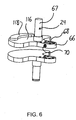
- the master connecting rod 52 is journaled on a crank pin 64 which extends through the central bore 63 passed the master connecting rod 52 on either side thereof for rigid connection to a respective crank cheek 66 from which extends a respective portion of the crankshaft journal 67.
- the crank cheek 66 features a receiving hole 68 for receiving the end of the crank pin 64 extending beyond the master connecting rod 52. Relative rotation between the crank cheek 66 and crank pin 64 may, for example, be prevented by a set screw 70 as shown in Figure 6 or by forming the cooperating crank pin 64 and receiving hole 68 to have the same straight-sided shape and size as shown in Figure 5 .
- crankshaft 24 is thus formed by the crankshaft journal 67 defining the axis of rotation and extending out of the compressor housing 12 through each cover thereof, the crank pin 64 offset from, or eccentric to, the crankshaft journal 67 and axis of rotation, and the two crank cheeks 66 connecting the opposite ends of the crank pin 64 to the crankshaft journal 67.
- crankshaft 24 With a motor 26 operatively connected to the drive end 22 of the crankshaft 24 extending from the compressor housing 12 as shown in Figure 3 , rotation of the crankshaft 24 causes the master connecting rod 52 to revolve around the crankshaft's axis of rotation due to the connection of the master connecting rod to the crank pin 64.
- the movement of the master connecting rod 52 along this circular path within the crankshaft compartment transfers rotational motion of the crankshaft 24 into linear displacement of the pistons 42 within the cylinder liners 26 by means of the connecting rods 44.
- the piston 42 of that gas compressor 28 moves radially outward toward the external wall 16 of the housing 12 to a maximum displacement.
- the piston is pulled back radially inward toward the interior wall 30 of the housing 12.
- the housing 12 defines a receiving compartment between the interior and exterior walls 30, 16 thereby contributing to the compressor's compactness and portability by doubling as both a housing, support or base for carrying the cylinders and a manifold for collecting compressed gas from all the cylinders within a single enclosure.
- the gas compressors 28 feature unique exhaust valves to take advantage of this arrangement.
- the gas compressors are supported on their own frame or housing and compressed gas is guided from the cylinders of the gas compressors to a receiving tank outside the housing through an exhaust valve in each cylinder head and a manifold connecting the exhaust valves and the tank.
- the external tank is eliminated and the compressed gas from the cylinder liners 36 is exhausted directly into the receiving compartment of the housing 12 by the unique exhaust valve arrangement.
- the exhaust valve of the first embodiment is disposed on the cylinder liner 36 within the receiving compartment.
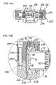
- Figure 7 shows a close-up view of a cylinder liner 36 near the valve end 38 thereof.
- the cylinder liner 36 features a cylindrical portion 72 of constant outer diameter which flares outward to an end portion 74 of greater diameter toward each of the valve and driving ends 38, 34 of the cylinder.
- the end portion 74 nearest the valve end 38 contains the unique exhaust valve.
- Ports 76 of the exhaust valve extending radially through the wall of the cylinder liner 36 in the end portion 74 and are spaced circumferentially thereabout. Disposed circumferentially about the end portion 74 to cover the exhaust ports 76 is a band 78 of liquid silicone rubber (LSR).
- LSR band 78 has a predetermined density, elasticity and size such that it stretches to fit snuggly over the cylinder liner 36 to seal off the exhaust ports 76 when the compressor 10 is not being run and also during the intake stroke of the gas compressor 28.
- the band 78 stretches radially outward from the cylinder liner 36 when exposed to higher pressure from inside the cylinder liner 36 through the exhaust ports 76 during the compression stroke of the gas compressor 28 to uncover these ports 76 and allow the exit of compressed gas from within the cylinder liner 36 into the receiving compartment of the housing.
- the band 78 then returns to its original position covering the exhaust ports 76 as the pressure inside the cylinder liner 36 decreases as a result of the passage of the compressed gas into the receiving compartment.
- the exhaust ports 76 and LSR band 78 thereby cooperate to form an exhaust valve operated by a difference in pressure between the cylinder liner interior and receiving compartment, the band 78 expanding about the cylinder liner to an open position during the compression stroke and then resiliently returning to a closed position to provide a seal between the cylinder liner interior and receiving compartment at all other times.
- LSR Low-density polystyrene
- the stretchable, flexible bands have an advantage over conventional metal reed valves in that they do not retain heat in the same way due to the significantly different material properties.
- These unique valves thus contribute to an improved efficiency of the compressor, as less of the energy used to open the valves is effectively lost through the creation of waste heat.
- a greater fraction of the energy applied to the valve actually contributes to its physical movement than in a conventional reed valve arrangement, so that less energy from the compressed air is wasted, i.e. less heat is produced, in the use of the unique compressor valve of the present invention than in the use of a conventional reed valve having the same opening pressure.
- the resilient, stretchable, flexible bands also have other advantages over conventional reed valves in that they don't corrode under exposure to moisture and don't experience the same bending fatigue that may lead to the failure of a reed valve to seat properly over the port opening or snapping off the reed.
- the use of LSR or similar material can thus improve the lifespan of a compressor and reduce the need or frequency of maintenance, repair and overhaul.
- liquid silicone rubber has a relatively high thermal stability, meaning that its material properties are relatively stable over the temperatures ranges experienced during typical use and storage of the compressor.
- two preventive measures are taken to ensure that the exhaust valve band 78 is not displaced axially along the cylinder liner 36 when it stretches about the liner during the compression stroke to open the exhaust ports 76.
- an exterior surface of the wall of the cylinder liner 36 features a recess 80 extending circumferentially about the end portion 74 nearest the valve end 38, effectively creating flanges 82 on either side of the recess 80.
- the exhaust ports 76 extending through the wall of the cylinder liner 36 are spaced along this recess and the band 78 is therefore positioned in the recess to cover them.
- the flanges 82 act to retain the band 78 in the recess 80, with the depth of the recess 80 being such that the band does not fully withdraw therefrom during exposure to the elevated pressures experienced during the compression stroke of the piston.
- the opening 40 in the exterior wall 16 of the housing 12 in which the valve end 38 and respective end portion 74 of the cylinder lining 36 are received is sized to have a diameter slightly larger than the end portion 74 to create and annular space between the cylinder liner 36 and exterior wall 16.
- the band 78 can expand into this annular space during the compression stroke, but is limited in this expansion by contact with the exterior wall 16 at the periphery of the opening 40. This prevents the band 78 from expanding far enough to slip over flanges 82 of the end portion 74 and risk being displaced from its port-covering axial position along the cylinder liner 36.
- the same unique valve structure is used to form the intake valve in the cylinder head 48.
- the cylinder head 48 features a cover portion 84 in the form of a flat plate for flush mounting against a respective flattened portion 50 of the exterior surface of the exterior housing wall 16.
- Fastener holes 86 are provided in corners of the cover portion 84 for receiving fasteners 49 that threadingly engage the exterior wall 16.
- An inlet 88 is recessed into the cover portion 84 from an outer face 90 thereof then continues passed an inner face 92 of the cover portion so as to form a cylindrical portion 94 projecting into the cylinder liner when the cylinder head 48 is mounted on the compressor housing 12.
- the external side of the inlet 88 i.e.
- the cylindrical portion 94 extending perpendicularly from the inner face 92 of the cover portion 84 features intake ports 96 extending radially through its wall and spaced circumferentially thereabout, creating passageways between the inlet 88 and the interior of the cylinder liner 36 when the cylinder head 48 is mounted.
- a flange 98 extends radially outward along the circumference of the cylindrical portion 94 at an end thereof opposite the cover portion 84, thereby creating a groove 100 between the flange 98 and inner face 92 for retaining another resilient band 78.
- the resilient band 78 acts similar to that of the exhaust valve, except it acts to let uncompressed gas enter the cylinder liner 36 for compression therein by the piston 42.
- the pressure difference between the surrounding environment and the cylinder liner interior reduces, causing the resilient band 78 to elastically return from its expanded open position to its closed position sealing of the intake ports 96.
- the build-up of pressure within the cylinder liner 36 therefore acts not only to stretch the band of the exhaust valve to open the exhaust ports but also to keep the band of the intake valve sealed over the intake ports.
- increased pressure within the cylinder liner of each gas compressor encourages expansion of the exhaust band but opposes expansion of the intake band.
- the characteristics of the bands are carefully chosen to provide the necessary function at the desired pressure levels of the compressor.
- gas passageways 102 are provided extending from within the receiving compartment between the interior and exterior walls 30, 16 of the housing 12 through the circular cover 18 for communication with a number of components supported on the housing exterior.
- these components may include male and female connection fittings 104, 105 for connection of discharge lines or air delivery hoses having male or female connectors thereon, a pressure gauge 106 for monitoring pressure within the receiving compartment or manifold and a depressurization valve 108 for manually emptying the receiving compartment of compressed gas.
- the compressor of the present invention may be equipped with other components used with conventional compressors.
- a pressure switch can be installed and wired between the battery and motor in a known manner to activate and deactivate the motor in response to the pressure measured within the receiving compartment or manifold to activate when additional compressed air is needed and deactivate when the pressure reaches a particular value.
- the pressure switch may be adjustable to allow adjustment of this value to control the discharge air pressure for a particular application.
- the removable and circular covers 14, 18 may feature cooling fins 110 to help dissipate heat produced during compression.
- Figure 3 shows the compressor coupled with a DC motor 26 at the driving end 22 of the crankshaft 24, the DC motor being powered by a schematically illustrated battery pack 112, which may be rechargeable.
- the motor 26 is angled at approximately 30 degrees to reduce the height to which the motor extends from the circular lid 18, therefore requiring a transmission 114 to transfer power from the motor to the crankshaft. It should be appreciated that the motor may be mounted in alternative orientations.
- the crankshaft extends outward from the housing through each cover so that a drive source can be connected to one end and a second compressor may be coupled to the other end for running of two or more compressors by the one drive source. It should be appreciated that the compressor would still be operable with only one end of the crankshaft extending outward from the housing for coupling with a drive source.
- crankshaft 24 drives the master connecting rod 52 about the rotational axis of the crankshaft by means of the crank pin 64.
- This rotational motion is transferred to linear displacement of the pistons 42 within the cylinder liners 36 by means of the connecting rods 44 (including the rod portion extending from the master connecting rod, or master connecting rod).
- the gas compressors 28 begin their respective compression strokes in a sequential fashion about the rotational axis, exhausting compressed gas into the receiving compartment one-after the other so as to effectively provide a near-continuous supply of compressed gas for discharge from the compressor 10.
- the intake strokes of the gas compressors 28 begin one after the other in a sequential fashion about the compressor, thereby effectively providing a near-continuous intake of gas from outside the compressor housing to prevent emptying of the receiving compartment.
- the compressor of the first embodiment is of the single-stage variety such that the air compressed within each cylinder liner is discharged directly to the receiving compartment rather than to another cylinder liner for further compression.
- each of the crank cheeks 66 extends passed the crankshaft journal 67 to form an integral counterweight 116 in the form a semi-circular lobe disposed diametrically opposite the master connecting rod 52 about the crankshaft's rotational axis.
- the counterweights help minimize vibration of the compressor 10 caused by eccentric rotation and reciprocation during operation.
- the counterweights may be provided with closable containers 118 thereon for storing weight-adding material to provide dynamic balancing by means of adding or removing such material to adjust the overall weight of the counterweights. Access to such containers is provided by means of the removable lid 14.
- the compressor is not oil-lubed, but rather includes a ring 120 of TeflonTM or other suitable low-friction material extending about the circumference of each piston 42 to decrease friction between the cylinder liner 36 and piston.
- Piston rings are used in a conventional manner to provide seals between the pistons and cylinder liners to prevent leakage of air from the gas compressors into the crankshaft compartment.
- a working prototype of the first embodiment was produced and coupled with a motor from a 28V cordless skill-saw, powered by a 28V lithium ion battery, by a custom made 1:1 drive-line and housing.
- the combined components weigh 5.44 kg (12 lbs) or less, dependant on materials used, and the prototype compressor is 17.78 cm (7 inches) in diameter and 6.35 cm (2.5 inches) thick.
- the 28-volt DC motor of the prototype develops 26.03 m/kg (465 in/lb) torque at 4200 rpm and the six pistons are 2.54 cm (1 inch) diameter with a 2.79 cm (1 - 1/4 inch) stroke.
- the design flow rate of the first embodiment prototype compressor is 198.22 l/min (7 CFM) at 482633 pa (70 PSIG) discharge.
- Another configuration has the motor positioned directly on top of the compressor resulting in a direct drive as opposed to the angled side line transmission.
- the first embodiment compressor may be provided as part of a compact system which can be easily carried by a user to power any number of pneumatic tools without any limitation of movement causes by power cords or air hoses.
- a compact system which can be easily carried by a user to power any number of pneumatic tools without any limitation of movement causes by power cords or air hoses.
- Such a system may include:
- the efficiency of the first embodiment compressor is such that ample amounts of compressed air are produced so quickly, that there is no need for a separate volumetric vessel (tank). Enough compressed air is produced on demand to operate most typical hand held air activated tools. Since this compressor is so efficient, it is therefore possible to drive it with a battery powered motor and achieve the same out put as one would expect from a power corded compressor. This being the case, it is therefore possible to combine the battery, motor and compressor, place them together into a wearable pack enabling an individual to freely roam while having ample compressed air at their finger-tips to operate any air tool which normally would only be driven by a stationary compressor via a long hose.
- Figures 10 to 12 show a second embodiment portable compressor 200 that is similar to the first embodiment portable compressor in that it features six cylinder liners 36 in a radial arrangement and a similar drive system featuring a motor 26 driving revolution of a master connecting rod 52 through a crank to effect sequential compression strokes of pistons 42 within the cylinder liners to discharge compressed gas into a common receiver.
- the second embodiment compressor 200 however is different from the first embodiment compressor in a number of ways.
- the second embodiment compressor 200 does not feature a unitary housing, but instead includes two separate housings.
- a receiver housing 202 defines a manifold into which compressed gas is exhausted from the cylinder liners 36 and is formed by a bottom half 203 and a top half 204 which mate together with the cylinder liners 36 disposed between them. With its halves mated together, the receiver housing 202 is annular in shape so as to define a central opening 206.
- a crank housing 208 is positioned within the central opening 206 of the receiver housing 202 and similarly has an annular shape defining a central opening, within which the body of the master connecting rod 52 and the crank pin are disposed.
- the cylinder liners 36 are received in openings 210 extending radially through the annular crank housing 208 from the central opening thereof toward the surrounding receiver housing 202.
- the cylinder liners 36 are sealed to the crank housing 208 at these openings therein and project radially outward from the crank housing 208 into the surrounding receiver housing 202.
- each cylinder liner 36 of the second embodiment compressor 200 do not flare outward to an increased diameter at opposite ends of a cylindrical portion 72.
- each cylinder liner 36 has a threaded portion 212 extending from the drive end 34 thereof nearest the central opening of the crank housing 208 so as to sealingly mate with corresponding threads provided on the respective opening 210 through the crank housing 208.
- the cylinder liner 36 also does not flare outward toward the valve end 38 opposite the drive end 34, but does feature pair of flanges 82 disposed on opposite sides of a recess 80 in its exterior surface.
- a plurality of exhaust ports 76 spaced about the central longitudinal axis of the cylinder extend radially through the cylinder liner 36 to communicate its hollow interior or cylindrical bore with its exterior.
- a resilient band of flexible material 78 is stretched about the cylinder liner 36 within the circumferential recess 80 to cooperate with the exhaust ports 76 in the same way as in the first embodiment to define an exhaust valve.
- the recess 80 of the exhaust valve has a tapered V-like shape narrowing inward from the radially outermost extent of the flanges 82 toward the hollow interior of the cylinder liner 36, as best shown in Figure 19 .
- the flexible resilient band 78 also tapers from a maximum width at its outermost surface 78a to a minimum width at its innermost surface 78b.
- the groove 80 and the resilient flexible band 78 taper at the same angle for an optimum fit and a tight seal when the band is not being stretched radially outward under the force of compressed air forced against it from the interior of the cylinder liner 36 through the exhaust ports 76.
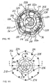
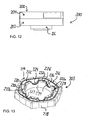
- Figure 10 shows the second embodiment compressor 200 without the top half 204 of the receiver housing 202 thereof so as to illustrate the mating side, or face, 214 of the bottom half 203 of the receiver housing, which is shown in isolation in Figure 13 .
- a series of fastener holes 216 extend into the bottom half 203 from the mating face 214 and are spaced thereabout adjacent the bottom half outer periphery 218. Spaced radially inward from the outer periphery 218 and the fastener holes 216 thereadjacent is an outer seal groove 220, extending fully about the central opening 206 of the receiver housing 202, in which an o-ring like seal is disposed to seal against a mating face of the top half 204 when the two halves of the receiver housing are mated together.
- a groove 222 recessed into the receiver housing bottom half 203 from the mating face thereof, also extending fully around the central opening 206.
- the groove 222 has a longitudinal path extending around the central opening 206 with the grooves outer edge 222a outlining a hexagonal type shape defining rounded corners 222b and six straight segments 222c of the groove, each straight segment extending perpendicular to the longitudinal axis of a respective one of the cylinder liners.
- At the midpoints of these six linear segments 223 are recessed portions 224 of the groove 222 dipping further downward into the bottom half 203 from the mating face 214 thereof than the rest of the groove 222.
- the groove 222 is of sufficient width at each of these recessed portions 224 to receive between its sides the two flanges 82 at the valve end 38 of each cylinder liner 36 forming the valve seat groove 80 that houses the resilient band of the exhaust valve.
- the groove 222 is less wide between the recessed portions 224 so that the flanges 82 will only seat properly within the recessed portions 224.
- Each recessed portion 224 of the groove 222 is arcuate in a vertical plane along the groove's longitudinal path around the central opening 206 so as to form a rounded cradle or seat in which the round flanges 82 of the cylinder liner 36 projecting radially outward from the cylindrical portion 72 thereof can rest.
- An inner portion 226 of the bottom half mating face 214 radially inward of the groove 222 at each of the recessed portions 224 thereof is similarly arcuately recessed, although at a smaller diameter, in a vertical plane to seat or cradle the cylindrical portion 72 of the respective cylinder liner 36 projecting from the flanged valve end 38 thereof into the central opening 206 of the receiver housing 202.
- One such seat or cradle for supporting the cylindrical portion of a respective cylinder liner is shown at 227 in Figure 13 .
- groove 222, outer seal groove 220 and outer periphery 218 is an inner seal groove 228 extending fully around the central opening 206 in the inner portion 226 of the mating face 214.
- the inner seal groove 228 is disposed radially outwardly relative to its position at the arcuate recesses in the inner portion 226 of the mating face 214 at which the groove 228 dips downward beneath the cylinders to form a seat or cradle 227.
- a second set of fastener holes 232 Spaced about the central opening 206 at these more outwardly disposed portions 230 of the inner seal groove 228 is a second set of fastener holes 232 positioned between these outward portions 230 and an inner periphery 234 of the bottom half 203 of the receiver housing and extending into the bottom half from the inner portion 226 of the mating face 214 thereof.
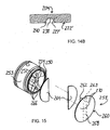
- Figure 14 shows the top half 204 of the receiver housing 202 in isolation before assembly with the bottom half 203.
- the top half 204 of the receiver has substantially the same structure as the bottom half.
- the top half 204 has a mating face 214' divided into inner and outer portions 226' and 236' by a groove 222' extending concentrically about the central opening 206 in a generally hexagonal shape with rounded corners.
- the groove 222' has arcuately recessed portions 224' centrally disposed along straight segments of the groove disposed between the rounded corners thereof to align with the recessed portions 224 of the bottom half 203.
- the outer portions 236, 236' of the mating faces 214, 214' are sealed together by a poured in place seal disposed within the outer seal groove 220 and the inner portions 226, 226' are sealed together between the cylinder liners 26 at the outwardly disposed portions 230 of the inner seal groove 228 by a poured in place seal disposed therein.
- the seal disposed in the inner seal groove 228 of the bottom half 203 of the receiver housing 202 also acts to seal the bottom half 203 to each of the cylinder liners 36 by engagement of the seal along each of the cradles or seats 227 with the bottom half of the cylindrical portion 72 of a respective cylinder liner 36.
- the top half 204 only needs to provide for sealing between itself and the cylinder liners 36.
- Six cylinder seal grooves 238 are provided on the top half 204 of the receiver housing 202 each extending along a respective one of the cradles 227' formed by a vertically disposed arcuate recess in the inner portion 226' of the mating face 214'.
- Each cylinder seal groove 238 extends at each of its ends slightly passed the edge 240 defined between the arcuate seat or cradle 227' and the neighbouring flat segment of the inner portion 226' of the mating face 214' to ensure that when the halves are assembled together with the cylinder liners 36 between them, no gaps exists between the receiver housing 202 and the cylinders at the cylinder seats or cradles 217, 217'.
- a poured in place seal is provided at each of the cylinder seal grooves 238.
- the piston liners 36 are threaded into engagement with the threaded openings provided in the outer periphery of the crank housing 208 as shown in Figure 10 .
- the pistons are mounted within the cylinder liners with their respective connecting rods attached and the slave connecting rods 44 are connected to the master connecting rod 52.
- Slave connecting rods are those that are not integral with the body of the 54 of the master connecting rod, but instead are pivotally connected thereto as disclosed for the first embodiment compressor, and the stem or shaft 57 integral with the body 54 being part of the single remaining connecting rod.
- a round disc-like cover 242 having an outer diameter approximately equal to that of the body 54 of the master connecting rod 52 is disposed thereatop and held in place by the head of the crank pin 64 extending downward therethrough on which the master connecting rod 52 is journaled.
- the crank pin passing therethrough is secured to the crank cheek 66 and integral counterweight 116 which in turn has its crank journal 67 coupled to the driveshaft of the motor 26, which in the second embodiment is a disc-shaped pancake or torque motor fixed to the bottom of the crank housing 208 to help minimize the dimensions of the compressor 200.
- crank housing 208 With the crank housing 208, the gas compressors and the drive system assembled, the crank housing 208 and attached motor 26 are lowered into the central opening 206 to seat the cylindrical portions 72 of the cylinder liners 36 within the cradles 227 defined by the arcuate recesses in inner portion 226 of the mating surface 214 and seat the flanges 82 of the cylinder liners 36 within the recessed portions 224 of the groove 222.
- This partial assembly is illustrated best by Figure 10 , in which the top half 204 of the receiver housing has yet to be installed.
- the top half 204 is lowered onto the bottom half 203, with the generally hexagonal shape of the outer periphery walls 218, 218' of the two halves 203, 204 allowing easy visual alignment thereof to dispose the cylinder cradles 227, 227' of the opposing halves in alignment above and below the cylinder liners 36.
- the fastener holes 216', 232' of the top half 204 of the receiver housing 202 are through holes while the fastener holes 216, 232 of the bottom half 203 are threaded blind holes.
- top half fastener holes 216', 232' align with the bottom half fastener holes 216, 232 so that threaded fasteners 244 can be passed into the bottom half 203 and secured thereto to clamp the two halves of the receiver housing together with the cylinder liners 36 between them.
- the grooves 222, 222' of the two halves are mirrored across the mating faces of the halves to form an enclosed channel 246 extending fully around the central opening 206 with the valve end 38 of each cylinder liner 36 disposed therein.
- the seal disposed in the outer seal groove 220 of the bottom half 203 provides an air tight seal between the outer portions 236, 236' of the mating faces 214, 214' around the entire channel 246 along the outer side thereof.
- the seal disposed in the inner seal groove 228 of the bottom half 203 seals between the two halves along the outwardly disposed portions 230 of the inner seal groove between the cylinder liners 36 as well as between the bottom half and each cylinder liner 36 along the arcuate recesses in the inner portion 226 of the mating surface forming the cylinder cradles 227.
- the seal disposed in the cylinder seal grooves 238 of the top half 204 complete the sealing off of the channel 246 by providing an air tight seal between the top half 204 and each of the cylinder liners 36.
- the channel 246 thus forms a receiver, or collector or manifold, that extends about each and all of the cylinder liners 36 to sealingly enclose the valve ends 38 thereof which include the exhaust valves formed at each cylinder by the exhaust ports 76 extending radially through the cylinder liner 36 between the flanges 82 thereof and the resilient band 78 extending about the cylinder liner 36 between the flanges 82.
- gas passageways 102 are provided extending through the bottom half 203 parallel to the axis about which the annular receiver housing 102 extends.
- the bores defining these passageways pass through an exterior face 248 of the bottom half 203 opposite the mating surface 214 thereof. Just as in the first embodiment compressor, these passageways are threaded to provide sealed coupling with connection fittings, a pressure gauge, a depressurization valve or a pressure switch.
- the receiver housing 102 provides a significantly smaller manifold or receiver for collecting compressed air from each of the cylinders for discharge through a common outlet, such as a male or female connection fitting coupled to a respective one of the gas passageways 102 for connection to an air delivery hose adapted for connection to a pneumatic tool.
- a common outlet such as a male or female connection fitting coupled to a respective one of the gas passageways 102 for connection to an air delivery hose adapted for connection to a pneumatic tool.
- the second embodiment compressor 200 features a different intake arrangement than the first embodiment compressor. Rather than having intake valves provided in cylinder heads mounted sealed to the valve ends of the cylinder liners, the second embodiment features intake valves formed on the pistons 42.
- Two intake ports 250 extend axially through the piston 42 on opposite sides of a central span 252 extending diametrically across the round cylindrical annular wall 253 defining the periphery of the piston 42.
- Each intake port is of a somewhat semi-circular cross sectional shape with a diameter slightly less than that of the piston so as to take up a significant portion of the piston's cross sectional area while leaving the central span intact between the two ports.
- An o-ring groove 256 in the face 254 of the piston 42 extends around both of the intake ports 250 to receive a conventional o-ring to provide proper sealing of the intake ports 250 when closed.
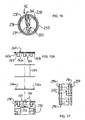
- a flap of flexible resilient material, such as LSR, 258 is shaped to define a circular disc 260 having three cylindrical projections 262 of equal length spaced along a linear strip 263 formed on a face of the disc and extending diametrically thereacross to project from the strip in a perpendicularly away from the disc face.
- each plate 264 is shaped liked the respective portion of the flap disc 260 to which it is bonded, such that the arcuate edge of the plate is substantially flush with the periphery of the flap disc 260.
- the projections 262 are of sufficient length to project from the strip 263 to engage with three corresponding blind holes 266 extending into the central span 252 of the piston 42 from the face 254 thereof at positions spaced along the diametrical span 252 with the same center to center spacing as the projections.
- the linear strip 263 and the diametrically extending portion of the disc 260 of the flexible flap 258 along which the strip 263 extends define a fixed portion 268 of the flap 258 retained in a generally fixed position relative to the piston face 254 by engagement of the projections 262 and blind holes 266.
- the remainder of the disc 260 on each side of this fixed portion defines a movable portion 270 of the disc 260 extending laterally therefrom and is movable relative to the fixed portion in a pivotal-like motion resulting from bending of the flexible disc 260 along the boundary between the fixed and movable portions, in other words along the edge 272 between the linear strip 263 and the disc face on which the strip is formed.
- the movable portions 270 are movable relative to the fixed portion 268 from a closed position in which they are coplanar, in other words where together with the fixed portion 268 they form the flat disc 260, to an open position in which they each extend out of the plane of the fixed portion 263 away from the piston face 254.
- the plate 264 fixed to each movable portion 270 of the disc rests flush against the o-ring seal 256a disposed in the o-ring seal groove 256 along the arcuate portion of the respective somewhat semicircular port 250 for covering or closing thereof.
- the plate 264 is at least partially lifted from this flush contact with the seal 256a to open or uncover the port to allow airflow therethrough.
- the linear strip 263 is stepped at each end from a central portion 263a, from which the projections 262 extend, to a shorter end portion 263b of smaller thickness equal to that of each metal plate 264.
- the central portion 263a will sit flush against the face of the central span 252 of the piston over its full length from the inside perimeter of the annular o-ring seal groove 256 at one end of the central span 252 to a diametrically opposite point on the inside perimeter of the o-ring seal groove 256.
- the difference in thickness between the central portion 263a of the strip 263 and the end portion 263b is equal to the distance by which the o-ring seal 256a received in the o-ring seal groove 256 projects from the piston face 254 in a direction perpendicular thereto.
- the end portions 263b of the strip thus rest flush with the face of the o-ring seal 256a projected slightly past the piston face 254 from the o-ring seal groove 256 therein. Spanning the full length of the central span 252, the ends of the central portion 263a of the strip 263 abut against inner periphery of the o-ring seal 256a.
- the disc 260, the strip 263 and the projections 262 are an integral unit that may be possible to mold into place on the piston.
- two temporary elongate linear barriers may be placeable along the central span 252 of the piston on the opposite sides thereof, each being equal in height to an o-ring seal 256a disposed in the o-ring seal groove 256, to form parallel chords of the circle defined by the o-ring seal.
- Each metal plate 264 can then be set atop the barrier and arcuate portion of the o-ring seal on the respective side of the central span.
- the LSR entering the area between the barriers along the central span 252 forms the strip 263, the barriers preventing the LSR from flowing therepast beneath the plates and into the ports.
- LSR flowing from this area between the barriers down further into the blind holes 266 in the central span 525 forms the projections, the holes each being threaded so that when the LSR dries, interference between the periphery of each projection with the threads of the respective hole 266 prevent linear withdrawal to secure the flap to the piston.
- the threads within each hole or bore 266 act as barbs projecting into the periphery of the respective projection 262 of the flap. Rotation of a projection to withdraw from the respective threaded hole or bore is prevented by the use of multiple projection and threaded hole pairings.
- a thin layer formed over the strip once the area between the barriers is filled defines the disc 260.
- Forming separate seal grooves around the two ports, rather than the single o-ring seal groove 256 extending about both ports, may improve the ease of molding the flap onto the piston by preventing leakage of LSR into the ports without the need for some temporary measure for this purpose during molding.
- the flap 258 may be formed and mounted on the piston in a two-stage molding process in which the disc 260 and the strip 263 are formed on the two metal plates 264 held positioned relative to one another in a mold as though in their in-use closed position (co-planar with their straight sides spaced from one another by a distance corresponding to the strip 263 to be formed), the mold shaped such that LSR flowed between the plates will form the strip 263 and LSR flowed onto the faces of the plates will form the disc thereatop integral with the strip.
- the mold would feature three projections spaced along the strip-forming portion therein to produce three through holes spaced along the strip and passing through the strip and the disc integral therewith.
- the second stage involves fixing these components in place on the piston so that the three holes in the disc and strip structure align with the blind holes 266 in the central portion 252 of the piston and the metal plates 264 sitting flush on the o-ring seal already installed on the piston.
- LSR is then poured or injected into the blind holes 266 in the piston through the corresponding holes in the strip and disc formed during the first stage, this LSR drying to form the same connection with the piston as described above and also bonding to the previously formed LSR disc and strip.
- threaded fasteners may be passed through the disc 260 to engage the threaded holes in the piston.
- a metal strip of material may be applied on a side of the disc opposite the piston for passage of the fasteners through the metal strip and the flexible flap to better distribute pressure applied to the disc by the fastener heads along the fixed portion to help keep it stationary.
- a lid 274 engagable to the crank housing 208 proximate the top face 276 thereof has openings 278 therethrough to allow airflow into the hollow space, or crank chamber, defined by the annular crank housing 208 containing components of the drive system.
- the lid is disc shaped having four tabs 280 projecting radially outward therefrom at evenly spaced points about its circumference.
- corresponding notches 282 extend radially into the inner periphery of the crank housing 208, each having a respective slot extending from a side thereof below and parallel to the top face 276 such that upon lowering of the lid slightly into the crank chamber to rest the tabs 280 come within the notches 282 open at the top surface 276, the lid 274 can be rotated about its axis to slide and snap the tabs 280 into the slots. This prevents linear withdrawal of the lid 274 upward from the crank housing 208 without a manual unlocking rotation of the lid to return the tabs 280 to the notches 282 open at the top surface of the 276 of the crank housing 208.
- the large ports and LSR flap should allow significant volumes of compressed air to be produced relatively quickly from the plurality of cylinders, with relatively little heat retention, to build up sufficient pressure for powering rapid repetitive actuation of the pneumatic tool. It is also thought that these unique valves may be able to overcome the limitations on the port size of conventional reed valves relative to the achievable compression, and may therefore have potential for use in higher pressure applications.
- a flexible resilient flap having a movable portion extending from a fixed portion to carry a separate metal plate attached thereto for covering a respective port reduces the likelihood of premature failure compared to metal or fiberglass reed valves which may fatigue and fail to seat properly or snap off, as all of the flexing or bending is handled by the LSR or other suitable flexible material, and not by the metal plates.
- the metal plates by having significantly more rigidity than the flexible flap, each provide a consistently flat surface for sealing with the o-ring and limit the flexing or bending of the flap to the border between the fixed and movable portions to allow only the desired pivotal-like motion thereabout.
- the LSR flap of the second embodiment intake valves reduce waste energy compared to heat-retaining conventional reed valves and offer improved resistance to stress-induced failure.
- the central span 252 spans the full interior diameter of the annular piston wall 253 only partially along the piston's length from the face 254, as shown in Figure 17 , so as to provide room for pinning of the connecting rod 44 inside the annular 253.
- a seal ring groove 290 and a rider band groove 292 are provided in the exterior surface of the annular piston wall 253, extending circumferentially thereabout and spaced along piston's length, to support a seal ring and a rider band, such as a friction reducing Teflon piston ring, proximate the face 254 nearest the valve end 38 of the cylinder liner 36 and the opposite connecting rod end 294 of the piston respectively.
- a seal ring groove 290 and a rider band groove 292 are provided in the exterior surface of the annular piston wall 253, extending circumferentially thereabout and spaced along piston's length, to support a seal ring and a rider band, such as a friction reducing Teflon piston ring, proximate the face 254 nearest the valve end 38 of the cylinder liner 36 and the opposite connecting rod end 294 of the piston respectively.
- the second embodiment compressor 200 may be mounted within a backpack for carrying on the back of a user along with a rechargeable battery pack. It should be appreciated that the compressor 200 may be adapted to have the batter pack relaeasably mounted directly thereto, with wiring of the electrical supply, motor and a pressure switch being well known to those of skill in the art. With the compressor, including the motor, and battery pack provided in such a compact unit, especially with the use of a relatively thin and flat pancake or torque motor, a full size pack may not be necessary to easy carrying by a user. For example, the compressor may be equipped with a tightenable strap for wearing about the waist or leg of a user.
- the battery pack may be connected to the compressor through openings in such a meshed sack or container through the openings therein, to allow easy and quick replacement of a rechargeable battery without having to first remove the entire assembly from its carrying container.
- Each of the three embodiments described above provides a compressor having more than two gas compressors radially disposed about the driveshaft within a common plane so as to keep the height or thickness of the unit down.
- the compactness of each portable unit is improved over conventional portable compressors by having the rigid base or housing that supports the cylinders also act as the manifold for collecting compressed gas from each cylinder into the same common receiving space.
- Suitable materials for the compressor embodiments described above will be appreciated by those of skill in the art and include metals and plastics, with plastics or lighter weight metals such as aluminum helping contribute to the portability of the compressor by keeping its overall weight down.
- this portability does not rely entirely on having the cylinder liners disposed partly within the manifold itself or on the use of the advantageous, unique compressor valves disclosed herein, although these features do contribute a significantly compact and protected substantially enclosed unit.
- any of the compressor embodiments described herein above may be additionally include a built-in regulator valve installed in a discharge port or outlet of the compressor to control the pressure of gas delivered by an air hose coupled to the compressor.
Landscapes
- Engineering & Computer Science (AREA)
- General Engineering & Computer Science (AREA)
- Mechanical Engineering (AREA)
- Compressor (AREA)
- Compressors, Vaccum Pumps And Other Relevant Systems (AREA)
Priority Applications (1)
| Application Number | Priority Date | Filing Date | Title |
|---|---|---|---|
| EP18192409.3A EP3431763A1 (en) | 2006-06-08 | 2007-06-08 | Reciprocating compressor or pump and a portable tool powering system including a reciprocating compressor |
Applications Claiming Priority (2)
| Application Number | Priority Date | Filing Date | Title |
|---|---|---|---|
| US80421606P | 2006-06-08 | 2006-06-08 | |
| PCT/CA2007/000990 WO2007140596A1 (en) | 2006-06-08 | 2007-06-08 | Reciprocating compressor or pump and a portable tool powering system including a reciprocating compressor |
Related Child Applications (1)
| Application Number | Title | Priority Date | Filing Date |
|---|---|---|---|
| EP18192409.3A Division EP3431763A1 (en) | 2006-06-08 | 2007-06-08 | Reciprocating compressor or pump and a portable tool powering system including a reciprocating compressor |
Publications (3)
| Publication Number | Publication Date |
|---|---|
| EP2029894A1 EP2029894A1 (en) | 2009-03-04 |
| EP2029894A4 EP2029894A4 (en) | 2014-06-25 |
| EP2029894B1 true EP2029894B1 (en) | 2018-09-05 |
Family
ID=38801003
Family Applications (2)
| Application Number | Title | Priority Date | Filing Date |
|---|---|---|---|
| EP07719906.5A Not-in-force EP2029894B1 (en) | 2006-06-08 | 2007-06-08 | Reciprocating compressor or pump |
| EP18192409.3A Withdrawn EP3431763A1 (en) | 2006-06-08 | 2007-06-08 | Reciprocating compressor or pump and a portable tool powering system including a reciprocating compressor |
Family Applications After (1)
| Application Number | Title | Priority Date | Filing Date |
|---|---|---|---|
| EP18192409.3A Withdrawn EP3431763A1 (en) | 2006-06-08 | 2007-06-08 | Reciprocating compressor or pump and a portable tool powering system including a reciprocating compressor |
Country Status (15)
| Country | Link |
|---|---|
| US (6) | US7959415B2 (enExample) |
| EP (2) | EP2029894B1 (enExample) |
| JP (1) | JP5646171B2 (enExample) |
| KR (1) | KR101432324B1 (enExample) |
| CN (1) | CN101501338B (enExample) |
| AU (1) | AU2007257159B2 (enExample) |
| BR (1) | BRPI0712140B1 (enExample) |
| CA (3) | CA2866734C (enExample) |
| ES (1) | ES2700698T3 (enExample) |
| MX (1) | MX2008015468A (enExample) |
| NO (1) | NO344515B1 (enExample) |
| RU (1) | RU2451834C2 (enExample) |
| TW (1) | TWI427218B (enExample) |
| UA (1) | UA101467C2 (enExample) |
| WO (1) | WO2007140596A1 (enExample) |
Families Citing this family (58)
| Publication number | Priority date | Publication date | Assignee | Title |
|---|---|---|---|---|
| US8893706B2 (en) * | 2006-12-12 | 2014-11-25 | Enerco Group, Inc. | Forced air heater including on-board source of electric energy |
| US20090255506A1 (en) * | 2008-04-14 | 2009-10-15 | Walker S Paul | Rotary internal combustion engine |
| US8671569B1 (en) * | 2009-04-29 | 2014-03-18 | Superior Transmission Parts, Inc. | Accumulator bore repair kit and replacement pistons |
| WO2011073464A1 (es) * | 2009-12-17 | 2011-06-23 | Electro Ad, S.L. | Bomba de vacío, presión o líquidos |
| US9221112B2 (en) | 2010-03-10 | 2015-12-29 | Milwaukee Electric Tool Corporation | Motor mount for a power tool |
| US20110238490A1 (en) * | 2010-03-25 | 2011-09-29 | Microsoft Corporation | Auction flighting |
| DE102010013756A1 (de) * | 2010-03-31 | 2011-10-06 | Andreas Stihl Ag & Co. Kg | Handgeführtes Arbeitsgerät |
| US20120045347A1 (en) * | 2010-08-22 | 2012-02-23 | Dvorak Steven G | Air Compressor |
| DE102010035860A1 (de) * | 2010-08-30 | 2012-03-01 | Daimler Ag | Brennstoffzellensystem |
| JP5826614B2 (ja) * | 2011-11-22 | 2015-12-02 | 株式会社マキタ | エアコンプレッサ |
| JP5373155B1 (ja) | 2012-06-20 | 2013-12-18 | シナノケンシ株式会社 | 圧縮機又は真空機 |
| JP5492256B2 (ja) * | 2012-06-21 | 2014-05-14 | シナノケンシ株式会社 | 圧縮機又は真空機 |
| DE102015206868A1 (de) | 2014-04-17 | 2015-10-22 | Continental Teves Ag & Co. Ohg | Pleuellagerung für einen Luftverdichter eines Luftfedersystems sowie Kolbenkompressor |
| US9707674B2 (en) * | 2014-07-24 | 2017-07-18 | Taizhou Dajiang Ind. Co., Ltd. | Cylinder cover for steam powered nailing guns |
| CN104179659A (zh) * | 2014-08-11 | 2014-12-03 | 宁波泰源工量具有限公司 | 一种多缸体的气泵 |
| CN107250575A (zh) * | 2015-01-22 | 2017-10-13 | Spx流动技术诺德斯泰特股份有限公司 | 具有曲柄驱动装置的流程泵 |
| MX387588B (es) * | 2015-04-09 | 2025-03-18 | Anthony Steven Froehler | Sistema de accionamiento para bombas de inyección de productos químicos y compresores de aire instrumental. |
| US11002268B2 (en) * | 2015-07-27 | 2021-05-11 | Cobham Mission Systems Davenport Lss Inc. | Sealed cavity compressor to reduce contaminant induction |
| US9702359B2 (en) | 2015-09-01 | 2017-07-11 | TSC Manufacturing and Supply, LLC | Pump casing |
| US10408201B2 (en) * | 2015-09-01 | 2019-09-10 | PSC Engineering, LLC | Positive displacement pump |
| RU172521U1 (ru) * | 2015-09-30 | 2017-07-11 | Общество с ограниченной ответственностью "Тегас" | Цилиндр двойного действия |
| WO2017078388A1 (ko) * | 2015-11-03 | 2017-05-11 | 강석재 | 누름자 조절장치 및 이를 갖는 매니폴드 게이지 세트 |
| RU2018144251A (ru) * | 2016-05-17 | 2020-06-17 | Гал ГОЛДНЕР | Компрессор |
| IT201600108856A1 (it) * | 2016-10-27 | 2018-04-27 | Dropsa Spa | Pompa pneumatica di lubrificante ad immersione |
| US20200173430A1 (en) * | 2017-04-28 | 2020-06-04 | Actuant Corporation | Battery-powered pump |
| US11162482B2 (en) * | 2017-04-28 | 2021-11-02 | Graco Minnesota Inc. | Portable hydraulic power unit having a pump fixed to an exterior side of a fluid supply tank |
| WO2019007480A1 (de) * | 2017-07-04 | 2019-01-10 | Vetter Gmbh | Pumpeneinheit |
| CN108194307A (zh) * | 2018-02-11 | 2018-06-22 | 泓道(上海)科技有限公司 | 活塞式空气压缩机 |
| CN108194329A (zh) * | 2018-02-11 | 2018-06-22 | 泓道(上海)科技有限公司 | 空气压缩设备及包含其的空气压缩系统 |
| CN108194328A (zh) * | 2018-02-11 | 2018-06-22 | 泓道(上海)科技有限公司 | 缸体总成及包含其的空气压缩设备 |
| GB2578127B (en) * | 2018-10-17 | 2022-11-23 | Vectair Systems Ltd | Fluid dispenser |
| DE102019215023A1 (de) * | 2019-09-30 | 2021-04-01 | Robert Bosch Gmbh | Luftkompressionsvorrichtung |
| CN110905761A (zh) * | 2019-12-11 | 2020-03-24 | 安徽冠东科技有限公司 | 一种扁式环形微型气泵 |
| CN111188750A (zh) * | 2020-02-21 | 2020-05-22 | 广州市安途电器有限公司 | 一种汽车充气泵 |
| JP2022002622A (ja) * | 2020-06-23 | 2022-01-11 | コニカミノルタ株式会社 | 超音波診断装置 |
| US12023300B2 (en) * | 2020-06-29 | 2024-07-02 | Hill-Rom Services Pte. Ltd. | Rotational high frequency chest wall oscillation pump |
| CN111779669A (zh) * | 2020-08-04 | 2020-10-16 | 赣州市闻誉科技有限公司 | 一种用于低洼的自吸式抽水泵 |
| CN112066126B (zh) * | 2020-09-02 | 2022-03-04 | 蓝箭航天空间科技股份有限公司 | 一种用于供气连接器中的地面球锁 |
| KR102436042B1 (ko) * | 2020-12-18 | 2022-08-24 | 엘지전자 주식회사 | 탄성체 및 이를 포함한 리니어 압축기 |
| TWI792235B (zh) * | 2021-03-22 | 2023-02-11 | 鄭家俊 | 內燃機增壓系統 |
| CN113266610B (zh) * | 2021-04-22 | 2023-05-05 | 华侨大学 | 采用液控单向阀配流的径向柱塞液压装置及工作方法 |
| CN113203337B (zh) * | 2021-04-23 | 2023-07-21 | 安徽工程大学 | 一种汽车前翼子板与前大灯加固连接件的检具 |
| US12135021B2 (en) | 2021-08-17 | 2024-11-05 | Koninklijke Philips N.V. | Suspension system, compressor assembly and portable oxygen concentrator |
| US11661848B2 (en) * | 2021-08-29 | 2023-05-30 | Itt Manufacturing Enterprises Llc | Four piston scotch yoke actuator |
| CN113958478A (zh) * | 2021-10-29 | 2022-01-21 | 宁波瑞工自控设备有限公司 | 一种计量泵 |
| CN114483521B (zh) * | 2022-02-12 | 2024-06-28 | 浙江凯途机电有限公司 | 全无油压缩机 |
| JP7797954B2 (ja) | 2022-04-28 | 2026-01-14 | マックス株式会社 | 気体圧縮機 |
| US20230358225A1 (en) * | 2022-05-06 | 2023-11-09 | E. Mishan & Sons, Inc. | Portable tire inflator |
| CN114754004B (zh) * | 2022-05-07 | 2024-07-02 | 郑州轻工业大学 | 一种滑槽回转式补气增焓压缩机及其热泵系统 |
| CN114856958A (zh) * | 2022-05-17 | 2022-08-05 | 国网江苏省电力有限公司超高压分公司 | 变电站高压带电设备可移动式智能降温系统的制冷压缩机 |
| EP4296511B1 (en) * | 2022-06-24 | 2024-12-04 | Gentilin Srl | Reciprocating volumetric compressor structure |
| CN115573881B (zh) * | 2022-11-03 | 2025-11-18 | 珠海格力电器股份有限公司 | 流路组件和往复式压缩机 |
| CN116044704A (zh) * | 2023-01-09 | 2023-05-02 | 湖南省瑞柯电子科技有限公司 | 星型活塞式空压机 |
| BE1031580B1 (nl) * | 2023-04-28 | 2024-12-10 | Atlas Copco Airpower Nv | Koeling van een batterijpak van een elektrisch aangedreven mobiele compressor |
| DE102023119382A1 (de) * | 2023-07-21 | 2025-01-23 | Viessmann Climate Solutions Se | Kältekreisvorrichtung und wärmepumpe |
| DE102023119386A1 (de) * | 2023-07-21 | 2025-01-23 | Viessmann Climate Solutions Se | Kältekreisvorrichtung und wärmepumpe |
| DE102023134427A1 (de) * | 2023-12-08 | 2025-06-12 | Rapa Automotive Gmbh & Co. Kg | Druckluftversorgungseinheit mit sternverdichter |
| CN120007437A (zh) * | 2025-03-17 | 2025-05-16 | 北京理工大学长三角研究院(嘉兴) | 高速内燃机的自平衡装置 |
Family Cites Families (126)
| Publication number | Priority date | Publication date | Assignee | Title |
|---|---|---|---|---|
| US1320792A (en) * | 1919-11-04 | noguera and j | ||
| US600258A (en) * | 1898-03-08 | cramer | ||
| US167604A (en) | 1875-09-14 | Improvement in valves for pneumatic pumps | ||
| US699570A (en) * | 1902-01-08 | 1902-05-06 | George W Rhine | Air-compressor. |
| US1368315A (en) * | 1917-08-22 | 1921-02-15 | Baltimore Oil Engine Company | Valve |
| US1437184A (en) * | 1919-11-21 | 1922-11-28 | Frank S Bowman | Air pump |
| US1696013A (en) * | 1926-11-11 | 1928-12-18 | James E Reid | Air compressor for dental and other purposes |
| US1654893A (en) * | 1927-02-10 | 1928-01-03 | Roy J Meyers | Compressor |
| US1818413A (en) * | 1928-03-21 | 1931-08-11 | Samuel W Luitwieler | Compressor |
| US1957435A (en) * | 1928-12-12 | 1934-05-08 | Siemens Ag | Pumping mechanism |
| US1791672A (en) * | 1929-03-11 | 1931-02-10 | Frederick P Hinckley | Air compressor |
| US1842027A (en) * | 1930-08-06 | 1932-01-19 | Breuer Electric Mfg Co | Portable air compressor |
| US1854773A (en) * | 1930-11-22 | 1932-04-19 | Fort Wayne Engineering And Mfg | Pump |
| US1914141A (en) * | 1931-05-13 | 1933-06-13 | David M Fetters | Power transmitting device |
| US2023609A (en) * | 1932-05-28 | 1935-12-10 | Sven T Nelson | Pump and motor structure |
| US1964679A (en) * | 1932-09-28 | 1934-06-26 | Garland P Springfield | Compressor |
| US2053593A (en) * | 1933-10-02 | 1936-09-08 | Ziska Adam | Air compressor |
| US2151402A (en) * | 1937-03-15 | 1939-03-21 | Carl E Burch | Air compressor |
| US2309551A (en) * | 1939-11-03 | 1943-01-26 | Automotive Prod Co Ltd | Pump |
| US2255852A (en) * | 1940-04-19 | 1941-09-16 | Radial Pump And Compressor Com | Pump assembly |
| US2319718A (en) * | 1940-09-06 | 1943-05-18 | John W Brooks | Air compressor |
| US2255851A (en) * | 1940-10-21 | 1941-09-16 | Radial Pump And Compressor Com | Pump assembly |
| US2284645A (en) * | 1941-01-27 | 1942-06-02 | Duffy Charles Hugh | Air pump or compressor |
| US2466215A (en) * | 1944-08-17 | 1949-04-05 | C Roy Miller | Radial pump |
| US2544055A (en) * | 1946-12-11 | 1951-03-06 | Franklin E Staats | Variable throw crankshaft piston type radial pump |
| US2621607A (en) * | 1947-01-03 | 1952-12-16 | Trapp George Joseph | Pump |
| US2668004A (en) * | 1948-03-02 | 1954-02-02 | American Brake Shoe Co | Compressor |
| US2516864A (en) * | 1948-08-24 | 1950-08-01 | Gen Electric | Method of making hose from elastomeric composition |
| DE805005C (de) | 1948-10-10 | 1951-05-04 | Albert Doering G M B H | Druckventil fuer Fluessigkeits-Kolbenpumpen |
| US2568357A (en) * | 1948-11-26 | 1951-09-18 | Tony M Moulden | Variable-displacement radial-piston pump |
| US2725182A (en) * | 1951-02-01 | 1955-11-29 | David L Spriggs | Air compressor |
| US2790597A (en) * | 1954-06-14 | 1957-04-30 | Hauck Mfg Co | Pump |
| US2759665A (en) * | 1954-10-28 | 1956-08-21 | Portable Electric Tools Inc | Air compressors |
| US2895001A (en) * | 1955-07-05 | 1959-07-14 | Dayton Rubber Company | Combination hose and electrical conductors |
| US2917568A (en) * | 1956-10-25 | 1959-12-15 | Dayton Rubber Company | Oxygen delivery tube |
| BE563400A (enExample) * | 1956-12-21 | |||
| US3035757A (en) * | 1958-03-17 | 1962-05-22 | Westinghouse Air Brake Co | Apparatus for controlling a plurality of compressors |
| US2998474A (en) * | 1958-09-29 | 1961-08-29 | Hoover Co | Electrically conductive extensible hose |
| NL112629C (enExample) * | 1960-04-14 | |||
| US3085219A (en) * | 1960-06-02 | 1963-04-09 | Perfecting Service Company | Improved composite fluid and electrical coupling |
| NL273812A (enExample) * | 1961-02-27 | |||
| US3163707A (en) * | 1962-12-27 | 1964-12-29 | Ralph E Darling | Non-stretch flexible tube with conductors therein |
| US3198873A (en) * | 1963-05-20 | 1965-08-03 | Atlas Copco Ab | Flexible conduits having electrical conductors therein |
| US3366073A (en) * | 1965-12-10 | 1968-01-30 | Dowty Technical Dev Ltd | Hydraulic displacement devices |
| US3570372A (en) * | 1968-11-29 | 1971-03-16 | John F Campbell | Radial pump with hydrostatic load balance |
| US3571486A (en) * | 1969-02-07 | 1971-03-16 | Walter T Kennedy | Pressurized communication cable and system |
| GB1330902A (en) * | 1970-01-21 | 1973-09-19 | Hepworth & Grandage Ltd | Pistons and connecting rods |
| US3779672A (en) * | 1970-03-03 | 1973-12-18 | W Schroeder | Air compressor |
| US3673541A (en) * | 1970-08-06 | 1972-06-27 | Amp Inc | Composite electrical and fluid or air connector |
| US3746832A (en) * | 1971-07-29 | 1973-07-17 | Dover Corp | Arc welding gun unitized gas hose and electrical control cord |
| US3924968A (en) | 1972-07-27 | 1975-12-09 | Gen Motors Corp | Radial compressor with muffled gas chambers and short stable piston skirts and method of assembling same |
| DE2256231C3 (de) * | 1972-11-16 | 1980-06-12 | Reima-Reinigungsmaschinen Gmbh U. Co Kg, 7251 Moensheim | Biegeelastischer Saugschlauch |
| US3845450A (en) * | 1972-12-26 | 1974-10-29 | Bendix Corp | Underwater electrical connector |
| IT986948B (it) * | 1973-05-24 | 1975-01-30 | Pecorari F | Dispositivo di spinta alternativa nei motori e nelle pompe oleodina mici radiali |
| US3981229A (en) * | 1973-07-11 | 1976-09-21 | Midland-Ross Corporation | Gas powered motor |
| US3961868A (en) | 1974-02-21 | 1976-06-08 | Thomas Industries, Inc. | Air compressor |
| US3931554A (en) | 1974-08-13 | 1976-01-06 | Spentzas Nikolaos E | Reciprocating motor-compressor system |
| US3965756A (en) * | 1975-03-14 | 1976-06-29 | Valles Alfredo E | Multi-speed and leverage motor |
| US4105371A (en) * | 1976-10-15 | 1978-08-08 | General Motors Corporation | Cam driven compressor |
| US4094567A (en) * | 1977-01-05 | 1978-06-13 | The Hansen Manufacturing Company | Combination quick connect-disconnect pneumatic/electrical coupling |
| DE2719851C3 (de) * | 1977-05-04 | 1982-01-28 | Gummi-Roller Gmbh & Co, 6236 Eschborn | Monoschlauch mit herausgeführten elektrisch leitenden Adern und Verfahren zum Herausführen der Adern aus dem Monoschlauch |
| IT1086329B (it) * | 1977-05-26 | 1985-05-28 | Riva Calzoni Spa | Dispositivo di aggancio dei pistoni al rotore in un motore idraulico a pistoni radiali |
| US4179244A (en) * | 1977-05-31 | 1979-12-18 | Hargraves Aerobic Systems, Inc. | Rotary low pressure air displacement pump |
| US4230899A (en) * | 1978-08-21 | 1980-10-28 | Shiro Kanao | Electroconductive hose for cleaner |
| US4273519A (en) * | 1978-09-05 | 1981-06-16 | Tecumseh Products Company | Split crankcase radial automotive compressor |
| US4358251A (en) * | 1978-09-05 | 1982-11-09 | Tecumseh Products Company | Split crankcase radial automotive compressor |
| DE2852852C2 (de) | 1978-12-07 | 1981-02-26 | Zahnradfabrik Friedrichshafen Ag, 7990 Friedrichshafen | Kolbenpumpe, insbesondere Radialkolbenpumpe |
| DE2916847C2 (de) * | 1979-04-26 | 1982-12-16 | Messerschmitt-Bölkow-Blohm GmbH, 8000 München | Einrichtung aus Kolben und Pleuelstange |
| US4316705A (en) * | 1979-11-30 | 1982-02-23 | Tecumseh Products Company | Housing assembly for split crankcase radial compressor |
| US4346256A (en) * | 1980-04-01 | 1982-08-24 | Kobe, Inc. | Conduit in supplying electrical power and pressurized fluid to a point in a subterranean well |
| JPS5741481A (en) * | 1980-08-20 | 1982-03-08 | Tecumseh Products Co | Radial compressor and assembly thereof |
| US4381179A (en) * | 1980-10-31 | 1983-04-26 | Lear Siegler, Inc. | Pumps with floating wrist pins |
| US4354051A (en) * | 1981-04-15 | 1982-10-12 | Automation Industries, Inc. | Electrical current-carrying flexible hose and method of making same |
| US4676724A (en) * | 1981-10-08 | 1987-06-30 | Birdwell J C | Mud pump |
| US4567319A (en) * | 1982-12-28 | 1986-01-28 | Plastiflex Company International | Lightweight current-carrying hose |
| JPS59190486A (ja) | 1983-04-11 | 1984-10-29 | Matsubara Tekkosho:Kk | 空気圧縮機 |
| US4474541A (en) * | 1983-06-10 | 1984-10-02 | Tecumseh Products Company | Internal crankcase support for a radial compressor |
| US4498372A (en) * | 1983-12-23 | 1985-02-12 | Lear Siegler, Inc. | Pump with ring retained floating wrist pins and connecting rods |
| US4549565A (en) * | 1984-03-05 | 1985-10-29 | Bs&B Safety Systems, Inc. | Reclosing rupture disk assembly |
| US4623124A (en) * | 1985-05-28 | 1986-11-18 | Lewis Earl R | Portable hydraulic power unit |
| US4645428A (en) * | 1985-10-31 | 1987-02-24 | Manuel Arregui | Radial piston pump |
| US4715787A (en) | 1986-03-28 | 1987-12-29 | Utility Electronics Industries Co. Ltd. | Coaxial, two-cylindered air compressor |
| US5095259A (en) | 1988-06-29 | 1992-03-10 | Black & Decker, Inc. | Low voltage, high current capacity connector assembly and mobile power tool and appliance operating system |
| GB8624670D0 (en) * | 1986-10-15 | 1986-11-19 | Glaxo Group Ltd | Valve for aerosol container |
| US4856991A (en) * | 1987-05-05 | 1989-08-15 | Great Lakes Orthodontics, Ltd. | Orthodontic finishing positioner and method of construction |
| US4776776A (en) | 1987-08-24 | 1988-10-11 | The Devilbiss Company | Small pump valve plate assembly |
| US4759560A (en) * | 1987-09-16 | 1988-07-26 | Virgulti Michael J | Compact portable repair cart |
| US4830579A (en) * | 1988-03-21 | 1989-05-16 | Alltrade, Inc. | Portable compressor kit with detachable lamp |
| US5033655A (en) * | 1989-02-15 | 1991-07-23 | Liquid Molding Systems Inc. | Dispensing package for fluid products and the like |
| CH678881A5 (enExample) * | 1989-03-23 | 1991-11-15 | Sulzer Ag | |
| US4991436A (en) * | 1989-12-26 | 1991-02-12 | Roling Thomas N | Fuel tank gauge |
| US5163818A (en) * | 1990-02-05 | 1992-11-17 | Ametek, Inc. | Automatic constant air flow rate pump unit for sampling air |
| US5249506A (en) * | 1990-03-15 | 1993-10-05 | Wolfhart Willimczik | Rotary piston machines with a wear-resistant driving mechanism |
| DE4109072C2 (de) | 1990-03-22 | 1998-02-19 | Luk Automobiltech Gmbh & Co Kg | Radialkolbenpumpe |
| AU8184891A (en) * | 1990-06-29 | 1992-01-23 | Whitemoss, Inc. | Radial piston fluid machine and/or adjustable rotor |
| US5634777A (en) * | 1990-06-29 | 1997-06-03 | Albertin; Marc S. | Radial piston fluid machine and/or adjustable rotor |
| NL9100629A (nl) * | 1991-04-10 | 1992-11-02 | Gentec Bv | Radiale pomp. |
| DE4318073A1 (de) * | 1992-06-06 | 1993-12-09 | Barmag Luk Automobiltech | Radialkolbenpumpe |
| JP2549232B2 (ja) | 1992-10-21 | 1996-10-30 | ミサワホーム株式会社 | 足場取付用電気およびエアー配管ユニット |
| US5449278A (en) * | 1994-11-14 | 1995-09-12 | Lin; Chi-So | Double action piston having plural annular check valves |
| EP0942171B1 (en) | 1996-04-12 | 2003-07-02 | Graco Inc. | Double diaphragm pump |
| DE19626938A1 (de) | 1996-07-04 | 1998-01-08 | Wanzke Lothar | Sternförmige Kolben-Zylinderanordnung |
| US5873414A (en) * | 1997-09-03 | 1999-02-23 | Pegasus International, Inc. | Bypass valve for downhole motor |
| CN1097166C (zh) * | 1997-09-29 | 2002-12-25 | S·A·I会水利设备股份公司 | 带有径向活塞和可变排量的液压机 |
| US6089835A (en) | 1997-12-25 | 2000-07-18 | Hitachi Koki Co., Ltd. | Portable compressor |
| NO313117B3 (no) * | 1999-06-10 | 2008-10-06 | Nexans | Kabel med pneumatisk slange |
| JP2001050438A (ja) | 1999-08-06 | 2001-02-23 | Max Co Ltd | 空気・電気継手並びに電線内蔵ホース |
| WO2001029421A1 (en) * | 1999-10-15 | 2001-04-26 | Senco Products, Inc. | Portable battery powered air compressor for pneumatic tools |
| DE19954863A1 (de) * | 1999-11-15 | 2001-07-26 | Zexel Valeo Compressor Europe | Kolbenmaschine, insbesondere Verdichter |
| JP2001283648A (ja) * | 2000-01-25 | 2001-10-12 | Furukawa Electric Co Ltd:The | 電力線複合ケーブル |
| TW587125B (en) * | 2000-07-28 | 2004-05-11 | Sanyo Electric Co | Reciprocating compressor |
| JP2002154751A (ja) * | 2000-11-17 | 2002-05-28 | Toshiba Tec Corp | 画像形成装置 |
| DE10058050C1 (de) | 2000-11-23 | 2002-03-21 | Ats Spartec Inc | Radialkolbenpumpe |
| US6942464B2 (en) * | 2001-02-08 | 2005-09-13 | Black & Decker Inc. | Air compressor with improved hand portability |
| US7225959B2 (en) | 2001-04-30 | 2007-06-05 | Black & Decker, Inc. | Portable, battery-powered air compressor for a pneumatic tool system |
| KR20010070644A (ko) * | 2001-05-29 | 2001-07-27 | 박준석 | 공기압용 전기에어호스 |
| CN1273738C (zh) * | 2001-06-26 | 2006-09-06 | Lg电子株式会社 | 用于往复式压缩机的吸气阀联接结构 |
| US20040007824A1 (en) * | 2001-07-13 | 2004-01-15 | Durham Kevin Patrick | Elastomeric sealing element for gas compressor valve |
| JP3867006B2 (ja) * | 2002-04-12 | 2007-01-10 | 東芝キヤリア株式会社 | ロータリコンプレッサ |
| US6991436B2 (en) * | 2002-07-29 | 2006-01-31 | Powermate Corporation | Air compressor mounted on a compressor tank |
| ATE498421T1 (de) | 2002-12-23 | 2011-03-15 | Asante Solutions Inc | Biegsame kolbenstange |
| US20050022338A1 (en) * | 2003-07-28 | 2005-02-03 | Muhlenkamp Eric E. | Electrified extension hose for vacuum cleaner |
| US7226302B2 (en) * | 2003-09-22 | 2007-06-05 | Scotech Systems Inc. | Vacuum cleaner current-carrying hose connection system |
| US20050214136A1 (en) * | 2004-03-24 | 2005-09-29 | Chung-Sheng Tsai | Air compressor |
| JP4392292B2 (ja) * | 2004-06-01 | 2009-12-24 | 住友ゴム工業株式会社 | 小型簡易コンプレッサ装置 |
| SE532449C2 (sv) * | 2008-05-14 | 2010-01-19 | Atlas Copco Tools Ab | Pneumatisk impulsmutterdragare med arbetsstyrorgan |
-
2007
- 2007-06-08 WO PCT/CA2007/000990 patent/WO2007140596A1/en not_active Ceased
- 2007-06-08 KR KR1020097000314A patent/KR101432324B1/ko not_active Expired - Fee Related
- 2007-06-08 US US11/760,302 patent/US7959415B2/en active Active
- 2007-06-08 BR BRPI0712140-7A patent/BRPI0712140B1/pt not_active IP Right Cessation
- 2007-06-08 CA CA2866734A patent/CA2866734C/en active Active
- 2007-06-08 MX MX2008015468A patent/MX2008015468A/es active IP Right Grant
- 2007-06-08 CN CN200780029140XA patent/CN101501338B/zh not_active Expired - Fee Related
- 2007-06-08 CA CA2921889A patent/CA2921889C/en active Active
- 2007-06-08 US US11/760,325 patent/US7980829B2/en active Active
- 2007-06-08 US US11/760,312 patent/US20070292282A1/en not_active Abandoned
- 2007-06-08 AU AU2007257159A patent/AU2007257159B2/en not_active Ceased
- 2007-06-08 ES ES07719906T patent/ES2700698T3/es active Active
- 2007-06-08 RU RU2008150858/06A patent/RU2451834C2/ru not_active IP Right Cessation
- 2007-06-08 EP EP07719906.5A patent/EP2029894B1/en not_active Not-in-force
- 2007-06-08 JP JP2009513521A patent/JP5646171B2/ja not_active Expired - Fee Related
- 2007-06-08 EP EP18192409.3A patent/EP3431763A1/en not_active Withdrawn
- 2007-06-08 CA CA2654604A patent/CA2654604C/en active Active
- 2007-08-06 UA UAA200815235A patent/UA101467C2/uk unknown
- 2007-11-30 TW TW096145598A patent/TWI427218B/zh not_active IP Right Cessation
-
2009
- 2009-01-07 NO NO20090094A patent/NO344515B1/no not_active IP Right Cessation
-
2012
- 2012-07-09 US US13/544,718 patent/US8721300B2/en active Active
-
2014
- 2014-03-27 US US14/227,098 patent/US9074590B2/en active Active
-
2015
- 2015-07-06 US US14/791,930 patent/US20160186738A1/en not_active Abandoned
Non-Patent Citations (1)
| Title |
|---|
| None * |
Also Published As
Similar Documents
| Publication | Publication Date | Title |
|---|---|---|
| EP2029894B1 (en) | Reciprocating compressor or pump | |
| CN103477073B (zh) | 泵 | |
| EP3299623A1 (en) | Compression unit for a volumetric compressor without lubrification | |
| US4692104A (en) | Rotary pumping apparatus with radial seal assemblies on piston | |
| US20040197201A1 (en) | 4-Stage diaphragm compressor | |
| CN207229332U (zh) | 一种压缩机 | |
| CN216951666U (zh) | 用于压缩机的密封组件、密封装置和压缩机 | |
| CN103987968B (zh) | 用于旋转设备中的转子机构的带和支撑件以及包括其的旋转设备 | |
| HK1133289B (en) | Reciprocating compressor or pump and a portable tool powering system including a reciprocating compressor | |
| CN110905763B (zh) | 一种可变行程的空压机 | |
| RU46055U1 (ru) | Водокольцевая машина | |
| AU604258B2 (en) | Orbit gas compressor |
Legal Events
| Date | Code | Title | Description |
|---|---|---|---|
| PUAI | Public reference made under article 153(3) epc to a published international application that has entered the european phase |
Free format text: ORIGINAL CODE: 0009012 |
|
| 17P | Request for examination filed |
Effective date: 20090108 |
|
| AK | Designated contracting states |
Kind code of ref document: A1 Designated state(s): AT BE BG CH CY CZ DE DK EE ES FI FR GB GR HU IE IS IT LI LT LU LV MC MT NL PL PT RO SE SI SK TR |
|
| AX | Request for extension of the european patent |
Extension state: AL BA HR MK RS |
|
| RIN1 | Information on inventor provided before grant (corrected) |
Inventor name: PENNER, LLOYD DEAN Inventor name: SCHUETZLE, LARRY ALVIN |
|
| DAX | Request for extension of the european patent (deleted) | ||
| A4 | Supplementary search report drawn up and despatched |
Effective date: 20140526 |
|
| RIC1 | Information provided on ipc code assigned before grant |
Ipc: F16L 11/127 20060101ALI20140520BHEP Ipc: F04B 1/053 20060101ALI20140520BHEP Ipc: F04B 35/06 20060101ALI20140520BHEP Ipc: F16L 11/118 20060101ALI20140520BHEP Ipc: F04B 1/04 20060101ALI20140520BHEP Ipc: F04B 53/16 20060101ALI20140520BHEP Ipc: F04B 39/12 20060101ALI20140520BHEP Ipc: F04B 53/14 20060101ALI20140520BHEP Ipc: F04B 53/12 20060101AFI20140520BHEP |
|
| GRAP | Despatch of communication of intention to grant a patent |
Free format text: ORIGINAL CODE: EPIDOSNIGR1 |
|
| STAA | Information on the status of an ep patent application or granted ep patent |
Free format text: STATUS: GRANT OF PATENT IS INTENDED |
|
| INTG | Intention to grant announced |
Effective date: 20180323 |
|
| GRAS | Grant fee paid |
Free format text: ORIGINAL CODE: EPIDOSNIGR3 |
|
| GRAA | (expected) grant |
Free format text: ORIGINAL CODE: 0009210 |
|
| STAA | Information on the status of an ep patent application or granted ep patent |
Free format text: STATUS: THE PATENT HAS BEEN GRANTED |
|
| AK | Designated contracting states |
Kind code of ref document: B1 Designated state(s): AT BE BG CH CY CZ DE DK EE ES FI FR GB GR HU IE IS IT LI LT LU LV MC MT NL PL PT RO SE SI SK TR |
|
| REG | Reference to a national code |
Ref country code: GB Ref legal event code: FG4D |
|
| REG | Reference to a national code |
Ref country code: CH Ref legal event code: EP |
|
| REG | Reference to a national code |
Ref country code: AT Ref legal event code: REF Ref document number: 1038131 Country of ref document: AT Kind code of ref document: T Effective date: 20180915 |
|
| REG | Reference to a national code |
Ref country code: IE Ref legal event code: FG4D |
|
| REG | Reference to a national code |
Ref country code: DE Ref legal event code: R096 Ref document number: 602007056015 Country of ref document: DE |
|
| REG | Reference to a national code |
Ref country code: NL Ref legal event code: MP Effective date: 20180905 |
|
| REG | Reference to a national code |
Ref country code: LT Ref legal event code: MG4D |
|
| PG25 | Lapsed in a contracting state [announced via postgrant information from national office to epo] |
Ref country code: LT Free format text: LAPSE BECAUSE OF FAILURE TO SUBMIT A TRANSLATION OF THE DESCRIPTION OR TO PAY THE FEE WITHIN THE PRESCRIBED TIME-LIMIT Effective date: 20180905 Ref country code: FI Free format text: LAPSE BECAUSE OF FAILURE TO SUBMIT A TRANSLATION OF THE DESCRIPTION OR TO PAY THE FEE WITHIN THE PRESCRIBED TIME-LIMIT Effective date: 20180905 Ref country code: BG Free format text: LAPSE BECAUSE OF FAILURE TO SUBMIT A TRANSLATION OF THE DESCRIPTION OR TO PAY THE FEE WITHIN THE PRESCRIBED TIME-LIMIT Effective date: 20181205 Ref country code: GR Free format text: LAPSE BECAUSE OF FAILURE TO SUBMIT A TRANSLATION OF THE DESCRIPTION OR TO PAY THE FEE WITHIN THE PRESCRIBED TIME-LIMIT Effective date: 20181206 Ref country code: SE Free format text: LAPSE BECAUSE OF FAILURE TO SUBMIT A TRANSLATION OF THE DESCRIPTION OR TO PAY THE FEE WITHIN THE PRESCRIBED TIME-LIMIT Effective date: 20180905 |
|
| REG | Reference to a national code |
Ref country code: AT Ref legal event code: MK05 Ref document number: 1038131 Country of ref document: AT Kind code of ref document: T Effective date: 20180905 |
|
| REG | Reference to a national code |
Ref country code: ES Ref legal event code: FG2A Ref document number: 2700698 Country of ref document: ES Kind code of ref document: T3 Effective date: 20190218 |
|
| PG25 | Lapsed in a contracting state [announced via postgrant information from national office to epo] |
Ref country code: LV Free format text: LAPSE BECAUSE OF FAILURE TO SUBMIT A TRANSLATION OF THE DESCRIPTION OR TO PAY THE FEE WITHIN THE PRESCRIBED TIME-LIMIT Effective date: 20180905 |
|
| PG25 | Lapsed in a contracting state [announced via postgrant information from national office to epo] |
Ref country code: CZ Free format text: LAPSE BECAUSE OF FAILURE TO SUBMIT A TRANSLATION OF THE DESCRIPTION OR TO PAY THE FEE WITHIN THE PRESCRIBED TIME-LIMIT Effective date: 20180905 Ref country code: IS Free format text: LAPSE BECAUSE OF FAILURE TO SUBMIT A TRANSLATION OF THE DESCRIPTION OR TO PAY THE FEE WITHIN THE PRESCRIBED TIME-LIMIT Effective date: 20190105 Ref country code: EE Free format text: LAPSE BECAUSE OF FAILURE TO SUBMIT A TRANSLATION OF THE DESCRIPTION OR TO PAY THE FEE WITHIN THE PRESCRIBED TIME-LIMIT Effective date: 20180905 Ref country code: PL Free format text: LAPSE BECAUSE OF FAILURE TO SUBMIT A TRANSLATION OF THE DESCRIPTION OR TO PAY THE FEE WITHIN THE PRESCRIBED TIME-LIMIT Effective date: 20180905 Ref country code: NL Free format text: LAPSE BECAUSE OF FAILURE TO SUBMIT A TRANSLATION OF THE DESCRIPTION OR TO PAY THE FEE WITHIN THE PRESCRIBED TIME-LIMIT Effective date: 20180905 Ref country code: RO Free format text: LAPSE BECAUSE OF FAILURE TO SUBMIT A TRANSLATION OF THE DESCRIPTION OR TO PAY THE FEE WITHIN THE PRESCRIBED TIME-LIMIT Effective date: 20180905 Ref country code: AT Free format text: LAPSE BECAUSE OF FAILURE TO SUBMIT A TRANSLATION OF THE DESCRIPTION OR TO PAY THE FEE WITHIN THE PRESCRIBED TIME-LIMIT Effective date: 20180905 |
|
| PG25 | Lapsed in a contracting state [announced via postgrant information from national office to epo] |
Ref country code: SK Free format text: LAPSE BECAUSE OF FAILURE TO SUBMIT A TRANSLATION OF THE DESCRIPTION OR TO PAY THE FEE WITHIN THE PRESCRIBED TIME-LIMIT Effective date: 20180905 Ref country code: PT Free format text: LAPSE BECAUSE OF FAILURE TO SUBMIT A TRANSLATION OF THE DESCRIPTION OR TO PAY THE FEE WITHIN THE PRESCRIBED TIME-LIMIT Effective date: 20190105 |
|
| REG | Reference to a national code |
Ref country code: DE Ref legal event code: R097 Ref document number: 602007056015 Country of ref document: DE |
|
| PLBE | No opposition filed within time limit |
Free format text: ORIGINAL CODE: 0009261 |
|
| STAA | Information on the status of an ep patent application or granted ep patent |
Free format text: STATUS: NO OPPOSITION FILED WITHIN TIME LIMIT |
|
| PG25 | Lapsed in a contracting state [announced via postgrant information from national office to epo] |
Ref country code: DK Free format text: LAPSE BECAUSE OF FAILURE TO SUBMIT A TRANSLATION OF THE DESCRIPTION OR TO PAY THE FEE WITHIN THE PRESCRIBED TIME-LIMIT Effective date: 20180905 |
|
| 26N | No opposition filed |
Effective date: 20190606 |
|
| PG25 | Lapsed in a contracting state [announced via postgrant information from national office to epo] |
Ref country code: SI Free format text: LAPSE BECAUSE OF FAILURE TO SUBMIT A TRANSLATION OF THE DESCRIPTION OR TO PAY THE FEE WITHIN THE PRESCRIBED TIME-LIMIT Effective date: 20180905 |
|
| PG25 | Lapsed in a contracting state [announced via postgrant information from national office to epo] |
Ref country code: MC Free format text: LAPSE BECAUSE OF FAILURE TO SUBMIT A TRANSLATION OF THE DESCRIPTION OR TO PAY THE FEE WITHIN THE PRESCRIBED TIME-LIMIT Effective date: 20180905 |
|
| REG | Reference to a national code |
Ref country code: CH Ref legal event code: PL |
|
| PGFP | Annual fee paid to national office [announced via postgrant information from national office to epo] |
Ref country code: IT Payment date: 20191230 Year of fee payment: 13 Ref country code: FR Payment date: 20191230 Year of fee payment: 13 Ref country code: ES Payment date: 20191224 Year of fee payment: 13 |
|
| REG | Reference to a national code |
Ref country code: BE Ref legal event code: MM Effective date: 20190630 |
|
| PG25 | Lapsed in a contracting state [announced via postgrant information from national office to epo] |
Ref country code: TR Free format text: LAPSE BECAUSE OF FAILURE TO SUBMIT A TRANSLATION OF THE DESCRIPTION OR TO PAY THE FEE WITHIN THE PRESCRIBED TIME-LIMIT Effective date: 20180905 |
|
| PG25 | Lapsed in a contracting state [announced via postgrant information from national office to epo] |
Ref country code: IE Free format text: LAPSE BECAUSE OF NON-PAYMENT OF DUE FEES Effective date: 20190608 |
|
| PGFP | Annual fee paid to national office [announced via postgrant information from national office to epo] |
Ref country code: DE Payment date: 20191230 Year of fee payment: 13 Ref country code: GB Payment date: 20191230 Year of fee payment: 13 |
|
| PG25 | Lapsed in a contracting state [announced via postgrant information from national office to epo] |
Ref country code: CH Free format text: LAPSE BECAUSE OF NON-PAYMENT OF DUE FEES Effective date: 20190630 Ref country code: LI Free format text: LAPSE BECAUSE OF NON-PAYMENT OF DUE FEES Effective date: 20190630 Ref country code: LU Free format text: LAPSE BECAUSE OF NON-PAYMENT OF DUE FEES Effective date: 20190608 Ref country code: BE Free format text: LAPSE BECAUSE OF NON-PAYMENT OF DUE FEES Effective date: 20190630 |
|
| REG | Reference to a national code |
Ref country code: DE Ref legal event code: R119 Ref document number: 602007056015 Country of ref document: DE |
|
| GBPC | Gb: european patent ceased through non-payment of renewal fee |
Effective date: 20200608 |
|
| PG25 | Lapsed in a contracting state [announced via postgrant information from national office to epo] |
Ref country code: GB Free format text: LAPSE BECAUSE OF NON-PAYMENT OF DUE FEES Effective date: 20200608 Ref country code: FR Free format text: LAPSE BECAUSE OF NON-PAYMENT OF DUE FEES Effective date: 20200630 |
|
| PG25 | Lapsed in a contracting state [announced via postgrant information from national office to epo] |
Ref country code: DE Free format text: LAPSE BECAUSE OF NON-PAYMENT OF DUE FEES Effective date: 20210101 Ref country code: CY Free format text: LAPSE BECAUSE OF FAILURE TO SUBMIT A TRANSLATION OF THE DESCRIPTION OR TO PAY THE FEE WITHIN THE PRESCRIBED TIME-LIMIT Effective date: 20180905 |
|
| PG25 | Lapsed in a contracting state [announced via postgrant information from national office to epo] |
Ref country code: MT Free format text: LAPSE BECAUSE OF FAILURE TO SUBMIT A TRANSLATION OF THE DESCRIPTION OR TO PAY THE FEE WITHIN THE PRESCRIBED TIME-LIMIT Effective date: 20180905 Ref country code: HU Free format text: LAPSE BECAUSE OF FAILURE TO SUBMIT A TRANSLATION OF THE DESCRIPTION OR TO PAY THE FEE WITHIN THE PRESCRIBED TIME-LIMIT; INVALID AB INITIO Effective date: 20070608 |
|
| REG | Reference to a national code |
Ref country code: ES Ref legal event code: FD2A Effective date: 20211027 |
|
| PG25 | Lapsed in a contracting state [announced via postgrant information from national office to epo] |
Ref country code: IT Free format text: LAPSE BECAUSE OF NON-PAYMENT OF DUE FEES Effective date: 20200608 |
|
| PG25 | Lapsed in a contracting state [announced via postgrant information from national office to epo] |
Ref country code: ES Free format text: LAPSE BECAUSE OF NON-PAYMENT OF DUE FEES Effective date: 20200609 |