EP2029470B1 - Système de distribution de liquide - Google Patents
Système de distribution de liquide Download PDFInfo
- Publication number
- EP2029470B1 EP2029470B1 EP07736066.7A EP07736066A EP2029470B1 EP 2029470 B1 EP2029470 B1 EP 2029470B1 EP 07736066 A EP07736066 A EP 07736066A EP 2029470 B1 EP2029470 B1 EP 2029470B1
- Authority
- EP
- European Patent Office
- Prior art keywords
- container
- liquid
- dispensing
- nozzle
- dispensing nozzle
- Prior art date
- Legal status (The legal status is an assumption and is not a legal conclusion. Google has not performed a legal analysis and makes no representation as to the accuracy of the status listed.)
- Not-in-force
Links
- 239000007788 liquid Substances 0.000 title claims description 112
- 230000015572 biosynthetic process Effects 0.000 claims description 47
- 238000005755 formation reaction Methods 0.000 claims description 47
- 238000006073 displacement reaction Methods 0.000 claims description 8
- 230000000295 complement effect Effects 0.000 claims description 5
- 230000000149 penetrating effect Effects 0.000 claims description 3
- 235000013405 beer Nutrition 0.000 description 3
- 235000014171 carbonated beverage Nutrition 0.000 description 3
- 239000000463 material Substances 0.000 description 3
- 238000010276 construction Methods 0.000 description 2
- 230000005484 gravity Effects 0.000 description 2
- 229920001296 polysiloxane Polymers 0.000 description 2
- 238000007789 sealing Methods 0.000 description 2
- 239000004743 Polypropylene Substances 0.000 description 1
- 230000000903 blocking effect Effects 0.000 description 1
- 238000004891 communication Methods 0.000 description 1
- 239000006260 foam Substances 0.000 description 1
- 238000003780 insertion Methods 0.000 description 1
- 230000037431 insertion Effects 0.000 description 1
- 230000014759 maintenance of location Effects 0.000 description 1
- 238000000034 method Methods 0.000 description 1
- 230000035515 penetration Effects 0.000 description 1
- 239000004033 plastic Substances 0.000 description 1
- 229920003023 plastic Polymers 0.000 description 1
- -1 polypropylene Polymers 0.000 description 1
- 229920001155 polypropylene Polymers 0.000 description 1
Images


Classifications
-
- B—PERFORMING OPERATIONS; TRANSPORTING
- B67—OPENING, CLOSING OR CLEANING BOTTLES, JARS OR SIMILAR CONTAINERS; LIQUID HANDLING
- B67D—DISPENSING, DELIVERING OR TRANSFERRING LIQUIDS, NOT OTHERWISE PROVIDED FOR
- B67D1/00—Apparatus or devices for dispensing beverages on draught
- B67D1/0003—Apparatus or devices for dispensing beverages on draught the beverage being a single liquid
- B67D1/0004—Apparatus or devices for dispensing beverages on draught the beverage being a single liquid the beverage being stored in a container, e.g. bottle, cartridge, bag-in-box, bowl
- B67D1/0005—Apparatus or devices for dispensing beverages on draught the beverage being a single liquid the beverage being stored in a container, e.g. bottle, cartridge, bag-in-box, bowl the apparatus comprising means for automatically controlling the amount to be dispensed
-
- A—HUMAN NECESSITIES
- A47—FURNITURE; DOMESTIC ARTICLES OR APPLIANCES; COFFEE MILLS; SPICE MILLS; SUCTION CLEANERS IN GENERAL
- A47G—HOUSEHOLD OR TABLE EQUIPMENT
- A47G19/00—Table service
- A47G19/22—Drinking vessels or saucers used for table service
- A47G19/2205—Drinking glasses or vessels
-
- B—PERFORMING OPERATIONS; TRANSPORTING
- B65—CONVEYING; PACKING; STORING; HANDLING THIN OR FILAMENTARY MATERIAL
- B65D—CONTAINERS FOR STORAGE OR TRANSPORT OF ARTICLES OR MATERIALS, e.g. BAGS, BARRELS, BOTTLES, BOXES, CANS, CARTONS, CRATES, DRUMS, JARS, TANKS, HOPPERS, FORWARDING CONTAINERS; ACCESSORIES, CLOSURES, OR FITTINGS THEREFOR; PACKAGING ELEMENTS; PACKAGES
- B65D1/00—Containers having bodies formed in one piece, e.g. by casting metallic material, by moulding plastics, by blowing vitreous material, by throwing ceramic material, by moulding pulped fibrous material, by deep-drawing operations performed on sheet material
- B65D1/02—Bottles or similar containers with necks or like restricted apertures, designed for pouring contents
- B65D1/06—Bottles or similar containers with necks or like restricted apertures, designed for pouring contents with closable apertures at bottom
-
- B—PERFORMING OPERATIONS; TRANSPORTING
- B67—OPENING, CLOSING OR CLEANING BOTTLES, JARS OR SIMILAR CONTAINERS; LIQUID HANDLING
- B67D—DISPENSING, DELIVERING OR TRANSFERRING LIQUIDS, NOT OTHERWISE PROVIDED FOR
- B67D1/00—Apparatus or devices for dispensing beverages on draught
- B67D1/06—Mountings or arrangements of dispensing apparatus in or on shop or bar counters
-
- B—PERFORMING OPERATIONS; TRANSPORTING
- B67—OPENING, CLOSING OR CLEANING BOTTLES, JARS OR SIMILAR CONTAINERS; LIQUID HANDLING
- B67D—DISPENSING, DELIVERING OR TRANSFERRING LIQUIDS, NOT OTHERWISE PROVIDED FOR
- B67D1/00—Apparatus or devices for dispensing beverages on draught
- B67D1/08—Details
- B67D1/12—Flow or pressure control devices or systems, e.g. valves, gas pressure control, level control in storage containers
- B67D1/1202—Flow control, e.g. for controlling total amount or mixture ratio of liquids to be dispensed
- B67D1/1234—Flow control, e.g. for controlling total amount or mixture ratio of liquids to be dispensed to determine the total amount
- B67D1/124—Flow control, e.g. for controlling total amount or mixture ratio of liquids to be dispensed to determine the total amount the flow being started or stopped by means actuated by the vessel to be filled, e.g. by switches, weighing
-
- B—PERFORMING OPERATIONS; TRANSPORTING
- B67—OPENING, CLOSING OR CLEANING BOTTLES, JARS OR SIMILAR CONTAINERS; LIQUID HANDLING
- B67D—DISPENSING, DELIVERING OR TRANSFERRING LIQUIDS, NOT OTHERWISE PROVIDED FOR
- B67D1/00—Apparatus or devices for dispensing beverages on draught
- B67D1/0042—Details of specific parts of the dispensers
- B67D1/0081—Dispensing valves
- B67D2001/0087—Dispensing valves being mounted on the dispenser housing
- B67D2001/009—Dispensing valves being mounted on the dispenser housing operated by cup detection
-
- B—PERFORMING OPERATIONS; TRANSPORTING
- B67—OPENING, CLOSING OR CLEANING BOTTLES, JARS OR SIMILAR CONTAINERS; LIQUID HANDLING
- B67D—DISPENSING, DELIVERING OR TRANSFERRING LIQUIDS, NOT OTHERWISE PROVIDED FOR
- B67D2210/00—Indexing scheme relating to aspects and details of apparatus or devices for dispensing beverages on draught or for controlling flow of liquids under gravity from storage containers for dispensing purposes
- B67D2210/00028—Constructional details
- B67D2210/00065—Constructional details related to the use of drinking cups or glasses
- B67D2210/00068—Means for filling simultaneously a plurality of cups
Definitions
- THIS INVENTION relates to a liquid dispensing system.
- the invention relates particularly to a liquid dispensing system that provides for dispensing of a liquid such as a carbonated beverage, beer, and the like, and that includes a liquid dispensing apparatus and containers for use with the apparatus and into which a liquid can be dispensed by the apparatus.
- GB 2137181 and WO 2007/102139 disclose liquid dispensing systems where a container includes a one-way valve in its base region and is configured to be inserted onto an upwardly facing dispensing nozzle of a liquid dispensing apparatus.
- a liquid dispensing system which includes a liquid dispensing apparatus and containers for use with the apparatus, the apparatus including at least one dispensing nozzle and each container including, in its base region, a charging opening and a one-way valve located in the opening and providing for dispensing of a liquid into the container by the penetration of the container by the dispensing nozzle of the apparatus via the charging opening and the one-way valve and sealing of the opening following retraction of the dispensing nozzle from the container.
- Each container as used within the dispensing system of the invention may be formed of a synthetic plastics material, typically a material such as polypropylene.
- the one-way valve of each container that is located in the charging opening thereof may be a flap-type valve, typically a flap-type valve of a silicone material.
- the one-way valve of each container forms a seal around the dispensing nozzle of the dispensing apparatus when the nozzle penetrates the container via its charging opening and the one-way valve.
- One-way valves suitable for the above purpose are already known.
- the liquid dispensing apparatus of the liquid dispensing system includes a connector arrangement for connecting the dispensing nozzle to a liquid supply container.
- the liquid dispensing apparatus may include liquid displacement means for displacing a liquid to be dispensed via the dispensing nozzle, the liquid displacement means typically being a pump.
- the liquid feed to the dispensing apparatus and particularly to the dispensing nozzle thereof may be a gravity feed arrangement or, still alternatively, may be a pressurized feed, i.e. a feed of liquid from a pressurized storage container.
- the liquid dispensing apparatus of the liquid dispensing system includes a base structure that defines at least one receiving and locating formation that has the dispensing nozzle located with respect thereto in a configuration in which a container can be positioned on the base structure within the receiving and locating formation with the dispensing nozzle penetrating the container via its charging opening and one-way valve.
- a base structure that defines at least one receiving and locating formation that has the dispensing nozzle located with respect thereto in a configuration in which a container can be positioned on the base structure within the receiving and locating formation with the dispensing nozzle penetrating the container via its charging opening and one-way valve.
- the liquid dispensing apparatus of the liquid dispensing system also may include a base structure that defines a plurality of receiving and locating formations that each has a dispensing nozzle located with respect thereto in a configuration in which containers can be positioned on the base structure within the receiving and locating formations with the dispensing nozzles penetrating these containers via their charging openings and one-way valves.
- Each receiving and locating formation defined by the base structure of the liquid dispensing apparatus and each container may define complementary guide formations that operatively cooperate with one another for guiding positioning of a container into a receiving and locating formation in a configuration in which the dispensing nozzle associated with the receiving and locating formation thereby penetrates the container via its charging opening and one-way valve.
- the dispensing apparatus may include control means for controlling the dispensing of a liquid into a container.
- the control means may provide for a fixed volume of liquid to be dispensed into the container or, alternatively, may include a sensing means that can sense the level of a liquid dispensed into a container and de-activate the apparatus to stop liquid being dispensed when a predetermined level of the liquid within the container is reached.
- control means may be configured either to control dispensing of liquid simultaneously into each container located within a receiving and locating formation, or to control dispensing of liquid into individual containers.
- the invention extends also to a liquid dispensing apparatus for use in a liquid dispensing system, in accordance with the invention, as well as to a container for use in a liquid dispensing system, in accordance with the invention.
- the invention provides also a container according to claim 6 and a liquid dispensing apparatus according to claim 5, that are provided for use in the system.
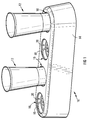
- a first embodiment of a liquid dispensing system in accordance with the invention, includes a dispensing apparatus designated generally by the reference numeral 10 and containers designated generally by the reference numeral 12, the containers being configured as described hereafter in order to permit dispensing of, for example, a carbonated beverage, beer, or the like, from a storage container via the dispensing apparatus 10 into a container 12.
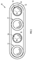
- the liquid dispensing apparatus 10 includes a base structure 14 which can be positioned on or mounted on a suitable support surface, the apparatus 10 being configured particularly to permit dispensing of liquid simultaneously into four containers. It must be understood in this regard that different dispensing apparatus can be provided which will permit dispensing of liquid simultaneously into any alternative number of containers, as may be required for different practical applications.
- the base structure 14 accordingly defines four receiving and locating formations 16 that are configured to receive and locate the bottom end of a container 12 therein, each formation 16 being associated with a nozzle 18 whereby a liquid can be dispensed into a container, the mode of support of a container and actual dispensing of a liquid into a container being described in more detail hereafter.
- All the nozzles 18 are connected in liquid communication with a liquid storage container (not shown), i.e. a storage container containing the liquid to be dispensed, the storage container typically being located at a remote location from the dispensing apparatus 10.
- a liquid storage container i.e. a storage container containing the liquid to be dispensed
- the storage container typically being located at a remote location from the dispensing apparatus 10.
- the liquid contained in a storage container may be under pressure or, alternatively, the storage container may be located at an elevated level above the dispensing apparatus in order to provide for a gravity feed of liquid therefrom.
- the dispensing apparatus may include a suitable liquid displacement means, e.g. a pump, which is operable to displace liquid from a liquid storage container into a container 12 via a nozzle 18 of the dispensing apparatus.
- the dispensing apparatus 10 further includes control means (not shown) for controlling dispensing of a liquid into a container, the control means typically being electronically operable and controlling the flow of liquid through each particular nozzle through which a liquid should be dispensed into a container and also the volume of liquid to be dispensed into a container.
- control means typically being electronically operable and controlling the flow of liquid through each particular nozzle through which a liquid should be dispensed into a container and also the volume of liquid to be dispensed into a container.
- Many different configuration control means are envisaged and may be associated with different configuration dispensing apparatus and, once again, this is not described in further detail herein.
- each receiving and locating formation 16 comprises a recess formation having diametrically opposite locating pins 20 projecting towards one another as shown, the pins 20 being configured to cooperate with formations 22 defined within the base region of a container, operatively beneath the base wall of the container, for locating the container within a formation 16.
- the pins 20 and the formations 22, as shown, are configured to cooperate in a bayonet-type fashion to provide for the required location of a container 12 in a formation 16 in order to permit dispensing of a liquid into the container.
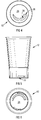
- each container 12 has a charging opening defined by a passage formation 26 that leads into the interior of the container above the base wall 24 from an opening 28 defined within the base wall 24, the passage formation having a one-way valve 30 (not clearly illustrated) located therein.
- the one-way valve 30 is a known type silicone flap-type valve that permits the insertion of a nozzle 18 into the passage formation beyond the valve and, as such, dispensing of a liquid into a container 12 via the nozzle, when so located.
- the location of a nozzle 18 into a passage formation 26 will occur as part of the locating process of a container 12 within a formation 16, which involves also the engagement of the pins 20 and formations 22 as described.
- the reverse operation will be effected after a container has been filled with a liquid, to permit removal of a container from the dispensing apparatus.
- the one-way valve 30 Upon the withdrawal of a nozzle 18 from a passage formation 26, the one-way valve 30 will effectively block the passage formation, thus sealing the base wall of the container and ensuring the required retention of liquid within the container. While a nozzle 18 penetrates the one-way valve 30, it will form a seal around then nozzle.
- containers 12 are greatly variable while still incorporating the use of apparatus and containers including the essential principles of the invention as hereinabove described and which provides for "bottom filling" of containers as opposed to conventional "top filling” of containers via nozzles located above the open top ends of containers.
- the apparatus can include an integrated dispensing unit which incorporates a dispensing nozzle, a receiving and location formation for a container, control means for controlling the volume of liquid dispensed into a container, which typically includes a flow meter, and a connector arrangement for connecting the dispensing nozzle thereof to a liquid supply line.
- a dispensing unit can then be associated with any suitable base structure or means for its support in a configuration in which it can be used for dispensing a liquid.
- a plurality of dispensing units as envisaged can be mounted into a base structure which can be supported on a support surface, so that with all the connector arrangements of the units connected to a liquid supply line, a liquid dispensing apparatus is provided which is essentially the equivalent of the apparatus 10.
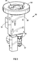
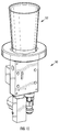
- a dispensing unit as above envisaged as part of a liquid dispensing apparatus is designated generally by the reference numeral 50, whereas a container for use with the unit is designated generally by the reference numeral 52.
- the dispensing unit 50 includes a locating ring 54, an on/off valve assembly 56, control circuitry carried within a housing 58, an electronic flow meter 60 and a connector arrangement 62, all the above parts being integrated with one another in the configuration illustrated for forming the unit 50.
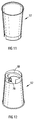
- the locating ring 54 defines a receiving and locating formation 64 within which the base region of the container 52 is receivable as shown in Figure 10 , particularly in a configuration in which a dispensing nozzle (not shown but being essentially the equivalent of the nozzle 18 of the dispensing apparatus 10 as above described) can penetrate into the interior of the container 52 via a charging opening and a one-way valve, as is already herein envisaged.
- the receiving and locating formation 64 defines guide formations therein, designated generally by the numeral 66, which are configured to cooperate with complementary formations, designated generally by the numeral 68, in the base region of the container 52 for guiding the displacement of the dispensing nozzle with respect to the container, particularly through rotation of the container while bearing downwardly thereon, which will provide for the dispensing nozzle to enter a passage 70 and pass through the passage into the container via a one-way valve 72 (not shown in detail). It will thus be understood that with the connector arrangement connected to a liquid supply line, through the operation of the control circuitry, a liquid will be dispensed into the container 52, particularly a predetermined controlled volume of this liquid which will provide for the liquid container to be effectively filled thereby.
- the container 52 clearly is configured specifically to cooperate with the dispensing unit 50, particularly in relation to its location within the receiving and locating formation 64, which provides for the dispensing nozzle of the unit to penetrate into the container to permit filling thereof.
- the dispensing nozzle will withdraw from the container while the flap valve will be acted upon by the liquid contained in the container for blocking the charging opening leading into the container, thus ensuring that liquid cannot leak from the container.
- the overall construction of the container 52 is thus essentially equivalent to that of the container 12 described above, except insofar as its base region is specifically configured to cooperate with the dispensing unit 50. This is thus not described in any further detail herein.
- dispensing units can be conveniently mounted into any suitable base structure in a configuration in which the locating rings thereof are disposed to facilitate the base region of containers to be received and located therein, it being envisaged that base structures can be configured to accommodate various different numbers of dispensing units, as will be determined by dispensing requirements.
- a liquid dispensing apparatus is provided which is essentially the equivalent of the apparatus 10 as above described.
- the exact configuration of the dispensing unit 50 and any base structure associated therewith can be varied in many different respects, while the mode of cooperation between the unit and containers to be used therewith also can be varied.
Claims (6)
- Système de distribution de liquide, qui inclut un appareil de distribution du liquide (10, 50) incluant un agencement de liaison pour relier une buse de distribution à un récipient de fourniture de liquide, et des récipients (12, 52) configurés pour une utilisation avec l'appareil (10, 50),
l'appareil de distribution de liquide (10, 50) ayant une structure de base qui définit au moins une structure de réception et de positionnement (16, 64) à l'intérieur de laquelle la buse de distribution (18) est située, et
chaque récipient (12, 52) incluant, dans sa zone de base, une ouverture de chargement (28, 70) et un clapet antiretour (30, 72) situé dans l'ouverture de chargement (28, 70) pour la distribution d'un liquide dans le récipient (12, 52),
la buse de distribution (18) étant située à l'intérieur de la structure de réception et de positionnement (16, 64) pour pénétrer dans le récipient (12, 52), qui est situé à l'intérieur de la structure de réception et de positionnement, par son ouverture de chargement (28, 70) et le clapet antiretour (30, 72),
la structure de réception et de positionnement (16, 64) définit des structures de guidage (20, 66) dans celle-ci, qui sont configurées pour coopérer avec des structures de guidage complémentaires (22, 68) dans la zone de base du récipient (12, 52) pour guider le déplacement de la buse de distribution (18) par rapport au récipient (12, 52) par rotation du récipient (12, 52) de telle sorte que la buse de distribution (18) pénètre dans l'ouverture de chargement (28, 70) et le clapet antiretour (30, 72) pour permettre une distribution du liquide dans le récipient (12, 52), et
le clapet antiretour (30, 72) étant configuré pour former un joint autour de la buse de distribution (18) lorsque la buse de distribution (18) pénètre dans le clapet antiretour (30, 72) et pour étanchéifier l'ouverture de chargement (28, 70) lorsque la buse de distribution (18) est rétractée à partir de l'ouverture de chargement (28, 70) en utilisation par contre-rotation du récipient (12, 52) par rapport à la buse de distribution (18). - Système de distribution de liquide selon la revendication 1, dans lequel l'appareil de distribution (10, 50) inclut des moyens de commande (56, 58, 60, 62) pour commander la distribution d'un liquide dans un récipient (12, 52).
- Système de distribution de liquide selon la revendication 2, dans lequel les moyens de commande (56, 58, 60, 62) permettent de distribuer un volume de liquide fixe dans un récipient (12, 52).
- Système de distribution de liquide selon l'une quelconque des revendications précédentes, dans lequel l'appareil de distribution de liquide (10, 50) inclut une structure de base qui définit une pluralité de structures de réception et de positionnement (16, 64).
- Appareil de distribution de liquide pour une utilisation dans un système de distribution de liquide selon l'une quelconque des revendications 1 à 4, incluant un agencement de raccordement pour raccorder une buse de distribution à un récipient de fourniture de liquide, l'appareil de distribution de liquide (10, 50) ayant une structure de base qui définit au moins une structure de réception et de positionnement (16, 64) à l'intérieur de laquelle la buse de distribution (18) est située pour pénétrer dans un récipient, la structure de réception et de positionnement (16, 64) définit des structures de guidage (20, 66) dans celle-ci, qui sont configurées pour coopérer avec des structures de guidage complémentaires (22, 68) dans la zone de base du récipient (12, 52) pour guider le déplacement de la buse de distribution (18) par rapport au récipient (12, 52) par rotation du récipient (12, 52) de telle sorte que la buse de distribution (18) pénètre dans une ouverture de chargement (28, 70) et un clapet antiretour (30, 72) du récipient pour permettre la distribution du liquide dans le récipient (12, 52).
- Récipient pour une utilisation dans un système de distribution de liquide selon l'une quelconque des revendications 1 à 4, le récipient (12, 52) incluant, dans sa zone de base, une ouverture de chargement (28, 70), un clapet antiretour (30, 72) situé dans l'ouverture de chargement (28, 70) pour distribuer un liquide dans le récipient (12, 52), et des structures de guidage complémentaires (22, 68) configurées pour coopérer avec des structures de guidage (20, 66) définies par la structure de réception et de positionnement (16, 64) de l'appareil de distribution de liquide pour guider le déplacement de la buse de distribution (18) par rapport au récipient (12, 52) par rotation du récipient (12, 52) de telle sorte que la buse de distribution (18) pénètre dans l'ouverture de chargement (28, 70) et le clapet antiretour (30, 72) pour permettre la distribution du liquide dans le récipient (12, 52), et le clapet antiretour (30, 72) étant configuré pour former un joint autour de la buse de distribution (18) lorsque la buse de distribution (18) pénètre dans le clapet antiretour (30, 72) et pour étanchéifier l'ouverture de chargement (28, 70) lorsque la buse de distribution (18) est rétractée à partir de l'ouverture de chargement (28, 70) en utilisation par contre-rotation du récipient (12, 52) par rapport à la buse de distribution (18).
Applications Claiming Priority (2)
| Application Number | Priority Date | Filing Date | Title |
|---|---|---|---|
| ZA200604626 | 2006-06-06 | ||
| PCT/IB2007/052066 WO2007141719A1 (fr) | 2006-06-06 | 2007-06-01 | Système de distribution de liquide |
Publications (2)
| Publication Number | Publication Date |
|---|---|
| EP2029470A1 EP2029470A1 (fr) | 2009-03-04 |
| EP2029470B1 true EP2029470B1 (fr) | 2016-08-17 |
Family
ID=38596827
Family Applications (1)
| Application Number | Title | Priority Date | Filing Date |
|---|---|---|---|
| EP07736066.7A Not-in-force EP2029470B1 (fr) | 2006-06-06 | 2007-06-01 | Système de distribution de liquide |
Country Status (5)
| Country | Link |
|---|---|
| US (1) | US8151838B2 (fr) |
| EP (1) | EP2029470B1 (fr) |
| AU (1) | AU2007257569B2 (fr) |
| WO (1) | WO2007141719A1 (fr) |
| ZA (1) | ZA200810795B (fr) |
Cited By (3)
| Publication number | Priority date | Publication date | Assignee | Title |
|---|---|---|---|---|
| WO2019078748A1 (fr) | 2017-10-20 | 2019-04-25 | Novadelta - Comércio E Indústria De Cafés, Lda | Système de préparation de boissons avec retenue associée à la forme de récipients pour boissons |
| US11325820B2 (en) | 2018-08-01 | 2022-05-10 | Novadelta-Comércio E Indéstria De Cafés, Lda | Beverage distribution system with composed drinking recipients, and process of operation thereof |
| US11524884B2 (en) | 2018-08-01 | 2022-12-13 | Novadelta—Comércio E Indústria De Cafés, Lda | Beverage distribution system with ergonomic retention of drinking recipients, and process of operation thereof |
Families Citing this family (26)
| Publication number | Priority date | Publication date | Assignee | Title |
|---|---|---|---|---|
| US8777182B2 (en) | 2008-05-20 | 2014-07-15 | Grinon Industries | Fluid transfer assembly and methods of fluid transfer |
| WO2009143164A1 (fr) * | 2008-05-20 | 2009-11-26 | Grinon Industries | Ensemble transfert de fluide et procédés de transfert de fluide |
| JP5890326B2 (ja) * | 2010-02-26 | 2016-03-22 | マニトワック・フードサービス・カンパニーズ・エルエルシー | 分注システム及び分注システムを制御する方法 |
| DE102011052032A1 (de) * | 2011-07-21 | 2013-01-24 | Inuma Fahrzeug-Service Und Maschinenbau Gmbh | Adapterelement für eine Düseneinheit zum Ausströmen einer Flüssigkeit und Vorrichtung zum Ausströmen einer Flüssigkeit |
| CA2862646C (fr) | 2011-12-30 | 2020-06-02 | Grinon Industries | Ensemble de transfert de fluide et methodes de transfert de fluide |
| US9016333B2 (en) * | 2013-01-02 | 2015-04-28 | General Electric Company | Bottom fill kitchen sink feature |
| JP6105343B2 (ja) * | 2013-03-19 | 2017-03-29 | 有限会社ユタカ産業 | 飲料コップ本体 |
| JP5650779B2 (ja) * | 2013-03-26 | 2015-01-07 | 有限会社ユタカ産業 | 逆止弁付栓 |
| KR101656422B1 (ko) * | 2014-06-17 | 2016-09-12 | (주)제이알피코퍼레이션 | 바닥을 통해 음료 주입이 이루어지는 음료 용기 |
| CN104310292A (zh) * | 2014-10-11 | 2015-01-28 | 北京维佳创机电控制技术有限公司 | 一种啤酒出酒装置 |
| CH710343A1 (fr) | 2014-11-07 | 2016-05-13 | Ip Évolution Sa | Gobelet permettant le remplissage par le dessous et dispositif de connexion pour le gobelet. |
| FR3035100B1 (fr) * | 2015-04-14 | 2021-01-29 | Olivier Bernard Sylvain Jammes | Dispositif de remplissage d'un contenant de boissons, notamment par son fond |
| KR101682616B1 (ko) * | 2015-05-12 | 2016-12-05 | 엔피씨(주) | 음료주입장치 |
| KR20160133129A (ko) * | 2015-05-12 | 2016-11-22 | 엔피씨(주) | 음료 용기 및 음료 주입 장치 어셈블리 |
| CN104840064B (zh) * | 2015-05-18 | 2017-05-03 | 王龙 | 一种底部注入式啤酒机 |
| US10759644B2 (en) * | 2015-05-21 | 2020-09-01 | Pepsico, Inc. | Digital table |
| DE202015106931U1 (de) * | 2015-12-18 | 2016-01-15 | Dirk Bolender | Behältnis zur Aufnahme von Getränken und Vorrichtung zur Befüllung des Behältnisses |
| JP6768332B2 (ja) * | 2016-04-08 | 2020-10-14 | 有限会社ユタカ産業 | 容器本体 |
| US9742889B1 (en) * | 2016-06-07 | 2017-08-22 | Cherokee Nation Entertainment, Llc | Lighted phone charger and cup holder device |
| CN106180102B (zh) * | 2016-07-14 | 2018-09-18 | 珠海优特物联科技有限公司 | 一种杯体及其驱动装置 |
| EP3281567A1 (fr) * | 2016-08-08 | 2018-02-14 | RIPRUP Company S.A. | Carafe intelligent |
| CA3092991A1 (fr) * | 2018-03-12 | 2019-09-19 | Grinon Industries | Systemes de distribution de boisson et procedes associes |
| KR102469581B1 (ko) * | 2018-08-30 | 2022-11-23 | 휴렛-팩커드 디벨롭먼트 컴퍼니, 엘.피. | 인쇄 물질 보충 |
| US11738986B2 (en) * | 2021-02-16 | 2023-08-29 | Aquaphant, Inc. | Refillable bottle |
| CN111743364A (zh) * | 2020-07-14 | 2020-10-09 | 上海电机学院 | 一种气压抽水式保温杯及其使用方法 |
| US11530868B2 (en) * | 2021-01-21 | 2022-12-20 | Haier Us Appliance Solutions, Inc. | Herb storage assembly for a refrigerator appliance |
Family Cites Families (6)
| Publication number | Priority date | Publication date | Assignee | Title |
|---|---|---|---|---|
| US3601164A (en) * | 1969-03-03 | 1971-08-24 | Sterigard Corp | Apparatus for injecting propellant into a dispensing container |
| DE8307900U1 (de) * | 1983-03-18 | 1984-07-19 | Wella Ag, 6100 Darmstadt | Selbstschliessendes Bodenventil eines Aufnahmebehaelters fuer pastoese oder fluessige Stoffe |
| GB2137171A (en) | 1983-03-23 | 1984-10-03 | Growers Requisites Northern Li | Collapsible boxes or trays |
| US20040256401A1 (en) | 2003-06-19 | 2004-12-23 | Chodosh David Jeffrey | Beverage container attachment |
| US6883564B2 (en) * | 2003-07-22 | 2005-04-26 | Thomas M. Risch | Pressurizing system for a dispensing container |
| IES20060165A2 (en) | 2006-03-06 | 2007-05-16 | Charles Russell | Drinking vessel and method and apparatus for dispensing a beverage |
-
2007
- 2007-06-01 AU AU2007257569A patent/AU2007257569B2/en not_active Ceased
- 2007-06-01 US US12/303,739 patent/US8151838B2/en not_active Expired - Fee Related
- 2007-06-01 WO PCT/IB2007/052066 patent/WO2007141719A1/fr active Application Filing
- 2007-06-01 EP EP07736066.7A patent/EP2029470B1/fr not_active Not-in-force
-
2008
- 2008-12-22 ZA ZA2008/10795A patent/ZA200810795B/en unknown
Non-Patent Citations (1)
| Title |
|---|
| None * |
Cited By (3)
| Publication number | Priority date | Publication date | Assignee | Title |
|---|---|---|---|---|
| WO2019078748A1 (fr) | 2017-10-20 | 2019-04-25 | Novadelta - Comércio E Indústria De Cafés, Lda | Système de préparation de boissons avec retenue associée à la forme de récipients pour boissons |
| US11325820B2 (en) | 2018-08-01 | 2022-05-10 | Novadelta-Comércio E Indéstria De Cafés, Lda | Beverage distribution system with composed drinking recipients, and process of operation thereof |
| US11524884B2 (en) | 2018-08-01 | 2022-12-13 | Novadelta—Comércio E Indústria De Cafés, Lda | Beverage distribution system with ergonomic retention of drinking recipients, and process of operation thereof |
Also Published As
| Publication number | Publication date |
|---|---|
| AU2007257569B2 (en) | 2012-02-02 |
| ZA200810795B (en) | 2012-02-29 |
| WO2007141719A1 (fr) | 2007-12-13 |
| US20100230007A1 (en) | 2010-09-16 |
| US8151838B2 (en) | 2012-04-10 |
| AU2007257569A1 (en) | 2007-12-13 |
| EP2029470A1 (fr) | 2009-03-04 |
Similar Documents
| Publication | Publication Date | Title |
|---|---|---|
| EP2029470B1 (fr) | Système de distribution de liquide | |
| JP2019116322A (ja) | カートリッジホルダを有するディスペンサ、これを用いたシステムおよび方法 | |
| KR101545349B1 (ko) | 음료 기계 및 음료 기계의 개방 장치용 천공 부재 | |
| US20170311750A1 (en) | Beverage producing system and capsule | |
| CN100376815C (zh) | 润滑液体注入设备 | |
| CN102015471A (zh) | 一种用于新鲜热饮料的自动料盒输送机和冲泡机组件 | |
| RU2615626C2 (ru) | Устройство дозирования, снабженное устройством для размещения резервуара | |
| EP0102527A2 (fr) | Distributeur de boissons | |
| US10875757B2 (en) | Beverage extractor for sparkling beverages | |
| CN105263375A (zh) | 胶囊机器和部件 | |
| WO2007042486A3 (fr) | Cartouche, dispositif et procede pour la preparation d'une boisson infusee | |
| JP2009528956A (ja) | 底部から注ぐことができる飲用容器及びそれに飲料を分配する装置 | |
| EP2888183B1 (fr) | Capsule à utiliser dans une machine de préparation d'aliments | |
| CN104244777A (zh) | 用于饮料制备机器的胶囊保持器 | |
| KR20190019166A (ko) | 음료 추출기에 사용하는 음료 용기 캡 | |
| JP2015536166A (ja) | カプセルで飲料を調製するための装置および方法 | |
| US20190152756A1 (en) | Vessel extraction apparatus and vessel therefore | |
| EP3199071B1 (fr) | Système pour préparer une boisson liquide à partir d'une capsule | |
| EP3297947B1 (fr) | Appareil de stockage et de distribution de liquide depuis un sac de retenue de liquide | |
| US20230337850A1 (en) | Beverage preparation machine and method for preparing a beverage with such a beverage preparation machine | |
| EP3659945A1 (fr) | Capsule avec insert d'injecteur | |
| US9451848B2 (en) | Beverage dispenser and coffee maker | |
| WO2008072240A2 (fr) | Dispositif pour maintenir le co2 dans une bouteille contenant une boisson gazeuse | |
| EP3199072A1 (fr) | Système pour préparer une boisson liquide à partir d'une capsule, capsule conçue pour être utilisée dans un système |
Legal Events
| Date | Code | Title | Description |
|---|---|---|---|
| PUAI | Public reference made under article 153(3) epc to a published international application that has entered the european phase |
Free format text: ORIGINAL CODE: 0009012 |
|
| 17P | Request for examination filed |
Effective date: 20090105 |
|
| AK | Designated contracting states |
Kind code of ref document: A1 Designated state(s): AT BE BG CH CY CZ DE DK EE ES FI FR GB GR HU IE IS IT LI LT LU LV MC MT NL PL PT RO SE SI SK TR |
|
| AX | Request for extension of the european patent |
Extension state: AL BA HR MK RS |
|
| DAX | Request for extension of the european patent (deleted) | ||
| 17Q | First examination report despatched |
Effective date: 20130131 |
|
| GRAP | Despatch of communication of intention to grant a patent |
Free format text: ORIGINAL CODE: EPIDOSNIGR1 |
|
| INTG | Intention to grant announced |
Effective date: 20160217 |
|
| GRAR | Information related to intention to grant a patent recorded |
Free format text: ORIGINAL CODE: EPIDOSNIGR71 |
|
| GRAS | Grant fee paid |
Free format text: ORIGINAL CODE: EPIDOSNIGR3 |
|
| GRAA | (expected) grant |
Free format text: ORIGINAL CODE: 0009210 |
|
| AK | Designated contracting states |
Kind code of ref document: B1 Designated state(s): AT BE BG CH CY CZ DE DK EE ES FI FR GB GR HU IE IS IT LI LT LU LV MC MT NL PL PT RO SE SI SK TR |
|
| INTG | Intention to grant announced |
Effective date: 20160711 |
|
| REG | Reference to a national code |
Ref country code: GB Ref legal event code: FG4D |
|
| REG | Reference to a national code |
Ref country code: CH Ref legal event code: EP |
|
| REG | Reference to a national code |
Ref country code: IE Ref legal event code: FG4D |
|
| REG | Reference to a national code |
Ref country code: AT Ref legal event code: REF Ref document number: 820866 Country of ref document: AT Kind code of ref document: T Effective date: 20160915 |
|
| REG | Reference to a national code |
Ref country code: DE Ref legal event code: R096 Ref document number: 602007047500 Country of ref document: DE |
|
| REG | Reference to a national code |
Ref country code: NL Ref legal event code: FP |
|
| REG | Reference to a national code |
Ref country code: LT Ref legal event code: MG4D |
|
| REG | Reference to a national code |
Ref country code: AT Ref legal event code: MK05 Ref document number: 820866 Country of ref document: AT Kind code of ref document: T Effective date: 20160817 |
|
| PG25 | Lapsed in a contracting state [announced via postgrant information from national office to epo] |
Ref country code: LT Free format text: LAPSE BECAUSE OF FAILURE TO SUBMIT A TRANSLATION OF THE DESCRIPTION OR TO PAY THE FEE WITHIN THE PRESCRIBED TIME-LIMIT Effective date: 20160817 Ref country code: FI Free format text: LAPSE BECAUSE OF FAILURE TO SUBMIT A TRANSLATION OF THE DESCRIPTION OR TO PAY THE FEE WITHIN THE PRESCRIBED TIME-LIMIT Effective date: 20160817 Ref country code: IT Free format text: LAPSE BECAUSE OF FAILURE TO SUBMIT A TRANSLATION OF THE DESCRIPTION OR TO PAY THE FEE WITHIN THE PRESCRIBED TIME-LIMIT Effective date: 20160817 |
|
| PG25 | Lapsed in a contracting state [announced via postgrant information from national office to epo] |
Ref country code: AT Free format text: LAPSE BECAUSE OF FAILURE TO SUBMIT A TRANSLATION OF THE DESCRIPTION OR TO PAY THE FEE WITHIN THE PRESCRIBED TIME-LIMIT Effective date: 20160817 Ref country code: SE Free format text: LAPSE BECAUSE OF FAILURE TO SUBMIT A TRANSLATION OF THE DESCRIPTION OR TO PAY THE FEE WITHIN THE PRESCRIBED TIME-LIMIT Effective date: 20160817 Ref country code: ES Free format text: LAPSE BECAUSE OF FAILURE TO SUBMIT A TRANSLATION OF THE DESCRIPTION OR TO PAY THE FEE WITHIN THE PRESCRIBED TIME-LIMIT Effective date: 20160817 Ref country code: GR Free format text: LAPSE BECAUSE OF FAILURE TO SUBMIT A TRANSLATION OF THE DESCRIPTION OR TO PAY THE FEE WITHIN THE PRESCRIBED TIME-LIMIT Effective date: 20161118 Ref country code: LV Free format text: LAPSE BECAUSE OF FAILURE TO SUBMIT A TRANSLATION OF THE DESCRIPTION OR TO PAY THE FEE WITHIN THE PRESCRIBED TIME-LIMIT Effective date: 20160817 Ref country code: PL Free format text: LAPSE BECAUSE OF FAILURE TO SUBMIT A TRANSLATION OF THE DESCRIPTION OR TO PAY THE FEE WITHIN THE PRESCRIBED TIME-LIMIT Effective date: 20160817 Ref country code: PT Free format text: LAPSE BECAUSE OF FAILURE TO SUBMIT A TRANSLATION OF THE DESCRIPTION OR TO PAY THE FEE WITHIN THE PRESCRIBED TIME-LIMIT Effective date: 20161219 |
|
| PG25 | Lapsed in a contracting state [announced via postgrant information from national office to epo] |
Ref country code: EE Free format text: LAPSE BECAUSE OF FAILURE TO SUBMIT A TRANSLATION OF THE DESCRIPTION OR TO PAY THE FEE WITHIN THE PRESCRIBED TIME-LIMIT Effective date: 20160817 Ref country code: RO Free format text: LAPSE BECAUSE OF FAILURE TO SUBMIT A TRANSLATION OF THE DESCRIPTION OR TO PAY THE FEE WITHIN THE PRESCRIBED TIME-LIMIT Effective date: 20160817 |
|
| REG | Reference to a national code |
Ref country code: DE Ref legal event code: R097 Ref document number: 602007047500 Country of ref document: DE |
|
| PG25 | Lapsed in a contracting state [announced via postgrant information from national office to epo] |
Ref country code: CZ Free format text: LAPSE BECAUSE OF FAILURE TO SUBMIT A TRANSLATION OF THE DESCRIPTION OR TO PAY THE FEE WITHIN THE PRESCRIBED TIME-LIMIT Effective date: 20160817 Ref country code: DK Free format text: LAPSE BECAUSE OF FAILURE TO SUBMIT A TRANSLATION OF THE DESCRIPTION OR TO PAY THE FEE WITHIN THE PRESCRIBED TIME-LIMIT Effective date: 20160817 Ref country code: BG Free format text: LAPSE BECAUSE OF FAILURE TO SUBMIT A TRANSLATION OF THE DESCRIPTION OR TO PAY THE FEE WITHIN THE PRESCRIBED TIME-LIMIT Effective date: 20161117 Ref country code: SK Free format text: LAPSE BECAUSE OF FAILURE TO SUBMIT A TRANSLATION OF THE DESCRIPTION OR TO PAY THE FEE WITHIN THE PRESCRIBED TIME-LIMIT Effective date: 20160817 Ref country code: BE Free format text: LAPSE BECAUSE OF FAILURE TO SUBMIT A TRANSLATION OF THE DESCRIPTION OR TO PAY THE FEE WITHIN THE PRESCRIBED TIME-LIMIT Effective date: 20160817 |
|
| REG | Reference to a national code |
Ref country code: FR Ref legal event code: PLFP Year of fee payment: 11 |
|
| PLBE | No opposition filed within time limit |
Free format text: ORIGINAL CODE: 0009261 |
|
| STAA | Information on the status of an ep patent application or granted ep patent |
Free format text: STATUS: NO OPPOSITION FILED WITHIN TIME LIMIT |
|
| 26N | No opposition filed |
Effective date: 20170518 |
|
| PG25 | Lapsed in a contracting state [announced via postgrant information from national office to epo] |
Ref country code: SI Free format text: LAPSE BECAUSE OF FAILURE TO SUBMIT A TRANSLATION OF THE DESCRIPTION OR TO PAY THE FEE WITHIN THE PRESCRIBED TIME-LIMIT Effective date: 20160817 |
|
| PG25 | Lapsed in a contracting state [announced via postgrant information from national office to epo] |
Ref country code: MC Free format text: LAPSE BECAUSE OF FAILURE TO SUBMIT A TRANSLATION OF THE DESCRIPTION OR TO PAY THE FEE WITHIN THE PRESCRIBED TIME-LIMIT Effective date: 20160817 |
|
| REG | Reference to a national code |
Ref country code: CH Ref legal event code: PL |
|
| REG | Reference to a national code |
Ref country code: IE Ref legal event code: MM4A |
|
| PG25 | Lapsed in a contracting state [announced via postgrant information from national office to epo] |
Ref country code: LI Free format text: LAPSE BECAUSE OF NON-PAYMENT OF DUE FEES Effective date: 20170630 Ref country code: CH Free format text: LAPSE BECAUSE OF NON-PAYMENT OF DUE FEES Effective date: 20170630 Ref country code: IE Free format text: LAPSE BECAUSE OF NON-PAYMENT OF DUE FEES Effective date: 20170601 Ref country code: LU Free format text: LAPSE BECAUSE OF NON-PAYMENT OF DUE FEES Effective date: 20170601 |
|
| REG | Reference to a national code |
Ref country code: FR Ref legal event code: PLFP Year of fee payment: 12 |
|
| PGFP | Annual fee paid to national office [announced via postgrant information from national office to epo] |
Ref country code: FR Payment date: 20180627 Year of fee payment: 12 |
|
| PG25 | Lapsed in a contracting state [announced via postgrant information from national office to epo] |
Ref country code: MT Free format text: LAPSE BECAUSE OF NON-PAYMENT OF DUE FEES Effective date: 20170601 |
|
| PGFP | Annual fee paid to national office [announced via postgrant information from national office to epo] |
Ref country code: ES Payment date: 20180702 Year of fee payment: 12 Ref country code: DE Payment date: 20180702 Year of fee payment: 12 |
|
| PG25 | Lapsed in a contracting state [announced via postgrant information from national office to epo] |
Ref country code: HU Free format text: LAPSE BECAUSE OF FAILURE TO SUBMIT A TRANSLATION OF THE DESCRIPTION OR TO PAY THE FEE WITHIN THE PRESCRIBED TIME-LIMIT; INVALID AB INITIO Effective date: 20070601 |
|
| PG25 | Lapsed in a contracting state [announced via postgrant information from national office to epo] |
Ref country code: CY Free format text: LAPSE BECAUSE OF NON-PAYMENT OF DUE FEES Effective date: 20160817 |
|
| REG | Reference to a national code |
Ref country code: DE Ref legal event code: R119 Ref document number: 602007047500 Country of ref document: DE |
|
| REG | Reference to a national code |
Ref country code: NL Ref legal event code: MM Effective date: 20190701 |
|
| PG25 | Lapsed in a contracting state [announced via postgrant information from national office to epo] |
Ref country code: TR Free format text: LAPSE BECAUSE OF FAILURE TO SUBMIT A TRANSLATION OF THE DESCRIPTION OR TO PAY THE FEE WITHIN THE PRESCRIBED TIME-LIMIT Effective date: 20160817 |
|
| PG25 | Lapsed in a contracting state [announced via postgrant information from national office to epo] |
Ref country code: DE Free format text: LAPSE BECAUSE OF NON-PAYMENT OF DUE FEES Effective date: 20200101 Ref country code: NL Free format text: LAPSE BECAUSE OF NON-PAYMENT OF DUE FEES Effective date: 20190701 |
|
| PG25 | Lapsed in a contracting state [announced via postgrant information from national office to epo] |
Ref country code: FR Free format text: LAPSE BECAUSE OF NON-PAYMENT OF DUE FEES Effective date: 20190630 |
|
| PG25 | Lapsed in a contracting state [announced via postgrant information from national office to epo] |
Ref country code: IS Free format text: LAPSE BECAUSE OF FAILURE TO SUBMIT A TRANSLATION OF THE DESCRIPTION OR TO PAY THE FEE WITHIN THE PRESCRIBED TIME-LIMIT Effective date: 20161217 |
|
| PGFP | Annual fee paid to national office [announced via postgrant information from national office to epo] |
Ref country code: GB Payment date: 20220627 Year of fee payment: 16 |
|
| GBPC | Gb: european patent ceased through non-payment of renewal fee |
Effective date: 20230601 |
|
| PG25 | Lapsed in a contracting state [announced via postgrant information from national office to epo] |
Ref country code: GB Free format text: LAPSE BECAUSE OF NON-PAYMENT OF DUE FEES Effective date: 20230601 |