EP2029470B1 - A liquid dispensing system - Google Patents
A liquid dispensing system Download PDFInfo
- Publication number
- EP2029470B1 EP2029470B1 EP07736066.7A EP07736066A EP2029470B1 EP 2029470 B1 EP2029470 B1 EP 2029470B1 EP 07736066 A EP07736066 A EP 07736066A EP 2029470 B1 EP2029470 B1 EP 2029470B1
- Authority
- EP
- European Patent Office
- Prior art keywords
- container
- liquid
- dispensing
- nozzle
- dispensing nozzle
- Prior art date
- Legal status (The legal status is an assumption and is not a legal conclusion. Google has not performed a legal analysis and makes no representation as to the accuracy of the status listed.)
- Not-in-force
Links
- 239000007788 liquid Substances 0.000 title claims description 112
- 230000015572 biosynthetic process Effects 0.000 claims description 47
- 238000005755 formation reaction Methods 0.000 claims description 47
- 238000006073 displacement reaction Methods 0.000 claims description 8
- 230000000295 complement effect Effects 0.000 claims description 5
- 230000000149 penetrating effect Effects 0.000 claims description 3
- 235000013405 beer Nutrition 0.000 description 3
- 235000014171 carbonated beverage Nutrition 0.000 description 3
- 239000000463 material Substances 0.000 description 3
- 238000010276 construction Methods 0.000 description 2
- 230000005484 gravity Effects 0.000 description 2
- 229920001296 polysiloxane Polymers 0.000 description 2
- 238000007789 sealing Methods 0.000 description 2
- 239000004743 Polypropylene Substances 0.000 description 1
- 230000000903 blocking effect Effects 0.000 description 1
- 238000004891 communication Methods 0.000 description 1
- 239000006260 foam Substances 0.000 description 1
- 238000003780 insertion Methods 0.000 description 1
- 230000037431 insertion Effects 0.000 description 1
- 230000014759 maintenance of location Effects 0.000 description 1
- 238000000034 method Methods 0.000 description 1
- 230000035515 penetration Effects 0.000 description 1
- 239000004033 plastic Substances 0.000 description 1
- 229920003023 plastic Polymers 0.000 description 1
- -1 polypropylene Polymers 0.000 description 1
- 229920001155 polypropylene Polymers 0.000 description 1
Images


Classifications
-
- B—PERFORMING OPERATIONS; TRANSPORTING
- B67—OPENING, CLOSING OR CLEANING BOTTLES, JARS OR SIMILAR CONTAINERS; LIQUID HANDLING
- B67D—DISPENSING, DELIVERING OR TRANSFERRING LIQUIDS, NOT OTHERWISE PROVIDED FOR
- B67D1/00—Apparatus or devices for dispensing beverages on draught
- B67D1/0003—Apparatus or devices for dispensing beverages on draught the beverage being a single liquid
- B67D1/0004—Apparatus or devices for dispensing beverages on draught the beverage being a single liquid the beverage being stored in a container, e.g. bottle, cartridge, bag-in-box, bowl
- B67D1/0005—Apparatus or devices for dispensing beverages on draught the beverage being a single liquid the beverage being stored in a container, e.g. bottle, cartridge, bag-in-box, bowl the apparatus comprising means for automatically controlling the amount to be dispensed
-
- A—HUMAN NECESSITIES
- A47—FURNITURE; DOMESTIC ARTICLES OR APPLIANCES; COFFEE MILLS; SPICE MILLS; SUCTION CLEANERS IN GENERAL
- A47G—HOUSEHOLD OR TABLE EQUIPMENT
- A47G19/00—Table service
- A47G19/22—Drinking vessels or saucers used for table service
- A47G19/2205—Drinking glasses or vessels
-
- B—PERFORMING OPERATIONS; TRANSPORTING
- B65—CONVEYING; PACKING; STORING; HANDLING THIN OR FILAMENTARY MATERIAL
- B65D—CONTAINERS FOR STORAGE OR TRANSPORT OF ARTICLES OR MATERIALS, e.g. BAGS, BARRELS, BOTTLES, BOXES, CANS, CARTONS, CRATES, DRUMS, JARS, TANKS, HOPPERS, FORWARDING CONTAINERS; ACCESSORIES, CLOSURES, OR FITTINGS THEREFOR; PACKAGING ELEMENTS; PACKAGES
- B65D1/00—Containers having bodies formed in one piece, e.g. by casting metallic material, by moulding plastics, by blowing vitreous material, by throwing ceramic material, by moulding pulped fibrous material, by deep-drawing operations performed on sheet material
- B65D1/02—Bottles or similar containers with necks or like restricted apertures, designed for pouring contents
- B65D1/06—Bottles or similar containers with necks or like restricted apertures, designed for pouring contents with closable apertures at bottom
-
- B—PERFORMING OPERATIONS; TRANSPORTING
- B67—OPENING, CLOSING OR CLEANING BOTTLES, JARS OR SIMILAR CONTAINERS; LIQUID HANDLING
- B67D—DISPENSING, DELIVERING OR TRANSFERRING LIQUIDS, NOT OTHERWISE PROVIDED FOR
- B67D1/00—Apparatus or devices for dispensing beverages on draught
- B67D1/06—Mountings or arrangements of dispensing apparatus in or on shop or bar counters
-
- B—PERFORMING OPERATIONS; TRANSPORTING
- B67—OPENING, CLOSING OR CLEANING BOTTLES, JARS OR SIMILAR CONTAINERS; LIQUID HANDLING
- B67D—DISPENSING, DELIVERING OR TRANSFERRING LIQUIDS, NOT OTHERWISE PROVIDED FOR
- B67D1/00—Apparatus or devices for dispensing beverages on draught
- B67D1/08—Details
- B67D1/12—Flow or pressure control devices or systems, e.g. valves, gas pressure control, level control in storage containers
- B67D1/1202—Flow control, e.g. for controlling total amount or mixture ratio of liquids to be dispensed
- B67D1/1234—Flow control, e.g. for controlling total amount or mixture ratio of liquids to be dispensed to determine the total amount
- B67D1/124—Flow control, e.g. for controlling total amount or mixture ratio of liquids to be dispensed to determine the total amount the flow being started or stopped by means actuated by the vessel to be filled, e.g. by switches, weighing
-
- B—PERFORMING OPERATIONS; TRANSPORTING
- B67—OPENING, CLOSING OR CLEANING BOTTLES, JARS OR SIMILAR CONTAINERS; LIQUID HANDLING
- B67D—DISPENSING, DELIVERING OR TRANSFERRING LIQUIDS, NOT OTHERWISE PROVIDED FOR
- B67D1/00—Apparatus or devices for dispensing beverages on draught
- B67D1/0042—Details of specific parts of the dispensers
- B67D1/0081—Dispensing valves
- B67D2001/0087—Dispensing valves being mounted on the dispenser housing
- B67D2001/009—Dispensing valves being mounted on the dispenser housing operated by cup detection
-
- B—PERFORMING OPERATIONS; TRANSPORTING
- B67—OPENING, CLOSING OR CLEANING BOTTLES, JARS OR SIMILAR CONTAINERS; LIQUID HANDLING
- B67D—DISPENSING, DELIVERING OR TRANSFERRING LIQUIDS, NOT OTHERWISE PROVIDED FOR
- B67D2210/00—Indexing scheme relating to aspects and details of apparatus or devices for dispensing beverages on draught or for controlling flow of liquids under gravity from storage containers for dispensing purposes
- B67D2210/00028—Constructional details
- B67D2210/00065—Constructional details related to the use of drinking cups or glasses
- B67D2210/00068—Means for filling simultaneously a plurality of cups
Definitions
- THIS INVENTION relates to a liquid dispensing system.
- the invention relates particularly to a liquid dispensing system that provides for dispensing of a liquid such as a carbonated beverage, beer, and the like, and that includes a liquid dispensing apparatus and containers for use with the apparatus and into which a liquid can be dispensed by the apparatus.
- GB 2137181 and WO 2007/102139 disclose liquid dispensing systems where a container includes a one-way valve in its base region and is configured to be inserted onto an upwardly facing dispensing nozzle of a liquid dispensing apparatus.
- a liquid dispensing system which includes a liquid dispensing apparatus and containers for use with the apparatus, the apparatus including at least one dispensing nozzle and each container including, in its base region, a charging opening and a one-way valve located in the opening and providing for dispensing of a liquid into the container by the penetration of the container by the dispensing nozzle of the apparatus via the charging opening and the one-way valve and sealing of the opening following retraction of the dispensing nozzle from the container.
- Each container as used within the dispensing system of the invention may be formed of a synthetic plastics material, typically a material such as polypropylene.
- the one-way valve of each container that is located in the charging opening thereof may be a flap-type valve, typically a flap-type valve of a silicone material.
- the one-way valve of each container forms a seal around the dispensing nozzle of the dispensing apparatus when the nozzle penetrates the container via its charging opening and the one-way valve.
- One-way valves suitable for the above purpose are already known.
- the liquid dispensing apparatus of the liquid dispensing system includes a connector arrangement for connecting the dispensing nozzle to a liquid supply container.
- the liquid dispensing apparatus may include liquid displacement means for displacing a liquid to be dispensed via the dispensing nozzle, the liquid displacement means typically being a pump.
- the liquid feed to the dispensing apparatus and particularly to the dispensing nozzle thereof may be a gravity feed arrangement or, still alternatively, may be a pressurized feed, i.e. a feed of liquid from a pressurized storage container.
- the liquid dispensing apparatus of the liquid dispensing system includes a base structure that defines at least one receiving and locating formation that has the dispensing nozzle located with respect thereto in a configuration in which a container can be positioned on the base structure within the receiving and locating formation with the dispensing nozzle penetrating the container via its charging opening and one-way valve.
- a base structure that defines at least one receiving and locating formation that has the dispensing nozzle located with respect thereto in a configuration in which a container can be positioned on the base structure within the receiving and locating formation with the dispensing nozzle penetrating the container via its charging opening and one-way valve.
- the liquid dispensing apparatus of the liquid dispensing system also may include a base structure that defines a plurality of receiving and locating formations that each has a dispensing nozzle located with respect thereto in a configuration in which containers can be positioned on the base structure within the receiving and locating formations with the dispensing nozzles penetrating these containers via their charging openings and one-way valves.
- Each receiving and locating formation defined by the base structure of the liquid dispensing apparatus and each container may define complementary guide formations that operatively cooperate with one another for guiding positioning of a container into a receiving and locating formation in a configuration in which the dispensing nozzle associated with the receiving and locating formation thereby penetrates the container via its charging opening and one-way valve.
- the dispensing apparatus may include control means for controlling the dispensing of a liquid into a container.
- the control means may provide for a fixed volume of liquid to be dispensed into the container or, alternatively, may include a sensing means that can sense the level of a liquid dispensed into a container and de-activate the apparatus to stop liquid being dispensed when a predetermined level of the liquid within the container is reached.
- control means may be configured either to control dispensing of liquid simultaneously into each container located within a receiving and locating formation, or to control dispensing of liquid into individual containers.
- the invention extends also to a liquid dispensing apparatus for use in a liquid dispensing system, in accordance with the invention, as well as to a container for use in a liquid dispensing system, in accordance with the invention.
- the invention provides also a container according to claim 6 and a liquid dispensing apparatus according to claim 5, that are provided for use in the system.
- a first embodiment of a liquid dispensing system in accordance with the invention, includes a dispensing apparatus designated generally by the reference numeral 10 and containers designated generally by the reference numeral 12, the containers being configured as described hereafter in order to permit dispensing of, for example, a carbonated beverage, beer, or the like, from a storage container via the dispensing apparatus 10 into a container 12.
- the liquid dispensing apparatus 10 includes a base structure 14 which can be positioned on or mounted on a suitable support surface, the apparatus 10 being configured particularly to permit dispensing of liquid simultaneously into four containers. It must be understood in this regard that different dispensing apparatus can be provided which will permit dispensing of liquid simultaneously into any alternative number of containers, as may be required for different practical applications.
- the base structure 14 accordingly defines four receiving and locating formations 16 that are configured to receive and locate the bottom end of a container 12 therein, each formation 16 being associated with a nozzle 18 whereby a liquid can be dispensed into a container, the mode of support of a container and actual dispensing of a liquid into a container being described in more detail hereafter.
- All the nozzles 18 are connected in liquid communication with a liquid storage container (not shown), i.e. a storage container containing the liquid to be dispensed, the storage container typically being located at a remote location from the dispensing apparatus 10.
- a liquid storage container i.e. a storage container containing the liquid to be dispensed
- the storage container typically being located at a remote location from the dispensing apparatus 10.
- the liquid contained in a storage container may be under pressure or, alternatively, the storage container may be located at an elevated level above the dispensing apparatus in order to provide for a gravity feed of liquid therefrom.
- the dispensing apparatus may include a suitable liquid displacement means, e.g. a pump, which is operable to displace liquid from a liquid storage container into a container 12 via a nozzle 18 of the dispensing apparatus.
- the dispensing apparatus 10 further includes control means (not shown) for controlling dispensing of a liquid into a container, the control means typically being electronically operable and controlling the flow of liquid through each particular nozzle through which a liquid should be dispensed into a container and also the volume of liquid to be dispensed into a container.
- control means typically being electronically operable and controlling the flow of liquid through each particular nozzle through which a liquid should be dispensed into a container and also the volume of liquid to be dispensed into a container.
- Many different configuration control means are envisaged and may be associated with different configuration dispensing apparatus and, once again, this is not described in further detail herein.
- each receiving and locating formation 16 comprises a recess formation having diametrically opposite locating pins 20 projecting towards one another as shown, the pins 20 being configured to cooperate with formations 22 defined within the base region of a container, operatively beneath the base wall of the container, for locating the container within a formation 16.
- the pins 20 and the formations 22, as shown, are configured to cooperate in a bayonet-type fashion to provide for the required location of a container 12 in a formation 16 in order to permit dispensing of a liquid into the container.
- each container 12 has a charging opening defined by a passage formation 26 that leads into the interior of the container above the base wall 24 from an opening 28 defined within the base wall 24, the passage formation having a one-way valve 30 (not clearly illustrated) located therein.
- the one-way valve 30 is a known type silicone flap-type valve that permits the insertion of a nozzle 18 into the passage formation beyond the valve and, as such, dispensing of a liquid into a container 12 via the nozzle, when so located.
- the location of a nozzle 18 into a passage formation 26 will occur as part of the locating process of a container 12 within a formation 16, which involves also the engagement of the pins 20 and formations 22 as described.
- the reverse operation will be effected after a container has been filled with a liquid, to permit removal of a container from the dispensing apparatus.
- the one-way valve 30 Upon the withdrawal of a nozzle 18 from a passage formation 26, the one-way valve 30 will effectively block the passage formation, thus sealing the base wall of the container and ensuring the required retention of liquid within the container. While a nozzle 18 penetrates the one-way valve 30, it will form a seal around then nozzle.
- containers 12 are greatly variable while still incorporating the use of apparatus and containers including the essential principles of the invention as hereinabove described and which provides for "bottom filling" of containers as opposed to conventional "top filling” of containers via nozzles located above the open top ends of containers.
- the apparatus can include an integrated dispensing unit which incorporates a dispensing nozzle, a receiving and location formation for a container, control means for controlling the volume of liquid dispensed into a container, which typically includes a flow meter, and a connector arrangement for connecting the dispensing nozzle thereof to a liquid supply line.
- a dispensing unit can then be associated with any suitable base structure or means for its support in a configuration in which it can be used for dispensing a liquid.
- a plurality of dispensing units as envisaged can be mounted into a base structure which can be supported on a support surface, so that with all the connector arrangements of the units connected to a liquid supply line, a liquid dispensing apparatus is provided which is essentially the equivalent of the apparatus 10.
- a dispensing unit as above envisaged as part of a liquid dispensing apparatus is designated generally by the reference numeral 50, whereas a container for use with the unit is designated generally by the reference numeral 52.
- the dispensing unit 50 includes a locating ring 54, an on/off valve assembly 56, control circuitry carried within a housing 58, an electronic flow meter 60 and a connector arrangement 62, all the above parts being integrated with one another in the configuration illustrated for forming the unit 50.
- the locating ring 54 defines a receiving and locating formation 64 within which the base region of the container 52 is receivable as shown in Figure 10 , particularly in a configuration in which a dispensing nozzle (not shown but being essentially the equivalent of the nozzle 18 of the dispensing apparatus 10 as above described) can penetrate into the interior of the container 52 via a charging opening and a one-way valve, as is already herein envisaged.
- the receiving and locating formation 64 defines guide formations therein, designated generally by the numeral 66, which are configured to cooperate with complementary formations, designated generally by the numeral 68, in the base region of the container 52 for guiding the displacement of the dispensing nozzle with respect to the container, particularly through rotation of the container while bearing downwardly thereon, which will provide for the dispensing nozzle to enter a passage 70 and pass through the passage into the container via a one-way valve 72 (not shown in detail). It will thus be understood that with the connector arrangement connected to a liquid supply line, through the operation of the control circuitry, a liquid will be dispensed into the container 52, particularly a predetermined controlled volume of this liquid which will provide for the liquid container to be effectively filled thereby.
- the container 52 clearly is configured specifically to cooperate with the dispensing unit 50, particularly in relation to its location within the receiving and locating formation 64, which provides for the dispensing nozzle of the unit to penetrate into the container to permit filling thereof.
- the dispensing nozzle will withdraw from the container while the flap valve will be acted upon by the liquid contained in the container for blocking the charging opening leading into the container, thus ensuring that liquid cannot leak from the container.
- the overall construction of the container 52 is thus essentially equivalent to that of the container 12 described above, except insofar as its base region is specifically configured to cooperate with the dispensing unit 50. This is thus not described in any further detail herein.
- dispensing units can be conveniently mounted into any suitable base structure in a configuration in which the locating rings thereof are disposed to facilitate the base region of containers to be received and located therein, it being envisaged that base structures can be configured to accommodate various different numbers of dispensing units, as will be determined by dispensing requirements.
- a liquid dispensing apparatus is provided which is essentially the equivalent of the apparatus 10 as above described.
- the exact configuration of the dispensing unit 50 and any base structure associated therewith can be varied in many different respects, while the mode of cooperation between the unit and containers to be used therewith also can be varied.
Description
- THIS INVENTION relates to a liquid dispensing system.
- The invention relates particularly to a liquid dispensing system that provides for dispensing of a liquid such as a carbonated beverage, beer, and the like, and that includes a liquid dispensing apparatus and containers for use with the apparatus and into which a liquid can be dispensed by the apparatus.
GB 2137181 WO 2007/102139 (Article 54(3) EPC document) disclose liquid dispensing systems where a container includes a one-way valve in its base region and is configured to be inserted onto an upwardly facing dispensing nozzle of a liquid dispensing apparatus. - According to the invention there is provided a liquid dispensing system according to
claim 1, which includes a liquid dispensing apparatus and containers for use with the apparatus, the apparatus including at least one dispensing nozzle and each container including, in its base region, a charging opening and a one-way valve located in the opening and providing for dispensing of a liquid into the container by the penetration of the container by the dispensing nozzle of the apparatus via the charging opening and the one-way valve and sealing of the opening following retraction of the dispensing nozzle from the container. - Each container as used within the dispensing system of the invention may be formed of a synthetic plastics material, typically a material such as polypropylene. The one-way valve of each container that is located in the charging opening thereof may be a flap-type valve, typically a flap-type valve of a silicone material. The one-way valve of each container forms a seal around the dispensing nozzle of the dispensing apparatus when the nozzle penetrates the container via its charging opening and the one-way valve. One-way valves suitable for the above purpose are already known.
- Further according to the invention, the liquid dispensing apparatus of the liquid dispensing system includes a connector arrangement for connecting the dispensing nozzle to a liquid supply container. As such, the liquid dispensing apparatus may include liquid displacement means for displacing a liquid to be dispensed via the dispensing nozzle, the liquid displacement means typically being a pump. The liquid feed to the dispensing apparatus and particularly to the dispensing nozzle thereof, alternatively, may be a gravity feed arrangement or, still alternatively, may be a pressurized feed, i.e. a feed of liquid from a pressurized storage container.
- The liquid dispensing apparatus of the liquid dispensing system includes a base structure that defines at least one receiving and locating formation that has the dispensing nozzle located with respect thereto in a configuration in which a container can be positioned on the base structure within the receiving and locating formation with the dispensing nozzle penetrating the container via its charging opening and one-way valve. Clearly, the configuration of the base structure and of the nozzle associated therewith is greatly variable, being determined particularly also by the configuration of the container into which a liquid can be dispensed via the system of the invention. The liquid dispensing apparatus of the liquid dispensing system also may include a base structure that defines a plurality of receiving and locating formations that each has a dispensing nozzle located with respect thereto in a configuration in which containers can be positioned on the base structure within the receiving and locating formations with the dispensing nozzles penetrating these containers via their charging openings and one-way valves. Each receiving and locating formation defined by the base structure of the liquid dispensing apparatus and each container may define complementary guide formations that operatively cooperate with one another for guiding positioning of a container into a receiving and locating formation in a configuration in which the dispensing nozzle associated with the receiving and locating formation thereby penetrates the container via its charging opening and one-way valve.
- Further according to the invention, the dispensing apparatus may include control means for controlling the dispensing of a liquid into a container. The control means may provide for a fixed volume of liquid to be dispensed into the container or, alternatively, may include a sensing means that can sense the level of a liquid dispensed into a container and de-activate the apparatus to stop liquid being dispensed when a predetermined level of the liquid within the container is reached. Particularly for a liquid dispensing system, including a liquid dispensing apparatus that defines a plurality of receiving and locating formations that each has a dispensing nozzle located with respect thereto for dispensing a liquid into a container, the control means may be configured either to control dispensing of liquid simultaneously into each container located within a receiving and locating formation, or to control dispensing of liquid into individual containers. The invention extends also to a liquid dispensing apparatus for use in a liquid dispensing system, in accordance with the invention, as well as to a container for use in a liquid dispensing system, in accordance with the invention.
- The invention provides also a container according to claim 6 and a liquid dispensing apparatus according to claim 5, that are provided for use in the system.
- Further features of the invention are described hereafter with reference to examples of liquid dispensing systems, in accordance with the invention, which are illustrated in the accompanying diagrammatic drawings. In the drawings:
-
Figure 1 shows an isometric view of a liquid dispensing apparatus and two containers for use within a first embodiment of a liquid dispensing system, in accordance with the invention; -
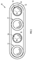
Figure 2 shows a plan view of the liquid dispensing apparatus and containers as shown inFigure 1 ; -
Figure 3 shows a front view of the liquid dispensing apparatus and containers as shown inFigure 1 ; -
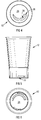
Figure 4 shows a top view of one of the containers as shown inFigure 1 ; -
Figure 5 shows a side view of the container ofFigure 4 ; -
Figure 6 shows a bottom view of the container ofFigure 4 ; -
Figure 7 shows a top perspective view of the container ofFigure 4 ; -
Figure 8 shows a bottom perspective view of the container ofFigure 4 ; -
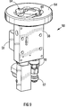
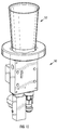
Figure 9 shows an isometric view of a part of a liquid dispensing apparatus of a second embodiment of a liquid dispensing system, in accordance with the invention; -
Figure 10 shows an isometric view of the part of the liquid dispensing apparatus ofFigure 1 , having a container, that forms a part of the second embodiment of the liquid dispensing system of the invention, located thereon; -
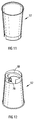
Figure 11 shows a top perspective view of the container as shown inFigure 10 ; -
Figure 12 shows a bottom perspective view of the container ofFigure 10 ; -
Figure 13 shows a side view of the container ofFigure 10 ; -
Figure 14 shows a cross-sectional side view of the container ofFigure 10 ; and -
Figure 15 shows a top plan view of the container ofFigure 10 . - Referring initially to
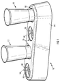
Figures 1 to 8 of the drawings, a first embodiment of a liquid dispensing system, in accordance with the invention, includes a dispensing apparatus designated generally by thereference numeral 10 and containers designated generally by thereference numeral 12, the containers being configured as described hereafter in order to permit dispensing of, for example, a carbonated beverage, beer, or the like, from a storage container via thedispensing apparatus 10 into acontainer 12. - The liquid dispensing
apparatus 10 includes abase structure 14 which can be positioned on or mounted on a suitable support surface, theapparatus 10 being configured particularly to permit dispensing of liquid simultaneously into four containers. It must be understood in this regard that different dispensing apparatus can be provided which will permit dispensing of liquid simultaneously into any alternative number of containers, as may be required for different practical applications. - The
base structure 14 accordingly defines four receiving and locatingformations 16 that are configured to receive and locate the bottom end of acontainer 12 therein, eachformation 16 being associated with anozzle 18 whereby a liquid can be dispensed into a container, the mode of support of a container and actual dispensing of a liquid into a container being described in more detail hereafter. - All the
nozzles 18 are connected in liquid communication with a liquid storage container (not shown), i.e. a storage container containing the liquid to be dispensed, the storage container typically being located at a remote location from thedispensing apparatus 10. In order to provide for the displacement of a liquid from a storage container via anozzle 18 into acontainer 12, the liquid contained in a storage container may be under pressure or, alternatively, the storage container may be located at an elevated level above the dispensing apparatus in order to provide for a gravity feed of liquid therefrom. Still alternatively, the dispensing apparatus may include a suitable liquid displacement means, e.g. a pump, which is operable to displace liquid from a liquid storage container into acontainer 12 via anozzle 18 of the dispensing apparatus. This relationship between the liquid dispensing apparatus and a liquid storage container will be apparent to those skilled in the art and, as such, is not described further herein. - The dispensing
apparatus 10 further includes control means (not shown) for controlling dispensing of a liquid into a container, the control means typically being electronically operable and controlling the flow of liquid through each particular nozzle through which a liquid should be dispensed into a container and also the volume of liquid to be dispensed into a container. Many different configuration control means are envisaged and may be associated with different configuration dispensing apparatus and, once again, this is not described in further detail herein. - As is illustrated clearly in
Figures 1 to 3 of the drawings, each receiving and locatingformation 16 comprises a recess formation having diametrically opposite locatingpins 20 projecting towards one another as shown, thepins 20 being configured to cooperate withformations 22 defined within the base region of a container, operatively beneath the base wall of the container, for locating the container within aformation 16. Thepins 20 and theformations 22, as shown, are configured to cooperate in a bayonet-type fashion to provide for the required location of acontainer 12 in aformation 16 in order to permit dispensing of a liquid into the container. Thebase wall 24 of eachcontainer 12 has a charging opening defined by apassage formation 26 that leads into the interior of the container above thebase wall 24 from anopening 28 defined within thebase wall 24, the passage formation having a one-way valve 30 (not clearly illustrated) located therein. The one-way valve 30 is a known type silicone flap-type valve that permits the insertion of anozzle 18 into the passage formation beyond the valve and, as such, dispensing of a liquid into acontainer 12 via the nozzle, when so located. The location of anozzle 18 into apassage formation 26 will occur as part of the locating process of acontainer 12 within aformation 16, which involves also the engagement of thepins 20 andformations 22 as described. The reverse operation will be effected after a container has been filled with a liquid, to permit removal of a container from the dispensing apparatus. Upon the withdrawal of anozzle 18 from apassage formation 26, the one-way valve 30 will effectively block the passage formation, thus sealing the base wall of the container and ensuring the required retention of liquid within the container. While anozzle 18 penetrates the one-way valve 30, it will form a seal around then nozzle. - Once again and as above suggested, the exact filling operation of
containers 12 is greatly variable while still incorporating the use of apparatus and containers including the essential principles of the invention as hereinabove described and which provides for "bottom filling" of containers as opposed to conventional "top filling" of containers via nozzles located above the open top ends of containers. - It is clear that the overall construction of the liquid dispensing apparatus and of containers for use with this apparatus as part of a liquid dispensing system, in accordance with the invention, can be varied in various different respects, while still accommodating the essential principles of the system which provide essentially for "bottom filling" of containers which, particularly in relation to carbonated beverages, beer, and the like, can be effected significantly quicker than "top filling" of containers, particularly because the formation of a foam head on the liquid filled into a container need not be a major consideration and does not affect the rate of filling a container.
- In relation to different forms of apparatus, the apparatus can include an integrated dispensing unit which incorporates a dispensing nozzle, a receiving and location formation for a container, control means for controlling the volume of liquid dispensed into a container, which typically includes a flow meter, and a connector arrangement for connecting the dispensing nozzle thereof to a liquid supply line. Such a dispensing unit can then be associated with any suitable base structure or means for its support in a configuration in which it can be used for dispensing a liquid. Typically, a plurality of dispensing units as envisaged can be mounted into a base structure which can be supported on a support surface, so that with all the connector arrangements of the units connected to a liquid supply line, a liquid dispensing apparatus is provided which is essentially the equivalent of the
apparatus 10. - Referring now also to
Figures 9 to 15 of the drawings, a dispensing unit as above envisaged as part of a liquid dispensing apparatus is designated generally by thereference numeral 50, whereas a container for use with the unit is designated generally by thereference numeral 52. Thedispensing unit 50 includes a locatingring 54, an on/offvalve assembly 56, control circuitry carried within ahousing 58, anelectronic flow meter 60 and aconnector arrangement 62, all the above parts being integrated with one another in the configuration illustrated for forming theunit 50. - The locating
ring 54 defines a receiving and locatingformation 64 within which the base region of thecontainer 52 is receivable as shown inFigure 10 , particularly in a configuration in which a dispensing nozzle (not shown but being essentially the equivalent of thenozzle 18 of the dispensingapparatus 10 as above described) can penetrate into the interior of thecontainer 52 via a charging opening and a one-way valve, as is already herein envisaged. The receiving and locatingformation 64 defines guide formations therein, designated generally by thenumeral 66, which are configured to cooperate with complementary formations, designated generally by thenumeral 68, in the base region of thecontainer 52 for guiding the displacement of the dispensing nozzle with respect to the container, particularly through rotation of the container while bearing downwardly thereon, which will provide for the dispensing nozzle to enter apassage 70 and pass through the passage into the container via a one-way valve 72 (not shown in detail). It will thus be understood that with the connector arrangement connected to a liquid supply line, through the operation of the control circuitry, a liquid will be dispensed into thecontainer 52, particularly a predetermined controlled volume of this liquid which will provide for the liquid container to be effectively filled thereby. - The
container 52 clearly is configured specifically to cooperate with the dispensingunit 50, particularly in relation to its location within the receiving and locatingformation 64, which provides for the dispensing nozzle of the unit to penetrate into the container to permit filling thereof. By the removal of the container from theunit 50, by reverse manipulation, the dispensing nozzle will withdraw from the container while the flap valve will be acted upon by the liquid contained in the container for blocking the charging opening leading into the container, thus ensuring that liquid cannot leak from the container. The overall construction of thecontainer 52 is thus essentially equivalent to that of thecontainer 12 described above, except insofar as its base region is specifically configured to cooperate with the dispensingunit 50. This is thus not described in any further detail herein. - It will be appreciated that dispensing units can be conveniently mounted into any suitable base structure in a configuration in which the locating rings thereof are disposed to facilitate the base region of containers to be received and located therein, it being envisaged that base structures can be configured to accommodate various different numbers of dispensing units, as will be determined by dispensing requirements. When combined with a base structure, as referred to above, a liquid dispensing apparatus is provided which is essentially the equivalent of the
apparatus 10 as above described. The exact configuration of the dispensingunit 50 and any base structure associated therewith can be varied in many different respects, while the mode of cooperation between the unit and containers to be used therewith also can be varied.
Claims (6)
- A liquid dispensing system, which includes a liquid dispensing apparatus (10, 50) including a connector arrangement for connecting a dispensing nozzle to a liquid supply container, and containers (12, 52) configured for use with the apparatus (10, 50);
the liquid dispensing apparatus (10, 50) having a base structure that defines at least one receiving and locating formation (16, 64) within which the dispensing nozzle (18) is located; and
each container (12, 52) including, in its base region, a charging opening (28, 70) and a one-way valve (30, 72) located in the charging opening (28, 70) for dispensing of a liquid into the container (12, 52);
the dispensing nozzle (18) being located within the receiving and locating formation (16, 64) to penetrate the container (12, 52) which is located within the receiving and locating formation, via its charging opening (28, 70) and one-way valve (30, 72);
the receiving and locating formation (16, 64) defines guide formations (20, 66) therein, which are configured to cooperate with complementary guide formations (22, 68) in the base region of the container (12, 52) for guiding the displacement of the dispensing nozzle (18) with respect to the container (12, 52) through rotation of the container (12, 52) such that the dispensing nozzle (18) penetrates the charging opening (28, 70) and the one-way valve (30, 72) to allow dispensing of the liquid into the container (12, 52); and
the one-way valve (30, 72) being configured to form a seal around the dispensing nozzle (18) when the dispensing nozzle (18) penetrates the one-way valve (30, 72) and to seal the charging opening (28, 70) when the dispensing nozzle (18) is retracted from the charging opening (28, 70) in use by counter-rotation of the container (12, 52) relative to the dispensing nozzle (18). - A liquid dispensing system as claimed in Claim 1, in which the dispensing apparatus (10, 50) includes control means (56, 58, 60, 62) for controlling the dispensing of a liquid into a container (12, 52).
- A liquid dispensing system as claimed in Claim 2, in which the control means (56, 58, 60, 62) provides for a fixed volume of liquid to be dispensed into a container (12, 52).
- A liquid dispensing system as claimed in any one of the preceding claims, in which the liquid dispensing apparatus (10, 50) includes a base structure that defines a plurality of receiving and locating formations (16, 64).
- A liquid dispensing apparatus for use in a liquid dispensing system as claimed in any one of Claims 1 to 4, including a connector arrangement for connecting a dispensing nozzle to a liquid supply container, the liquid dispensing apparatus (10, 50) having a base structure that defines at least one receiving and locating formation (16, 64) within which the dispensing nozzle (18) is located for penetrating a container; the receiving and locating formation (16, 64) defines guide formations (20, 66) therein, which are configured to cooperate with complementary guide formations (22, 68) in the base region of the container (12, 52) for guiding the displacement of the dispensing nozzle (18) with respect to the container (12, 52) through rotation of the container (12, 52) such that the dispensing nozzle (18) penetrates a charging opening (28, 70) and a one-way valve (30, 72) of the container to allow dispensing of the liquid into the container (12, 52).
- A container for use in a liquid dispensing system as claimed in any one of Claims 1 to 4, the container (12, 52) including, in its base region, a charging opening (28, 70), a one-way valve (30, 72) located in the charging opening (28, 70) for dispensing of a liquid into the container (12, 52), and complementary guide formations (22, 68) configured to cooperate with guide formations (20, 66) defined by the receiving and locating formation (16, 64) of the liquid dispensing apparatus for guiding the displacement of the dispensing nozzle (18) with respect to the container (12, 52) through rotation of the container (12, 52) such that the dispensing nozzle (18) penetrates the charging opening (28, 70) and the one-way valve (30, 72) to allow dispensing of the liquid into the container (12, 52); and the one-way valve (30, 72) being configured to form a seal around the dispensing nozzle (18) when the dispensing nozzle (18) penetrates the one-way valve (30, 72) and to seal the charging opening (28, 70) when the dispensing nozzle (18) is retracted from the charging opening (28, 70) in use by counter-rotation of the container (12, 52) relative to the dispensing nozzle (18).
Applications Claiming Priority (2)
| Application Number | Priority Date | Filing Date | Title |
|---|---|---|---|
| ZA200604626 | 2006-06-06 | ||
| PCT/IB2007/052066 WO2007141719A1 (en) | 2006-06-06 | 2007-06-01 | A liquid dispensing system |
Publications (2)
| Publication Number | Publication Date |
|---|---|
| EP2029470A1 EP2029470A1 (en) | 2009-03-04 |
| EP2029470B1 true EP2029470B1 (en) | 2016-08-17 |
Family
ID=38596827
Family Applications (1)
| Application Number | Title | Priority Date | Filing Date |
|---|---|---|---|
| EP07736066.7A Not-in-force EP2029470B1 (en) | 2006-06-06 | 2007-06-01 | A liquid dispensing system |
Country Status (5)
| Country | Link |
|---|---|
| US (1) | US8151838B2 (en) |
| EP (1) | EP2029470B1 (en) |
| AU (1) | AU2007257569B2 (en) |
| WO (1) | WO2007141719A1 (en) |
| ZA (1) | ZA200810795B (en) |
Cited By (3)
| Publication number | Priority date | Publication date | Assignee | Title |
|---|---|---|---|---|
| WO2019078748A1 (en) | 2017-10-20 | 2019-04-25 | Novadelta - Comércio E Indústria De Cafés, Lda | Beverage preparation system with beverage receptacle retention |
| US11325820B2 (en) | 2018-08-01 | 2022-05-10 | Novadelta-Comércio E Indéstria De Cafés, Lda | Beverage distribution system with composed drinking recipients, and process of operation thereof |
| US11524884B2 (en) | 2018-08-01 | 2022-12-13 | Novadelta—Comércio E Indústria De Cafés, Lda | Beverage distribution system with ergonomic retention of drinking recipients, and process of operation thereof |
Families Citing this family (26)
| Publication number | Priority date | Publication date | Assignee | Title |
|---|---|---|---|---|
| NZ621685A (en) * | 2008-05-20 | 2014-07-25 | Grinon Ind | Fluid transfer assembly and methods of fluid transfer |
| US8777182B2 (en) | 2008-05-20 | 2014-07-15 | Grinon Industries | Fluid transfer assembly and methods of fluid transfer |
| EP2539229A4 (en) * | 2010-02-26 | 2014-06-11 | Manitowoc Foodservice Co Inc | Dispensing system and method of controlling the system |
| DE102011052032A1 (en) * | 2011-07-21 | 2013-01-24 | Inuma Fahrzeug-Service Und Maschinenbau Gmbh | Adapter element for nozzle unit for exhausting liquid, has sensor for monitoring flow of liquid through nozzle unit, where sensor is formed as thermal flow monitoring sensor or thermal anemometer |
| BR112014016248B1 (en) | 2011-12-30 | 2020-12-22 | Grinon Industries | fluid container; method for coupling a container connection device to a fluid container; and dispensing system |
| US9016333B2 (en) * | 2013-01-02 | 2015-04-28 | General Electric Company | Bottom fill kitchen sink feature |
| JP6105343B2 (en) * | 2013-03-19 | 2017-03-29 | 有限会社ユタカ産業 | Beverage cup body |
| JP5650779B2 (en) * | 2013-03-26 | 2015-01-07 | 有限会社ユタカ産業 | Stopper with check valve |
| KR101656422B1 (en) * | 2014-06-17 | 2016-09-12 | (주)제이알피코퍼레이션 | Bottle for beverage |
| CN104310292A (en) * | 2014-10-11 | 2015-01-28 | 北京维佳创机电控制技术有限公司 | Beer discharging device |
| CH710343A1 (en) | 2014-11-07 | 2016-05-13 | Ip Évolution Sa | Cup for filling from below and connection device for the cup. |
| FR3035100B1 (en) * | 2015-04-14 | 2021-01-29 | Olivier Bernard Sylvain Jammes | DEVICE FOR FILLING A BEVERAGE CONTAINER, IN PARTICULAR FROM ITS BOTTOM |
| KR20160133129A (en) * | 2015-05-12 | 2016-11-22 | 엔피씨(주) | Bottle for beverage and dispenser assembly of beverage and manufacturing method of bottle for beverage |
| KR101682616B1 (en) * | 2015-05-12 | 2016-12-05 | 엔피씨(주) | Injection apparatus for beverage |
| CN104840064B (en) * | 2015-05-18 | 2017-05-03 | 王龙 | Bottom filling type beer machine |
| US10759644B2 (en) * | 2015-05-21 | 2020-09-01 | Pepsico, Inc. | Digital table |
| DE202015106931U1 (en) * | 2015-12-18 | 2016-01-15 | Dirk Bolender | Container for holding drinks and device for filling the container |
| JP6768332B2 (en) * | 2016-04-08 | 2020-10-14 | 有限会社ユタカ産業 | Container body |
| US9742889B1 (en) * | 2016-06-07 | 2017-08-22 | Cherokee Nation Entertainment, Llc | Lighted phone charger and cup holder device |
| CN106180102B (en) * | 2016-07-14 | 2018-09-18 | 珠海优特物联科技有限公司 | A kind of cup body and its driving device |
| EP3281567A1 (en) * | 2016-08-08 | 2018-02-14 | RIPRUP Company S.A. | Intelligent carafe |
| AU2019234539A1 (en) * | 2018-03-12 | 2020-10-08 | Grinon Industries | Beverage dispensing systems and methods thereof |
| BR112021003567A2 (en) * | 2018-08-30 | 2021-05-18 | Hewlett-Packard Development Company, L.P. | replacement of printing materials |
| US11738986B2 (en) * | 2021-02-16 | 2023-08-29 | Aquaphant, Inc. | Refillable bottle |
| CN111743364A (en) * | 2020-07-14 | 2020-10-09 | 上海电机学院 | Air pressure water pumping type vacuum cup and using method thereof |
| US11530868B2 (en) * | 2021-01-21 | 2022-12-20 | Haier Us Appliance Solutions, Inc. | Herb storage assembly for a refrigerator appliance |
Family Cites Families (6)
| Publication number | Priority date | Publication date | Assignee | Title |
|---|---|---|---|---|
| US3601164A (en) * | 1969-03-03 | 1971-08-24 | Sterigard Corp | Apparatus for injecting propellant into a dispensing container |
| DE8307900U1 (en) * | 1983-03-18 | 1984-07-19 | Wella Ag, 6100 Darmstadt | Self-closing bottom valve of a receptacle for pasty or liquid substances |
| GB2137171A (en) | 1983-03-23 | 1984-10-03 | Growers Requisites Northern Li | Collapsible boxes or trays |
| US20040256401A1 (en) | 2003-06-19 | 2004-12-23 | Chodosh David Jeffrey | Beverage container attachment |
| US6883564B2 (en) * | 2003-07-22 | 2005-04-26 | Thomas M. Risch | Pressurizing system for a dispensing container |
| IES20060165A2 (en) | 2006-03-06 | 2007-05-16 | Charles Russell | Drinking vessel and method and apparatus for dispensing a beverage |
-
2007
- 2007-06-01 WO PCT/IB2007/052066 patent/WO2007141719A1/en active Application Filing
- 2007-06-01 US US12/303,739 patent/US8151838B2/en active Active
- 2007-06-01 AU AU2007257569A patent/AU2007257569B2/en not_active Ceased
- 2007-06-01 EP EP07736066.7A patent/EP2029470B1/en not_active Not-in-force
-
2008
- 2008-12-22 ZA ZA2008/10795A patent/ZA200810795B/en unknown
Non-Patent Citations (1)
| Title |
|---|
| None * |
Cited By (3)
| Publication number | Priority date | Publication date | Assignee | Title |
|---|---|---|---|---|
| WO2019078748A1 (en) | 2017-10-20 | 2019-04-25 | Novadelta - Comércio E Indústria De Cafés, Lda | Beverage preparation system with beverage receptacle retention |
| US11325820B2 (en) | 2018-08-01 | 2022-05-10 | Novadelta-Comércio E Indéstria De Cafés, Lda | Beverage distribution system with composed drinking recipients, and process of operation thereof |
| US11524884B2 (en) | 2018-08-01 | 2022-12-13 | Novadelta—Comércio E Indústria De Cafés, Lda | Beverage distribution system with ergonomic retention of drinking recipients, and process of operation thereof |
Also Published As
| Publication number | Publication date |
|---|---|
| US20100230007A1 (en) | 2010-09-16 |
| AU2007257569B2 (en) | 2012-02-02 |
| AU2007257569A1 (en) | 2007-12-13 |
| EP2029470A1 (en) | 2009-03-04 |
| US8151838B2 (en) | 2012-04-10 |
| WO2007141719A1 (en) | 2007-12-13 |
| ZA200810795B (en) | 2012-02-29 |
Similar Documents
| Publication | Publication Date | Title |
|---|---|---|
| EP2029470B1 (en) | A liquid dispensing system | |
| JP2019116322A (en) | Dispenser having cartridge holder, system and method with use thereof | |
| KR101545349B1 (en) | Beverage machine and piercing member for an opening device of a beverage machine | |
| JP3892398B2 (en) | Equipment water infuser to prepare beverage from capsule | |
| US20130149424A1 (en) | Brewing device for extracting a portion capsule, method for operating a brewing device and use of a brewing device | |
| US20170311750A1 (en) | Beverage producing system and capsule | |
| CN100376815C (en) | Lubricating-fluid infusion apparatus | |
| CN102015471A (en) | An automatic pod conveyor and brewer assembly for fresh hot beverage | |
| RU2615626C2 (en) | Dosing device equipped with device for reservoir placement | |
| EP0102527A2 (en) | Beverage dispenser | |
| US10875757B2 (en) | Beverage extractor for sparkling beverages | |
| CN105263375A (en) | Capsule machine and components | |
| WO2007042486A3 (en) | Cartridge, device and process for preparing an infused beverage | |
| JP2009528956A (en) | Drinking container that can be poured from bottom and device for dispensing beverage | |
| EP2888183B1 (en) | A capsule for use with a food preparation machine | |
| CN104244777A (en) | A capsule holder for a beverage preparation machine | |
| JP2019518677A (en) | Beverage container cap for use with a beverage extractor | |
| EP2892825B1 (en) | A beverage capsule with safety feature | |
| US20190152756A1 (en) | Vessel extraction apparatus and vessel therefore | |
| EP3199071A1 (en) | System for preparing a liquid beverage from a capsule | |
| US4274557A (en) | Beverage dispenser pumping system | |
| EP3297947B1 (en) | An apparatus for storing and dispensing liquid from a liquid retaining bag | |
| US20230337850A1 (en) | Beverage preparation machine and method for preparing a beverage with such a beverage preparation machine | |
| US9451848B2 (en) | Beverage dispenser and coffee maker | |
| WO2008072240A2 (en) | Apparatus for maintaining co2 in a bottle containing a carbonated beverage |
Legal Events
| Date | Code | Title | Description |
|---|---|---|---|
| PUAI | Public reference made under article 153(3) epc to a published international application that has entered the european phase |
Free format text: ORIGINAL CODE: 0009012 |
|
| 17P | Request for examination filed |
Effective date: 20090105 |
|
| AK | Designated contracting states |
Kind code of ref document: A1 Designated state(s): AT BE BG CH CY CZ DE DK EE ES FI FR GB GR HU IE IS IT LI LT LU LV MC MT NL PL PT RO SE SI SK TR |
|
| AX | Request for extension of the european patent |
Extension state: AL BA HR MK RS |
|
| DAX | Request for extension of the european patent (deleted) | ||
| 17Q | First examination report despatched |
Effective date: 20130131 |
|
| GRAP | Despatch of communication of intention to grant a patent |
Free format text: ORIGINAL CODE: EPIDOSNIGR1 |
|
| INTG | Intention to grant announced |
Effective date: 20160217 |
|
| GRAR | Information related to intention to grant a patent recorded |
Free format text: ORIGINAL CODE: EPIDOSNIGR71 |
|
| GRAS | Grant fee paid |
Free format text: ORIGINAL CODE: EPIDOSNIGR3 |
|
| GRAA | (expected) grant |
Free format text: ORIGINAL CODE: 0009210 |
|
| AK | Designated contracting states |
Kind code of ref document: B1 Designated state(s): AT BE BG CH CY CZ DE DK EE ES FI FR GB GR HU IE IS IT LI LT LU LV MC MT NL PL PT RO SE SI SK TR |
|
| INTG | Intention to grant announced |
Effective date: 20160711 |
|
| REG | Reference to a national code |
Ref country code: GB Ref legal event code: FG4D |
|
| REG | Reference to a national code |
Ref country code: CH Ref legal event code: EP |
|
| REG | Reference to a national code |
Ref country code: IE Ref legal event code: FG4D |
|
| REG | Reference to a national code |
Ref country code: AT Ref legal event code: REF Ref document number: 820866 Country of ref document: AT Kind code of ref document: T Effective date: 20160915 |
|
| REG | Reference to a national code |
Ref country code: DE Ref legal event code: R096 Ref document number: 602007047500 Country of ref document: DE |
|
| REG | Reference to a national code |
Ref country code: NL Ref legal event code: FP |
|
| REG | Reference to a national code |
Ref country code: LT Ref legal event code: MG4D |
|
| REG | Reference to a national code |
Ref country code: AT Ref legal event code: MK05 Ref document number: 820866 Country of ref document: AT Kind code of ref document: T Effective date: 20160817 |
|
| PG25 | Lapsed in a contracting state [announced via postgrant information from national office to epo] |
Ref country code: LT Free format text: LAPSE BECAUSE OF FAILURE TO SUBMIT A TRANSLATION OF THE DESCRIPTION OR TO PAY THE FEE WITHIN THE PRESCRIBED TIME-LIMIT Effective date: 20160817 Ref country code: FI Free format text: LAPSE BECAUSE OF FAILURE TO SUBMIT A TRANSLATION OF THE DESCRIPTION OR TO PAY THE FEE WITHIN THE PRESCRIBED TIME-LIMIT Effective date: 20160817 Ref country code: IT Free format text: LAPSE BECAUSE OF FAILURE TO SUBMIT A TRANSLATION OF THE DESCRIPTION OR TO PAY THE FEE WITHIN THE PRESCRIBED TIME-LIMIT Effective date: 20160817 |
|
| PG25 | Lapsed in a contracting state [announced via postgrant information from national office to epo] |
Ref country code: AT Free format text: LAPSE BECAUSE OF FAILURE TO SUBMIT A TRANSLATION OF THE DESCRIPTION OR TO PAY THE FEE WITHIN THE PRESCRIBED TIME-LIMIT Effective date: 20160817 Ref country code: SE Free format text: LAPSE BECAUSE OF FAILURE TO SUBMIT A TRANSLATION OF THE DESCRIPTION OR TO PAY THE FEE WITHIN THE PRESCRIBED TIME-LIMIT Effective date: 20160817 Ref country code: ES Free format text: LAPSE BECAUSE OF FAILURE TO SUBMIT A TRANSLATION OF THE DESCRIPTION OR TO PAY THE FEE WITHIN THE PRESCRIBED TIME-LIMIT Effective date: 20160817 Ref country code: GR Free format text: LAPSE BECAUSE OF FAILURE TO SUBMIT A TRANSLATION OF THE DESCRIPTION OR TO PAY THE FEE WITHIN THE PRESCRIBED TIME-LIMIT Effective date: 20161118 Ref country code: LV Free format text: LAPSE BECAUSE OF FAILURE TO SUBMIT A TRANSLATION OF THE DESCRIPTION OR TO PAY THE FEE WITHIN THE PRESCRIBED TIME-LIMIT Effective date: 20160817 Ref country code: PL Free format text: LAPSE BECAUSE OF FAILURE TO SUBMIT A TRANSLATION OF THE DESCRIPTION OR TO PAY THE FEE WITHIN THE PRESCRIBED TIME-LIMIT Effective date: 20160817 Ref country code: PT Free format text: LAPSE BECAUSE OF FAILURE TO SUBMIT A TRANSLATION OF THE DESCRIPTION OR TO PAY THE FEE WITHIN THE PRESCRIBED TIME-LIMIT Effective date: 20161219 |
|
| PG25 | Lapsed in a contracting state [announced via postgrant information from national office to epo] |
Ref country code: EE Free format text: LAPSE BECAUSE OF FAILURE TO SUBMIT A TRANSLATION OF THE DESCRIPTION OR TO PAY THE FEE WITHIN THE PRESCRIBED TIME-LIMIT Effective date: 20160817 Ref country code: RO Free format text: LAPSE BECAUSE OF FAILURE TO SUBMIT A TRANSLATION OF THE DESCRIPTION OR TO PAY THE FEE WITHIN THE PRESCRIBED TIME-LIMIT Effective date: 20160817 |
|
| REG | Reference to a national code |
Ref country code: DE Ref legal event code: R097 Ref document number: 602007047500 Country of ref document: DE |
|
| PG25 | Lapsed in a contracting state [announced via postgrant information from national office to epo] |
Ref country code: CZ Free format text: LAPSE BECAUSE OF FAILURE TO SUBMIT A TRANSLATION OF THE DESCRIPTION OR TO PAY THE FEE WITHIN THE PRESCRIBED TIME-LIMIT Effective date: 20160817 Ref country code: DK Free format text: LAPSE BECAUSE OF FAILURE TO SUBMIT A TRANSLATION OF THE DESCRIPTION OR TO PAY THE FEE WITHIN THE PRESCRIBED TIME-LIMIT Effective date: 20160817 Ref country code: BG Free format text: LAPSE BECAUSE OF FAILURE TO SUBMIT A TRANSLATION OF THE DESCRIPTION OR TO PAY THE FEE WITHIN THE PRESCRIBED TIME-LIMIT Effective date: 20161117 Ref country code: SK Free format text: LAPSE BECAUSE OF FAILURE TO SUBMIT A TRANSLATION OF THE DESCRIPTION OR TO PAY THE FEE WITHIN THE PRESCRIBED TIME-LIMIT Effective date: 20160817 Ref country code: BE Free format text: LAPSE BECAUSE OF FAILURE TO SUBMIT A TRANSLATION OF THE DESCRIPTION OR TO PAY THE FEE WITHIN THE PRESCRIBED TIME-LIMIT Effective date: 20160817 |
|
| REG | Reference to a national code |
Ref country code: FR Ref legal event code: PLFP Year of fee payment: 11 |
|
| PLBE | No opposition filed within time limit |
Free format text: ORIGINAL CODE: 0009261 |
|
| STAA | Information on the status of an ep patent application or granted ep patent |
Free format text: STATUS: NO OPPOSITION FILED WITHIN TIME LIMIT |
|
| 26N | No opposition filed |
Effective date: 20170518 |
|
| PG25 | Lapsed in a contracting state [announced via postgrant information from national office to epo] |
Ref country code: SI Free format text: LAPSE BECAUSE OF FAILURE TO SUBMIT A TRANSLATION OF THE DESCRIPTION OR TO PAY THE FEE WITHIN THE PRESCRIBED TIME-LIMIT Effective date: 20160817 |
|
| PG25 | Lapsed in a contracting state [announced via postgrant information from national office to epo] |
Ref country code: MC Free format text: LAPSE BECAUSE OF FAILURE TO SUBMIT A TRANSLATION OF THE DESCRIPTION OR TO PAY THE FEE WITHIN THE PRESCRIBED TIME-LIMIT Effective date: 20160817 |
|
| REG | Reference to a national code |
Ref country code: CH Ref legal event code: PL |
|
| REG | Reference to a national code |
Ref country code: IE Ref legal event code: MM4A |
|
| PG25 | Lapsed in a contracting state [announced via postgrant information from national office to epo] |
Ref country code: LI Free format text: LAPSE BECAUSE OF NON-PAYMENT OF DUE FEES Effective date: 20170630 Ref country code: CH Free format text: LAPSE BECAUSE OF NON-PAYMENT OF DUE FEES Effective date: 20170630 Ref country code: IE Free format text: LAPSE BECAUSE OF NON-PAYMENT OF DUE FEES Effective date: 20170601 Ref country code: LU Free format text: LAPSE BECAUSE OF NON-PAYMENT OF DUE FEES Effective date: 20170601 |
|
| REG | Reference to a national code |
Ref country code: FR Ref legal event code: PLFP Year of fee payment: 12 |
|
| PGFP | Annual fee paid to national office [announced via postgrant information from national office to epo] |
Ref country code: FR Payment date: 20180627 Year of fee payment: 12 |
|
| PG25 | Lapsed in a contracting state [announced via postgrant information from national office to epo] |
Ref country code: MT Free format text: LAPSE BECAUSE OF NON-PAYMENT OF DUE FEES Effective date: 20170601 |
|
| PGFP | Annual fee paid to national office [announced via postgrant information from national office to epo] |
Ref country code: ES Payment date: 20180702 Year of fee payment: 12 Ref country code: DE Payment date: 20180702 Year of fee payment: 12 |
|
| PG25 | Lapsed in a contracting state [announced via postgrant information from national office to epo] |
Ref country code: HU Free format text: LAPSE BECAUSE OF FAILURE TO SUBMIT A TRANSLATION OF THE DESCRIPTION OR TO PAY THE FEE WITHIN THE PRESCRIBED TIME-LIMIT; INVALID AB INITIO Effective date: 20070601 |
|
| PG25 | Lapsed in a contracting state [announced via postgrant information from national office to epo] |
Ref country code: CY Free format text: LAPSE BECAUSE OF NON-PAYMENT OF DUE FEES Effective date: 20160817 |
|
| REG | Reference to a national code |
Ref country code: DE Ref legal event code: R119 Ref document number: 602007047500 Country of ref document: DE |
|
| REG | Reference to a national code |
Ref country code: NL Ref legal event code: MM Effective date: 20190701 |
|
| PG25 | Lapsed in a contracting state [announced via postgrant information from national office to epo] |
Ref country code: TR Free format text: LAPSE BECAUSE OF FAILURE TO SUBMIT A TRANSLATION OF THE DESCRIPTION OR TO PAY THE FEE WITHIN THE PRESCRIBED TIME-LIMIT Effective date: 20160817 |
|
| PG25 | Lapsed in a contracting state [announced via postgrant information from national office to epo] |
Ref country code: DE Free format text: LAPSE BECAUSE OF NON-PAYMENT OF DUE FEES Effective date: 20200101 Ref country code: NL Free format text: LAPSE BECAUSE OF NON-PAYMENT OF DUE FEES Effective date: 20190701 |
|
| PG25 | Lapsed in a contracting state [announced via postgrant information from national office to epo] |
Ref country code: FR Free format text: LAPSE BECAUSE OF NON-PAYMENT OF DUE FEES Effective date: 20190630 |
|
| PG25 | Lapsed in a contracting state [announced via postgrant information from national office to epo] |
Ref country code: IS Free format text: LAPSE BECAUSE OF FAILURE TO SUBMIT A TRANSLATION OF THE DESCRIPTION OR TO PAY THE FEE WITHIN THE PRESCRIBED TIME-LIMIT Effective date: 20161217 |
|
| PGFP | Annual fee paid to national office [announced via postgrant information from national office to epo] |
Ref country code: GB Payment date: 20220627 Year of fee payment: 16 |
|
| GBPC | Gb: european patent ceased through non-payment of renewal fee |
Effective date: 20230601 |