EP2029265B1 - Ultraschallunterstütztes kontinuierliches Verfahren und Vorrichtung zur Dispersion von Nanofasern und Nanoröhrchen in Polymeren - Google Patents
Ultraschallunterstütztes kontinuierliches Verfahren und Vorrichtung zur Dispersion von Nanofasern und Nanoröhrchen in Polymeren Download PDFInfo
- Publication number
- EP2029265B1 EP2029265B1 EP07795740.5A EP07795740A EP2029265B1 EP 2029265 B1 EP2029265 B1 EP 2029265B1 EP 07795740 A EP07795740 A EP 07795740A EP 2029265 B1 EP2029265 B1 EP 2029265B1
- Authority
- EP
- European Patent Office
- Prior art keywords
- ultrasonic treatment
- polymer
- ultrasonic
- cnf
- zone
- Prior art date
- Legal status (The legal status is an assumption and is not a legal conclusion. Google has not performed a legal analysis and makes no representation as to the accuracy of the status listed.)
- Not-in-force
Links
Images


Classifications
-
- B—PERFORMING OPERATIONS; TRANSPORTING
- B29—WORKING OF PLASTICS; WORKING OF SUBSTANCES IN A PLASTIC STATE IN GENERAL
- B29B—PREPARATION OR PRETREATMENT OF THE MATERIAL TO BE SHAPED; MAKING GRANULES OR PREFORMS; RECOVERY OF PLASTICS OR OTHER CONSTITUENTS OF WASTE MATERIAL CONTAINING PLASTICS
- B29B7/00—Mixing; Kneading
- B29B7/30—Mixing; Kneading continuous, with mechanical mixing or kneading devices
- B29B7/34—Mixing; Kneading continuous, with mechanical mixing or kneading devices with movable mixing or kneading devices
- B29B7/38—Mixing; Kneading continuous, with mechanical mixing or kneading devices with movable mixing or kneading devices rotary
- B29B7/40—Mixing; Kneading continuous, with mechanical mixing or kneading devices with movable mixing or kneading devices rotary with single shaft
- B29B7/42—Mixing; Kneading continuous, with mechanical mixing or kneading devices with movable mixing or kneading devices rotary with single shaft with screw or helix
-
- B—PERFORMING OPERATIONS; TRANSPORTING
- B29—WORKING OF PLASTICS; WORKING OF SUBSTANCES IN A PLASTIC STATE IN GENERAL
- B29B—PREPARATION OR PRETREATMENT OF THE MATERIAL TO BE SHAPED; MAKING GRANULES OR PREFORMS; RECOVERY OF PLASTICS OR OTHER CONSTITUENTS OF WASTE MATERIAL CONTAINING PLASTICS
- B29B7/00—Mixing; Kneading
- B29B7/30—Mixing; Kneading continuous, with mechanical mixing or kneading devices
- B29B7/34—Mixing; Kneading continuous, with mechanical mixing or kneading devices with movable mixing or kneading devices
- B29B7/36—Mixing; Kneading continuous, with mechanical mixing or kneading devices with movable mixing or kneading devices shaking, oscillating or vibrating
-
- B—PERFORMING OPERATIONS; TRANSPORTING
- B29—WORKING OF PLASTICS; WORKING OF SUBSTANCES IN A PLASTIC STATE IN GENERAL
- B29B—PREPARATION OR PRETREATMENT OF THE MATERIAL TO BE SHAPED; MAKING GRANULES OR PREFORMS; RECOVERY OF PLASTICS OR OTHER CONSTITUENTS OF WASTE MATERIAL CONTAINING PLASTICS
- B29B7/00—Mixing; Kneading
- B29B7/30—Mixing; Kneading continuous, with mechanical mixing or kneading devices
- B29B7/58—Component parts, details or accessories; Auxiliary operations
- B29B7/72—Measuring, controlling or regulating
- B29B7/726—Measuring properties of mixture, e.g. temperature or density
-
- B—PERFORMING OPERATIONS; TRANSPORTING
- B29—WORKING OF PLASTICS; WORKING OF SUBSTANCES IN A PLASTIC STATE IN GENERAL
- B29B—PREPARATION OR PRETREATMENT OF THE MATERIAL TO BE SHAPED; MAKING GRANULES OR PREFORMS; RECOVERY OF PLASTICS OR OTHER CONSTITUENTS OF WASTE MATERIAL CONTAINING PLASTICS
- B29B7/00—Mixing; Kneading
- B29B7/80—Component parts, details or accessories; Auxiliary operations
- B29B7/88—Adding charges, i.e. additives
- B29B7/90—Fillers or reinforcements, e.g. fibres
-
- B—PERFORMING OPERATIONS; TRANSPORTING
- B29—WORKING OF PLASTICS; WORKING OF SUBSTANCES IN A PLASTIC STATE IN GENERAL
- B29C—SHAPING OR JOINING OF PLASTICS; SHAPING OF MATERIAL IN A PLASTIC STATE, NOT OTHERWISE PROVIDED FOR; AFTER-TREATMENT OF THE SHAPED PRODUCTS, e.g. REPAIRING
- B29C48/00—Extrusion moulding, i.e. expressing the moulding material through a die or nozzle which imparts the desired form; Apparatus therefor
- B29C48/14—Extrusion moulding, i.e. expressing the moulding material through a die or nozzle which imparts the desired form; Apparatus therefor characterised by the particular extruding conditions, e.g. in a modified atmosphere or by using vibration
- B29C48/142—Extrusion moulding, i.e. expressing the moulding material through a die or nozzle which imparts the desired form; Apparatus therefor characterised by the particular extruding conditions, e.g. in a modified atmosphere or by using vibration using force fields, e.g. gravity or electrical fields
-
- B—PERFORMING OPERATIONS; TRANSPORTING
- B29—WORKING OF PLASTICS; WORKING OF SUBSTANCES IN A PLASTIC STATE IN GENERAL
- B29C—SHAPING OR JOINING OF PLASTICS; SHAPING OF MATERIAL IN A PLASTIC STATE, NOT OTHERWISE PROVIDED FOR; AFTER-TREATMENT OF THE SHAPED PRODUCTS, e.g. REPAIRING
- B29C48/00—Extrusion moulding, i.e. expressing the moulding material through a die or nozzle which imparts the desired form; Apparatus therefor
- B29C48/25—Component parts, details or accessories; Auxiliary operations
- B29C48/285—Feeding the extrusion material to the extruder
- B29C48/287—Raw material pre-treatment while feeding
-
- B—PERFORMING OPERATIONS; TRANSPORTING
- B29—WORKING OF PLASTICS; WORKING OF SUBSTANCES IN A PLASTIC STATE IN GENERAL
- B29C—SHAPING OR JOINING OF PLASTICS; SHAPING OF MATERIAL IN A PLASTIC STATE, NOT OTHERWISE PROVIDED FOR; AFTER-TREATMENT OF THE SHAPED PRODUCTS, e.g. REPAIRING
- B29C48/00—Extrusion moulding, i.e. expressing the moulding material through a die or nozzle which imparts the desired form; Apparatus therefor
- B29C48/25—Component parts, details or accessories; Auxiliary operations
- B29C48/285—Feeding the extrusion material to the extruder
- B29C48/288—Feeding the extrusion material to the extruder in solid form, e.g. powder or granules
-
- B—PERFORMING OPERATIONS; TRANSPORTING
- B29—WORKING OF PLASTICS; WORKING OF SUBSTANCES IN A PLASTIC STATE IN GENERAL
- B29C—SHAPING OR JOINING OF PLASTICS; SHAPING OF MATERIAL IN A PLASTIC STATE, NOT OTHERWISE PROVIDED FOR; AFTER-TREATMENT OF THE SHAPED PRODUCTS, e.g. REPAIRING
- B29C48/00—Extrusion moulding, i.e. expressing the moulding material through a die or nozzle which imparts the desired form; Apparatus therefor
- B29C48/25—Component parts, details or accessories; Auxiliary operations
- B29C48/36—Means for plasticising or homogenising the moulding material or forcing it through the nozzle or die
- B29C48/395—Means for plasticising or homogenising the moulding material or forcing it through the nozzle or die using screws surrounded by a cooperating barrel, e.g. single screw extruders
- B29C48/397—Means for plasticising or homogenising the moulding material or forcing it through the nozzle or die using screws surrounded by a cooperating barrel, e.g. single screw extruders using a single screw
-
- B—PERFORMING OPERATIONS; TRANSPORTING
- B29—WORKING OF PLASTICS; WORKING OF SUBSTANCES IN A PLASTIC STATE IN GENERAL
- B29C—SHAPING OR JOINING OF PLASTICS; SHAPING OF MATERIAL IN A PLASTIC STATE, NOT OTHERWISE PROVIDED FOR; AFTER-TREATMENT OF THE SHAPED PRODUCTS, e.g. REPAIRING
- B29C48/00—Extrusion moulding, i.e. expressing the moulding material through a die or nozzle which imparts the desired form; Apparatus therefor
- B29C48/25—Component parts, details or accessories; Auxiliary operations
- B29C48/36—Means for plasticising or homogenising the moulding material or forcing it through the nozzle or die
- B29C48/395—Means for plasticising or homogenising the moulding material or forcing it through the nozzle or die using screws surrounded by a cooperating barrel, e.g. single screw extruders
- B29C48/40—Means for plasticising or homogenising the moulding material or forcing it through the nozzle or die using screws surrounded by a cooperating barrel, e.g. single screw extruders using two or more parallel screws or at least two parallel non-intermeshing screws, e.g. twin screw extruders
- B29C48/405—Intermeshing co-rotating screws
-
- B—PERFORMING OPERATIONS; TRANSPORTING
- B29—WORKING OF PLASTICS; WORKING OF SUBSTANCES IN A PLASTIC STATE IN GENERAL
- B29C—SHAPING OR JOINING OF PLASTICS; SHAPING OF MATERIAL IN A PLASTIC STATE, NOT OTHERWISE PROVIDED FOR; AFTER-TREATMENT OF THE SHAPED PRODUCTS, e.g. REPAIRING
- B29C48/00—Extrusion moulding, i.e. expressing the moulding material through a die or nozzle which imparts the desired form; Apparatus therefor
- B29C48/25—Component parts, details or accessories; Auxiliary operations
- B29C48/36—Means for plasticising or homogenising the moulding material or forcing it through the nozzle or die
- B29C48/50—Details of extruders
- B29C48/505—Screws
- B29C48/625—Screws characterised by the ratio of the threaded length of the screw to its outside diameter [L/D ratio]
Definitions
- the present invention relates to a process for producing high performance polymer composites.
- Such polymer composites being made from a combination of polymer and nanofibers and/or nanotubes where standard mixing methods limit the level of dispersion attainable.
- the ultrasonic treating method of the present invention allows a more highly dispersed polymer composite mixture which provides increased thermal, mechanical and electrical properties.
- High performance polymer nanocomposites are greatly influenced by the degree of dispersion of nanofibers and nanotubes.
- chemically dissimilar components are combined at the nanometer scale since they are too small to act as stress concentrators. Therefore, stronger interaction between the polymer and the nanofibers or nanotubes produces composites with significant enhancement of properties like strength, modulus, electrical conductivity, permeability, thermal resistance, and heat distortion temperature. In contrast to conventional composites, these effects take place at very low filler loadings (1 to 5 weight percent) leading to a significant weight reduction of products made from nanocomposites in comparison with currently used metal alloys and high performance fiber-reinforced composites.
- CNF/polyimide nanocomposites often exhibit properties superior to conventional fiber-reinforced composites.
- CNF/polyimide nanocomposites were studied.
- the CNF's are produced by the catalytic decomposition of hydrocarbons in the vapor phase at 500-1500°C. CNFs are readily aggregate and bundle together or become entangled. Dispersion of the individual fibers being the main obstacle for their use in many applications.
- the commonly used methods to disperse CNFs are mechanical, melt processing and plasma treatment. Among these methods ultrasonication of CNFs in solutions for a prolonged time (minutes and hours) is used. This is a batch process and the prolonged ultrasonication introduces defects resulting in shorter CNFs which is responsible for many of their attractive properties.
- Melt processing of the high viscosity polymer/CNF mixtures is utilized through high shear mixing in the extruder and internal mixer. These methods have environmental advantages as they are solvent free processes. Plasma coating is used to enhance the dispersion of the CNFs in the polymer matrix. In-situ polymerization is also utilized to keep bundles of CNFs dispersed in the polymer matrix. Other methods have been attempted for enhancing dispersion, like in-situ production of CNFs, but have found limited success.
- the present invention describes preparation of CNF/PEI nanocomposites obtained by means of extrusion in a novel ultrasonic compounding extruder. Mechanical, rheological, electrical, and thermal properties of the obtained nanocomposites are noted. Effects of the processing parameters on dispersion of CNFs in PEI are also noted.
- Fiber-reinforced composites have been widely used in the area of aerospace and military due to their light weight and improved mechanical properties.
- graphite fiber composites dominate the aerospace industry.
- problems associated with the conventional fiber reinforced composites such as the accumulation of electrostatic charge on their surface which can cause the local heating resulting in the catastrophic failure of the surrounding materials.
- the polymer/carbon nanotube composites have gained tremendous attention both in academia and industry. While the first image of tubes resembling nanotube was published in 1976, major advances in the area occurred after the formation of CNTs was published by lijima in 1991.
- carbon nanotubes Because of the exceptional mechanical, thermal and electrical properties along with their light weight, carbon nanotubes have the potential to surpass graphite fiber composites and overcome the problem associated with the conventional fiber-reinforced composites. Due to the high aspect ratio (100-1000) of CNTs, it is possible to achieve the percolation threshold at very low loading of CNTs. The biggest challenge in effective use of CNTs is their lack of dispersion in a polymer matrix. During synthesis of CNTs, nanotubes easily aggregate or form bundles due to strong intertube van der Waals attraction and hence limit the effective use of their exceptional properties obtained at the individual nanotube level.
- Melt processing being more efficient, rapid and environmentally friendly method to disperse CNTs in a polymer matrix, is one of the most preferred techniques from industrial application point of view because of its easiness in scale up.
- a limited number of studies have been done on melt processing/extrusion of polymer/carbon nanotube composites.
- This invention discloses a novel method for the continuous dispersion of carbon nanotubes in a polymer matrix.
- Ultrasound assisted twin screw extrusion of polyetherimide (PEI)/MWNT is disclosed.
- PEI was chosen because of its extensive use in composites for aerospace applications due to its desirable combination of mechanical and thermal properties.
- PEI possesses outstanding dimensional and thermo-oxidative stability with desired processability required for space applications.
- the effects of ultrasound on die pressure, electrical conductivity, rheological, morphological and mechanical properties are utilized.
- Document EP-A-1 645 381 disclose a method in accordance with the preamble of claim 1 and an apparatus in accordance with the preamble of claim 12.
- the present invention relates to a method according to claim 1 and to an apparatus according to claim 12.
- the present disclosure relates to processes for producing high performance polymer composites.
- the present disclosure relates to a process for producing high performance polymer composites that comprise at least one high temperature thermoplastic resin and/or at least one high temperature thermoset resin that are combined with one or more types of fibers and/or nanofibers (e.g., polymer fibers, polymer nanofibers, carbon fibers, carbon nanofibers, ceramic fibers, ceramic nanofibers, etc.).
- the present disclosure relates to a process for producing high performance polymer composites that comprise at least one high temperature thermoplastic resin and/or at least one high temperature thermoset resin that are combined with carbon fibers, carbon nanofibers and/or carbon nanotubes.
- the present disclosure relates to a method for the continuous dispersion of carbon nanofibers (CNFs) in a polymer matrix for manufacturing high performance nanocomposites developed using an ultrasonically assisted single screw extrusion process where a reduction in die pressure, percolation threshold and an increase in viscosity, Young's modulus and electrical conductivity along with improved CNF dispersion in nanocomposites is achieved via ultrasonic treatment.
- CNFs carbon nanofibers
- the present disclosure relates to a method for the continuous dispersion of carbon nanotubes in a polymer matrix for manufacturing high performance nanocomposites developed using an ultrasonically assisted twin screw extrusion process where ultrasonic treatment causes a reduction in die pressure with a permanent increase of viscosity of treated samples along with improved mechanical, electrical and thermal properties.
- the present disclosure discloses a method for producing polymer composites having improved thermal, electrical and/or mechanical properties comprising: providing one or more polymers, providing a filler wherein the filler is one or more nanofibers or one or more nanotubes, providing a continuous mixer for mixing the one or more polymers and the filler, providing an ultrasonic treatment means having an ultrasonic treatment zone with a frequency in the range from about 15kHz to about 1000kHz, mixing, in the continuous mixer, the one or more polymers and the filler to create a polymer filler mixture, feeding the polymer filler mixture to the ultrasonic treatment zone wherein the polymer filler mixture is subject to ultrasonic treatment for less than 60 seconds to thereby further disperse the filler and produce a polymer composite having improved thermal, electrical and/or mechanical properties, and recovering the ultrasonically treated polymer filler mixture as a polymer mixture product.
- the present disclosure discloses a polymer composite made by the method for producing polymer composites having improved thermal, electrical and/or mechanical properties comprising providing one or more polymers, providing a filler wherein the filler is one or more nanofibers or one or more nanotubes, providing an ultrasonic treatment means with a frequency in the range from about 15kHz to about 1000kHz, mixing in a continuous mixer the one or more polymers and the filler to create a polymer filler mixture, feeding the polymer filler mixture to an ultrasonic treatment zone wherein the polymer filler mixture is subject to the ultrasonic treatment means for less than 60 seconds, and recovering the ultrasonically treated polymer filler mixture as a polymer mixture product.
- the present disclosure discloses an apparatus for mixing polymer and filler comprising an ultrasonic treatment zone operating in a frequency from 15kHz to about 1000 kHz, an extruder wherein one or more streamlined channels deliver a premixed mixture to the ultrasonic treatment zone, an exit means wherein the ultrasonically treated mixture exits the ultrasonic treatment zone into one or more streamlined exit channels.
- the invention is not limited to any particular embodiment of combining polymer and fiber, and may vary based on the starting materials used.
- nanofibers are fibers having an average diameter in the range of about 1 nanometer to about 25,000 nanometers (25 microns).
- the nanofibers of the present invention are fibers having an average diameter in the range of about 1 nanometer to about 10,000 nanometers, or about 1 nanometer to about 5,000 nanometers, or about 1 nanometers to about 3,000 nanometers, or about 1 nanometers to about 1,000 nanometers, or even about 1 nanometers to about 200 nanometers.
- the nanofibers of the present invention are fibers having an average diameter of less than 25,000 nanometers, or less than 10,000 nanometers, or even less than 5,000 nanometers.
- the nanofibers of the present invention are fibers having an average diameter of less than 3,000 nanometers, or less than about 1,000 nanometers, or even less than about 500 nanometers.
- the nanofibers of the present invention may vary in length but in one embodiment have a length from 1 nanometers to about 10,000 meters or in another embodiment from 1 nanometer to about 1000 meters, or in another embodiment from about 1 nanometer to about 1 meter. Additionally, it should be noted that here, as well as elsewhere in the text, ranges may be combined.
- nanofibers in accordance with the present invention.
- Melt-blowing, Nanofibers by Gas Jet (NGJ) process, and electrospinning are included among these techniques.
- NGJ Gas Jet
- a melt-blowing process a stream of molten polymer or other fiber-forming material is typically extruded into a jet of gas to form fibers.
- nanofibers in accordance with the present invention can be formed by other techniques, as known in the art. Such techniques include, but are not limited to, phase separation, casting in pores, and slitting of a film. These techniques are discussed in PCT Publication No. WO 03/086234 .
- Carbon nanotubes, and method for making such carbon nanotubes are known to those of skill in the art. Accordingly, the present invention is not limited to any one method by which to produce carbon nanotubes. Rather, any suitable method can be used to produce carbon nanotubes for use in conjunction with the present invention. Additionally, any size of carbon nanotube can be used. In one embodiment, carbon nanotubes suitable for use in conjunction with the present invention have average diameters in the range of about 1 nanometer to about 25,000 nanometers (25 microns).
- carbon nanotubes suitable for use in conjunction with the present invention have average diameters in the range of about 1 nanometer to about 10,000 nanometers, or about 1 nanometer to about 5,000 nanometers, or about 3 nanometers to about 3,000 nanometers, or about 7 nanometers to about 1,000 nanometers, or even about 15 nanometers to about 200 nanometers.
- carbon nanotubes suitable for use in conjunction with the present invention have average diameters of less than 25,000 nanometers, or less than 10,000 nanometers, or even less than 5,000 nanometers.
- carbon nanotubes suitable for use in conjunction with the present invention have average diameters of less than 3,000 nanometers, or less than about 1,000 nanometers, or even less than about 500 nanometers.
- carbon nanotubes suitable for use in conjunction with the present invention are not critical and any length carbon nanotube can be used.
- carbon nanotubes suitable for use in conjunction with the present invention have lengths in the range of about 1 nanometer to about 25,000 nanometers (25 microns), or from about 1 nanometer to about 10,000 nanometers, or about 1 nanometer to about 5,000 nanometers, or about 3 nanometers to about 3,000 nanometers, or about 7 nanometers to about 1,000 nanometers, or even about 10 nanometers to about 500 nanometers.
- the carbon nanotubes suitable for use in conjunction with the present invention have length of at least about 5 nanometers, at least about 10 nanometers, at least about 25 nanometers, at least about 50 nanometers, at least about 100 nanometers, at least about 250 nanometers, at least about 1,000 nanometers, at least about 2,500 nanometers, at least about 5,000 nanometers, at least about 7,500 nanometers, at least about 10,000 nanometers, or even at least about 25,000 nanometers.
- carbon nanotubes suitable for use in conjunction with the present invention have lengths that would not be considered to be nano-scale lengths. That is, in some embodiments of the present invention, any length carbon nanotube can utilized.
- composites in accordance with the present invention can be prepared by a continuous process using high power ultrasound to prepare light weight polymer nanocomposites containing well dispersed nanofibers and nanotubes.
- the improved composites will exhibit improved rheological, mechanical and electrical properties. While not being bound to a specific theory, the process leads to a breakup of the existing bundles in nanofibers or nanotubes.
- the samples are evaluated using X-ray diffraction technique, HRSEM, TEM and AFM microscopy.
- CNT's carbon nanotubes
- CNF's carbon nanofibers
- the unique structure and properties of CNT's and CNF's position them for electronic structures, electro-statically dissipative materials, polymer nanocomposites and biological systems.
- CNT's and CNF's are easily aggregated and bundle together or become entangled due to strong intertube and interfiber attractions which act as the main obstacle for their use in most applications.
- the biggest challenge for the effective use of CNT's and CNF's is their lack of dispersion into polymer matrices. Many researchers have tried to disperse CNT's and CNF's via different routes, but found limited success.
- the commonly used methods to disperse CNT's and CNF's are mechanical, melt processing, chemical and plasma treatment.
- ultrasonication of CNT's and CNF's in a solution for a prolonged time is one of the most commonly used methods for their dispersion. This is a batch process typically carried out in an ultrasonic bath.
- the prolonged ultrasonication introduces defects in CNT's and CNF's shortening them and hence resulting in reduced aspect ratio which is responsible for many of their attractive properties.
- melt processing of the high viscosity polymer/CNT or polymer/CNF mixtures is utilized using high shear mixing in an extruder or internal mixer. These methods have the advantage of being free of solvents.
- Plasma treatment is also used to enhance the dispersion of the CNT's and CNF's in the polymer matrix.
- CNT's and CNF's contain some residual catalyst, amorphous carbon, fullerenes and some other impurities and it becomes necessary to purify them prior to functionalization.
- a very common way to purify the CNT's and CNF's is the combination of acidic treatment and thermal oxidation or decomposition.
- Appropriate chemical oxidation of CNT and CNF surfaces with the aid of prolonged ultrasonication in a mixture of concentrated H 2 SO 4 and HNO 3 can introduce oxygen-containing functional groups on the open ends that are formed in the oxidizing environment.
- Fluorination is another commonly used method for the functionalization of CNT's surfaces. CNT's are reacted with F 2 gas allowing some of the fluorine substituents to be exchanged by nucleophilic substitution leading to the surface functionalization. These fluorinated CNT's retain most of their thermal conductivity and mechanical properties, since no carbon atoms are displaced.
- Different surfactants both ionic and non-ionic have been proposed to improve the wetting action and dispersion stability of CNT's.
- Sodium dodecyl sulfate (SDS), an ionic surfactant, is generally used with hydrosoluble polymers.
- non-ionic surfactants have been proposed in the case where organic solvents are used (e.g., in the case of epoxy resins).
- Oxygen plasma treatment was also proposed as a suitable method to change the CNF's surface from hydrophobic to hydrophilic by introducing oxygen onto the CNF's surface.
- In-situ polymerization is another method used to keep bundles of CNT's and CNF's dispersed in the polymer matrix and also improves the processability, magnetic and optical properties by attaching conjugated or conducting polymer to their surfaces by in-situ polymerization.
- thermoset materials More significant effects are observed when the compression/expansion ultrasonic waves are imposed on polymers. By imposition of such waves it is possible to induce much stronger effects on polymers. In particular, a breakage of the crosslinks in thermoset materials is achieved allowing their recycling. Many different rubbers cured by various curing systems including sulfur, peroxide and resin containing recipes are de-crosslinked and re-crosslinked. Changes of curing behavior, mechanical properties and molecular characteristics are measured and possible mechanisms of processes taking place during ultrasonic devulcanization are elucidated. In addition, thermoset foams cured by peroxide are de-crosslinked.
- ultrasonic treatment in the coaxial extrusion reactor for a very short residence time leads to an enhancement of mixing and dispersion of nano-silica filler in polymers:
- Ultrasonically treated EPDM/silica mixtures, even without the silane treatment of silica indicated significantly reduced sizes of silica agglomerates in comparison with those obtained by an internal mixer and a two-roll mill. Sizes of agglomerates in the treated mixtures are even lower than those in the EPDM/silica mixtures treated by the silane.
- the ultrasonic treatment is carried out at a barrel temperature of 100°C, a clearance of 3.0 mm, a flow rate of 0.63 g/sec, a frequency of 20 kHz and an amplitude of 10 ⁇ m.
- the average residence time in the treatment zone is 16.1 seconds.
- Ultrasonically treated plastic/rubber and rubber/rubber blends indicated in-situ copolymer formation and compatibilization in the melt state leading to a significant enhancement of the mechanical properties of the blends.
- One idea involves In-situ copolymer formation at the interfaces and their vicinities in the ultrasonically treated blends during extrusion.
- One setup consists of a micro-compounder (Prism), a 16 mm modular twin-screw extruder, with ultrasonic attachment where ultrasonic waves are imposed in the pressurized zone immediately after the mixing zone.
- a micro-compounder Prism
- 16 mm modular twin-screw extruder 16 mm modular twin-screw extruder
- the micro-compounder is a continuous mixer with the small sample requirements of a batch compounder.
- the micro-compounder offers precise control of mixing temperature and speed.
- the compounds to be combined into the desired polymer composite are premixed by a twin-screw extruder via passage through an ultrasonic treatment zone contained therein. In this ultrasonic treatment zone the items to be combined into the desire composite are subjected to ultrasonic waves with a frequency of 40 kHz and an amplitude of up to 7.5 ⁇ m.
- the die is equipped with two ultrasonic horns inserted into the line of passage of the compound. In this way one will be able to subject a small amount of the CNT/polymer mixture to the action of ultrasound during flow at precisely controlled flow rates up to 0.2 g/sec.
- the ultrasonically treated and untreated compounds obtained using the ultrasonic micro-compounder are injection molded into tensile bars by a mini-jet injection molder. It should be noted that the operation temperature of ultrasonic micro-compounder and mini-jet molder is up to 400°C, allowing us to handle high temperature thermoplastics. Results obtained on the dispersion of the multi-wall carbon nanotubes (MWCNT's) in polyimide matrix are highly encouraging.
- Figures 1(A) and 1(B) show a comparison of HR SEM micrographs.
- the micrographs A and B are obtained at different magnifications (the scale of 20 and 2 ⁇ m are indicated in micrograph A and B. respectively).
- the micrograph A for the sample treated at an amplitude of 2.5 ⁇ m details the existence of bundles of CNT's. At this amplitude the energy is not sufficient to break up the bundles.
- the micrograph B for the sample treated at an amplitude of 7.5 ⁇ m shows individual MWCNT's having a diameter of 20 nm. That is bundles of CNT's were dispersed to the level of individual CNT's at a mean residence time in ultrasonic zone of 31.5 seconds.
- CNF's that are available in large quantities can be used.
- the ultrasonic treatment zone consists of two horns oriented perpendicular to the screw axis and placed in the extruder barrel extension after two mixing sections.
- the screw optionally has an additional mixing section that was designed to prevent re-agglomeration of CNF's after their separation in the treatment zone.
- Design of the screw can be varied. A provision was also made to streamline flow into the gaps between the tip of the horns and the rotating screw shaft.
- This ultrasonic extruder operates at flow rates up to 2 g/sec, temperatures up to 400°C and therefore, is suitable for the processing of high temperature polymers.
- One embodiment discloses the compounding of CNF/polyetherimide (PEI) mixture.
- the dry blended CNF's and PEI powder is fed, melted and advanced by the screw into two mixing sections where compounding takes place. After compounding the melt is advanced into the ultrasonic zone through a gap between the screw surface and horns.
- the compounded material passes through the pressurized treatment zone where it is subjected to ultrasonic treatment and shearing by the rotational action of the screw.
- the CNF/polymer mixture is passed through another mixing section and extruded through a die and pelletized for further characterization and shaping. If the need arises, shaping can be done immediately at the exit from the extruder by installing a proper shaping die.
- the pressure and residence time in the ultrasonic treatment zone can be varied. These are important variables determining the action of ultrasound. Also, other processing parameters such as temperature and ultrasonic amplitude can be varied.
- the streamlined channels of the present invention allows for various configurations of flow around the extruder screw. Streamlining the channels allows for better control of processing characteristics and places the mixture/premix in the proper area prior to and during the ultrasonic treatment step.
- the channel depth is important to the overall treatment.
- the channel depth is designed to allow for complete treatment of the mixture.
- One concern involves depths designed too deep not allowing for full ultrasonic treatment as the ultrasonic treatment is not able to fully penetrate the entire mixture.
- the damping properties of the material used affects the channel depth required. It is also important to ensure the gap is not too small as too small of a gap/depth will increase resistance (and therefore reduce output). Another important design parameter is the baffle setup.
- baffle setup is part of the streamline channels and allows for flow thru a designated flow channel.
- These baffles can divide the treated area into one or more treatment zones cylindrically situated around the extruder.
- the baffles create one treatment section.
- the baffles create two treatment sections directly opposite one another.
- the two treatment sections are immediately adjacent to one another.
- the baffles are arranged to create three of more treatment sections.
- the number of ultrasonic horns may vary.
- the embodiment mentioned previous discloses two ultrasonic horns at opposite sides of the extruder.
- one ultrasonic horn may be utilized.
- three of more ultrasonic horns may be utilized.
- Another limitation involves ultrasonic over treatment, with too strong of an ultrasonic treatment stalling the ultrasound application, therefore proper sizing of the ultrasonic horn is important.
- the residence time in the ultrasonic treatment zone is a critical factor as longer residence times lead to breakdown of the polymer and/or nanofiber. Therefore in one embodiment the residence time in the ultrasonic zone is less than 60 seconds. In another embodiment the residence time in the ultrasonic zone is less than 30 seconds. In still another embodiment the residence time in the ultrasonic zone is less than 15 seconds.
- the area immediately preceding the ultrasonic treatment zones can be broken into one or more zones, such zones being utilized for premixing, mixing, dispersing the filler and/or heating the compound.
- one zone precedes the ultrasonic treatment area.
- two zones precede the ultrasonic treatment area.
- three zones precede the ultrasonic treatment area.
- one zone is utilized for dispersive mixing and a second zone is utilized for distributive type mixing.
- the addition of a mixing zone after the ultrasonic treatment zone is detailed as another embodiment. Such a zone must be designed so as to not further breakdown the ultrasonically treated product. Any additional mixing after ultrasonic treatment risks additional breakage of the fibers. Any utilization of this embodiment should account for this risk in the design/setup.
- Figures 2(A) and 2(B) depict comparison SEM micrographs (scale of 20 and 10 ⁇ m are indicated in micrograph A and B, respectively).
- the ultrasonically treated compound shows that the bundles of CNF's are dispersed in the PEI matrix to the level of individual nanofibers having diameters of about 200 nm. This occurred at a mean residence time of 7.0 seconds in the ultrasonic zone. It should be noted that information concerning the change of the length of CNT's and CNF's, if any, in comparison with their original length in bundles may be varied.
- Procedures are conducted on both CNF/polymer and MWCNT/polymer composites and accomplish the following: 1) determining adequate gap, flow rate (residence time in ultrasonic zone), amplitude, pressure and temperature; 2) determining optimal processing conditions for the breakup of the bundles initially existing in CNF's and MWCNT's; 3) determining the effects of ultrasonic waves on rheological properties of compounds as affected by processing conditions and content of CNF's and MWCNT's; 4) determining optimum mechanical properties and electrical conductivity of moldings prepared from nanocomposites containing CNF's and MWCNT's.
- thermoplastics and thermosets are used.
- the thermoplastics used can be but are not limited to polyetheretherketone (PEEK), 150P and 380G/Victrex, polyetherimide (PEI), Ultem 1000/GE, polyamideimide (PAI), Torlon 4000TF/Amoco, thermotropic liquid crystalline polymer (LCP), Vectra A950/Ticona.
- Thermosets include but are not limited to phenylethynyl terminated imide (PETI), PETI-330/Ube Industries. PETI materials are currently considered for use as a matrix for manufacturing high performance carbon fiber-reinforced composites by resin transfer molding.
- the CNF's used are VGCF Pyrograf III PR19HT obtained from Applied Sciences.
- the diameter and length of nanofibers is 100-200 nm and 30-100 ⁇ m.
- the advantage of incorporation of these CNF's into various polymers is that they provide composites with electrically conductive properties.
- the CNT's used are the multi-wall carbon nanotubes (MWCNT's) from the Nanoamor, Inc. chosen as they are much less expensive than the single wall carbon nanotubes (SWCNT's).
- ESC electrostatic charge
- EMI electromagnetic interference
- RFID radio frequency interference
- a composite material having a conductive filler with a small unit size of the filler is more effective than one having a conductive filler with a large unit size of the filler as the unit size of the filler should be comparable to or less that the skin depth.
- Polymer-matrix composites containing conductive fillers are attractive for shielding due to their processability which helps to reduce or eliminate the seams in the shield which are encountered in the case of metal sheets and tend to cause leakage of the radiation.
- a conductive filler In order for a conductive filler to be highly effective, it preferably should have a small size (skin effect), a high conductivity (for shielding by reflection) and a high aspect ratio (for connectivity) making CNF's and MWCNT's highly suitable filler components in composites.
- Experimentation allows the user to determine optimum processing variables and thereby the invention accomplishes: 1) determining the dispersion of CNF's and MWCNT's for each polymer; 2) preparing and studying injection molded samples of CNF/polymer nanocomposites from the materials compounded by the ultrasonic single screw extruder setup using a mini-jet injection molder, 3) preparing and studying injection molded samples of MWCNT/polymer nanocomposites from the materials compounded by the ultrasonic micro-compounder using mini-jet injection molder, 4) accumulating data on performance characteristics of products made from each prepared nanocomposite such that optimal conditions of the ultrasonic compounding can be specified; 5) accumulating data on rheological properties of compounds and electrical and structural characteristics of the nanocomposite products.
- the polymer powder or pellets are dry mixed with CNF's and MWCNT's using a rotating mill for a specified duration.
- concentration of CNF's in the compounds are varied from 0 to 20 wt% and concentration of MWCNT's are varied from 0 to 10 wt%. Experiments during this milling process indicate only bundles of CNF's and MWCNT's are dispersed in the matrix.
- the dry blended CNF/polymer and MWCNT/polymer mixtures are fed, respectively, into the ultrasonic twin screw extruder, and ultrasonic single screw extruder, to carry out melt compounding at various processing conditions.
- the compound stream is quickly cooled and solidified upon exit from the extruders with a water trough and palletized while in other embodiments the stream is fed directly to an injection mold or into an extruded shape, while in another embodiment the compound stream is extruded as a film.
- the high precision feeders are used to control flow rate of materials fed into extruders.
- process independent variables are flow rate and gap thickness in the ultrasonic zone (determining the mean residence time in the treatment zone), screw rotational speed, temperature and ultrasonic amplitude.
- the dependent variables are pressure in the treatment zone and ultrasonic power consumption.
- the pressure and power consumption can be varied by installing dies of various resistances at the exit of the single screw and twin screw extruders.
- the prepared compounds are used for rheological and structural measurements. Rheological measurements are carried out using both an Instron capillary rheometer and ARES rheometer. Thermal transitions are measured by the differential scanning calorimeter (DSC). The isothermal and non-isothermal DCS runs are also used to carry out curing kinetic measurements of PETI/MWCNT compounds. The method utilized earlier for determining cure and crystallization kinetic constants is used for this purpose. The obtained data allows one to specify conditions of curing of nanocomposites based on PETI. Electrical conductivity is measured using a Keithley Instrument. Microscopy studies of compounds and moldings are carried out by using HR SEM, SEM, TEM and AFM.
- compounds are dissolved in a suitable solvent to separate CNF's and MWCNT's from the compound. This allows us to use electron microscopy to determine the occurrence of any reduction in their length during the compounding process.
- the obtained images are used to carry out fiber length measurements using an image analyzer. The frequency versus the CNT and MWCNT length is determined to evaluate the amount of their degradation during melt compounding. Mechanical property) measurements are taken on the injection molded samples prepared by mini-jet molder.
- One objective of the present invention is manufacturing high performance polymer nanocomposites consisting of high temperature thermoplastic and thermoset resins filled with carbon nanotubes (CNT's) and carbon nanofibers (CNF's).
- the invention discloses a novel ultrasound assisted extrusion-mixing process and apparatus that allows one to break bundles existing in CNT's and CNF's. Experimentation indicates the dispersion of CNT's and CNF's in a polymer matrix occurs on an individual level and at very short residence times (on the order of seconds).
- the proposed melt mixing technology is intended to replace the currently used technology requiring a solution-based batch process with prolonged ultrasonic irradiation (minutes and hours) followed by the removal of solvent. It is expected that dispersion and stronger interaction between the polymer and the individual CNT's and CNF's will produce nanocomposites with a significant enhancement of properties including strength, modulus, electrical conductivity, permeability, thermal resistance, and heat distortion temperature.
- the present invention allows varying the processing parameters to determine the effect of CNT's and CNF's in polymer matrices.
- This new technology permits one to achieve a single step extrusion mixing process for preparing compounds for manufacturing nanocomposite products using modem manufacturing techniques in contrast to the multi-step batch solution processes currently used. This provides a basis for preparing a new class of materials specifically designed to have a unique and unprecedented combination of properties.
- CNFs Pyrograf-III, PR-19-HT, were provided by Applied Sciences, Inc., Cedarville, OH, and used without any further purification.
- PEI Ultem 1000P, in powder form from GE Plastics was used as received. Mixtures of various concentrations of the PEI powder and CNFs were prepared by dry mixing using ball milling for 24 hrs. The mixtures were then dried under vacuum at 120°C for a minimum of 24 hrs prior to processing.
- a single screw ultrasonic compounding extruder having a screw diameter of 25.4 mm and a UD ratio of 33:1 was used. It was built based on a Killion extruder with UD of 24.
- the ultrasonic extruder was equipped with a UCM and two Melt Star mixers along with the ultrasonic treatment zone along the barrel.
- a schematic drawing of the ultrasound extruder 2 is shown in Figure 3 .
- Two 6 kW ultrasonic units consisting of power supplies 4, converters 6, boosters 8 and horns 10 were used to generate ultrasonic waves at a frequency of 20 kHz. Cylindrical horns 10 of 25.4 mm diameter were used.
- the gap opening for the flow of compound in ultrasonic zone was kept at 2.54 mm.
- the mean residence time in the ultrasonic treatment zone 12 was 7 s at a flow rate of 15 g/min.
- the extrusion temperature was varied from 320 to 340°C from the feed zone to the die 14. Screw 16 speeds of 30, 60 and 100 rpm for flow rate of 15 g/min were used.
- the ultrasonic treatment was carried out at various amplitudes. Unfilled PEI was also processed using the same procedure to produce a control sample.
- Disks with a thickness of 1 mm and a diameter of 60 mm were prepared by compression molding to measure the electrical volume resistivity by means of an electrometer, Kiethley Instrument Model No.6517A, attached to an 8009 test fixture was used. A voltage of 10V was applied for 60 s in the test.
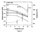
- the entrance pressure and temperature of the ultrasonic treatment zone 12 as a function of ultrasonic amplitude is shown in the graph of Figure 4 .
- the entrance pressure is substantially reduced as the ultrasonic amplitude is increased. This decrease of pressure is caused by the combined effect of the reduced viscosity of materials and reduction in friction of polymer melt along the die wall. It is also evident from Figure 4 that the pressure increases with increasing CNF concentration. It is interesting to note that the pressure increases slightly up to 15 wt% and increased significantly at 20 wt% CNF concentration. Such a behavior is apparently attributed to the percolation threshold occurring between 15 and 20 wt% CNF/PEI composites.
- Figure 4 also details the temperature at the ultrasonic treatment zone increasing with increasing ultrasonic amplitude.
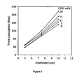
- the ultrasonic power consumption during ultrasonic treatment of PEI at various CNF concentrations as a function of ultrasonic amplitude is shown in Figure 5 .
- This set of data is obtained at 60 rpm.
- an increase of the power consumption was observed with an increase of amplitude.
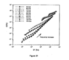
- Figure 6 shows the complex viscosity as a function of frequency for the untreated and ultrasonically treated CNF/PEI nanocomposites containing 0 to 20 wt% CNFs.
- the viscosities of CNF/PEI composites increase with increasing CNF content. Viscosity of ultrasonically treated composites is consistently higher compared to that of untreated ones.
- viscosity of virgin PEI slightly decreases with ultrasonic treatment.
- the viscosity of nanocomposites obtained at an amplitude of 10 ⁇ m shows slightly lower values than those at amplitudes of 5 ⁇ m and 7.5 ⁇ m. This is not only because of the thermomechanical degradation of polymer, but also because of a possible breakage of nanofibers during ultrasonic treatment.
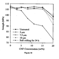
- Figure 8 shows the electrical volume resistivity of nanocomposites as a function of CNF concentration.
- the resistivity at 15 wt% of CNF loading dropped by about 2 orders of magnitude.
- a similar drop in the resistivity of nanocomposites extruded without ultrasonic treatment occurs at 17 wt% CNF loading.
- the volume resistivity is dependent not only on the fiber concentration, but also on the fiber length and their dispersion.
- ultrasonic treatment leads to an Improved dispersion of the CNFs.
- composites prepared by ball milling show percolation threshold at much lower CNF concentration (4 wt %). This is due the presence of long and aggregated fibers in these composites.
- thermo conductivity of untreated and ultrasonically treated CNF/PEI nanocomposites as a function of CNF content are presented in Figure 9 .
- the thermal conductivity of PEI/CNF nanocomposites increases from 0.23 to 0.52 W/mK as the CNF concentration increases from 5 wt% to 20 wt%.
- the thermal conductivity of CNFs is 20 W/mK, (as reported by Applied Sciences, Inc.) Although the thermal conductivity increases by more than two times with the addition of the CNFs, the prepared nanocomposites do not show a percolation threshold based on these measurements. This is due to the heat transport mainly occurring through the polymer matrix at the fiber concentrations presented.
- the thermal conductivity of 20 wt% CNF/PEI composites increases with increasing ultrasonic amplitude. This is the result of the continuously improved dispersion of CNFs by increasing ultrasonic power consumption.
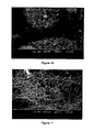
- Figure 10 shows SEM micrographs of CNFs as received and detail large aspect ratios (> 100).
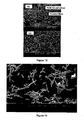
- the diameters of these nanofibers vary from 70 nm to 200 nm and sizes of their bundles range from 10 ⁇ m to 50 ⁇ m. After ball milling of CNFs with PEI powder, the bundles of CNFs remain. Interwoven bundles and aggregates of CNFs up to 50 ⁇ m in size were observed in SEM micrographs as shown in Figure 11 .
- Figure 12 depicts SEM micrographs of fractured surfaces of 15 wt% CNF/PEI nanocomposites without and with ultrasonic treatment at an amplitude of 10 ⁇ m.
- the CNFs are clustered in the matrix with about 2 ⁇ 5 ⁇ m diameter in untreated composites. In the treated nanocomposites CNFs are not clustered but still in contact with each other. The latter could be the reason why the percolation threshold is achieved at a lower concentration of about 15 wt% in ultrasonically treated nanocomposites.
- Figure 13 shows the SEM micrograph of CNFs extracted from the nanocomposite.
- the length of extracted CNFs is 2 ⁇ 10 ⁇ m which is lower than their initial length of 30-100 ⁇ m reported by Applied Sciences, Inc.
- the degradation of fiber length is attributed to the high shear in extruder and to the action of ultrasound.
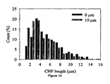
- Figure 14 shows the length distribution of CNFs in nanocomposites obtained without and with ultrasonic treatment, respectively, at a screw rotation speed of 60 rpm. Only a slight decrease in the fiber length due to ultrasonic treatment is observed.
- CNF/PEI nanocomposites with CNF contents up to 20 wt% have been prepared by means of a novel ultrasonic single screw compounding extruder. Based on rheological and electrical conductivity measurements, the estimated percolation threshold in ultrasonically treated CNF/PEI nanocomposites is found to be lower than those of untreated nanocomposites. Furthermore, it was established that high power ultrasound is effective in obtaining relatively homogeneous dispersion with improved electrical and thermal conductivity in the CNF/PEI nanocomposites. An increase of the Young's modulus in CNF/PEI nanocomposites was recorded under ultrasonic treatment, without reduction in the tensile strength. SEM micrographs of dry-mixed PEI/CNF composites by ball milling indicated the presence of CNF bundles. The CNF bundles are absent after compounding using an ultrasonic single screw extruder with ultrasonic treatment.
- Polyetherimide (PEI) in powder form made by GE plastics under trade name ULTEM 1000P was used as received.
- the multiwalled carbon nanotubes (MWNT) were provided by Nanostructured & Amorphous Materials, and were used as received.
- the MWNT had an outside diameter of 10-20 nm and length varied from 0.5 - 200 ⁇ m.
- the PEI powder was mixed with 1, 2, 5, and 10 wt% MWNT loading by ball milling for 24 hrs. The mixture was then dried for a minimum of 24 hrs at 110 °C in a vacuum oven prior to processing.
- a continuous co-rotating twin screw extruder 30 equipped with high power ultrasonic die 32 attachment was developed as shown in Figure 17 .
- Two horns 36 oscillating at a frequency of 40 kHz were attached to the die zone with a 4 mm gap size and molten compound was continuously subjected to amplitudes from 0-6.0 ⁇ m.
- the temperature in the barrel section was set from feed zone to die zone as 280°C, 340°C, 350°C, 360°C, 360°C.
- the screw 38 speed was set at 50 rpm and 0.5 lb/hr feed rate was used.
- Tensile bars according to ASTM D-638 were prepared using the HAAKE mini-jet piston injection molder at a temperature of 360°C and mold temperature of 130°C. The injection pressure was 740 bars in each case.
- Prepared nanocomposites were compression molded into discs of 25 mm diameter and 2.2 mm thickness at 300°C using the Carver 4122 compression molding press, for the rheological measurements.
- the samples for electrical conductivity measurement were also compression molded into discs of 90 mm diameter and 1 mm thickness.
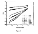
- the rheological properties of the nanocomposites were studied using an ARES, TA Instruments.
- a 25 mm parallel plate geometry in oscillatory shear mode with dynamic frequency sweep test was used at 340 °C for a fixed strain amplitude of 2%.
- a Keithley electrometer (Model 6517A) equipped with an 8009 test fixtures was used to measure the volume resistivity of the samples in accordance with the ASTM D257 method using applied voltage of 0.1V.
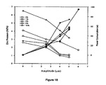
- Figure 18 shows the entrance die pressure and power consumption for various wt% loadings of CNT's as a function of ultrasonic amplitude.
- the measured pressure is before the ultrasonic treatment of PEI/MWNT composites.
- a continuous decrease in pressure with increasing ultrasonic amplitude was observed. This is from a combination of heating from dissipated energy from ultrasound, cavitational effect from ultrasonic waves leading to some thixotropic and permanent changes in polymer, reduction in friction at die walls and horn surfaces due to ultrasonic vibrations and possible shear thinning effect created by ultrasound waves.
- the die pressure increases with the increase of CNT loading.
- the measured power consumption is the total power consumption during the treatment of nanocomposites, a part of which is dissipated as heat whereas the rest is being utilized to disperse nanotubes in melt and increasing the polymer-nanotube interaction. It was observed that power consumption increased with the increase of ultrasound amplitude indicating more energy was transmitted from horns to polymer melt.
- the volume resistivity results of nanocomposites as a function of CNT's loading are plotted in Figure 23 .
- the volume resistivity decreased by 10 7 ⁇ -cm with 10 wt% loading.
- a sharp reduction in resistivity is observed between 1 and 2 wt% nanotubes content indicating the percolation threshold between 1 and 2 wt% nanotube loading.
- Figure 26 shows HRSEM micrographs of treated and untreated nanocomposites filled with 2wt% CNT's (note difference in relevant scale used). All images have clearly distinguished nanotubes that are randomly oriented and uniformly dispersed. The images show that the nanotubes were dispersed to a level of 50 nm diameter, which is close to the range (10-20nm) of as received CNTs. Not a single CNT bundle was observed for the treated samples.
- a new ultrasound assisted melt extrusion process was developed for manufacturing PEI/MWNT nanocomposites.
- the ultrasonically treated nanocomposites show significant changes in the rheological behavior with tremendous increase in the viscosity, storage modulus and reduced damping characteristics' of nanocomposites as compared to the untreated ones indicating the better dispersion of nanotubes.
- the Young's modulus and tensile strength increased without effecting elongation at break and yield strain of nanocomposites.
Claims (12)
- Verfahren zur Herstellung von Polymer-Verbundstoffen mit verbesserten Wärme- , elektrischen und/oder mechanischen Merkmalen, umfassend
das Bereitstellen eines oder mehrerer Polymere;
das Bereitstellen eines Füllstoffs, wobei der Füllstoff eine oder mehrere Nanofasern oder eine oder mehrere Nanoröhren ist;
das Bereitstellen eines Durchlaufmischers von einem Einzel- oder Doppelschneckenextruder zum Mischen des einen oder der mehreren Polymere und des Füllstoffs und ein Ultraschallbehandlungsmittel mit einer Ultraschallbehandlungszone mit einer Frequenz im Bereich von 154 kHz bis 1000 kHz, wobei der Durchlaufmischer zwei oder mehr Behandlungszonen aufweist, einschließlich der Ultraschallbehandlung, die in der zweiten Behandlungszone auftritt oder wobei der Durchlaufmischer wenigstens drei Behandlungszonen aufweist, wobei die Ultraschallbehandlung an der dritten Behandlungszone auftritt und wobei das Ultraschallbehandlungsmittel aus einer oder mehreren Ultraschallbehandlungs-Sonotroden besteht;
das Mischen im Durchlaufmischer des einen oder der mehreren Polymere und des Füllstoffs, um eine Polymer-/Füllstoffmischung zu erzeugen;
dadurch gekennzeichnet, dass das Verfahren weiterhin Folgendes umfasst:das Zuführen der Polymer-/Füllstoffmischung durch einen oder mehrere Stromlinienkanäle zur Ultraschallbehandlungszone durch einen Spalt zwischen der Extruderoberfläche und der Ultraschallbehandlungs-Sonotrode(n), wobei die Polymer/Füllstoffmischung weniger als 60 Sekunden lang einer Ultraschallbehandlung ausgesetzt wird, um somit den Füllstoff weiter zu dispergieren und einen Polymerverbundstoff mit verbesserten Wärme-, elektrischen und/oder mechanischen Merkmalen zu produzieren; unddas Zurückgewinnen der durch Ultraschall behandelten Polymer/Füllstoffmischung durch einen oder mehrere Stromlinien-Ausgangskanäle als ein Polymermischprodukt. - Verfahren nach Anspruch 1, wobei ein oder mehrere Polymere ein thermoplastischer Kunststoff und/oder ein warm gehärteter Kunststoff ist oder wobei das eine oder die mehreren Polymere ein thermoplastischer Gummi und/oder eine warm gehärtete reaktive Flüssigkeit ist oder wobei das eine oder die mehreren Polymere Polyetherimid ist.
- Verfahren nach Anspruch 1, wobei die eine oder mehreren Nanofasern eine Polymernanofaser, eine keramische Nanofaser und/oder eine Kohlenstoffnanofaser ist oder wobei die eine oder mehreren Nanoröhren eine Kohlenstoffnanoröhre ist.
- Verfahren nach Anspruch 1, wobei die eine oder mehreren Nanofasern einen Durchmesser von zwischen 1 Nanometer und 200 Nanometern aufweist oder wobei die eine oder mehreren Nanofasern einen Durchmesser von zwischen 15 Nanometern und 200 Nanometern aufweist.
- Verfahren nach Anspruch 1, wobei das Ultraschallbehandlungsmittel zu einer Frequenz von zwischen 15 kHz und 500 kHz ausgeführt wird oder wobei das Ultraschallbehandlungsmittel zu einer Temperatur von zwischen 30 °C und 400 °C ausgeführt wird.
- Verfahren nach Anspruch 1, wobei das Ultraschallbehandlungsmittel weniger als 30 Sekunden lang ausgeführt wird.
- Verfahren nach Anspruch 1, wobei die Ultraschallzone auftritt, nachdem die Verbindung aus einer Mischzone austritt und in eine mit Druck beaufschlagte Zone eintritt.
- Verfahren nach Anspruch 1, wobei die zwei oder mehr Behandlungszonen wenigstens eine Zone zum dispergierenden Mischen und wenigstens eine Zone zum verteilenden Mischen enthalten.
- Verfahren nach Anspruch 1, wobei eine oder mehrere Nanofasern eine Kohlenstoffnanofaser in einer Konzentration von zwischen 0 und 20 Gew.-% ist oder wobei das eine oder die mehreren Nanoröhren Kohlenstoffnanoröhren in einer Konzentration von zwischen 0 und 20 Gew.% sind.
- Verfahren nach Anspruch 1, wobei die mit Ultraschall behandelte Polymer/Füllstoffmischung anschließend mit Wasser abgekühlt wird.
- Verfahren nach Anspruch 1, wobei das Polymermischprodukt ein oder mehrere Granulate, ein oder mehrere Folien ist, einem Spritzblasmittel zugeführt wird oder einem Extrusionsmittel zugeführt wird.
- Apparat zum Mischen von Polymer und Füllstoff, umfassend:eine Ultraschallbehandlungszone, umfassend ein Ultraschallbehandlungsmittel bestehend aus einer oder mehreren Ultraschallbehandlungs-Sonotrode(n), die mit einer Frequenz von 15 kHz bis 1000 kHz arbeiten und derart ausgelegt sind, um eine Ultraschallverarbeitung der Polymer-/Füllstoffmischung von weniger als 60 Sekunden zu erlauben;ein Einzel- oder Doppelschneckenextruder; undein Austrittmittel, das zum Austreten der mit Ultraschall behandelten Mischung aus der Ultraschallbehandlungszone ausgelegt ist;dadurch gekennzeichnet, dass:der Einzel- oder Doppelschneckenextruder einen oder mehrere Stromlinienkanäle umfasst, die derart ausgelegt sind, um eine vorgemischte Mischung durch einen Spalt zwischen der Schneckenoberfläche und einer oder mehreren Ultraschallbehandlungs-Sonotrode(n) zur Ultraschallbehandlungszone abzugeben; unddas Austrittmittel für den Austritt der mit Ultraschall behandelten Mischung aus der Ultraschallbehandlungszone in einen oder mehrere Stromlinien-Austrittskanäle ausgelegt ist.
Applications Claiming Priority (3)
| Application Number | Priority Date | Filing Date | Title |
|---|---|---|---|
| US81090006P | 2006-06-05 | 2006-06-05 | |
| US92631307P | 2007-04-26 | 2007-04-26 | |
| PCT/US2007/013196 WO2007145918A2 (en) | 2006-06-05 | 2007-06-05 | Ultrasound assisted continuous process for dispersion of nanofibers and nanotubes in polymers |
Publications (3)
| Publication Number | Publication Date |
|---|---|
| EP2029265A2 EP2029265A2 (de) | 2009-03-04 |
| EP2029265A4 EP2029265A4 (de) | 2010-07-14 |
| EP2029265B1 true EP2029265B1 (de) | 2013-08-14 |
Family
ID=38832319
Family Applications (1)
| Application Number | Title | Priority Date | Filing Date |
|---|---|---|---|
| EP07795740.5A Not-in-force EP2029265B1 (de) | 2006-06-05 | 2007-06-05 | Ultraschallunterstütztes kontinuierliches Verfahren und Vorrichtung zur Dispersion von Nanofasern und Nanoröhrchen in Polymeren |
Country Status (4)
| Country | Link |
|---|---|
| US (1) | US20090275689A1 (de) |
| EP (1) | EP2029265B1 (de) |
| CA (1) | CA2658970C (de) |
| WO (1) | WO2007145918A2 (de) |
Families Citing this family (32)
| Publication number | Priority date | Publication date | Assignee | Title |
|---|---|---|---|---|
| US20100152325A1 (en) * | 2004-12-06 | 2010-06-17 | Avraam Isayev | Process for preparing polymer nanocomposites and nanocomposites prepared therefrom |
| MX2009003842A (es) * | 2009-04-08 | 2010-10-13 | Nanosoluciones S A De C V | Proceso continuo asistido por ultrasonido de frecuencia y amplitud variable, para la preparacion de nanocompuestos a base de polimeros y nanoparticulas. |
| RU2505400C2 (ru) * | 2011-04-12 | 2014-01-27 | Федеральное Казенное Предприятие "Авангард" | Двухканальная экструзионная головка для изготовления полимерного профильного полозка с применением ультразвуковых колебаний |
| KR20140026457A (ko) * | 2011-04-15 | 2014-03-05 | 더 유니버시티 오브 아크론 | 교차분리 및 탈황을 위한 초음파 혼들을 갖는 단일 및 트윈 스크류 압출기들 |
| RU2495887C1 (ru) * | 2012-02-27 | 2013-10-20 | Федеральное государственное унитарное предприятие "Ивановский научно-исследовательский институт плёночных материалов и искусственной кожи технического назначения" Федеральной службы безопасности Российской Федерации (ФГУП "ИвНИИПИК" ФСБ России) | Способ получения композита полимер/углеродные нанотрубки |
| US9620259B2 (en) | 2012-03-30 | 2017-04-11 | University Of Washington Through Its Center For Commercialization | Composites incorporated a conductive polymer nanofiber network |
| RU2500706C1 (ru) * | 2012-04-17 | 2013-12-10 | Федеральное государственное унитарное предприятие "Центральный аэрогидродинамический институт имени профессора Н.Е. Жуковского" (ФГУП "ЦАГИ") | Способ диспергирования наночастиц в эпоксидной смоле |
| GB201212487D0 (en) | 2012-07-13 | 2012-08-29 | Secr Defence | A device for measuring the hydration level of humans |
| WO2014032172A1 (en) | 2012-08-31 | 2014-03-06 | Soucy Techno Inc. | Rubber compositions and uses thereof |
| EP2909028B1 (de) | 2012-10-19 | 2019-09-25 | Rutgers, the State University of New Jersey | In-situ-peelingverfahren zur herstellung eines graphenverstärkten polymermatrixverbundstoffs |
| US11479652B2 (en) | 2012-10-19 | 2022-10-25 | Rutgers, The State University Of New Jersey | Covalent conjugates of graphene nanoparticles and polymer chains and composite materials formed therefrom |
| CA2909715C (en) | 2013-04-18 | 2022-05-24 | Rutgers, The State University Of New Jersey | In situ exfoliation method to fabricate a graphene-reinforced polymer matrix composite |
| CA2925928C (en) | 2013-10-18 | 2018-06-19 | Soucy Techno Inc. | Rubber compositions and uses thereof |
| US9663640B2 (en) | 2013-12-19 | 2017-05-30 | Soucy Techno Inc. | Rubber compositions and uses thereof |
| WO2015157433A1 (en) * | 2014-04-08 | 2015-10-15 | Applied Cavitation, Inc. | Systems and methods for producing materials suitable for additive manufacturing using a hydrodynamic cavitation apparatus |
| EP3174827B1 (de) | 2014-07-30 | 2022-04-20 | Rutgers, the State University of New Jersey | Graphenverstärkte polymermatrixverbundstoffe |
| CN111253618A (zh) * | 2015-03-17 | 2020-06-09 | 尼亚加拉装瓶有限责任公司 | 石墨烯增强的聚对苯二甲酸乙二醇酯 |
| JP6745288B2 (ja) * | 2015-03-17 | 2020-08-26 | ナイアガラ・ボトリング・リミテツド・ライアビリテイー・カンパニー | グラフェン強化ポリエチレンテレフタレート |
| JP6521701B2 (ja) * | 2015-03-31 | 2019-05-29 | ニッタ株式会社 | 複合素材の製造方法 |
| CA2992816A1 (en) * | 2015-07-08 | 2017-01-12 | Niagara Bottling, Llc | Graphene reinforced polyethylene terephthalate |
| AU2016289353B2 (en) | 2015-07-08 | 2020-05-28 | Sudheer BANDLA | Graphene reinforced polyethylene terephthalate |
| DE102016211912A1 (de) * | 2016-06-30 | 2018-01-04 | Robert Bosch Gmbh | Verfahren zum Aufbereiten eines Kunststoffs, Aufbereitungsvorrichtung und Steuergerät |
| US11702518B2 (en) | 2016-07-22 | 2023-07-18 | Rutgers, The State University Of New Jersey | In situ bonding of carbon fibers and nanotubes to polymer matrices |
| US11059945B2 (en) | 2016-07-22 | 2021-07-13 | Rutgers, The State University Of New Jersey | In situ bonding of carbon fibers and nanotubes to polymer matrices |
| US11673352B2 (en) * | 2016-09-20 | 2023-06-13 | United States Of America As Represented By The Administrator Of Nasa | Automated wave guide system for in-process monitoring of carbon fiber reinforced polymer (CFRP) composite laminates with hanning window tone-bursts of center frequencies from 100-225 kHz and 100-350 kHz |
| RU2645007C1 (ru) * | 2016-11-11 | 2018-02-15 | Общество с ограниченной ответственностью "Углерод Чг" | Способ получения композитного материала |
| WO2019143662A1 (en) | 2018-01-16 | 2019-07-25 | Rutgers The State University Of New Jersey | Use of graphene-polymer composites to improve barrier resistance of polymers to liquid and gas permeants |
| ES2965540T3 (es) * | 2018-07-30 | 2024-04-15 | Fund Eurecat | Dispositivo ultrasónico para máquina extrusora de polímeros |
| DE202018106258U1 (de) | 2018-10-15 | 2020-01-20 | Rutgers, The State University Of New Jersey | Nano-Graphitische Schwämme |
| US11807757B2 (en) | 2019-05-07 | 2023-11-07 | Rutgers, The State University Of New Jersey | Economical multi-scale reinforced composites |
| WO2021079194A2 (en) * | 2019-10-24 | 2021-04-29 | Tianjin Laird Technologies Limited | Dispensing systems and methods including online remixing of thermal management and/or emi mitigation materials |
| CN114307791B (zh) * | 2021-12-31 | 2023-02-24 | 无锡东恒新能源科技有限公司 | 一种碳纳米管的分散系统 |
Family Cites Families (5)
| Publication number | Priority date | Publication date | Assignee | Title |
|---|---|---|---|---|
| US6528554B1 (en) * | 2001-02-15 | 2003-03-04 | The University Of Akron | Ultrasound assisted continuous process for making polymer blends and copolymers |
| US6783702B2 (en) * | 2001-07-11 | 2004-08-31 | Hyperion Catalysis International, Inc. | Polyvinylidene fluoride composites and methods for preparing same |
| MY137957A (en) * | 2003-07-16 | 2009-04-30 | Idemitsu Kosan Co | Apparatus of applying ultrasonic vibration to resin material, method of kneading, compounding and blending resin material by use of the ultrasonic vibration applying apparatus, and resin composition |
| US7309727B2 (en) * | 2003-09-29 | 2007-12-18 | General Electric Company | Conductive thermoplastic compositions, methods of manufacture and articles derived from such compositions |
| US7296576B2 (en) * | 2004-08-18 | 2007-11-20 | Zyvex Performance Materials, Llc | Polymers for enhanced solubility of nanomaterials, compositions and methods therefor |
-
2007
- 2007-06-05 EP EP07795740.5A patent/EP2029265B1/de not_active Not-in-force
- 2007-06-05 WO PCT/US2007/013196 patent/WO2007145918A2/en active Application Filing
- 2007-06-05 CA CA2658970A patent/CA2658970C/en not_active Expired - Fee Related
- 2007-06-05 US US12/303,377 patent/US20090275689A1/en not_active Abandoned
Also Published As
| Publication number | Publication date |
|---|---|
| CA2658970A1 (en) | 2007-12-21 |
| WO2007145918A3 (en) | 2008-01-24 |
| CA2658970C (en) | 2014-10-21 |
| EP2029265A2 (de) | 2009-03-04 |
| EP2029265A4 (de) | 2010-07-14 |
| WO2007145918A2 (en) | 2007-12-21 |
| US20090275689A1 (en) | 2009-11-05 |
Similar Documents
| Publication | Publication Date | Title |
|---|---|---|
| EP2029265B1 (de) | Ultraschallunterstütztes kontinuierliches Verfahren und Vorrichtung zur Dispersion von Nanofasern und Nanoröhrchen in Polymeren | |
| Isayev et al. | Ultrasound assisted twin screw extrusion of polymer–nanocomposites containing carbon nanotubes | |
| Jin et al. | A review of the preparation and properties of carbon nanotubes-reinforced polymer compositess | |
| JP4896422B2 (ja) | 微細炭素繊維含有樹脂組成物の製造方法 | |
| Al-Saleh et al. | Review of the mechanical properties of carbon nanofiber/polymer composites | |
| KR100810977B1 (ko) | 중합체 매트릭스에 매립된 배향된 나노섬유 | |
| Jimenez et al. | Electrically conductive polymer nanocomposites of polymethylmethacrylate and carbon nanofibers prepared by chaotic mixing | |
| KR101157451B1 (ko) | 전도성이 향상된 고분자-탄소나노튜브 복합체 제조방법 | |
| JP2020521864A (ja) | 超臨界流体を使用してポリマー母材中に黒鉛材料を剥離し分散させる方法 | |
| Doagou-Rad et al. | Influence of processing conditions on the mechanical behavior of MWCNT reinforced thermoplastic nanocomposites | |
| JP4869615B2 (ja) | 微細炭素繊維含有樹脂組成物の製造方法 | |
| Kenig | Processing of polymer nanocomposites | |
| Ávila-Orta et al. | Ultrasound-assisted melt extrusion of polymer nanocomposites | |
| KR20190034581A (ko) | 탄소 섬유 및 나노튜브의 폴리머에 원위치(in situ) 결합 | |
| Mathur et al. | Properties of PMMA/carbon nanotubes nanocomposites | |
| Kim et al. | Synergistic mechanical reinforcement of woven carbon fiber/polypropylene composites using plasma treatment and nanoclay | |
| CN111073040A (zh) | 一种HGM-CNTs键合物的制备方法及轻质抗静电聚丙烯材料 | |
| JP4404702B2 (ja) | カーボンナノ線条体分散樹脂組成物の製造方法 | |
| Mazlan et al. | Effects of different processing techniques on multi-walled carbon nanotubes/silicone rubber nanocomposite on tensile strength properties | |
| Isayev et al. | Ultrasound assisted single screw extrusion process for dispersion of carbon nanofibers in polymers | |
| Arigbabowo et al. | Fused filament fabrication of polyamide 6 nanographene composite for electrostatic discharge applications | |
| Hosur et al. | Rheology, flexure and thermomechanical characterization of epoxy/CNF nanocomposites: Effect of dispersion techniques | |
| US11702518B2 (en) | In situ bonding of carbon fibers and nanotubes to polymer matrices | |
| Park et al. | Surface modification of carbon nanotubes for high-performance polymer composites | |
| Weisenberger et al. | Carbon nanotube polymer composites: recent developments in mechanical properties |
Legal Events
| Date | Code | Title | Description |
|---|---|---|---|
| PUAI | Public reference made under article 153(3) epc to a published international application that has entered the european phase |
Free format text: ORIGINAL CODE: 0009012 |
|
| 17P | Request for examination filed |
Effective date: 20090102 |
|
| AK | Designated contracting states |
Kind code of ref document: A2 Designated state(s): AT BE BG CH CY CZ DE DK EE ES FI FR GB GR HU IE IS IT LI LT LU LV MC MT NL PL PT RO SE SI SK TR |
|
| AX | Request for extension of the european patent |
Extension state: AL BA HR MK RS |
|
| DAX | Request for extension of the european patent (deleted) | ||
| A4 | Supplementary search report drawn up and despatched |
Effective date: 20100616 |
|
| 17Q | First examination report despatched |
Effective date: 20110909 |
|
| REG | Reference to a national code |
Ref country code: DE Ref legal event code: R079 Ref document number: 602007032268 Country of ref document: DE Free format text: PREVIOUS MAIN CLASS: B01F0011000000 Ipc: B29B0007360000 |
|
| GRAP | Despatch of communication of intention to grant a patent |
Free format text: ORIGINAL CODE: EPIDOSNIGR1 |
|
| RIC1 | Information provided on ipc code assigned before grant |
Ipc: B29B 7/42 20060101ALI20130215BHEP Ipc: B29B 7/90 20060101ALI20130215BHEP Ipc: B29B 7/36 20060101AFI20130215BHEP |
|
| GRAS | Grant fee paid |
Free format text: ORIGINAL CODE: EPIDOSNIGR3 |
|
| GRAA | (expected) grant |
Free format text: ORIGINAL CODE: 0009210 |
|
| AK | Designated contracting states |
Kind code of ref document: B1 Designated state(s): AT BE BG CH CY CZ DE DK EE ES FI FR GB GR HU IE IS IT LI LT LU LV MC MT NL PL PT RO SE SI SK TR |
|
| REG | Reference to a national code |
Ref country code: GB Ref legal event code: FG4D |
|
| REG | Reference to a national code |
Ref country code: AT Ref legal event code: REF Ref document number: 626528 Country of ref document: AT Kind code of ref document: T Effective date: 20130815 Ref country code: CH Ref legal event code: EP |
|
| REG | Reference to a national code |
Ref country code: IE Ref legal event code: FG4D |
|
| REG | Reference to a national code |
Ref country code: DE Ref legal event code: R096 Ref document number: 602007032268 Country of ref document: DE Effective date: 20131010 |
|
| REG | Reference to a national code |
Ref country code: AT Ref legal event code: MK05 Ref document number: 626528 Country of ref document: AT Kind code of ref document: T Effective date: 20130814 Ref country code: NL Ref legal event code: VDEP Effective date: 20130814 |
|
| REG | Reference to a national code |
Ref country code: LT Ref legal event code: MG4D |
|
| PG25 | Lapsed in a contracting state [announced via postgrant information from national office to epo] |
Ref country code: LT Free format text: LAPSE BECAUSE OF FAILURE TO SUBMIT A TRANSLATION OF THE DESCRIPTION OR TO PAY THE FEE WITHIN THE PRESCRIBED TIME-LIMIT Effective date: 20130814 Ref country code: IS Free format text: LAPSE BECAUSE OF FAILURE TO SUBMIT A TRANSLATION OF THE DESCRIPTION OR TO PAY THE FEE WITHIN THE PRESCRIBED TIME-LIMIT Effective date: 20131214 Ref country code: PT Free format text: LAPSE BECAUSE OF FAILURE TO SUBMIT A TRANSLATION OF THE DESCRIPTION OR TO PAY THE FEE WITHIN THE PRESCRIBED TIME-LIMIT Effective date: 20131216 Ref country code: CY Free format text: LAPSE BECAUSE OF FAILURE TO SUBMIT A TRANSLATION OF THE DESCRIPTION OR TO PAY THE FEE WITHIN THE PRESCRIBED TIME-LIMIT Effective date: 20130724 Ref country code: SE Free format text: LAPSE BECAUSE OF FAILURE TO SUBMIT A TRANSLATION OF THE DESCRIPTION OR TO PAY THE FEE WITHIN THE PRESCRIBED TIME-LIMIT Effective date: 20130814 Ref country code: AT Free format text: LAPSE BECAUSE OF FAILURE TO SUBMIT A TRANSLATION OF THE DESCRIPTION OR TO PAY THE FEE WITHIN THE PRESCRIBED TIME-LIMIT Effective date: 20130814 |
|
| PG25 | Lapsed in a contracting state [announced via postgrant information from national office to epo] |
Ref country code: SI Free format text: LAPSE BECAUSE OF FAILURE TO SUBMIT A TRANSLATION OF THE DESCRIPTION OR TO PAY THE FEE WITHIN THE PRESCRIBED TIME-LIMIT Effective date: 20130814 Ref country code: PL Free format text: LAPSE BECAUSE OF FAILURE TO SUBMIT A TRANSLATION OF THE DESCRIPTION OR TO PAY THE FEE WITHIN THE PRESCRIBED TIME-LIMIT Effective date: 20130814 Ref country code: FI Free format text: LAPSE BECAUSE OF FAILURE TO SUBMIT A TRANSLATION OF THE DESCRIPTION OR TO PAY THE FEE WITHIN THE PRESCRIBED TIME-LIMIT Effective date: 20130814 Ref country code: BE Free format text: LAPSE BECAUSE OF FAILURE TO SUBMIT A TRANSLATION OF THE DESCRIPTION OR TO PAY THE FEE WITHIN THE PRESCRIBED TIME-LIMIT Effective date: 20130814 Ref country code: LV Free format text: LAPSE BECAUSE OF FAILURE TO SUBMIT A TRANSLATION OF THE DESCRIPTION OR TO PAY THE FEE WITHIN THE PRESCRIBED TIME-LIMIT Effective date: 20130814 Ref country code: GR Free format text: LAPSE BECAUSE OF FAILURE TO SUBMIT A TRANSLATION OF THE DESCRIPTION OR TO PAY THE FEE WITHIN THE PRESCRIBED TIME-LIMIT Effective date: 20131115 |
|
| PG25 | Lapsed in a contracting state [announced via postgrant information from national office to epo] |
Ref country code: CY Free format text: LAPSE BECAUSE OF FAILURE TO SUBMIT A TRANSLATION OF THE DESCRIPTION OR TO PAY THE FEE WITHIN THE PRESCRIBED TIME-LIMIT Effective date: 20130814 |
|
| PG25 | Lapsed in a contracting state [announced via postgrant information from national office to epo] |
Ref country code: RO Free format text: LAPSE BECAUSE OF FAILURE TO SUBMIT A TRANSLATION OF THE DESCRIPTION OR TO PAY THE FEE WITHIN THE PRESCRIBED TIME-LIMIT Effective date: 20130814 Ref country code: DK Free format text: LAPSE BECAUSE OF FAILURE TO SUBMIT A TRANSLATION OF THE DESCRIPTION OR TO PAY THE FEE WITHIN THE PRESCRIBED TIME-LIMIT Effective date: 20130814 Ref country code: EE Free format text: LAPSE BECAUSE OF FAILURE TO SUBMIT A TRANSLATION OF THE DESCRIPTION OR TO PAY THE FEE WITHIN THE PRESCRIBED TIME-LIMIT Effective date: 20130814 Ref country code: CZ Free format text: LAPSE BECAUSE OF FAILURE TO SUBMIT A TRANSLATION OF THE DESCRIPTION OR TO PAY THE FEE WITHIN THE PRESCRIBED TIME-LIMIT Effective date: 20130814 Ref country code: SK Free format text: LAPSE BECAUSE OF FAILURE TO SUBMIT A TRANSLATION OF THE DESCRIPTION OR TO PAY THE FEE WITHIN THE PRESCRIBED TIME-LIMIT Effective date: 20130814 Ref country code: NL Free format text: LAPSE BECAUSE OF FAILURE TO SUBMIT A TRANSLATION OF THE DESCRIPTION OR TO PAY THE FEE WITHIN THE PRESCRIBED TIME-LIMIT Effective date: 20130814 |
|
| PG25 | Lapsed in a contracting state [announced via postgrant information from national office to epo] |
Ref country code: IT Free format text: LAPSE BECAUSE OF FAILURE TO SUBMIT A TRANSLATION OF THE DESCRIPTION OR TO PAY THE FEE WITHIN THE PRESCRIBED TIME-LIMIT Effective date: 20130814 Ref country code: ES Free format text: LAPSE BECAUSE OF FAILURE TO SUBMIT A TRANSLATION OF THE DESCRIPTION OR TO PAY THE FEE WITHIN THE PRESCRIBED TIME-LIMIT Effective date: 20130814 |
|
| PLBE | No opposition filed within time limit |
Free format text: ORIGINAL CODE: 0009261 |
|
| STAA | Information on the status of an ep patent application or granted ep patent |
Free format text: STATUS: NO OPPOSITION FILED WITHIN TIME LIMIT |
|
| 26N | No opposition filed |
Effective date: 20140515 |
|
| REG | Reference to a national code |
Ref country code: DE Ref legal event code: R097 Ref document number: 602007032268 Country of ref document: DE Effective date: 20140515 |
|
| PG25 | Lapsed in a contracting state [announced via postgrant information from national office to epo] |
Ref country code: LU Free format text: LAPSE BECAUSE OF FAILURE TO SUBMIT A TRANSLATION OF THE DESCRIPTION OR TO PAY THE FEE WITHIN THE PRESCRIBED TIME-LIMIT Effective date: 20140605 Ref country code: MC Free format text: LAPSE BECAUSE OF FAILURE TO SUBMIT A TRANSLATION OF THE DESCRIPTION OR TO PAY THE FEE WITHIN THE PRESCRIBED TIME-LIMIT Effective date: 20130814 |
|
| REG | Reference to a national code |
Ref country code: CH Ref legal event code: PL |
|
| GBPC | Gb: european patent ceased through non-payment of renewal fee |
Effective date: 20140605 |
|
| REG | Reference to a national code |
Ref country code: IE Ref legal event code: MM4A |
|
| PG25 | Lapsed in a contracting state [announced via postgrant information from national office to epo] |
Ref country code: CH Free format text: LAPSE BECAUSE OF NON-PAYMENT OF DUE FEES Effective date: 20140630 Ref country code: IE Free format text: LAPSE BECAUSE OF NON-PAYMENT OF DUE FEES Effective date: 20140605 Ref country code: LI Free format text: LAPSE BECAUSE OF NON-PAYMENT OF DUE FEES Effective date: 20140630 |
|
| PG25 | Lapsed in a contracting state [announced via postgrant information from national office to epo] |
Ref country code: GB Free format text: LAPSE BECAUSE OF NON-PAYMENT OF DUE FEES Effective date: 20140605 |
|
| REG | Reference to a national code |
Ref country code: FR Ref legal event code: PLFP Year of fee payment: 9 |
|
| PGFP | Annual fee paid to national office [announced via postgrant information from national office to epo] |
Ref country code: FR Payment date: 20150623 Year of fee payment: 9 |
|
| PGFP | Annual fee paid to national office [announced via postgrant information from national office to epo] |
Ref country code: DE Payment date: 20150824 Year of fee payment: 9 |
|
| PG25 | Lapsed in a contracting state [announced via postgrant information from national office to epo] |
Ref country code: MT Free format text: LAPSE BECAUSE OF FAILURE TO SUBMIT A TRANSLATION OF THE DESCRIPTION OR TO PAY THE FEE WITHIN THE PRESCRIBED TIME-LIMIT Effective date: 20130814 |
|
| PG25 | Lapsed in a contracting state [announced via postgrant information from national office to epo] |
Ref country code: BG Free format text: LAPSE BECAUSE OF FAILURE TO SUBMIT A TRANSLATION OF THE DESCRIPTION OR TO PAY THE FEE WITHIN THE PRESCRIBED TIME-LIMIT Effective date: 20130814 |
|
| PG25 | Lapsed in a contracting state [announced via postgrant information from national office to epo] |
Ref country code: HU Free format text: LAPSE BECAUSE OF FAILURE TO SUBMIT A TRANSLATION OF THE DESCRIPTION OR TO PAY THE FEE WITHIN THE PRESCRIBED TIME-LIMIT; INVALID AB INITIO Effective date: 20070605 Ref country code: TR Free format text: LAPSE BECAUSE OF FAILURE TO SUBMIT A TRANSLATION OF THE DESCRIPTION OR TO PAY THE FEE WITHIN THE PRESCRIBED TIME-LIMIT Effective date: 20130814 |
|
| REG | Reference to a national code |
Ref country code: DE Ref legal event code: R119 Ref document number: 602007032268 Country of ref document: DE |
|
| REG | Reference to a national code |
Ref country code: FR Ref legal event code: ST Effective date: 20170228 |
|
| PG25 | Lapsed in a contracting state [announced via postgrant information from national office to epo] |
Ref country code: DE Free format text: LAPSE BECAUSE OF NON-PAYMENT OF DUE FEES Effective date: 20170103 Ref country code: FR Free format text: LAPSE BECAUSE OF NON-PAYMENT OF DUE FEES Effective date: 20160630 |