EP2026603A2 - Hörvorrichtung mit linearem Schalter - Google Patents
Hörvorrichtung mit linearem Schalter Download PDFInfo
- Publication number
- EP2026603A2 EP2026603A2 EP08104474A EP08104474A EP2026603A2 EP 2026603 A2 EP2026603 A2 EP 2026603A2 EP 08104474 A EP08104474 A EP 08104474A EP 08104474 A EP08104474 A EP 08104474A EP 2026603 A2 EP2026603 A2 EP 2026603A2
- Authority
- EP
- European Patent Office
- Prior art keywords
- battery
- actuating element
- contact
- contact element
- hearing
- Prior art date
- Legal status (The legal status is an assumption and is not a legal conclusion. Google has not performed a legal analysis and makes no representation as to the accuracy of the status listed.)
- Withdrawn
Links
Images



Classifications
-
- H—ELECTRICITY
- H04—ELECTRIC COMMUNICATION TECHNIQUE
- H04R—LOUDSPEAKERS, MICROPHONES, GRAMOPHONE PICK-UPS OR LIKE ACOUSTIC ELECTROMECHANICAL TRANSDUCERS; ELECTRIC HEARING AIDS; PUBLIC ADDRESS SYSTEMS
- H04R25/00—Electric hearing aids
- H04R25/60—Mounting or interconnection of hearing aid parts, e.g. inside tips, housings or to ossicles
- H04R25/602—Mounting or interconnection of hearing aid parts, e.g. inside tips, housings or to ossicles of batteries
-
- H—ELECTRICITY
- H01—ELECTRIC ELEMENTS
- H01M—PROCESSES OR MEANS, e.g. BATTERIES, FOR THE DIRECT CONVERSION OF CHEMICAL ENERGY INTO ELECTRICAL ENERGY
- H01M50/00—Constructional details or processes of manufacture of the non-active parts of electrochemical cells other than fuel cells, e.g. hybrid cells
- H01M50/20—Mountings; Secondary casings or frames; Racks, modules or packs; Suspension devices; Shock absorbers; Transport or carrying devices; Holders
- H01M50/204—Racks, modules or packs for multiple batteries or multiple cells
- H01M50/207—Racks, modules or packs for multiple batteries or multiple cells characterised by their shape
- H01M50/216—Racks, modules or packs for multiple batteries or multiple cells characterised by their shape adapted for button or coin cells
-
- H—ELECTRICITY
- H04—ELECTRIC COMMUNICATION TECHNIQUE
- H04R—LOUDSPEAKERS, MICROPHONES, GRAMOPHONE PICK-UPS OR LIKE ACOUSTIC ELECTROMECHANICAL TRANSDUCERS; ELECTRIC HEARING AIDS; PUBLIC ADDRESS SYSTEMS
- H04R2225/00—Details of deaf aids covered by H04R25/00, not provided for in any of its subgroups
- H04R2225/61—Aspects relating to mechanical or electronic switches or control elements, e.g. functioning
-
- H—ELECTRICITY
- H04—ELECTRIC COMMUNICATION TECHNIQUE
- H04R—LOUDSPEAKERS, MICROPHONES, GRAMOPHONE PICK-UPS OR LIKE ACOUSTIC ELECTROMECHANICAL TRANSDUCERS; ELECTRIC HEARING AIDS; PUBLIC ADDRESS SYSTEMS
- H04R25/00—Electric hearing aids
- H04R25/60—Mounting or interconnection of hearing aid parts, e.g. inside tips, housings or to ossicles
- H04R25/603—Mounting or interconnection of hearing aid parts, e.g. inside tips, housings or to ossicles of mechanical or electronic switches or control elements
-
- Y—GENERAL TAGGING OF NEW TECHNOLOGICAL DEVELOPMENTS; GENERAL TAGGING OF CROSS-SECTIONAL TECHNOLOGIES SPANNING OVER SEVERAL SECTIONS OF THE IPC; TECHNICAL SUBJECTS COVERED BY FORMER USPC CROSS-REFERENCE ART COLLECTIONS [XRACs] AND DIGESTS
- Y02—TECHNOLOGIES OR APPLICATIONS FOR MITIGATION OR ADAPTATION AGAINST CLIMATE CHANGE
- Y02E—REDUCTION OF GREENHOUSE GAS [GHG] EMISSIONS, RELATED TO ENERGY GENERATION, TRANSMISSION OR DISTRIBUTION
- Y02E60/00—Enabling technologies; Technologies with a potential or indirect contribution to GHG emissions mitigation
- Y02E60/10—Energy storage using batteries
Definitions
- the present invention relates to a hearing device with a battery compartment for receiving a battery, an actuating element for switching on and / or off the hearing device, which is arranged on the battery compartment and a contact element having a contact point, and in a first position of the actuating element on the Contact point picks up an electrical potential on the battery.
- hearing device is understood in particular to mean a hearing device.
- the term includes other portable and non-portable acoustic devices such as headsets, headphones and the like.
- Hearing aids are portable hearing aids that are used to care for the hearing impaired.
- different types of hearing aids such as behind-the-ear hearing aids (BTE), hearing aid with external receiver (RIC: receiver in the canal) and in-the-ear hearing aids (IDO), e.g. Concha hearing aids or canal hearing aids (ITE, CIC).
- BTE behind-the-ear hearing aids
- RIC hearing aid with external receiver
- IDO in-the-ear hearing aids
- ITE canal hearing aids
- the hearing aids listed by way of example are worn on the outer ear or in the ear canal.
- bone conduction hearing aids, implantable or vibrotactile hearing aids are also available on the market. The stimulation of the damaged hearing takes place either mechanically or electrically.
- Hearing aids have in principle as essential components an input transducer, an amplifier and an output transducer.
- the input transducer is usually a sound receiver, z. As a microphone, and / or an electromagnetic receiver, for. B. an induction coil.
- the output transducer is usually used as an electroacoustic transducer, z. As miniature speaker, or as an electromechanical transducer, z. B. bone conduction, realized.
- the amplifier is usually integrated in a signal processing unit. This basic structure is in FIG. 1 shown using the example of a behind-the-ear hearing aid. In a hearing aid housing 1 for carrying behind the ear, one or more microphones 2 for receiving the sound from the environment are installed.
- a signal processing unit 3 which is also integrated in the hearing aid housing 1, processes the microphone signals and amplifies them.
- the output signal of the signal processing unit 3 is transmitted to a loudspeaker or earpiece 4, which outputs an acoustic signal.
- the sound is optionally transmitted via a sound tube, which is fixed with an earmold in the ear canal, to the eardrum of the device carrier.
- the power supply of the hearing device and in particular of the signal processing unit 3 is carried out by a likewise integrated into the hearing aid housing 1 battery. 5
- Hearing aids usually have a switch and can therefore be switched on or off at any time.
- a hearing aid with a battery compartment and a switch is known, wherein it is essential that the switch is designed as a rotary ring having an actuating element, by means of which the rotary ring for turning on and off of the hearing aid is rotatable.
- the battery is removed from a contact element and the circuit is interrupted.
- the actuating element protrudes less from the actuating element when rotating the rotary ring, in particular in the end positions, so that the tangible surface of the actuating element becomes smaller.
- the document discloses US 4,230,777 a switch for a communication device, with a knob which is adapted to receive a battery.
- the knob is a housing for the battery, so that Turning the knob also turns the battery on.
- the switch further comprises two contact elements which rest on a lid of the rotary knob.
- the lid of the knob also has two openings into which the contact elements protrude as soon as the knob is rotated accordingly. In this way, a circuit is closed and the device is turned on.
- the disadvantage is that the two contact elements constantly touch the lid of the knob, which can lead by turning the knob to a rubbing off the material of the lid and thus by the abraded chips to break the circuit.
- there is still the problem that the tangible surface of the knob is not fully accessible.
- the object of the present invention is thus to enable reliable switching on and off of a hearing device.
- a hearing device with a battery compartment for receiving a battery, an actuating element for switching on and / or off the hearing, which is arranged on the battery compartment and a contact element having a contact point, and in a first position of the actuating element via the contact point picks up an electrical potential on the battery, wherein the actuating element lifts in a relation to the first position linearly shifted second position the contact element at a different from the contact point Abhebeabpeaks the contact element to lift the contact point of the contact element of the battery.
- the contact point of the contact element only touches the battery and no other substances, because the contact element is not lifted directly at the contact point.
- the contact point of the contact element remains unaffected by the actuating element, which increases the reliability of the electrical contact with the battery.
- the linear Movement of the actuating element ensures that the graspable surface of the actuating element always remains the same, so that the actuating element can be grasped particularly comfortably by a user.
- Another advantage is that the battery compartment itself is freed from complicated mechanics, which has an effect on the robustness of the hearing device.
- the lift-off of the contact element has a run-on slope at which the actuating element lifts off the contact element, and wherein the run-on slope is formed such that a movement of the actuating element from the first to the second position causes a substantially perpendicular movement of the contact element.
- the contact element can be lifted particularly reliable and removed from the battery. With a run-on slope is achieved that the actuator can lift off the contact element directly on the run-on slope only by a linear displacement.
- the actuating element lifts off the contact element from the battery by means of a lever arm which is designed such that a movement of the actuating element from the first to the second position brings about a movement of the contact element substantially parallel thereto.
- the contact element can be arranged at a greater distance from the actuating element, which has a certain freedom in arranging the fastening element to the hearing device result.
- the actuating element has a latching nose, which projects into at least one position of the actuating element in a recess of a housing or a frame of the hearing to the actuator stable to keep.
- the locking lug With the locking lug, a robust construction is achieved and, moreover, it is ensured that, when the actuating element is moved, the intrusion of the locking lug into an opening indicates a predetermined state of the hearing device.
- the actuating element has a recess and the housing or the frame has a corresponding latching lug.
- FIG. 2 illustrated behind-the-ear hearing aid is an outstanding from a housing 1 actuator 10 for switching on and off of the hearing aid is provided.
- the actuator 10 is disposed on a battery compartment 19 of the hearing aid.
- the actuating element 10 has a sliding plate 11, which in a Section 18 of a frame 17 is added. Thus, the actuator 10 can be moved along the cutout 18.
- the actuating element 10 comprises a cuboid Abhebeelement 12, which is arranged on the sliding plate 11 on a side opposite the actuating element 10 side of the slide plate 11. The essential here is that the actuating element 10 protrudes from the frame 17 and thus from the housing 1 of the hearing aid, and that the linear displacement of the actuating element 10 along the cutout 18 has no influence on the tangible surface of the actuating element 10.
- a battery 5 Like also in FIG. 3 is shown in the battery compartment 19 is a battery 5.
- a contact element 14 which picks up there an electrical potential.
- a circuit is closed and the hearing aid is turned on.
- the contact element 14 contacts the battery 5 only via a contact point 20, which is arranged at one end of the contact element 14.
- the contact element 14 has a run-on slope 15, on which the contact element 14 can be lifted off and removed from the battery.
- the contact point 20 is clearly spaced from the run-up slope 15.
- the contact element 14 when the contact element 14 is not lifted directly by the lifting element 12, but by means of a lever arm which can be arranged substantially parallel to the sliding plate 11, and For example, if the contact element is arranged perpendicular to the cutout 18, the linear displacement of the actuating element 10 along the cutout 18 can result in a movement of the contact element which is also parallel to the cutout 18.
- the first position of the actuating element 10 is shown. It can be seen even more clearly here that the electrical potential at the gripping surface 13 of the battery 5 is picked up by the contact element 14 only via the contact point 20.
- the contact element 14 is lifted by the Abhebelelement 12 at the run-on slope 15 and thus the contact point 20 of the contact element 14 away from the battery. Because the contact point 20 of the contact element 14 can only touch the Abgreif Solutions 13 of the battery 5 and no other substances, this scrape material is avoided and the contact point 20 always remains in contact.
- the sliding plate 11 of in FIG. 7 reproduced actuator 10 has a latching lug 16 which projects in the first and second position of the actuating element 10 in each case a recess in the frame or housing of the hearing aid.
Landscapes
- Chemical & Material Sciences (AREA)
- Chemical Kinetics & Catalysis (AREA)
- Electrochemistry (AREA)
- General Chemical & Material Sciences (AREA)
- Health & Medical Sciences (AREA)
- General Health & Medical Sciences (AREA)
- Neurosurgery (AREA)
- Otolaryngology (AREA)
- Physics & Mathematics (AREA)
- Engineering & Computer Science (AREA)
- Acoustics & Sound (AREA)
- Signal Processing (AREA)
- Battery Mounting, Suspending (AREA)
- Slide Switches (AREA)
Abstract
Description
- Die vorliegende Erfindung betrifft eine Hörvorrichtung mit einem Batteriefach zur Aufnahme einer Batterie, einem Betätigungselement zum Einschalten und/oder Ausschalten der Hörvorrichtung, das an dem Batteriefach angeordnet ist und einem Kontaktelement, das eine Kontaktstelle aufweist, und das in einer ersten Stellung des Betätigungselements über die Kontaktstelle ein elektrisches Potential an der Batterie abgreift. Unter dem Begriff Hörvorrichtung wird hier insbesondere ein Hörgerät verstanden. Darüber hinaus fallen unter den Begriff aber auch andere tragbare und nicht tragbare akustische Geräte wie Headsets, Kopfhörer und dergleichen.
- Hörgeräte sind tragbare Hörvorrichtungen, die zur Versorgung von Schwerhörenden dienen. Um den zahlreichen individuellen Bedürfnissen entgegenzukommen, werden unterschiedliche Bauformen von Hörgeräten wie Hinter-dem-Ohr-Hörgeräte (HdO), Hörgerät mit externem Hörer (RIC: receiver in the canal) und In-dem-Ohr-Hörgeräte (IdO), z.B. auch Concha-Hörgeräte oder Kanal-Hörgeräte (ITE, CIC), bereitgestellt. Die beispielhaft aufgeführten Hörgeräte werden am Außenohr oder im Gehörgang getragen. Darüber hinaus stehen auf dem Markt aber auch Knochenleitungshörhilfen, implantierbare oder vibrotaktile Hörhilfen zur Verfügung. Dabei erfolgt die Stimulation des geschädigten Gehörs entweder mechanisch oder elektrisch.
- Hörgeräte besitzen prinzipiell als wesentliche Komponenten einen Eingangswandler, einen Verstärker und einen Ausgangswandler. Der Eingangswandler ist in der Regel ein Schallempfänger, z. B. ein Mikrofon, und/oder ein elektromagnetischer Empfänger, z. B. eine Induktionsspule. Der Ausgangswandler ist meist als elektroakustischer Wandler, z. B. Miniaturlautsprecher, oder als elektromechanischer Wandler, z. B. Knochenleitungshörer, realisiert. Der Verstärker ist üblicherweise in eine Signalverarbeitungseinheit integriert. Dieser prinzipielle Aufbau ist in
FIG 1 am Beispiel eines Hinter-dem-Ohr-Hörgeräts dargestellt. In ein Hörgerätegehäuse 1 zum Tragen hinter dem Ohr sind ein oder mehrere Mikrofone 2 zur Aufnahme des Schalls aus der Umgebung eingebaut. Eine Signalverarbeitungseinheit 3, die ebenfalls in das Hörgerätegehäuse 1 integriert ist, verarbeitet die Mikrofonsignale und verstärkt sie. Das Ausgangssignal der Signalverarbeitungseinheit 3 wird an einen Lautsprecher bzw. Hörer 4 übertragen, der ein akustisches Signal ausgibt. Der Schall wird gegebenenfalls über einen Schallschlauch, der mit einer Otoplastik im Gehörgang fixiert ist, zum Trommelfell des Geräteträgers übertragen. Die Stromversorgung des Hörgeräts und insbesondere die der Signalverarbeitungseinheit 3 erfolgt durch eine ebenfalls ins Hörgerätegehäuse 1 integrierte Batterie 5. - Hörgeräte verfügen üblicherweise über einen Schalter und können somit jederzeit ein- bzw. ausgeschaltet werden. Aus der Druckschrift
US 3,475,566 ist ein Hörgerät mit einem Batteriefach und einem Schalter bekannt, wobei wesentlich ist, dass der Schalter als ein Drehring ausgebildet ist, der ein Betätigungselement aufweist, mittels welchem der Drehring zum Ein- bzw. Ausschalten des Hörgeräts drehbar ist. Durch Drehen des Drehrings wird die Batterie von einem Kontaktelement entfernt und der Stromkreis unterbrochen. Hierbei ist problematisch, dass das Betätigungselement beim Drehen des Drehrings insbesondere in den Endstellungen weniger von dem Betätigungselement aus dem Gehäuse herausragt, so dass die greifbare Fläche des Betätigungselements kleiner wird. Gerade für ältere und sehr junge Hörgeräteträger stellt dies häufig ein großes Problem dar und macht die Verwendung des Hörgeräts unkomfortabel, denn das Betätigungselement ist, gerade an den Stellen, die den ein- bzw. ausgeschalteten Zustand des Hörgeräts darstellen, schwer greifbar. - Darüber hinaus offenbart die Druckschrift
US 4,230,777 einen Schalter für ein Kommunikationsgerät, mit einem Drehknopf, der zur Aufnahme einer Batterie ausgebildet ist. Dabei stellt der Drehknopf ein Gehäuse für die Batterie dar, so dass durch Drehen des Drehknopfs auch die Batterie mitgedreht wird. Der Schalter umfasst ferner zwei Kontaktelemente, die auf einem Deckel des Drehknopfs aufliegen. Der Deckel des Drehknopfs weist ferner zwei Öffnungen auf, in welche die Kontaktelemente hineinragen, sobald der Drehknopf entsprechend gedreht wird. Auf diese Weise wird ein Stromkreis geschlossen und das Gerät eingeschaltet. Nachteilig ist, dass die beiden Kontaktelemente dauernd den Deckel des Drehknopfs berühren, was durch Drehen des Drehknopfs zu einem Abreiben vom Material des Deckels und somit durch die abgeriebenen Späne zum Unterbrechen des Stromkreises führen kann. Außerdem besteht hierbei immer noch das Problem, dass die greifbare Fläche des Drehknopfs nicht ganz erreichbar ist. - Die Aufgabe der vorliegenden Erfindung besteht somit darin, ein zuverlässiges Ein- und Ausschalten einer Hörvorrichtung zu ermöglichen.
- Diese Aufgabe wird erfindungsgemäß gelöst durch eine Hörvorrichtung mit einem Batteriefach zur Aufnahme einer Batterie, einem Betätigungselement zum Einschalten und/oder Ausschalten der Hörvorrichtung, das an dem Batteriefach angeordnet ist und einem Kontaktelement, das eine Kontaktstelle aufweist, und das in einer ersten Stellung des Betätigungselements über die Kontaktstelle ein elektrisches Potential an der Batterie abgreift, wobei das Betätigungselement in einer gegenüber der ersten Stellung linear verschobenen zweiten Stellung das Kontaktelement an einem von der Kontaktstelle verschiedenen Abhebeabschnitt des Kontaktelements abhebt, um die Kontaktstelle des Kontaktelements von der Batterie abzuheben.
- In vorteilhafter Weise wird somit erreicht, dass die Kontaktstelle des Kontaktelements lediglich die Batterie und keine weiteren Stoffe berührt, weil das Kontaktelement nicht direkt an der Kontaktstelle abgehoben wird. Dadurch bleibt die Kontaktstelle des Kontaktelements von dem Betätigungselement unberührt, was die Zuverlässigkeit des elektrischen Kontakts zu der Batterie erhöht. Darüber hinaus wird durch die lineare Bewegung des Betätigungselements gewährleistet, dass die greifbare Fläche des Betätigungselements immer gleich bleibt, so dass das Betätigungselement von einem Benutzer besonders komfortabel greifbar ist. Dadurch, dass lediglich eine Bewegung des Kontaktelements zum Ein- bzw. Ausschalten der Hörvorrichtung ausgeführt wird, muss keine Bewegung der Batterie stattfinden, was ein besonders zuverlässiges Schließen bzw. Öffnen des Stromkreises zur Folge hat. Ein weiterer Vorteil besteht darin, dass das Batteriefach selbst von komplizierter Mechanik befreit wird, was sich in der Robustheit der Hörvorrichtung auswirkt.
- Bevorzugt weist der Abhebeabschnitt des Kontaktelements eine Anlaufschräge auf, an welcher das Betätigungselement das Kontaktelement abhebt, und wobei die Anlaufschräge derart ausgebildet ist, dass eine Bewegung des Betätigungselements von der ersten zu der zweiten Stellung eine im Wesentlichen dazu senkrechte Bewegung des Kontaktelements bewirkt. Somit kann das Kontaktelement besonders zuverlässig abgehoben und von der Batterie entfernt werden. Mit einer Anlaufschräge wird erreicht, dass das Betätigungselement lediglich durch ein lineares Verschieben das Kontaktelement direkt an der Anlaufschräge abheben kann.
- Optional kann das Betätigungselement in der zweiten Stellung das Kontaktelement von der Batterie mittels eines Hebelarms abhebt, der derart ausgebildet ist, dass eine Bewegung des Betätigungselements von der ersten zu der zweiten Stellung eine im Wesentlichen dazu parallele Bewegung des Kontaktelements bewirkt. In vorteilhafter Weise kann somit das Kontaktelement in größerer Entfernung von dem Betätigungselement angeordnet werden, was eine gewisse Freiheit beim Anordnen des Befestigungselements an der Hörvorrichtung zur Folge hat.
- In bevorzugter Weise weist das Betätigungselement eine Rastnase auf, die in mindestens einer Stellung des Betätigungselements in eine Aussparung eines Gehäuses oder eines Rahmens der Hörvorrichtung hineinragt, um das Betätigungselement stabil zu halten. Mit der Rastnase wird ein robuster Aufbau erreicht und darüber hinaus gewährleistet, dass beim Verschieben des Betätigungselements das Hineinragen der Rastnase in eine Öffnung auf einen vorbestimmten Zustand der Hörvorrichtung hindeutet. Selbstverständlich kann auch vorgesehen sein, dass das Betätigungselement eine Aussparung und das Gehäuse oder der Rahmen eine korrespondierende Rastnase aufweist.
- Die vorliegende Erfindung wird anhand der beigefügten Zeichnungen näher erläutert, in denen zeigen:
- FIG 1
- einen schematischen Aufbau eines Hinter-dem-Ohr- Hörgeräts;
- FIG 2
- ein Hinter-dem-Ohr-Hörgerät mit einem Betätigungsele- ment zum Ein- bzw. Ausschalten des Hörgeräts;
- FIG 3
- ein Batteriefach mit dem Betätigungselement in einer ersten Stellung;
- FIG 4
- das Batteriefach mit dem Betätigungselement in einer zweiten Stellung;
- FIG 5
- in schematischer Darstellung das Batteriefach mit dem Betätigungselement in der ersten Stellung;
- FIG 6
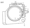
- in schematischer Darstellung das Batteriefach mit dem Betätigungselement in der zweiten Stellung;
- FIG 7
- das Betätigungselement mit einer Rastnase.
- Bei einem in
FIG 2 dargestellten Hinter-dem-Ohr-Hörgerät ist ein aus einem Gehäuse 1 herausragendes Betätigungselement 10 zum Ein- bzw. Ausschalten des Hörgeräts vorgesehen. - Wie in
FIG 3 wiedergegeben, ist das Betätigungselement 10 an einem Batteriefach 19 des Hörgeräts angeordnet. Das Betätigungselement 10 weist eine Schiebeplatte 11 auf, die in einen Ausschnitt 18 eines Rahmens 17 aufgenommen ist. Somit kann das Betätigungselement 10 entlang des Ausschnitts 18 verschoben werden. Darüber hinaus umfasst das Betätigungselement 10 ein quaderförmiges Abhebeelement 12, das an der Schiebeplatte 11 an einer gegenüber dem Betätigungselement 10 liegenden Seite der Schiebeplatte 11 angeordnet ist. Das Wesentliche hierbei ist, dass das Betätigungselement 10 aus dem Rahmen 17 und somit aus dem Gehäuse 1 des Hörgeräts hinausragt, und dass das lineare Verschieben des Betätigungselements 10 entlang des Ausschnitts 18 keinen Einfluss auf die greifbare Fläche des Betätigungselements 10 hat. - Wie ebenfalls in
FIG 3 dargestellt, befindet sich in dem Batteriefach 19 eine Batterie 5. In einer ersten inFIG 3 gezeigten Stellung des Betätigungselements 10 liegt an einer Abgreiffläche 13 der Batterie 5 ein Kontaktelement 14 an, das dort ein elektrisches Potential abgreift. Somit ist ein Stromkreis geschlossen und das Hörgerät eingeschaltet. Dabei berührt das Kontaktelement 14 die Batterie 5 lediglich über eine Kontaktstelle 20, die an einem Ende des Kontaktelements 14 angeordnet ist. Darüber hinaus weist das Kontaktelement 14 eine Anlaufschräge 15 auf, an der das Kontaktelement 14 abgehoben und von der Batterie entfernt werden kann. Die Kontaktstelle 20 ist von der Anlaufschräge 15 deutlich beabstandet. - In einer in
FIG 4 gezeigten zweiten Stellung des Betätigungselements 10, die durch ein lineares Verschieben des Betätigungselements 10 erreicht wird, hebt das Abhebeelement 12 das Kontaktelement 14 an dem Abhebeabschnitt 15 ab. Zu erkennen ist, dass das lineare Verschieben des Betätigungselements 10 entlang des Ausschnitts 18 eine Bewegung des Kontaktelements 14 im Wesentlichen senkrecht zu dem Ausschnitt 18 bewirkt, was auf die Anlaufschräge 15 des Kontaktelements 14 zurückzuführen ist. Gegebenenfalls, wenn das Kontaktelement 14 nicht unmittelbar durch das Abhebeelement 12, sondern mittels eines Hebelarms abgehoben wird, der im Wesentlichen parallel zu der Schiebeplatte 11 angeordnet werden kann, und wenn das Kontaktelement beispielsweise senkrecht zu dem Ausschnitt 18 angeordnet ist, kann die lineare Verschiebung des Betätigungselements 10 entlang des Ausschnitts 18 eine zu dem Ausschnitt 18 ebenfalls parallele Bewegung des Kontaktelements zur Folge haben. - Anhand eines in
FIG 5 gezeigten schematischen Aufbaus des Batteriefachs 19 ist die erste Stellung des Betätigungselements 10 wiedergegeben. Hierbei ist noch deutlicher zu erkennen, dass das elektrische Potential an der Abgreiffläche 13 der Batterie 5 von dem Kontaktelement 14 lediglich über die Kontaktstelle 20 abgegriffen wird. Durch eine Verschiebung des Betätigungselements 10, wie inFIG 6 , wird das Kontaktelement 14 durch das Abhebelelement 12 an der Anlaufschräge 15 abgehoben und somit die Kontaktstelle 20 des Kontaktelements 14 von der Batterie entfernt. Weil die Kontaktstelle 20 des Kontaktelements 14 nur die Abgreiffläche 13 der Batterie 5 und keine weiteren Stoffe berühren kann, wird dadurch ein Abkratzen von Material vermieden und die Kontaktstelle 20 bleibt immer kontaktfähig. - Die Schiebeplatte 11 des in
FIG 7 wiedergegebenen Betätigungselements 10 weist eine Rastnase 16 auf, die in der ersten und zweiten Stellung des Betätigungselements 10 in jeweils eine Aussparung im Rahmen oder Gehäuse des Hörgeräts hineinragt. Somit wird eine Stabilität des Betätigungselements 10 erreicht und einem Hörgeräteträger haptisch darauf hingedeutet, dass sich das Betätigungselement 10 in der ersten bzw. zweiten Stellung befindet und das Hörgerät ein- bzw. ausgeschaltet ist.
Claims (4)
- Hörvorrichtung mit- einem Batteriefach (19) zur Aufnahme einer Batterie (5),- einem Betätigungselement (10) zum Einschalten und/oder Ausschalten der Hörvorrichtung, das an dem Batteriefach (19) angeordnet ist und- einem Kontaktelement (14), das eine Kontaktstelle (20) aufweist, und das in einer ersten Stellung des Betätigungselements (10) über die Kontaktstelle (20) ein elektrisches Potential an der Batterie (5) abgreift,
dadurch gekennzeichnet, dass- das Betätigungselement (10) in einer gegenüber der ersten Stellung linear verschobenen zweiten Stellung das Kontaktelement (14) an einem von der Kontaktstelle (20) verschiedenen Abhebeabschnitt (15) des Kontaktelements (14) abhebt, um die Kontaktstelle (20) des Kontaktelements (14) von der Batterie (5) abzuheben. - Hörvorrichtung nach Anspruch 1, wobei der Abhebeabschnitt (15) des Kontaktelements (14) eine Anlaufschräge (15) aufweist, an welcher das Betätigungselement (10) das Kontaktelement (14) abhebt, und wobei die Anlaufschräge (15) derart ausgebildet ist, dass eine Bewegung des Betätigungselements (10) von der ersten zu der zweiten Stellung eine im Wesentlichen dazu senkrechte Bewegung des Kontaktelements (14) bewirkt.
- Hörvorrichtung nach Anspruch 1, wobei das Betätigungselement (10) in der zweiten Stellung das Kontaktelement (14) von der Batterie (5) mittels eines Hebelarms abhebt, der derart ausgebildet ist, dass eine Bewegung des Betätigungselements (10) von der ersten zu der zweiten Stellung eine im Wesentlichen dazu parallele Bewegung des Kontaktelements (14) bewirkt.
- Hörvorrichtung nach einem der vorhergehenden Ansprüche, wobei das Betätigungselement (10) eine Rastnase (16) aufweist, die in mindestens einer Stellung des Betätigungselements (10) in eine Öffnung eines Gehäuses (1) oder eines Rahmens (17) der Hörvorrichtung hineinragt, um das Betätigungselement (10) stabil zu halten.
Applications Claiming Priority (1)
| Application Number | Priority Date | Filing Date | Title |
|---|---|---|---|
| DE102007033876A DE102007033876B4 (de) | 2007-07-20 | 2007-07-20 | Hörvorrichtung mit linearem Schalter |
Publications (2)
| Publication Number | Publication Date |
|---|---|
| EP2026603A2 true EP2026603A2 (de) | 2009-02-18 |
| EP2026603A3 EP2026603A3 (de) | 2010-12-29 |
Family
ID=40157062
Family Applications (1)
| Application Number | Title | Priority Date | Filing Date |
|---|---|---|---|
| EP08104474A Withdrawn EP2026603A3 (de) | 2007-07-20 | 2008-06-19 | Hörvorrichtung mit linearem Schalter |
Country Status (3)
| Country | Link |
|---|---|
| US (1) | US8155360B2 (de) |
| EP (1) | EP2026603A3 (de) |
| DE (1) | DE102007033876B4 (de) |
Citations (2)
| Publication number | Priority date | Publication date | Assignee | Title |
|---|---|---|---|---|
| US3475566A (en) | 1966-01-04 | 1969-10-28 | Sonotone Corp | Battery holder and switch for hearing aid unit |
| US4230777A (en) | 1979-04-02 | 1980-10-28 | Motorola, Inc. | Battery holder with integral access door and power switch |
Family Cites Families (9)
| Publication number | Priority date | Publication date | Assignee | Title |
|---|---|---|---|---|
| US3138491A (en) * | 1962-04-09 | 1964-06-23 | Beltone Electronics Corp | Combination switch and battery holder |
| DE1242736B (de) * | 1965-09-09 | 1967-06-22 | Eisemann G M B H | Elektrischer Schiebeschalter |
| US3701862A (en) * | 1971-04-16 | 1972-10-31 | Gould Inc | Battery holder and three-position switch for hearing aid unit |
| EP0035979B1 (de) * | 1980-03-11 | 1984-07-11 | Soc. F.A.M.A. di Sandra Borgato & CO.S.n.c. | Von Hand und elektrisch betriebener selbsttätiger Hakenverschluss |
| EP0254925A1 (de) * | 1986-07-21 | 1988-02-03 | Siemens Aktiengesellschaft | Hörgerät mit einer Kontaktfederanordnung |
| US5251105A (en) | 1990-06-25 | 1993-10-05 | Kabushiki Kaisha Toshiba | Portable electronic apparatus having a battery pack with a mechanism for latching and an independent mechanism for temporarily preventing detachment |
| JPH0462896A (ja) * | 1990-06-25 | 1992-02-27 | Toshiba Corp | 小型電子機器 |
| DE4331382C1 (de) * | 1993-09-15 | 1994-11-10 | Siemens Audiologische Technik | Betätigungsvorrichtung für Hörgeräte |
| US5687242A (en) * | 1995-08-11 | 1997-11-11 | Resistance Technology, Inc. | Hearing aid controls operable with battery door |
-
2007
- 2007-07-20 DE DE102007033876A patent/DE102007033876B4/de not_active Expired - Fee Related
-
2008
- 2008-06-19 EP EP08104474A patent/EP2026603A3/de not_active Withdrawn
- 2008-07-21 US US12/176,754 patent/US8155360B2/en not_active Expired - Fee Related
Patent Citations (2)
| Publication number | Priority date | Publication date | Assignee | Title |
|---|---|---|---|---|
| US3475566A (en) | 1966-01-04 | 1969-10-28 | Sonotone Corp | Battery holder and switch for hearing aid unit |
| US4230777A (en) | 1979-04-02 | 1980-10-28 | Motorola, Inc. | Battery holder with integral access door and power switch |
Also Published As
| Publication number | Publication date |
|---|---|
| US20090022347A1 (en) | 2009-01-22 |
| DE102007033876A1 (de) | 2009-01-29 |
| EP2026603A3 (de) | 2010-12-29 |
| DE102007033876B4 (de) | 2012-04-19 |
| US8155360B2 (en) | 2012-04-10 |
Similar Documents
| Publication | Publication Date | Title |
|---|---|---|
| EP2053876B1 (de) | Hörvorrichtung mit gemeinsamem Anschluss für Schirmung und Identifikation eines Hörers | |
| EP3094111B1 (de) | Hörgerät | |
| DE102009056916B4 (de) | Hörgerät mit einer platzsparenden Anordnung von Mikrofonen und Schallöffnungen | |
| EP2285136A1 (de) | Hörhilfe mit wechselbarem Hörer | |
| DE102008008668A1 (de) | Hörvorrichtung mit Batteriefachrastung | |
| DE102008054087A1 (de) | Hörhilfegerät mit mindestens einem kapazitiven Näherungssensor | |
| DE102007008551A1 (de) | Hörvorrichtung mit magnetisch befestigtem Batteriefach | |
| WO2019105949A1 (de) | Modulares hörgerät | |
| EP1959712A2 (de) | Hörvorrichtung mit Hörerkompensationsspule | |
| EP2574083A2 (de) | IDO-Hörinstrument mit Programmierbuchse | |
| DE102008020926A1 (de) | Drucktaster für ein Hörgerät | |
| EP2091124A2 (de) | Ladegerät für eine Hörvorrichtung mit einem bewegbaren Ladekontakt und zugehöriges Hörgerätesystem | |
| DE102010009702A1 (de) | Hörvorrichtung mit einem Leitelement, insbesondere einem Schallschlauch | |
| DE102007033876B4 (de) | Hörvorrichtung mit linearem Schalter | |
| EP2592849B1 (de) | Hörvorrichtung mit einem Batteriefach | |
| EP3197180B1 (de) | Hörgerät | |
| DE102007054603B4 (de) | Hörvorrichtung mit gesteuerter Programmierbuchse | |
| EP2222094B1 (de) | Gehäuse für eine Hörvorrichtung mit Sicherungselement | |
| EP3192277A1 (de) | Hörinstrument und verfahren zum betrieb eines hörinstruments | |
| EP1909535B1 (de) | Hörvorrichtung mit gesteuerten Eingangskanälen und entsprechendes Verfahren | |
| DE102011004966A1 (de) | Hörvorrichtung mit Sensoreinheit | |
| DE102010014315A1 (de) | Hörinstrument mit Bedienvorrichtung | |
| EP2040489B1 (de) | Hörvorrichtung mit unterschiedlich gelagertem Bedienelement | |
| DE102020201480A1 (de) | Hörgerät | |
| EP1973376A1 (de) | Hörvorrichtung mit entnehmbarem Lautstärkestellermodul |
Legal Events
| Date | Code | Title | Description |
|---|---|---|---|
| PUAI | Public reference made under article 153(3) epc to a published international application that has entered the european phase |
Free format text: ORIGINAL CODE: 0009012 |
|
| AK | Designated contracting states |
Kind code of ref document: A2 Designated state(s): AT BE BG CH CY CZ DE DK EE ES FI FR GB GR HR HU IE IS IT LI LT LU LV MC MT NL NO PL PT RO SE SI SK TR |
|
| AX | Request for extension of the european patent |
Extension state: AL BA MK RS |
|
| PUAL | Search report despatched |
Free format text: ORIGINAL CODE: 0009013 |
|
| AK | Designated contracting states |
Kind code of ref document: A3 Designated state(s): AT BE BG CH CY CZ DE DK EE ES FI FR GB GR HR HU IE IS IT LI LT LU LV MC MT NL NO PL PT RO SE SI SK TR |
|
| AX | Request for extension of the european patent |
Extension state: AL BA MK RS |
|
| RIC1 | Information provided on ipc code assigned before grant |
Ipc: H01M 2/10 20060101ALI20101124BHEP Ipc: H04R 25/00 20060101AFI20090115BHEP |
|
| 17P | Request for examination filed |
Effective date: 20110404 |
|
| AKX | Designation fees paid |
Designated state(s): AT BE BG CH CY CZ DE DK EE ES FI FR GB GR HR HU IE IS IT LI LT LU LV MC MT NL NO PL PT RO SE SI SK TR |
|
| 17Q | First examination report despatched |
Effective date: 20111108 |
|
| GRAP | Despatch of communication of intention to grant a patent |
Free format text: ORIGINAL CODE: EPIDOSNIGR1 |
|
| STAA | Information on the status of an ep patent application or granted ep patent |
Free format text: STATUS: THE APPLICATION IS DEEMED TO BE WITHDRAWN |
|
| 18D | Application deemed to be withdrawn |
Effective date: 20121023 |