EP2026028A2 - Heat exchanger, more particularly for automotive vehicle - Google Patents
Heat exchanger, more particularly for automotive vehicle Download PDFInfo
- Publication number
- EP2026028A2 EP2026028A2 EP08018381A EP08018381A EP2026028A2 EP 2026028 A2 EP2026028 A2 EP 2026028A2 EP 08018381 A EP08018381 A EP 08018381A EP 08018381 A EP08018381 A EP 08018381A EP 2026028 A2 EP2026028 A2 EP 2026028A2
- Authority
- EP
- European Patent Office
- Prior art keywords
- heat exchanger
- plate
- tube
- tubes
- refrigerant
- Prior art date
- Legal status (The legal status is an assumption and is not a legal conclusion. Google has not performed a legal analysis and makes no representation as to the accuracy of the status listed.)
- Granted
Links
Images


Classifications
-
- F—MECHANICAL ENGINEERING; LIGHTING; HEATING; WEAPONS; BLASTING
- F28—HEAT EXCHANGE IN GENERAL
- F28F—DETAILS OF HEAT-EXCHANGE AND HEAT-TRANSFER APPARATUS, OF GENERAL APPLICATION
- F28F9/00—Casings; Header boxes; Auxiliary supports for elements; Auxiliary members within casings
- F28F9/02—Header boxes; End plates
- F28F9/026—Header boxes; End plates with static flow control means, e.g. with means for uniformly distributing heat exchange media into conduits
- F28F9/0278—Header boxes; End plates with static flow control means, e.g. with means for uniformly distributing heat exchange media into conduits in the form of stacked distribution plates or perforated plates arranged over end plates
-
- F—MECHANICAL ENGINEERING; LIGHTING; HEATING; WEAPONS; BLASTING
- F28—HEAT EXCHANGE IN GENERAL
- F28D—HEAT-EXCHANGE APPARATUS, NOT PROVIDED FOR IN ANOTHER SUBCLASS, IN WHICH THE HEAT-EXCHANGE MEDIA DO NOT COME INTO DIRECT CONTACT
- F28D1/00—Heat-exchange apparatus having stationary conduit assemblies for one heat-exchange medium only, the media being in contact with different sides of the conduit wall, in which the other heat-exchange medium is a large body of fluid, e.g. domestic or motor car radiators
- F28D1/02—Heat-exchange apparatus having stationary conduit assemblies for one heat-exchange medium only, the media being in contact with different sides of the conduit wall, in which the other heat-exchange medium is a large body of fluid, e.g. domestic or motor car radiators with heat-exchange conduits immersed in the body of fluid
- F28D1/04—Heat-exchange apparatus having stationary conduit assemblies for one heat-exchange medium only, the media being in contact with different sides of the conduit wall, in which the other heat-exchange medium is a large body of fluid, e.g. domestic or motor car radiators with heat-exchange conduits immersed in the body of fluid with tubular conduits
- F28D1/047—Heat-exchange apparatus having stationary conduit assemblies for one heat-exchange medium only, the media being in contact with different sides of the conduit wall, in which the other heat-exchange medium is a large body of fluid, e.g. domestic or motor car radiators with heat-exchange conduits immersed in the body of fluid with tubular conduits the conduits being bent, e.g. in a serpentine or zig-zag
- F28D1/0477—Heat-exchange apparatus having stationary conduit assemblies for one heat-exchange medium only, the media being in contact with different sides of the conduit wall, in which the other heat-exchange medium is a large body of fluid, e.g. domestic or motor car radiators with heat-exchange conduits immersed in the body of fluid with tubular conduits the conduits being bent, e.g. in a serpentine or zig-zag the conduits being bent in a serpentine or zig-zag
- F28D1/0478—Heat-exchange apparatus having stationary conduit assemblies for one heat-exchange medium only, the media being in contact with different sides of the conduit wall, in which the other heat-exchange medium is a large body of fluid, e.g. domestic or motor car radiators with heat-exchange conduits immersed in the body of fluid with tubular conduits the conduits being bent, e.g. in a serpentine or zig-zag the conduits being bent in a serpentine or zig-zag the conduits having a non-circular cross-section
-
- F—MECHANICAL ENGINEERING; LIGHTING; HEATING; WEAPONS; BLASTING
- F28—HEAT EXCHANGE IN GENERAL
- F28D—HEAT-EXCHANGE APPARATUS, NOT PROVIDED FOR IN ANOTHER SUBCLASS, IN WHICH THE HEAT-EXCHANGE MEDIA DO NOT COME INTO DIRECT CONTACT
- F28D1/00—Heat-exchange apparatus having stationary conduit assemblies for one heat-exchange medium only, the media being in contact with different sides of the conduit wall, in which the other heat-exchange medium is a large body of fluid, e.g. domestic or motor car radiators
- F28D1/02—Heat-exchange apparatus having stationary conduit assemblies for one heat-exchange medium only, the media being in contact with different sides of the conduit wall, in which the other heat-exchange medium is a large body of fluid, e.g. domestic or motor car radiators with heat-exchange conduits immersed in the body of fluid
- F28D1/04—Heat-exchange apparatus having stationary conduit assemblies for one heat-exchange medium only, the media being in contact with different sides of the conduit wall, in which the other heat-exchange medium is a large body of fluid, e.g. domestic or motor car radiators with heat-exchange conduits immersed in the body of fluid with tubular conduits
- F28D1/053—Heat-exchange apparatus having stationary conduit assemblies for one heat-exchange medium only, the media being in contact with different sides of the conduit wall, in which the other heat-exchange medium is a large body of fluid, e.g. domestic or motor car radiators with heat-exchange conduits immersed in the body of fluid with tubular conduits the conduits being straight
- F28D1/0535—Heat-exchange apparatus having stationary conduit assemblies for one heat-exchange medium only, the media being in contact with different sides of the conduit wall, in which the other heat-exchange medium is a large body of fluid, e.g. domestic or motor car radiators with heat-exchange conduits immersed in the body of fluid with tubular conduits the conduits being straight the conduits having a non-circular cross-section
- F28D1/05366—Assemblies of conduits connected to common headers, e.g. core type radiators
- F28D1/05391—Assemblies of conduits connected to common headers, e.g. core type radiators with multiple rows of conduits or with multi-channel conduits combined with a particular flow pattern, e.g. multi-row multi-stage radiators
-
- F—MECHANICAL ENGINEERING; LIGHTING; HEATING; WEAPONS; BLASTING
- F28—HEAT EXCHANGE IN GENERAL
- F28F—DETAILS OF HEAT-EXCHANGE AND HEAT-TRANSFER APPARATUS, OF GENERAL APPLICATION
- F28F1/00—Tubular elements; Assemblies of tubular elements
- F28F1/02—Tubular elements of cross-section which is non-circular
-
- F—MECHANICAL ENGINEERING; LIGHTING; HEATING; WEAPONS; BLASTING
- F28—HEAT EXCHANGE IN GENERAL
- F28F—DETAILS OF HEAT-EXCHANGE AND HEAT-TRANSFER APPARATUS, OF GENERAL APPLICATION
- F28F9/00—Casings; Header boxes; Auxiliary supports for elements; Auxiliary members within casings
- F28F9/02—Header boxes; End plates
- F28F9/0219—Arrangements for sealing end plates into casing or header box; Header box sub-elements
- F28F9/0221—Header boxes or end plates formed by stacked elements
-
- F—MECHANICAL ENGINEERING; LIGHTING; HEATING; WEAPONS; BLASTING
- F28—HEAT EXCHANGE IN GENERAL
- F28D—HEAT-EXCHANGE APPARATUS, NOT PROVIDED FOR IN ANOTHER SUBCLASS, IN WHICH THE HEAT-EXCHANGE MEDIA DO NOT COME INTO DIRECT CONTACT
- F28D21/00—Heat-exchange apparatus not covered by any of the groups F28D1/00 - F28D20/00
- F28D2021/0019—Other heat exchangers for particular applications; Heat exchange systems not otherwise provided for
- F28D2021/0068—Other heat exchangers for particular applications; Heat exchange systems not otherwise provided for for refrigerant cycles
- F28D2021/0073—Gas coolers
-
- F—MECHANICAL ENGINEERING; LIGHTING; HEATING; WEAPONS; BLASTING
- F28—HEAT EXCHANGE IN GENERAL
- F28D—HEAT-EXCHANGE APPARATUS, NOT PROVIDED FOR IN ANOTHER SUBCLASS, IN WHICH THE HEAT-EXCHANGE MEDIA DO NOT COME INTO DIRECT CONTACT
- F28D21/00—Heat-exchange apparatus not covered by any of the groups F28D1/00 - F28D20/00
- F28D2021/0019—Other heat exchangers for particular applications; Heat exchange systems not otherwise provided for
- F28D2021/008—Other heat exchangers for particular applications; Heat exchange systems not otherwise provided for for vehicles
- F28D2021/0085—Evaporators
-
- F—MECHANICAL ENGINEERING; LIGHTING; HEATING; WEAPONS; BLASTING
- F28—HEAT EXCHANGE IN GENERAL
- F28F—DETAILS OF HEAT-EXCHANGE AND HEAT-TRANSFER APPARATUS, OF GENERAL APPLICATION
- F28F2280/00—Mounting arrangements; Arrangements for facilitating assembling or disassembling of heat exchanger parts
Definitions
- the invention relates to a heat exchanger with pipes and with an end piece, which has a tube plate consisting of plates.
- Such a heat exchanger is for example in the EP 0 563 471 A1 described.
- the local heat exchanger is designed as a double-row flat tube evaporator, which is flowed through in two bends. Between the flat tubes are corrugated fins, which are covered by ambient air.
- the refrigerant flows through the seen in the main flow direction of the air rear row of flat tubes first from top to bottom and is then collected and deflected by a deflector against the flow direction of the air, enters the first, ie front row of flat tubes and flows through them from bottom to top. In this design, the refrigerant is thus deflected "in the depth", ie counter to the flow direction of the air.
- the flow paths for the refrigerant each comprise two sections, each section corresponding to a tube length.
- the distribution and collection of the refrigerant is carried out by a collecting and distributing device, which is formed by a plurality of stacked, soldered together plates. It is in the essentially around a bottom plate, an overlying distributor plate with a longitudinally extending partition and a cover plate with inlet and outlet opening for the refrigerant.
- the deflector arranged on the opposite side is composed of individual plates. This results in a low overall height for this evaporator.
- a so-called stop plate is provided, which is placed in each case on the bottom plate and forms a stop for the pipe ends.
- a disadvantage of this evaporator design is that the refrigerant is distributed unevenly on the individual tubes due to the over the entire width of the evaporator extending distribution or collection chamber.
- the double-row design requires increased installation costs.
- An evaporator for a fuel cell system which includes a header having a bottom plate and a cover plate attached thereto. Fuel passes through a connecting part in a fuel distribution chamber, from there into guide channels and through openings in the bottom plate in heat receiving ducts of the evaporator.
- the plates of the head are small in number, but very expensive in their production.
- the heat receiving channels are acted upon very unevenly depending on the pressure distribution in the fuel distributor chamber and in the guide channels with fuel.
- the object of the invention is to provide a heat exchanger in which a simple and / or lightweight construction and optionally at the same time a uniform distribution of a medium to a plurality of flow paths and / or a pressure-stable construction of the heat exchanger can be realized.
- a heat exchanger according to the invention on tubes which can be flowed through by a first medium and a second medium flow around, so that through walls of the tubes Heat from the first to the second medium or vice versa transferable.
- there are heat transfer channels in the tubes, through which the first medium can be conducted wherein a single tube has either a heat transfer channel or as a so-called multi-chamber tube a plurality of adjacent heat transfer channels.
- the tubes may have a circular, an oval, a substantially rectangular or any other cross section.
- the tubes are designed as flat tubes.
- optionally ribs, in particular corrugated fins are arranged between the tubes, wherein the tubes and the ribs are in particular solderable to one another.
- the heat exchanger various uses are conceivable, for example as an evaporator of a refrigerant circuit, in particular an automotive air conditioning system.
- the first medium is a refrigerant, for example, R134a or R744
- the second medium is air, whereby heat is transferred from the air to the refrigerant.
- the heat exchanger is also suitable for other media, where appropriate, the heat is also transferable from the first to the second medium.
- At least two collection chambers are present, wherein the first medium can be conducted from a first to a second collection chamber.
- the first medium can be conducted along one or more flow paths, which optionally consist of several sections.
- a flow path section in the sense of the invention is to be understood as meaning one or more heat transfer channels which run from one side of the heat exchanger to an opposite side and are connected hydraulically in parallel to one another.
- the heat transfer channels of a flow path section are arranged, for example, in a single tube, one on several tubes However, distributed arrangement of the heat transfer channels of a flow path section is also conceivable.
- the heat exchanger has an end piece with a tube plate, which consists of adjacent plates, namely a bottom plate, a baffle plate and a cover plate.
- the bottom plate is connectable to ends of the tubes by the bottom plate, for example, has recesses into which the pipe ends are receivable.
- other types of connection between pipes and the bottom plate are conceivable, for example, by extensions at the edges of recesses in the bottom plate, so that the tubes are attachable to the extensions.
- Recesses in the deflection plate serve for the formation of passage channels and / or deflection channels, which can be closed fluid-tight with respect to an environment of the heat exchanger with a cover plate. Due to the plate structure of the tube plate a very pressure-stable construction of the tail and the entire heat exchanger is possible.
- a first basic idea of the invention is to provide the end piece comprising the tubesheet with a collection box which has at least one collection chamber for the first medium in a housing.
- flow path sections are connected to one another by means of deflection channels in the deflection plate.
- the interconnection of the flow path sections to one or more hydraulically parallel flow paths can then be interpreted according to any requirements by a single plate, namely the baffle plate, corresponding to the required flow path connection is configured.
- the heat exchanger can be built flexibly for various applications due to its modular design.
- a tube is introduced into the tubesheet up to a predetermined stop in order to achieve increased manufacturing reliability and thus simplified production.
- the stop is realized by a web between two recesses in the bottom plate, which is receivable in a recess in a pipe end, wherein the web is substantially as wide as the recess in the pipe end.
- the recess is slightly wider than the web to facilitate insertion of the tube into the bottom plate.
- the insertion depth of the tube is given by the height of the recess in the pipe end.
- the recess is higher than the web, whereby the risk of unwanted clogging of one or more heat transfer channels by solder located on the bottom plate during a. Soldering process is reduced.
- the height difference is, for example, 1 mm or more, on the other hand, should be less than the thickness of the baffle, since the pipe otherwise abuts the cover plate.
- a height difference that is about half as large as the thickness of the baffle plate.
- Another basic idea of the invention is to design a plurality of plates of the tubesheet in one piece in order to reduce the number of production and, if necessary, the cost of materials.
- the tube plate then only consists of a plate in which the bottom plate, the baffle plate and the cover plate are integrated.
- the cost of materials for the tube plate and thus also for the heat exchanger is reduced by one or more, preferably all plates of the tubesheet have additional recesses between passage and / or deflection channels, the For example, as breakthroughs or lateral indentations are formed.
- the plates are severed between passage and / or deflection channels, whereby the plates may disintegrate into many small sub-plates. This allows a particularly lightweight construction, which has a positive effect on material costs and weight of the heat exchanger alike.
- a simplified construction is made possible according to a further basic idea of the invention by U-shaped tubes, wherein the tubes are simply or repeatedly formed into an even simpler construction.
- two pipe-floor connections and optionally a deflection channel are saved.
- Another idea of the invention is to provide the heat exchanger with exactly one end piece, in which in particular a collecting box is integrated with two collecting chambers. This is possible except through the use of U-tubes through any conceivable hydraulic connection of pipes on a side opposite exactly one end of the heat exchanger, for example by placing suitably constructed caps on a plurality of, in particular two tubes.
- an optionally integrated into the tail collecting tank with the cover plate is soldered fluid-tight or welded.
- the collecting box is integrally formed with the cover plate, whereby the production is simplified.
- a particularly lightweight design is achieved by a tubular design of the collecting tank according to a further embodiment of the invention.
- the cover plate on edges of openings on extensions which engage in openings of a housing of the collecting tank.
- it is possible according to a further embodiment to provide apertures of the Samrnelkastengephases with extensions which engage in openings of the cover plate. In both cases, the manufacturing safety is increased by an alignment of the mutually aligned openings in the cover plate and in the collection box housing.
- the passage openings which are formed by the mutually aligned openings in the cover plate and in the collection box housing, have different flow cross-sections.
- an adaptation of the distribution of the first medium to the flow conditions in the associated collection chamber is made possible in a simple manner.
- a uniform distribution over a plurality of flow paths is desirable, but also a deliberately uneven distribution is conceivable, for example, at uneven mass flow of the second medium over an end face of the heat exchanger.
- the passage openings are arranged with different flow cross-sections upstream of the heat transfer channels, whereby the flow in the flow paths is particularly easily compensated.
- the passage openings on the outlet side can be made larger, for example with a flow cross section which corresponds to the flow cross section of the respective flow path.
- the Heat exchangers for example, used as an evaporator in a refrigerant circuit, the pressure conditions along the circuit are more advantageous for the performance of the heat exchanger when flow cross sections are narrowed before heating the refrigerant, as in a narrowing of the flow cross sections after heating.
- the flow cross-sections of the passage openings are adaptable according to an embodiment of a pressure distribution of the first medium within the respective collection chamber.
- the flow cross sections can be adapted to a density distribution of the first medium within the respective collection chamber.
- the density of a medium is to be understood as the physical density in single-phase media, while in the case of multiphase media, for example in media which are partly liquid and partly gaseous, a density averaged over the volume in question is to be understood.
- the cross sectional areas of the first and second plenums are different from one another in a preferred embodiment.
- the cross-sectional areas of the collecting chambers can be adapted to the density ratios of the first medium in the chambers.
- heat exchanger according to the invention relate to the interconnection of the flow path sections by means of deflection channels in the deflection plate.
- flow path sections which are arranged side by side in the main flow direction of the second medium are connected to one another by a deflection channel are.
- One speaks then of a deflection in the width This makes it possible to connect several or possibly all flow path sections within a row or within a row of pipes together to form a flow path.
- the interconnected flow path sections are aligned in the main flow direction of the second medium.
- One speaks then of a deflection in the depth This makes it possible to connect flow paths for the first medium parallel or antiparallel to the main flow direction of the second medium. This leads to an at least partial countercurrent construction of the heat exchanger.
- two flow path sections are interconnected within a tube by a deflection channel. This means that the first medium flows in one direction through the tube and flows back in the opposite direction through the same tube.
- the number of sections of at least one flow path is divisible by two.
- a two-row arrangement of the flow path sections is easily interconnected by the first half of the sections of a flow path arranged in a first row and connected by deflections in the width, whereas the second half of the sections arranged in a second row and also through Deflections in the width is connected to each other, wherein the two halves of the flow path are connected by a deflection in the depth.
- This deflection in depth is done for example in a deflection of a baffle plate of a tube plate or the Collection chambers opposite side of the heat exchanger.
- the number of sections of the flow path is divisible by four.
- the first and last flow path sections within one or more rows of tubes are not acted upon as hydraulically first sections of flow paths, since the flow and / or pressure conditions of the first medium are unfavorable for application in the edge region of collection chambers, which are usually arranged along rows of tubes of flow paths are.
- two adjacent flow paths are mirror-symmetrical to each other.
- deflection channels communicate at least two flow paths.
- an additional compensation of the flow is effected within the flow paths.
- it is particularly easy to communicate the optionally adjacent deflection channels for example by omitting a web which may otherwise be present between two deflection channels.
- a flow cross section of a flow path changes during its course. This is very easy to realize, for example, by flow path sections with few heat transfer channels over correspondingly configured deflection channels with flow path sections are connected to many heat transfer channels. An adaptation of the flow cross section of a flow path to a density of the first medium changing along the flow path is particularly preferred.
- An embodiment is advantageous in which all sections of at least one flow path in the main flow direction of the second medium are aligned with one another. Particularly advantageously, all flow paths of the heat exchanger are formed in this manner, whereby a pure countercurrent construction of the heat exchanger in a simple manner, namely by appropriately configured deflection channels in a baffle is possible.
- the heat exchanger consists of flat tubes through which a liquid and / or vapor refrigerant flows, corrugated fins exposed to ambient air, a collection and distribution device for the supply and removal of the refrigerant, arranged between the flat tubes.
- each one flat tube has two parallel flow sections, which flows through one after the other and are connected via the deflection, wherein each flat tube end a groove between the two flow Sections in the middle of the flat tube end and that the bottom plate between the receiving openings webs, which in terms of their dimensions Height and width correspond to the grooves and each form a joint connection with the grooves.
- the deflection device is formed by a further base plate with receiving openings and webs, which form a joint connection with the end-side groove of the flat tubes.
- the deflection device additionally has a channel plate with through slots and a closed cover plate.
- the collecting and distributing device has a channel plate with channel openings and webs between the channel openings, a cover plate with refrigerant inlet and -austrittsö réelleen and a refrigerant supply and a refrigerant discharge channel, which are arranged parallel to each other and in the longitudinal direction of the heat exchanger on wherein the bottom plate, the channel plate and the cover plate are arranged one above the other in such a way that the openings in the plates are aligned with the flat tube ends.
- the refrigerant inlet openings are formed as calibrated bores, wherein the diameter of the bores is in particular variable.
- the cover plate and the refrigerant supply and -abbowkanäle are integrally formed.
- the heat exchanger which is particularly useful as an evaporator for motor vehicle air conditioners, consisting of flat tubes, which are flowed through by a liquid and / or vapor refrigerant, arranged between the flat tubes, acted upon by ambient air corrugated fins, a collecting and distributing device for the supply and the removal of the refrigerant, wherein the Collection and distribution device consists of a plurality of stacked, perforated plates, whereby refrigerant channels are formed, wherein the ends of the flat tubes are held in receiving openings of a bottom plate, and a deflection device for deflecting the refrigerant in the flow direction of the ambient air.
- the heat exchanger consists of a series of flat tubes, wherein in each case a flat tube two parallel flow sections, which are successively flowed through and connected via the deflection, and wherein the collecting and distributing device has a between refrigerant inlet and outlet arranged calibration device, which serves as a cover plate is formed with calibration openings for the refrigerant distribution.
- the calibration openings are arranged on the refrigerant inlet side.
- the calibration openings have different flow cross sections.
- the flow cross sections of the calibration openings are preferably larger in the direction of the pressure drop of the refrigerant in the feed channel.
- the flow cross sections of the calibration openings are variable depending on the specific volume of the refrigerant or its vapor content.
- the flat tubes are designed as serpentine segments and the deflection device is arranged in the collecting and distributing device.
- the collecting and distributing device has a channel plate with through-channel openings for deflecting the refrigerant and channel openings with webs, a cover plate with refrigerant inlet and outlet openings and a refrigerant supply and a refrigerant discharge channel.
- the channel openings with webs are in each case with the first flat tube end of the Serpentine segment arranged in alignment, whereas the through-channel openings are arranged in alignment with the second flat tube end of the serpentine segment, wherein the refrigerant inlet and -austrittsö réelleen are aligned with the channel openings and the through-channel openings are covered by the cover plate.
- the serpentine segments have two or three deflections in width.
- the flat tubes are designed as U-tubes, that is, each with a deflection (in width).
- Two U-tubes are particularly preferably connected in series on the refrigerant side, and two adjacent channel openings, which are assigned to a U-tube outlet and a U-tube inlet, are in refrigerant communication with each other through a transverse channel in the channel plate.
- the width b of the channel openings in the channel plate is greater than the width a of the receiving openings in the bottom plate.
- the depth of the groove in the flat tube ends is greater than the thickness of the bottom plate.
- one or more of the following dimensions apply to the heat exchanger: Width: 200 to 360 mm, in particular. 260 to 315 mm Height: 180 to 280 mm, in particular. 200 to 250 mm Depth: 30 to 80 mm, preferably 35 to 65 mm Volume: 0.003 to 0.006 m3, in particular.
- Fig. 1 shows as the first embodiment, an evaporator for an operated with CO 2 as a refrigerant automotive air conditioning system, in an exploded view.
- This evaporator 1 is designed as a single-row flat tube evaporator and has a plurality of flat tubes, of which only two flat tubes 2, 3 are shown.
- These flat tubes 2, 3 are formed as extruded multi-chamber flat tubes, which have a plurality of flow channels 4. All flat tubes 2, 3 have the same length I and the same depth t.
- a groove 5, 6 symmetrical to the central axis 2c in the flat tube 2 is incorporated.
- the corrugated fins 7 are continuous in the depth direction, but may also be interrupted, for example in the middle of the depth t, in order to ensure better condensate drainage and / or thermal separation.
- a bottom plate 8 is shown, in which a first row of slot-shaped openings 9a - 9f and a second series of such openings 10a - 10f are arranged.
- the openings 9a and 10a, 9b and 10b, etc. lie in the direction of the depth (air flow direction L) one behind the other and leave between each webs 11a, 11b - 11f. With regard to their width in the depth direction, these webs 11a-11f correspond to the width of the cutout 5 of the pipe ends 2a.
- the number of openings 9a-9f or 10a-10f corresponds to the number of flat tubes 2, 3.
- baffle 12 in which two rows of openings 13a - 13f and 14a - 14f (partially hidden) are arranged.
- the arrangement of the apertures 13a-f and 14a-f corresponds to the arrangement of the apertures 9a-9f or 10a-10f, however, the apertures 13a-f and 14a-f are larger in their width b and depth than the corresponding dimensions of the apertures 9a - 9f or 10a - 10f, each having only a width of a, which corresponds to the thickness of the flat tubes 2, 3.
- Between the openings 13a, 14a, 13b, 14b - 13f u. 14f are each webs 15a - 15f left. With regard to their dimensions in the depth direction, these webs 15a-15f are smaller than the corresponding dimensions of the webs 11a-11f of the bottom plate 8.
- a so-called cover plate 16 which has a first row of refrigerant inlet openings 17a-17f and a second row of refrigerant outlet openings 18a-18f.
- These openings 17a - 17f u. 18a-18f are preferably formed as circular bores and adapted in terms of their diameter to the desired refrigerant distribution or flow rate.
- a collecting box 19 with a housing and in each case a collecting chamber 20, 21 for the supply and the discharge of the refrigerant.
- the collection box has openings 22a-f and 23a-f for both collection chambers on its underside, shown in dashed lines, which correspond in terms of position and size to the openings 17a-f and 18a-f.
- a further bottom plate 24 which has two rows of slot-shaped openings 25a-f and 26a-f analogous to the first bottom plate 8. Also located between the openings 25a and 26a to 25f and 26f are webs 27a-f (partially concealed), these webs, with respect to their width in the depth direction, corresponding to the width of the recess 6 in the end of the flat tube 2.
- a further baffle plate 28 is shown, the continuous deflection channels 29a - 29f has. These deflection channels 29a-f extend over the entire depth t of the flat tubes 2, 3.
- a cover plate 30 which has no openings, but closes the deflection channels 29a-29f with respect to the surroundings of the heat exchanger.
- the above-described constituent parts of the evaporator 1 are mounted as follows: On the flat tube ends 2a, etc., the bottom plate 8 is placed, so that the webs 11a - 11f come to lie in the recesses 5 of the flat tube ends. About the bottom plate 8 then the baffle 12, the cover plate 16 and the collection box 19 with the collection chambers 20, 21 are stacked. In an analogous manner, the lower bottom plate 24 is pushed onto the flat tube ends 2b, so that the webs 27a - 27f come to lie in the recesses 6; Thereafter, the channel plate 28 and the cover plate 29 are added. After the evaporator 1 is thus joined together, it is soldered in a soldering furnace to form a solid block. During the soldering process, the plates by a form or non-positive tension held in position to each other. But it is also possible to first mount the tail of base plate, baffle and cover plate and then connect with flat tubes.
- the refrigerant in this case CO 2 , thus flows through the evaporator initially on the front side from top to bottom, specifically in the front section 2 d of the flat tube 2, in the lower, consisting of the plates 24, 28, 30 tube plate in depth deflected and flows on the back of the evaporator 1, ie in the rear flow section 2e of the flat tube 2 from bottom to top, corresponding to the arrows R1, R2 and R3 to the collection chamber 21st
- Fig. 2 shows a further embodiment of the invention, namely an evaporator 40, in which the aforementioned flat tubes are formed as serpentine segments 41.
- a serpentine segment 41 consists of four flat tube legs 42, 43, 44 u. 45, which are interconnected by three Umlenkbögen 46, 47, 48. Between the individual Flachrohrschenkeln 42 - 45 corrugated fins 49 are arranged.
- the other parts of the evaporator are also shown in an exploded view, ie a bottom plate 50, a baffle 51, a cover plate 52 and collecting chambers 53, 54 for a refrigerant supply or removal.
- the bottom plate 50 has a front row of slot-shaped openings 55 a, 55 b u.
- This web 60a is in turn smaller than the recess 58 of the flat tube leg 42.
- a deflection channel 61 Adjacent to the opening 59a and at a distance corresponding to that of the flat tube ends 42a-45a, a deflection channel 61 is arranged which extends over the entire depth of the flat tube leg 45. Adjacent to the deflection channel 61 then follows an opening 59b, which corresponds in size to the opening 59a. It corresponds to the next Flachrohrserpentinensegment, which is not shown here.
- Above the baffle 51 is the cover plate 52, in the front row two refrigerant supply openings 62, 63 and in the rear row two refrigerant outlets 64 u. 65 has. The latter correspond in terms of size and location with the dashed lines in the collection chambers 53, 54 openings (without reference number).
- the refrigerant flow path is illustrated by arrows: First, the refrigerant leaves the collection chamber 53 via the arrow E1, then follows the arrows E2, E3, E4 and enters the front flow section of the flat tube leg 42 and flows through the entire serpentine segment 41 on its front side and enters E6 from the last leg 45, enters the deflection channel 61, where it is deflected in accordance with the arrow U in the depth, and then, following the arrow R1, to flow through the back of the serpentine segment, ie in the opposite direction as on the Front. Finally, this refrigerant flow passes via the arrow R2, ie through the opening 64 into the collecting chamber 54.
- serpentine segment portion 41 can also be traversed in the opposite direction in the width, ie in the drawing from left to right or from outside to inside. In view of the end face of the evaporator, this would therefore flow symmetrically from the outside to the inside on the front side; in the middle, both refrigerant flows - combined in a common deflection channel, which then functions as a mixing chamber - can be deflected in depth and again on the rear side flow from the inside to the outside.
- Fig. 3 shows a further embodiment of the invention, namely an evaporator 70, the flat tubes of individual U-tubes 71 a, 71 b, 71 c, etc. are formed. It is thus a serpentine segment section with a deflection and two legs 72 u. 73. The not visible in the drawing ends of this flat tube leg 72 u. 73 are analogously, ie as described above, fixed in a bottom plate 74 with corresponding receptacles. About the bottom plate 74, a baffle 75 is arranged, which alternately two in the depth direction one behind the other slot-shaped openings 76, 77, leaving a web 78 and a depth direction has continuous deflection channel 79.
- the cover plate - analogous to the embodiments described above - is omitted in this illustration.
- the flow of the refrigerant takes place according to the arrows; i.e.
- the refrigerant enters at E in the front flow section of the U-tube 71a, first flows down, is deflected down, then flows upwards and enters the deflection channel 79, where it is deflected according to the arrow U, then flows on the back down, is deflected there and then flows back up to pass through the arrow A through the opening 77.
- the supply and discharge of the refrigerant will be described with reference to the following figure, corresponding to the sections IV - IV and V - V.
- Fig. 4 shows a section along the line IV - IV through the evaporator according to Fig. 3 in an enlarged view and supplemented by a cover plate 80 and a collection box 81 and a collection box 82.
- the remaining parts are denoted by the same reference numerals as in Fig. 3 referred to, ie the baffle 75, the bottom plate 74 and the flat tube leg 71c.
- the baffle 75 has two apertures 76c and 77c which are separated by the web 78c.
- a refrigerant inlet opening 83 is provided, which is arranged with an aligned refrigerant opening 84 in the collecting box 81.
- a refrigerant discharge opening 85 in the cover plate 80 and an aligned refrigerant opening 86 are arranged in the header box 82.
- the collection boxes 81, 82 are sealed and pressure-tight soldered to the cover plate 80, as well as the other parts 80, 75, 74 and 71 c.
- Fig. 5 shows a further section along the line V - V in Fig. 3 , ie through the deflection channel 79d. Same parts are in turn with the same Reference numbers designated. It can be seen that the refrigerant, represented by the arrows, is deflected in the left flat tube section from bottom to top in the deflection channel 79d to the right and reaches the right or rear portion of the flat tube leg 71c to flow there from top to bottom.
- Fig. 6 shows as a further embodiment of the invention, an evaporator 90, which in turn is constructed of U-tubes 91a, 91b, 91c, etc.
- the ends of the U-tube legs are again - which is not shown in the drawing - received in a bottom plate 92, over which a baffle plate 93 is located.
- the baffle plate 93 has a configuration of openings, in which in each case after two U-tubes, so z. B. 91a and 91b, a pattern repeated.
- Fig. 1 are collection chambers 20 and 21 and in Fig. 4 Collecting boxes 81 and 82 for the supply and discharge of refrigerant shown.
- a distribution device according to the DE 33 11 579 A1 , ie a coiled profile body, or according to the DE 31 36 374 A1 the applicant, a so-called slide body, use, so that a uniform refrigerant distribution and thus a uniform temperature distribution is achieved at the evaporator.
- Fig. 7 shows a cross section of a heat exchanger 110 with an end piece 120, which has a bottom plate 130, a baffle 140, a cover plate 150 and manifolds 160, 170.
- a tube 180 is received in two openings 190, 200 in the bottom plate 130, wherein a recess 210 in one end of the tube 180 rests against a web 220 of the bottom plate 130.
- the recess 210 is slightly higher than the web 220, so that the pipe end protrudes slightly beyond the bottom plate 130.
- Heat transfer channels (not shown) in the pipe 180 communicate with passages 230, 240 in the baffle plate 140.
- the passages 230, 240 are again via recesses 250, 260 in the cover plate 150 and recesses 270, 280 in the housings 290, 300 of the headers 160, 170 connected to collection chambers 310, 320.
- the edges of the recesses 250, 260 are provided with extensions 330, 340, which engage in the recesses 270, 280, whereby an orientation of the headers 160, 170 with respect to the cover plate 150 is accomplished such that the recesses 250th or 260 in the cover plate 150 with the recesses 270 and 280 in the collection box housings 290, 300 are aligned.
- Fig. 8 shows a development of the heat exchanger Fig. 6
- the configuration of Umlenkkanälen has in the heat exchanger 410 also a pattern that repeats after every two U-tubes 420, and that corresponds to a flow path through the heat exchanger 410.
- two adjacent flow paths are arranged mirror-symmetrically to each other. This means that either the passageways 430, 440 of a flow path 450 adjacent to the passageways 460, 470 of an adjacent flow path 480 or a deflection channel 490 of a flow path 500 adjacent to one Deflection channel 510 of an adjacent flow path 520 comes to rest.
- the flow paths 450, 480, 485, 500, 520, 550, 560 each consist of eight sections, whereas the flow path 445 consists of only four sections to reduce a pressure drop along the flow path 445, also due to the unfavorable flow conditions in the peripheral areas of a heat exchanger. In this case, mixing with the adjacent flow path 450 is also appropriate.
- Fig. 9 11 shows another example of a connection pattern of flow path sections of a heat exchanger 610.
- the flow path sections 620 on the inlet side 630 of the heat exchanger 610 have a smaller flow cross section than the flow path sections 640 on the exit side 650.
- this asymmetry serves for a Adapting the flow cross-sections to the density of the first medium along the flow paths 660.
- Fig. 10 shows another example of a wiring pattern of flow path sections of a.
- Heat exchanger 710 accomplished by a configuration of passage and Umlenkkanälen a baffle 720.
- the flow paths 730 and 740th each aligned so that an inlet and an outlet of the first medium, given by passages 750, 760 and 770, 780, as far as possible from edges 790 and 800 of the heat exchanger 710 are arranged.
- FIG. 12 shows another example of a wiring pattern of flow path sections of a heat exchanger 810 accomplished by a configuration of pass and turn passages 812, 814 of a baffle 820.
- the flow path sections are in the order 1 (down) - 2 (up) - 3 (down) - 4 (up) - 5 (down) - 6 (up) etc. interconnected with each other.
- Fig. 12 shows a tube sheet 1010 with a cover plate 1020 and a plate 1030, which is formed by a one-piece design of a baffle plate with a bottom plate.
- the cover plate 1020 has recesses 1040 for connection to two collection chambers, while in the plate 1030 passageways 1050 of the baffle plate and below it narrower tube receptacles 1060 can be seen in the bottom plate.
- FIGS. 13 and 14 show the tubesheet Fig. 12 in a cross section or in a longitudinal section, in each case in the installed state with a tube 1070th
- Fig. 15 shows a similar tube sheet 1110, the cover plate 1120 has no recesses.
- deflection channels 1140 are arranged for deflection in the depth.
- Fig. 16 shows a further possibility of the embodiment of a two-part tube sheet 1210.
- the baffle plate is integrally formed with the cover plate, whereby a plate 1220 is formed.
- the plate has a Deflection channel 1230 for a deflection in the depth, which is given by a curvature .
- the bottom plate 1240 is also curved, so that the recorded in the recess 1250 of the bottom plate 1240 tube 1260 is held stronger and thus more pressure stable.
- the tube 1260 abuts the edge 1270, 1280 of the Umlenkkanals 1230, since the curvature in the plate 1220 is not as wide as the curvature in the plate 1240th
- Fig. 17 shows a heat exchanger 1310 in pure countercurrent construction.
- the pure countercurrent design is characterized in that deflections take place only in depth, but not in width. It does not matter from how many sections the flow paths exist. The flow paths may for example consist of four sections, in each case then three deflections in depth are necessary.
- the heat exchanger 1310 has flow paths 1320, each with a deflection in the depth and thus with two flow path sections, which are aligned with each other in the main flow direction of the second medium on.
- the upper end piece 1330 has a tube plate 1340 and two collection boxes not shown for clarity.
- the tube plate consists of a bottom plate 1350, a baffle 1360, which serves in this case only a passage of the first medium, and a cover plate 1370 with openings 1380 for connection to the collecting boxes.
- the lower end piece 1390 consists of only one plate 1400, in which a bottom plate, a baffle plate and a cover plate is integrated. The construction of the plate 1400 will be described with reference to the following FIGS. 18 and 19 explained.
- Fig. 18 shows a cross section and Fig. 19 a broken oblique view of the plate 1400 from Fig. 17 .
- a tube 1410 is received in a recess 1420, which also serves as a deflection channel for the first medium, wherein the deflection channel is closed to the outside through the area 1430 of the plate 1400.
- the Recess 1420 edges 1440, 1450 which serve the pipe 1410 as a stop.
- the tube 1410 serves to represent two sections (downwards 1460 and upwards 1470) of a flow path.
- Fig. 20 shows a similarly constructed tube sheet 1800, which is also constructed in one piece and on the Umlenkkanäle 1820 and the pipe stops 1830 addition openings 1810 in the region of the cover plate to be connectable to one or two headers.
- the invention allows a heat exchanger, which consists of a series of tubes (for the realization of heat transfer channels), two plates (the tubesheets) and two tubes (the collection boxes). This is an extremely simple and also pressure-stable construction of the heat exchanger feasible.
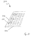
- FIGS. 21 to 24 show exemplary embodiments of a tube sheet with little material and thus associated with low material costs and low weight.
- the tube sheet 2010 in Fig. 21 has between the pipe receiving recesses 2020 with the pipe stop edges 2030 for material savings as openings 2040 formed recesses.
- the tube sheet 2110 in FIG Fig. 22 provided as side notches 2120 formed recesses.
- the tubesheet 2210 in FIGS. 23 and 24 is completely severed between the 2220 pipe receiving cutouts. In this case, the tubes 2230 may be stabilized only by the corrugated fins 2240.
- FIG. 14 shows another example of a wiring pattern of flow path portions of a heat exchanger 2310 accomplished by a configuration of passage and deflection passages 2320, 2330 of a baffle 2340.
- the flow path sections are in order 1 (down) - 2 (up) - 3 (down) - 4 (up) - 5 (down) - 6 (up) interconnected.
- a tube for each flow path section.
- a tube preferably contains two or more flow path sections, for example the flow path sections 1, 4 and 5 or the flow path sections 2, 3 and 6.
- flat tubes are particularly well suited for this purpose. Any further interconnection patterns of flow path sections are also conceivable over the ones shown.
- a heat exchanger in particular for a motor vehicle, with tubes which can be flowed through by a first medium in heat transfer channels and by a second medium, wherein the first medium can be conducted along at least one flow path composed of several sections, and with at least one end piece comprising a tube plate consisting of adjacent plates, wherein ends of the tubes with a bottom plate of the tubesheet is connectable, and wherein at least one deflection channel is formed by a recess in a baffle plate of the tube plate and with a cover plate can be closed in a fluid-tight manner with respect to an environment of the heat exchanger, wherein the at least one deflection channel connects the heat transfer channels of two flow path sections through which the first medium can flow successively, in particular according to predetermined criteria, wherein in particular the two interconnected flow path sections are arranged side by side in the main flow direction of the second medium in particular, the two interconnected flow path sections in the main flow direction of the second medium are aligned, wherein in particular the
- a heat exchanger in particular for a motor vehicle, with tubes which can be flowed through by a first medium in heat transfer channels and by a second medium, and with at least one end piece comprising a tube plate consisting of adjacent plates, wherein Ends of the tubes with a bottom plate of the tube sheet are connectable, and wherein at least one passage and / or deflection channel is formed by a recess in a baffle plate of the tube bottom and with a cover plate against an environment of the heat exchanger fluid-tightly closed, wherein a tube at a pipe end a recess and a pipe receiving the bottom plate has a web, wherein the recess and the web have a same width and in particular an equal height, in particular the recess has a greater height than the web, in particular the baffle with the Bod enplatte and / or formed integrally with the cover plate.
- a heat exchanger in particular for a motor vehicle, with tubes which can be flowed through by a first medium in heat transfer channels and by a second medium, and with at least one end piece comprising a tube plate consisting of adjacent plates, wherein Ends of the tubes are connectable to a bottom plate of the tube bottom, and wherein at least one passage and / or deflection channel is formed by a recess in a baffle plate of the tube bottom and with a cover plate against an environment of the heat exchanger fluid-tightly closed, wherein the bottom plate, the baffle and / or the cover plate are severed in areas between passage and / or deflection channels and / or have recesses in the form of openings or indentations, in particular, a tube is formed one or more times approximately U-shaped.
- a heat exchanger in particular for a motor vehicle, with tubes which can be flowed through by a first medium in heat transfer channels and by a second medium and with at least one end piece comprising a tube plate consisting of adjacent plates, wherein ends the tubes are connectable to a bottom plate of the tubesheet, and wherein at least one passage and / or deflection channel is formed by a recess in a baffle plate of the tube bottom and with a cover plate against an environment of the heat exchanger fluid-tightly closed, wherein at least one tube once or several times is deformed approximately U-shaped, in particular, the ends of the at least one deformed tube are connectable to the same bottom plate, in particular, the heat exchanger has exactly one end piece with a tube plate consisting of adjacent plates.
- a heat exchanger in particular for a motor vehicle, with tubes which are flowed through by a first medium in heat transfer channels and by a second medium and with exactly one end piece, which comprises a plate consisting of adjacent plates tube bottom, said ends the tubes are connectable to a bottom plate of the tube bottom, and wherein at least one passage and / or deflection channel is formed by a recess in a baffle plate of the tube bottom and with a cover plate against an environment of the heat exchanger fluid-tight closed, in particular the baffle plate with the bottom plate and / or soldered or welded to the cover plate, wherein in particular the bottom plate, the baffle plate and / or the cover plate at one edge of at least one opening has an extension which engages in an opening of an adjacent plate, insbeso the tubes are soldered or welded to the bottom plate, in particular, the tubes are designed as flat tubes, in particular with intermediate corrugated ribs.
- a refrigerant heat exchanger in particular evaporator for a motor vehicle air conditioning system consisting of flat tubes, which are flowed through by a liquid and / or vapor refrigerant, arranged between the flat tubes, acted upon by ambient air corrugated fins, from a collection and Distributor for the supply and the discharge of the refrigerant
- the collecting and distributing means consists of a plurality of stacked, perforated plates, whereby refrigerant channels are formed, wherein the ends of the flat tubes are held in receiving openings of a bottom plate and a deflection device for Deflection of the refrigerant in the flow direction of the ambient air
- the heat exchanger consists of a series of flat tubes, wherein in each case a flat tube two parallel flow sections, which flows through successively and verb over the deflection Andenen, wherein each flat tube end has a groove between the two flow sections in the middle of the flat tube end and wherein the bottom plate between
- a refrigerant heat exchanger in particular evaporator for motor vehicle air conditioners, consisting of flat tubes, which are flowed through by a liquid and / or vapor refrigerant, arranged between the flat tubes, acted upon by ambient air corrugated fins, from a collection and distribution device for Supply and discharge of the refrigerant
- the collecting and distributing means consists of a plurality of stacked, perforated plates, whereby refrigerant channels are formed, wherein the ends of the flat tubes are held in receiving openings of a bottom plate and a deflection device for deflecting the refrigerant in the flow direction of the ambient air
- the heat exchanger consists of a series of flat tubes, wherein in each case a flat tube two parallel flow sections, which flows through successively and the deflection device and wherein the collecting and distributing device has a calibrating device arranged between the refrigerant inlet and outlet, which is designed as a cover plate with calibration openings
Abstract
Description
Die Erfindung betrifft einen Wärmeübertrager mit Rohren und mit einem Endstück, das einen aus Platten bestehenden Rohrboden aufweist.The invention relates to a heat exchanger with pipes and with an end piece, which has a tube plate consisting of plates.
Ein solcher Wärmeübertrager ist beispielsweise in der
Man hat für einen ähnlichen Verdampfer in der
In der
Durch die
In der
Die Aufgabe der Erfindung ist es, einen Wärmeübertrager bereitzustellen, bei dem eine einfache und/oder leichte Bauweise und gegebenenfalls gleichzeitig eine gleichmäßige Verteilung eines Mediums auf mehrere Strömungspfade und/oder ein druckstabiler Aufbau des Wärmeübertragers realisierbar ist.The object of the invention is to provide a heat exchanger in which a simple and / or lightweight construction and optionally at the same time a uniform distribution of a medium to a plurality of flow paths and / or a pressure-stable construction of the heat exchanger can be realized.
Diese Aufgabe wird durch einen Wärmeübertrager mit den Merkmalen eines der nebengeordneten Ansprüche 1, 14, 26, 29, 31, 33 oder 36 gelöst.This object is achieved by a heat exchanger with the features of one of the
Gemäß dieser Ansprüche weist ein erfindungsgemäßer Wärmeübertrager Rohre auf, die von einem ersten Medium durchströmbar und von einem zweiten Medium umströmbar sind, so daß durch Wandungen der Rohre Wärme von dem ersten auf das zweite Medium oder umgekehrt übertragbar ist. Hierzu befinden sich in den Rohren Wärmeübertragungskanäle, durch die das erste Medium leitbar ist, wobei ein einzelnes Rohr entweder einen Wärmeübertragungskanal oder als sogenanntes Mehrkammerrohr mehrere nebeneinanderliegende Wärmeübertragungskanäle aufweist. Die Rohre können dabei einen kreisförmigen, einen ovalen, einen im wesentlichen rechteckförmigen oder einen beliebigen anderen Querschnitt besitzen. Beispielsweise sind die Rohre als Flachrohre ausgebildet. Für eine Erhöhung des Wärmeübertrags sind gegebenenfalls Rippen, insbesondere Wellrippen, zwischen den Rohren angeordnet, wobei die Rohre und die Rippen insbesondere miteinander verlötbar sind.According to these claims, a heat exchanger according to the invention on tubes which can be flowed through by a first medium and a second medium flow around, so that through walls of the tubes Heat from the first to the second medium or vice versa transferable. For this purpose, there are heat transfer channels in the tubes, through which the first medium can be conducted, wherein a single tube has either a heat transfer channel or as a so-called multi-chamber tube a plurality of adjacent heat transfer channels. The tubes may have a circular, an oval, a substantially rectangular or any other cross section. For example, the tubes are designed as flat tubes. For an increase in the heat transfer, optionally ribs, in particular corrugated fins, are arranged between the tubes, wherein the tubes and the ribs are in particular solderable to one another.
Für den Wärmeübertrager sind verschiedene Verwendungen denkbar, beispielsweise als Verdampfer eines Kältemittelkreislaufs, insbesondere einer Kraftfahrzeugklimaanlage. In diesem Fall ist das erste Medium ein Kältemittel, beispielsweise R134a oder R744, und das zweite Medium Luft, wobei Wärme von der Luft auf das Kältemittel übertragen wird. Der Wärmeübertrager ist aber auch für andere Medien geeignet, wobei gegebenenfalls die Wärme auch von dem ersten auf das zweite Medium übertragbar ist.For the heat exchanger various uses are conceivable, for example as an evaporator of a refrigerant circuit, in particular an automotive air conditioning system. In this case, the first medium is a refrigerant, for example, R134a or R744, and the second medium is air, whereby heat is transferred from the air to the refrigerant. The heat exchanger is also suitable for other media, where appropriate, the heat is also transferable from the first to the second medium.
Gegebenenfalls sind zumindest zwei Sammelkammern vorhanden, wobei das erste Medium von einer ersten zu einer zweiten Sammelkammer leitbar ist. Das erste Medium ist entlang eines oder mehrerer Strömungspfade leitbar, die gegebenenfalls aus mehreren Abschnitten bestehen. Unter einem Strömungspfadabschnitt im Sinne der Erfindung ist ein oder mehrere Wärmeübertragungskanäle zu verstehen, die von einer Seite des Wärmeübertragers zu einer gegenüberliegenden Seite verlaufen und hydraulisch parallel zueinander geschaltet sind. Die Wärmeübertragungskanäle eines Strömungspfadabschnittes sind beispielsweise in einem einzigen Rohr angeordnet, eine auf mehrere Rohre verteilte Anordnung der Wärmeübertragungskanäle eines Strömungspfadabschnittes ist jedoch ebenso denkbar.Optionally, at least two collection chambers are present, wherein the first medium can be conducted from a first to a second collection chamber. The first medium can be conducted along one or more flow paths, which optionally consist of several sections. A flow path section in the sense of the invention is to be understood as meaning one or more heat transfer channels which run from one side of the heat exchanger to an opposite side and are connected hydraulically in parallel to one another. The heat transfer channels of a flow path section are arranged, for example, in a single tube, one on several tubes However, distributed arrangement of the heat transfer channels of a flow path section is also conceivable.
Desweiteren weist der Wärmeübertrager ein Endstück mit einem Rohrboden auf, der aus aneinanderliegenden Platten, nämlich einer Bodenplatte, einer Umlenkplatte und einer Abdeckplatte besteht. Die Bodenplatte ist mit Enden der Rohre verbindbar, indem die Bodenplatte beispielsweise Aussparungen aufweist, in die die Rohrenden aufnehmbar sind. Im Rahmen der Erfindung sind auch andere Arten der Verbindung zwischen Rohren und der Bodenplatte denkbar, zum Beispiel durch Fortsätze an den Rändern von Aussparungen in der Bodenplatte, so daß die Rohre auf die Fortsätze aufsteckbar sind. Aussparungen in der Umlenkplatte dienen der Bildung von Durchleitkanälen und/oder von Umlenkkanälen, die gegenüber einer Umgebung des Wärmeübertragers mit einer Abdeckplatte fluiddicht verschließbar sind. Durch die Plattenstruktur des Rohrbodens ist eine sehr druckstabile Bauweise des Endstücks und des gesamten Wärmeübertragers möglich.Furthermore, the heat exchanger has an end piece with a tube plate, which consists of adjacent plates, namely a bottom plate, a baffle plate and a cover plate. The bottom plate is connectable to ends of the tubes by the bottom plate, for example, has recesses into which the pipe ends are receivable. In the context of the invention, other types of connection between pipes and the bottom plate are conceivable, for example, by extensions at the edges of recesses in the bottom plate, so that the tubes are attachable to the extensions. Recesses in the deflection plate serve for the formation of passage channels and / or deflection channels, which can be closed fluid-tight with respect to an environment of the heat exchanger with a cover plate. Due to the plate structure of the tube plate a very pressure-stable construction of the tail and the entire heat exchanger is possible.
Ein erster Grundgedanke der Erfindung ist es, das den Rohrboden umfassende Endstück mit einem Sammelkasten zu versehen, der in einem Gehäuse zumindest eine Sammelkammer für das erste Medium aufweist. Dadurch wird ein gegebenenfalls ohnehin notwendiges Bauteil in das Endstück integriert und eine kompakte und damit einfache Bauweise des Wärmeübertragers gewährleistet.A first basic idea of the invention is to provide the end piece comprising the tubesheet with a collection box which has at least one collection chamber for the first medium in a housing. As a result, an optionally necessary anyway component is integrated into the tail and ensures a compact and therefore simple construction of the heat exchanger.
Gemäß eines zweiten Grundgedankens der Erfindung werden Strömungspfadabschnitte mittels Umlenkkanälen in der Umlenkplatte miteinander verbunden. Die Verschaltung der Strömungspfadabschnitte zu einem oder mehreren hydraulisch parallelen Strömungspfaden ist dann nach beliebigen Anforderungen auslegbar, indem eine einzige Platte, nämlich die Umlenkplatte, entsprechend der erforderlichen Strömungspfadverschaltung konfiguriert wird. Somit ist der Wärmeübertrager durch seine modulare Bauweise für verschiedene Anwendungen flexibel aufbaubar.According to a second basic concept of the invention, flow path sections are connected to one another by means of deflection channels in the deflection plate. The interconnection of the flow path sections to one or more hydraulically parallel flow paths can then be interpreted according to any requirements by a single plate, namely the baffle plate, corresponding to the required flow path connection is configured. Thus, the heat exchanger can be built flexibly for various applications due to its modular design.
Nach einem anderen Grundgedanken der Erfindung wird ein Rohr bis zu einem vorgegebenem Anschlag in den Rohrboden eingeführt, um eine erhöhte Fertigungssicherheit und damit eine vereinfachte Herstellung zu erzielen. Der Anschlag wird durch einen Steg zwischen zwei Aussparungen in der Bodenplatte verwirklicht, der in eine Aussparung in einem Rohrende aufnehmbar ist, wobei der Steg im wesentlichen genauso breit ist wie die Aussparung in dem Rohrende. Vorteilhafterweise ist die Aussparung etwas breiter als der Steg, um ein Einstecken des Rohres in die Bodenplatte zu erleichtern. Die Einstecktiefe des Rohres ist durch die Höhe der Aussparung in dem Rohrende gegeben. Besonders vorteilhaft ist die Aussparung höher als der Steg, wodurch die Gefahr einer ungewünschten Verstopfung eines oder mehrerer Wärmeübertragungskanäle durch auf der Bodenplatte befindliches Lot während eines. Lötprozesses verringert wird. Der Höhenunterschied ist beispielsweise 1 mm oder mehr, sollte andererseits geringer sein als die Dicke der Umlenkplatte, da das Rohr sonst an die Abdeckplatte anstößt. Vorteilhaft ist ein Höhenunterschied, der in etwa halb so groß ist wie die Dicke der Umlenkplatte.According to another basic idea of the invention, a tube is introduced into the tubesheet up to a predetermined stop in order to achieve increased manufacturing reliability and thus simplified production. The stop is realized by a web between two recesses in the bottom plate, which is receivable in a recess in a pipe end, wherein the web is substantially as wide as the recess in the pipe end. Advantageously, the recess is slightly wider than the web to facilitate insertion of the tube into the bottom plate. The insertion depth of the tube is given by the height of the recess in the pipe end. Particularly advantageously, the recess is higher than the web, whereby the risk of unwanted clogging of one or more heat transfer channels by solder located on the bottom plate during a. Soldering process is reduced. The height difference is, for example, 1 mm or more, on the other hand, should be less than the thickness of the baffle, since the pipe otherwise abuts the cover plate. Advantageously, a height difference that is about half as large as the thickness of the baffle plate.
Ein weiterer Grundgedanke der Erfindung ist es, mehrere Platten des Rohrbodens einstückig zu gestalten, um die Anzahl den Fertigungs- und gegebenenfalls den Materialaufwand zu reduzieren. Unter Umständen besteht der Rohrboden dann nur aus einer Platte, in die die Bodenplatte, die Umlenkplatte und die Abdeckplatte integriert sind.Another basic idea of the invention is to design a plurality of plates of the tubesheet in one piece in order to reduce the number of production and, if necessary, the cost of materials. Under certain circumstances, the tube plate then only consists of a plate in which the bottom plate, the baffle plate and the cover plate are integrated.
Gemäß eines weiteren Erfindungsgedankens wird der Materialaufwand für den Rohrboden und damit auch für den Wärmeübertrager reduziert, indem eine oder mehrere, bevorzugt alle Platten des Rohrbodens zusätzliche Aussparungen zwischen Durchleit- und/oder Umlenkkanälen aufweisen, die beispielsweise als Durchbrüche oder seitliche Einkerbungen ausgebildet sind. Vorteilhaft sind die Platten zwischen Durchleit- und/oder Umlenkkanälen durchtrennt, wodurch die Platten unter Umständen in viele kleine Teilplatten zerfallen. Dadurch wird eine besonders leichte Bauweise ermöglicht, die sich auf Materialkosten und Gewicht des Wärmeübertragers gleichermaßen positiv auswirkt.According to a further concept of the invention, the cost of materials for the tube plate and thus also for the heat exchanger is reduced by one or more, preferably all plates of the tubesheet have additional recesses between passage and / or deflection channels, the For example, as breakthroughs or lateral indentations are formed. Advantageously, the plates are severed between passage and / or deflection channels, whereby the plates may disintegrate into many small sub-plates. This allows a particularly lightweight construction, which has a positive effect on material costs and weight of the heat exchanger alike.
Eine vereinfachte Bauweise wird nach einem weiteren Grundgedanken der Erfindung auch durch U-förmig umgeformte Rohre ermöglicht, wobei die Rohre einfach oder zu einer noch einfacheren Bauweise mehrfach umgeformt sind. Dadurch wird im Bereich der U-förmigen Umformung zwei Rohr-Boden-Verbindungen und gegebenenfalls ein Umlenkkanal eingespart. Bei ausschließlicher Verwendung von U-Rohren ist es sogar möglich, ein Endstück einzusparen, wenn auf einer Seite des Wärmeübertragers sämtliche Umlenkungen durch Rohrumformungen verwirklicht sind. In diesem Fall sind die Enden jeweils eines Rohres mit derselben Bodenplatte verbindbar.A simplified construction is made possible according to a further basic idea of the invention by U-shaped tubes, wherein the tubes are simply or repeatedly formed into an even simpler construction. As a result, in the region of the U-shaped deformation, two pipe-floor connections and optionally a deflection channel are saved. With the exclusive use of U-tubes, it is even possible to save an end piece, if on one side of the heat exchanger all deflections are realized by Rohrumformungen. In this case, the ends of each tube are connectable to the same bottom plate.
Ein weiterer Erfindungsgedanke ist es, den Wärmeübertrager mit genau einem Endstück zu versehen, in das insbesondere ein Sammelkasten mit zwei Sammelkammern integriert ist. Dies ist außer durch Verwendung von U-Rohren durch jede denkbare hydraulische Verbindung von Rohren auf einer dem genau einen Endstück gegenüberliegenden Seite des Wärmeübertragers möglich, beispielsweise durch Aufsetzen von geeignet aufgebauten Kappen auf jeweils mehrere, insbesondere zwei Rohre.Another idea of the invention is to provide the heat exchanger with exactly one end piece, in which in particular a collecting box is integrated with two collecting chambers. This is possible except through the use of U-tubes through any conceivable hydraulic connection of pipes on a side opposite exactly one end of the heat exchanger, for example by placing suitably constructed caps on a plurality of, in particular two tubes.
Bevorzugte Ausführungsformen des erfindungsgemäßen Wärmeübertragers sind Gegenstand der untergeordneten Ansprüche.Preferred embodiments of the heat exchanger according to the invention are the subject of the subordinate claims.
Gemäß einer bevorzugten Ausführungsform ist ein gegebenenfalls in das Endstück integrierter Sammelkasten mit der Abdeckplatte fluiddicht verlötet oder verschweißt. Nach einer anderen vorteilhaften Ausführungsform ist der Sammelkasten mit der Abdeckplatte einstückig ausgebildet, wodurch die Fertigung vereinfacht wird. Eine besonders leichte Bauweise wird durch eine rohrförmige Ausbildung des Sammelkastens gemäß einer weiteren Ausgestaltung der Erfindung erreicht. Besonders bevorzugt weist die Abdeckplatte an Rändern von Durchbrüchen Fortsätze auf, die in Durchbrüche eines Gehäuses des Sammelkastens eingreifen. Umgekehrt ist es nach einer weiteren Ausführungsform möglich, Durchbrüche des Samrnelkastengehäuses mit Fortsätzen zu versehen, die in Durchbrüche der Abdeckplatte eingreifen. In beiden Fällen ist die Fertigungssicherheit durch eine Ausrichtung der miteinander fluchtenden Durchbrüche in der Abdeckplatte und in dem Sammelkastengehäuse erhöht.According to a preferred embodiment, an optionally integrated into the tail collecting tank with the cover plate is soldered fluid-tight or welded. According to another advantageous embodiment of the collecting box is integrally formed with the cover plate, whereby the production is simplified. A particularly lightweight design is achieved by a tubular design of the collecting tank according to a further embodiment of the invention. Particularly preferably, the cover plate on edges of openings on extensions which engage in openings of a housing of the collecting tank. Conversely, it is possible according to a further embodiment, to provide apertures of the Samrnelkastengehäuses with extensions which engage in openings of the cover plate. In both cases, the manufacturing safety is increased by an alignment of the mutually aligned openings in the cover plate and in the collection box housing.
Gemäß einer bevorzugten Ausführungsform weisen die Durchtrittsöffnungen, die durch die miteinander fluchtenden Durchbrüche in der Abdeckplatte und in dem Sammelkastengehäuse gebildet werden, unterschiedliche Strömungsquerschnitte auf. Dadurch wird auf einfache Weise eine Anpassung der Verteilung des ersten Mediums an die Strömungsverhältnisse in der zugehörigen Sammelkammer ermöglicht. Insbesondere eine gleichmäßige Verteilung auf mehrere Strömungspfade ist dabei erstrebenswert, wobei aber auch eine bewußt ungleichmäßige Verteilung denkbar ist, beispielsweise bei ungleichmäßigem Massenstrom des zweiten Mediums über eine Stirnfläche des Wärmeübertragers. Vorteilhafterweise sind die Durchtrittsöffnungen mit unterschiedlichen Strömungsquerschnitten stromaufwärts der Wärmeübertragungskanäle angeordnet, wodurch die Strömung in den Strömungspfaden besonders einfach ausgleichbar ist. Wenn Durchströmmengen durch die Strömungspfade auf einer Eintrittsseite für das erste Medium geregelt werden, sind die Durchtrittsöffnungen auf der Austrittsseite größer gestaltbar, beispielsweise mit einem Strömungsquerschnitt, der dem Strömungsquerschnitt des jeweiligen Strömungspfades entspricht. Wird der Wärmeübertrager beispielsweise als Verdampfer in einem Kältemittelkreislauf verwendet, sind die Druckverhältnisse entlang des Kreislaufs vorteilhafter für die Leistungsfähigkeit des Wärmeübertragers, wenn Strömungsquerschnitte vor einer Erwärmung des Kältemittels eingeengt sind, als bei einer Einengung der Strömungsquerschnitte nach der Erwärmung.According to a preferred embodiment, the passage openings, which are formed by the mutually aligned openings in the cover plate and in the collection box housing, have different flow cross-sections. As a result, an adaptation of the distribution of the first medium to the flow conditions in the associated collection chamber is made possible in a simple manner. In particular, a uniform distribution over a plurality of flow paths is desirable, but also a deliberately uneven distribution is conceivable, for example, at uneven mass flow of the second medium over an end face of the heat exchanger. Advantageously, the passage openings are arranged with different flow cross-sections upstream of the heat transfer channels, whereby the flow in the flow paths is particularly easily compensated. If flow rates through the flow paths are regulated on an inlet side for the first medium, the passage openings on the outlet side can be made larger, for example with a flow cross section which corresponds to the flow cross section of the respective flow path. Will the Heat exchangers, for example, used as an evaporator in a refrigerant circuit, the pressure conditions along the circuit are more advantageous for the performance of the heat exchanger when flow cross sections are narrowed before heating the refrigerant, as in a narrowing of the flow cross sections after heating.
Die Strömungsquerschnitte der Durchtrittsöffnungen sind gemäß einer Ausgestaltung an eine Druckverteilung des ersten Mediums innerhalb der betreffenden Sammelkammer anpaßbar. Bei einer anderen Ausgestaltung sind die Strömungsquerschnitte an eine Dichteverteilung des ersten Mediums innerhalb der betreffenden Sammelkammer anpaßbar. Unter der Dichte eines Mediums im Sinne der Erfindung ist bei einphasigen Medien die physikalische Dichte zu verstehen, während bei mehrphasigen Medien, beispielsweise bei Medien, die teilweise flüssig und teilweise gasförmig vorliegen, eine über das jeweils betreffende Volumen gemittelte Dichte zu verstehen ist.The flow cross-sections of the passage openings are adaptable according to an embodiment of a pressure distribution of the first medium within the respective collection chamber. In another embodiment, the flow cross sections can be adapted to a density distribution of the first medium within the respective collection chamber. For the purposes of the invention, the density of a medium is to be understood as the physical density in single-phase media, while in the case of multiphase media, for example in media which are partly liquid and partly gaseous, a density averaged over the volume in question is to be understood.
Aus ähnlichen Gründen sind die Querschnittsflächen der ersten und der zweiten Sammelkammer bei einer bevorzugten Ausführung voneinander verschieden. Besonders bevorzugt sind die Querschnittsflächen der Sammelkammern an die Dichteverhältnisse des ersten Mediums in den Kammern anpaßbar.For similar reasons, the cross sectional areas of the first and second plenums are different from one another in a preferred embodiment. Particularly preferably, the cross-sectional areas of the collecting chambers can be adapted to the density ratios of the first medium in the chambers.
Weitere Ausführungformen des erfindungsgemäßen Wärmeübertragers beziehen sich auf die Verschaltung der Strömungspfadabschnitte mittels Umlenkkanälen in der Umlenkplatte.Further embodiments of the heat exchanger according to the invention relate to the interconnection of the flow path sections by means of deflection channels in the deflection plate.
Gemäß einer vorteilhaften Ausgestaltung werden durch einen Umlenkkanal Strömungspfadabschnitte miteinander verbunden, die in Hauptströmungsrichtung des zweiten Mediums nebeneinander angeordnet sind. Man spricht dann von einer Umlenkung in der Breite. Dadurch ist es möglich, mehrere oder eventuell alle Strömungspfadabschnitte innerhalb einer Reihe beziehungsweise innerhalb einer Rohrreihe miteinander zu einem Strömungspfad zu verbinden. Dies führt zu einer zumindest teilweisen Serpentinenbauweise des Wärmeübertragers. Bei einer anderen Ausgestaltung fluchten die miteinander verbundenen Strömungspfadabschnitte in Hauptströmungsrichtung des zweiten Mediums. Man spricht dann von einer Umlenkung in der Tiefe. Dadurch ist es möglich, Strömungspfade für das erste Medium parallel oder antiparallel zur Hauptströmungsrichtung des zweiten Mediums zu verschalten. Dies führt zu einer zumindest teilweisen Gegenstrombauweise des Wärmeübertragers.According to an advantageous embodiment, flow path sections which are arranged side by side in the main flow direction of the second medium are connected to one another by a deflection channel are. One speaks then of a deflection in the width. This makes it possible to connect several or possibly all flow path sections within a row or within a row of pipes together to form a flow path. This leads to an at least partial serpentine construction of the heat exchanger. In another embodiment, the interconnected flow path sections are aligned in the main flow direction of the second medium. One speaks then of a deflection in the depth. This makes it possible to connect flow paths for the first medium parallel or antiparallel to the main flow direction of the second medium. This leads to an at least partial countercurrent construction of the heat exchanger.
Gemäß einer weiteren Ausführungsform werden durch einen Umlenkkanal zwei Strömungspfadabschnitte innerhalb eines Rohres miteinander verbunden. Das bedeutet, daß das erste Medium in einer Richtung durch das Rohr strömt und in Gegenrichtung durch dasselbe Rohr zurückströmt. Durch eine Verwendung von Rohren mit vielen Wärmeübertragungskanälen wird so die Gesamtanzahl der Rohre und damit der Fertigungsaufwand verringert.According to a further embodiment, two flow path sections are interconnected within a tube by a deflection channel. This means that the first medium flows in one direction through the tube and flows back in the opposite direction through the same tube. By using pipes with many heat transfer channels so the total number of tubes and thus the manufacturing cost is reduced.
Gemäß einer bevorzugten Ausgestaltung ist die Anzahl der Abschnitte zumindest eines Strömungspfades durch zwei teilbar. Dies bedeutet, daß eine zweireihige Anordnung der Strömungspfadabschnitte einfach verschaltbar ist, indem die erste Hälfte der Abschnitte eines Strömungspfades in einer ersten Reihe angeordnet und durch Umlenkungen in der Breite miteinander verbunden ist, wohingegen die zweite Hälfte der Abschnitte in einer zweiten Reihe angeordnet und ebenfalls durch Umlenkungen in der Breite miteinander verbunden ist, wobei die beiden Hälften des Strömungspfades durch eine Umlenkung in der Tiefe verbunden sind. Diese Umlenkung in der Tiefe geschieht beispielsweise in einem Umlenkkanal einer Umlenkplatte eines Rohrbodens auf oder den Sammelkammern gegenüberliegenden Seite des Wärmeübertragers. Besonders bevorzugt ist die Anzahl der Abschnitte des Strömungspfades durch vier teilbar. Dies bedeutet, daß bei einer zweireihigen Anordnung der Strömungspfadabschnitte mit der oben beschriebenen Verschaltung die Umlenkung in der Tiefe auf der Seite des Wärmeübertragers geschieht, auf der sich auch die Sammelkammern befinden. Dadurch ist nur eine Umlenkplatte des Wärmeübertragers zu konfigurieren, wenn der Wärmeübertrager für vorgegebene Anforderungen ausgelegt wird, während andere Bauteile unverändert übernommen werden.According to a preferred embodiment, the number of sections of at least one flow path is divisible by two. This means that a two-row arrangement of the flow path sections is easily interconnected by the first half of the sections of a flow path arranged in a first row and connected by deflections in the width, whereas the second half of the sections arranged in a second row and also through Deflections in the width is connected to each other, wherein the two halves of the flow path are connected by a deflection in the depth. This deflection in depth is done for example in a deflection of a baffle plate of a tube plate or the Collection chambers opposite side of the heat exchanger. Particularly preferably, the number of sections of the flow path is divisible by four. This means that in a double-row arrangement of the flow path sections with the above-described interconnection, the deflection takes place in the depth on the side of the heat exchanger on which the collection chambers are located. As a result, only one baffle of the heat exchanger is to be configured when the heat exchanger is designed for given requirements, while other components are taken over unchanged.
Bei einer Ausgestaltung werden die ersten und letzten Strömungspfadabschnitte innerhalb einer oder mehrerer Rohrreihen nicht als hydraulisch erste Abschnitte von Strömungspfaden beaufschlagt, da im Randbereich von Sammelkammern, die üblicherweise entlang Rohrreihen angeordnet sind, die Strömungs- und/oder Druckverhältnisse des ersten Mediums ungünstig für eine Beaufschlagung von Strömungspfaden sind.In one embodiment, the first and last flow path sections within one or more rows of tubes are not acted upon as hydraulically first sections of flow paths, since the flow and / or pressure conditions of the first medium are unfavorable for application in the edge region of collection chambers, which are usually arranged along rows of tubes of flow paths are.
Gemäß einer vorteilhaften Ausführung verlaufen zwei benachbarte Strömungspfade spiegelsymmetrisch zueinander. Besonders bevorzugt kommunizieren Umlenkkanäle zumindest zweier Strömungspfade. Dadurch wird innerhalb der Strömungspfade ein zusätzlicher Ausgleich der Durchströmung bewirkt. Bei einem spiegelsymmetrischen Verlauf der miteinander kommunizierenden Strömungspfade ist eine Kommunikation der dann gegebenenfalls benachbarten Umlenkkanäle besonders einfach zu bewerkstelligen, beispielsweise durch ein Weglassen eines Steges, der unter Umständen ansonsten zwischen zwei Umlenkkanälen vorhanden ist.According to an advantageous embodiment, two adjacent flow paths are mirror-symmetrical to each other. Particularly preferably, deflection channels communicate at least two flow paths. As a result, an additional compensation of the flow is effected within the flow paths. In the case of a mirror-symmetrical course of the flow paths communicating with one another, it is particularly easy to communicate the optionally adjacent deflection channels, for example by omitting a web which may otherwise be present between two deflection channels.
Bei einer weiteren bevorzugten Ausführung ändert sich ein Strömungsquerschnitt eines Strömungspfades während seines Verlaufes. Dies ist sehr einfach zu verwirklichen, indem beispielsweise Strömungspfadabschnitte mit wenigen Wärmeübertragungskanälen über entsprechend konfigurierte Umlenkkanäle mit Strömungspfadabschnitten mit vielen Wärmeübertragungskanälen verbunden werden. Besonders bevorzugt ist eine Anpassung des Strömungsquerschnitts eines Strömungspfades an eine sich entlang des Strömungspfades ändernde Dichte des ersten Mediums.In a further preferred embodiment, a flow cross section of a flow path changes during its course. This is very easy to realize, for example, by flow path sections with few heat transfer channels over correspondingly configured deflection channels with flow path sections are connected to many heat transfer channels. An adaptation of the flow cross section of a flow path to a density of the first medium changing along the flow path is particularly preferred.
Vorteilhaft ist eine Ausgestaltung, bei der alle Abschnitte zumindest eines Strömungspfades in Hauptströmungsrichtung des zweiten Mediums miteinander fluchten. Besonders vorteilhaft sind alle Strömungspfade des Wärmeübertragers in dieser Weise ausgebildet, wodurch eine reine Gegenstrombauweise des Wärmeübertragers auf einfache Weise, nämlich durch entsprechend konfigurierte Umlenkkanäle in einer Umlenkplatte, ermöglicht wird.An embodiment is advantageous in which all sections of at least one flow path in the main flow direction of the second medium are aligned with one another. Particularly advantageously, all flow paths of the heat exchanger are formed in this manner, whereby a pure countercurrent construction of the heat exchanger in a simple manner, namely by appropriately configured deflection channels in a baffle is possible.
Bei einer weiteren Ausführungsform besteht der Wärmeübertrager aus Flachrohren, die von einem flüssigen und/oder dampfförmigen Kältemittel durchströmt werden, zwischen den Flachrohren angeordneten, von Umgebungsluft beaufschlagten Wellrippen, einer Sammel- und Verteileinrichtung für die Zufuhr und die Abfuhr des Kältemittels, wobei die Sammel- und Verteileinrichtung aus einer Mehrzahl von übereinander geschichteten, durchbrochenen Platten besteht, wodurch Kältemittelkanäle gebildet werden, wobei die Enden der Flachrohre in Aufnahmeöffnungen einer Bodenplatte gehalten sind und einer Umlenkeinrichtung zur Umlenkung des Kältemittels in Strömungsrichtung der Umgebungsluft, und wobei der Wärmeübertrager aus einer Reihe von Flachrohren besteht, wobei jeweils ein Flachrohr zwei parallel verlaufende Strömungsabschnitte, die nacheinander durchströmt und über die Umlenkeinrichtung verbunden sind, aufweist, wobei jedes Flachrohr endseitig eine Nut zwischen den beiden Strömungsabschnitten in der Mitte des Flachrohrendes aufweist und daß die Bodenplatte zwischen den Aufnahmeöffnungen Stege aufweist, die in ihren Abmessungen bezüglich Höhe und Breite den Nuten entsprechen und mit den Nuten jeweils eine Fügeverbindung bilden.In a further embodiment, the heat exchanger consists of flat tubes through which a liquid and / or vapor refrigerant flows, corrugated fins exposed to ambient air, a collection and distribution device for the supply and removal of the refrigerant, arranged between the flat tubes. and distribution means consists of a plurality of stacked, perforated plates, whereby refrigerant channels are formed, the ends of the flat tubes are held in receiving openings of a bottom plate and a deflection device for deflecting the refrigerant in the direction of flow of ambient air, and wherein the heat exchanger from a series of flat tubes each one flat tube has two parallel flow sections, which flows through one after the other and are connected via the deflection, wherein each flat tube end a groove between the two flow Sections in the middle of the flat tube end and that the bottom plate between the receiving openings webs, which in terms of their dimensions Height and width correspond to the grooves and each form a joint connection with the grooves.
Besonders bevorzugt wird die Umlenkeinrichtung durch eine weitere Bodenplatte mit Aufnahmeöffnungen und Stegen gebildet, die mit der endseitigen Nut der Flachrohre eine Fügeverbindung bilden.Particularly preferably, the deflection device is formed by a further base plate with receiving openings and webs, which form a joint connection with the end-side groove of the flat tubes.
Besonders bevorzugt weist die Umlenkeinrichtung zusätzlich eine Kanalplatte mit durchgehenden Schlitzen und eine geschlossene Abdeckplatte auf.Particularly preferably, the deflection device additionally has a channel plate with through slots and a closed cover plate.
Besonders bevorzugt weist die Sammel- und Verteileinrichtung eine Kanalplatte mit Kanalöffnungen und Stegen zwischen den Kanalöffnungen, eine Abdeckplatte mit Kältemitteleintritts- und -austrittsöffnungen und einen Kältemittel-Zufuhr- und einen Kältemittel-Abfuhrkanal, die parallel zueinander und in Längsrichtung des Wärmeübertragers angeordnet sind, auf, wobei die Bodenplatte, die Kanalplatte und die Abdeckplatte derart übereinander angeordnet sind, daß die Öffnungen in den Platten mit den Flachrohrenden fluchten.Particularly preferably, the collecting and distributing device has a channel plate with channel openings and webs between the channel openings, a cover plate with refrigerant inlet and -austrittsöffnungen and a refrigerant supply and a refrigerant discharge channel, which are arranged parallel to each other and in the longitudinal direction of the heat exchanger on wherein the bottom plate, the channel plate and the cover plate are arranged one above the other in such a way that the openings in the plates are aligned with the flat tube ends.
Besonders bevorzugt sind die Kältemitteleintrittsöffnungen als kalibrierte Bohrungen ausgebildet, wobei der Durchmesser der Bohrungen insbesondere variabel ist. Ebenfalls bevorzugt sind die Abdeckplatte sowie die Kältemittelzufuhr- und -abfuhrkanäle einstückig ausgebildet.Particularly preferably, the refrigerant inlet openings are formed as calibrated bores, wherein the diameter of the bores is in particular variable. Also preferably, the cover plate and the refrigerant supply and -abfuhrkanäle are integrally formed.
Gemäß einer weiteren Ausgestaltungsform besteht der Wärmeübertrager, der insbesondere als Verdampfer für Kraftfahrzeugklimaanlagen verwendbar ist, aus Flachrohren, die von einem flüssigen und/oder dampfförmigen Kältemittel durchströmt werden, zwischen den Flachrohren angeordneten, von Umgebungsluft beaufschlagten Wellrippen, einer Sammel- und Verteileinrichtung für die Zufuhr und die Abfuhr des Kältemittels, wobei die Sammel- und Verteileinrichtung aus einer Mehrzahl von übereinander geschichteten, durchbrochenen Platten besteht, wodurch Kältemittel-Kanäle gebildet werden, wobei die Enden der Flachrohre in Aufnahmeöffnungen einer Bodenplatte gehalten sind, und einer Umlenkeinrichtung zur Umlenkung des Kältemittels in Strömungsrichtung der Umgebungsluft. Der Wärmeübertrager besteht dabei aus einer Reihe von Flachrohren, wobei jeweils ein Flachrohr zwei parallel verlaufende Strömungsabschnitte, die nacheinander durchströmbar und über die Umlenkeinrichtung verbunden sind, aufweist und wobei die Sammel- und Verteileinrichtung eine zwischen Kältemitteleintritt und -austritt angeordnete Kalibriereinrichtung aufweist, die als Abdeckplatte mit Kalibrieröffnungen für die Kältemittelverteilung ausgebildet ist. Bevorzugt sind die Kalibrieröffnungen auf der Kältemitteleintrittsseite angeordnet.According to a further embodiment of the heat exchanger, which is particularly useful as an evaporator for motor vehicle air conditioners, consisting of flat tubes, which are flowed through by a liquid and / or vapor refrigerant, arranged between the flat tubes, acted upon by ambient air corrugated fins, a collecting and distributing device for the supply and the removal of the refrigerant, wherein the Collection and distribution device consists of a plurality of stacked, perforated plates, whereby refrigerant channels are formed, wherein the ends of the flat tubes are held in receiving openings of a bottom plate, and a deflection device for deflecting the refrigerant in the flow direction of the ambient air. The heat exchanger consists of a series of flat tubes, wherein in each case a flat tube two parallel flow sections, which are successively flowed through and connected via the deflection, and wherein the collecting and distributing device has a between refrigerant inlet and outlet arranged calibration device, which serves as a cover plate is formed with calibration openings for the refrigerant distribution. Preferably, the calibration openings are arranged on the refrigerant inlet side.
Gemäß einer vorteilhaften Weiterbildung weisen die Kalibrieröffinungen unterschiedliche Strömungsquerschnitte auf. Bevorzugt werden die Strömungsquerschnitte der Kalibrieröffnungen in Richtung des Druckabfalles des Kältemittels im Zufuhrkanal größer. Besonders bevorzugt sind die Strömungsquerschnitte der Kalibrieröffnungen in Abhängigkeit vom spezifischen Volumen des Kältemittels bzw. dessen Dampfgehalt variabel.According to an advantageous development, the calibration openings have different flow cross sections. The flow cross sections of the calibration openings are preferably larger in the direction of the pressure drop of the refrigerant in the feed channel. Particularly preferably, the flow cross sections of the calibration openings are variable depending on the specific volume of the refrigerant or its vapor content.
Bei einer anderen Ausführungsform des Wärmeübertragers sind die Flachrohre als Serpentinensegmente ausgebildet und die Umlenkeinrichtung in der Sammel- und Verteileinrichtung angeordnet.In another embodiment of the heat exchanger, the flat tubes are designed as serpentine segments and the deflection device is arranged in the collecting and distributing device.
Gemäß einer weiteren Ausgestaltung weist die Sammel- und Verteileinrichtung eine Kanalplatte mit durchgehenden Kanalöffnungen zur Umlenkung des Kältemittels und Kanalöffnungen mit Stegen, eine Abdeckplatte mit Kältemitteleintitts- und Austrittsöffnungen und einen Kältemittelzufuhr- und einen Kältemittelabfuhrkanal auf. Die Kanalöffnungen mit Stegen sind dabei jeweils mit dem ersten Flachrohrende des Serpentinensegments fluchtend angeordnet, wohingegen die durchgehenden Kanalöffnungen mit dem zweiten Flachrohrende des Serpentinensegments fluchtend angeordnet sind, wobei die Kältemittelein- und -austrittsöffnungen mit den Kanalöffnungen fluchten und die durchgehenden Kanalöffnungen durch die Abdeckplatte abgedeckt sind. Bevorzugt weisen die Serpentinensegmente zwei oder drei Umlenkungen in der Breite auf.According to a further embodiment, the collecting and distributing device has a channel plate with through-channel openings for deflecting the refrigerant and channel openings with webs, a cover plate with refrigerant inlet and outlet openings and a refrigerant supply and a refrigerant discharge channel. The channel openings with webs are in each case with the first flat tube end of the Serpentine segment arranged in alignment, whereas the through-channel openings are arranged in alignment with the second flat tube end of the serpentine segment, wherein the refrigerant inlet and -austrittsöffnungen are aligned with the channel openings and the through-channel openings are covered by the cover plate. Preferably, the serpentine segments have two or three deflections in width.
Gemäß einer vorteilhaften Ausführungsform des Wärmeübertragers sind die Flachrohre als U-Rohre, das heißt mit je einer Umlenkung (in der Breite) ausgebildet. Besonders bevorzugt sind jeweils zwei U-Rohre kältemittelseitig hintereinander geschaltet, und jeweils zwei benachbarte Kanalöffnungen, die einem U-Rohrauslaß und einem U-Rohreinlaß zugeordnet sind, stehen durch einen Querkanal in der Kanalplatte miteinander in Kältemittelverbindung.According to an advantageous embodiment of the heat exchanger, the flat tubes are designed as U-tubes, that is, each with a deflection (in width). Two U-tubes are particularly preferably connected in series on the refrigerant side, and two adjacent channel openings, which are assigned to a U-tube outlet and a U-tube inlet, are in refrigerant communication with each other through a transverse channel in the channel plate.
Bevorzugt ist die Breite b der Kanalöffnungen in der Kanalplatte größer als die Breite a der Aufnahmeöffnungen in der Bodenplatte. Ebenfalls vorteilhaft ist die Tiefe der Nut in den Flachrohrenden größer als die Dicke der Bodenplatte.Preferably, the width b of the channel openings in the channel plate is greater than the width a of the receiving openings in the bottom plate. Also advantageously, the depth of the groove in the flat tube ends is greater than the thickness of the bottom plate.
Vorteilhafterweise treffen auf den Wärmeübertrager eine oder mehrere der folgenden Maßangaben zu:
Die Erfindung wird nachfolgend anhand von Ausführungsbeispielen unter Bezugnahme auf die Zeichnungen näher erläutert. Es zeigen:
- Fig. 1
- einen Parallelstromverdampfer in Explosivdarstellung,
- Fig. 2
- einen Verdampfer mit Serpentinensegment (Umlenkung in der Breite),
- Fig. 3
- einen Verdampfer mit U-Rohren,
- Fig. 4
- einen Schnitt IV-IV durch Verdampfer gemäß
Fig. 3 , - Fig. 5
- einen Schnitt V-V durch Verdampfer gemäß
Fig. 3 , - Fig. 6
- einen Verdampfer mit hintereinandergeschalteten U-Rohren (Umlenkung in der Breite),
- Fig. 7
- einen Wärmeübertrager in Querschnittsdarstellung,
- Fig. 8
- einen Wärmeübertrager in einer Teilansicht,
- Fig. 9
- einen Wärmeübertrager in einer Teilansicht,
- Fig. 10
- eine Umlenkplatte,
- Fig. 11
- einen Rohrboden in einer Teilansicht,
- Fig. 12
- einen Rohrboden in Explosivdarstellung,
- Fig. 13
- einen Rohrboden in Querschnittsdarstellung,
- Fig. 14
- einen Rohrboden in Längsschnittsdarstellung,
- Fig. 15
- einen Rohrboden,
- Fig. 16
- einen Rohrboden in Querschnittsdarstellung,
- Fig. 17
- einen Wärmeübertrager in einer Teilansicht,
- Fig. 18
- einen Rohrboden in Querschnittsdarstellung,
- Fig. 19
- einen Rohrboden,
- Fig. 20
- einen Rohrboden,
- Fig. 21
- einen Rohrboden,
- Fig. 22
- einen Rohrboden,
- Fig. 23
- einen Rohrboden,
- Fig. 24
- einen Wärmeübertrager in einer Teilansicht und
- Fig. 25
- einen Rohrboden in einer Teilansicht.
- Fig. 1
- a parallel flow evaporator in explosive representation,
- Fig. 2
- an evaporator with serpentine segment (deflection in the width),
- Fig. 3
- an evaporator with U-tubes,
- Fig. 4
- a section IV-IV by evaporator according to
Fig. 3 . - Fig. 5
- a section VV by evaporator according to
Fig. 3 . - Fig. 6
- an evaporator with U-tubes connected in series (deflection in the width),
- Fig. 7
- a heat exchanger in cross-sectional view,
- Fig. 8
- a heat exchanger in a partial view,
- Fig. 9
- a heat exchanger in a partial view,
- Fig. 10
- a baffle,
- Fig. 11
- a tube plate in a partial view,
- Fig. 12
- a tube sheet in an exploded view,
- Fig. 13
- a tube plate in cross-sectional view,
- Fig. 14
- a tube plate in longitudinal section,
- Fig. 15
- a tube sheet,
- Fig. 16
- a tube plate in cross-sectional view,
- Fig. 17
- a heat exchanger in a partial view,
- Fig. 18
- a tube plate in cross-sectional view,
- Fig. 19
- a tube sheet,
- Fig. 20
- a tube sheet,
- Fig. 21
- a tube sheet,
- Fig. 22
- a tube sheet,
- Fig. 23
- a tube sheet,
- Fig. 24
- a heat exchanger in a partial view and
- Fig. 25
- a tube sheet in a partial view.
In der Zeichnung oberhalb der Flachrohre 2, 3 ist eine Bodenplatte 8 dargestellt, in welcher eine erste Reihe von schlitzförmigen Durchbrüchen 9a - 9f und eine zweite Reihe von ebensolchen Durchbrüchen 10a - 10f angeordnet sind. Die Öffnungen 9a und 10a, 9b und 10b usw. liegen in Richtung der Tiefe (Luftströmungsrichtung L) hintereinander und belassen zwischen sich jeweils Stege 11a, 11b - 11f. Diese Stege 11a - 11f entsprechen hinsichtlich ihrer Breite in Tiefenrichtung der Breite der Aussparung 5 der Rohrenden 2a. Die Zahl der Öffnungen 9a - 9f bzw. 10a - 10f entspricht der Zahl der Flachrohre 2, 3.In the drawing above the
In der Zeichnung oberhalb der Bodenplatte 8 ist eine sogenannte Umlenkplatte 12 dargestellt, in welcher zwei Reihen von Durchbrüchen 13a - 13f und 14a - 14f (teilweise verdeckt) angeordnet sind. Die Anordnung der Durchbrüche 13a - f und 14a - f entspricht der Anordnung der Durchbrüche 9a - 9f bzw. 10a - 10f, allerdings sind die Durchbrüche 13a - f und 14a - f hinsichtlich ihrer Breite b und Tiefe größer als die entsprechenden Abmessungen der Durchbrüche 9a - 9f bzw. 10a - 10f, die jeweils nur eine Breite von a aufweisen, welche der Dicke der Flachrohre 2, 3 entspricht. Zwischen den Durchbrüchen 13a, 14a, 13b, 14b - 13f u. 14f sind jeweils Stege 15a - 15f belassen. Diese Stege 15a - 15f sind hinsichtlich ihren Abmessungen in Tiefenrichtung kleiner als die entsprechenden Abmessungen der Stege 11a - 11f der Bodenplatte 8.In the drawing above the
In der Zeichnung oberhalb der Umlenkplatte 12 ist eine sogenannte Abdeckplatte 16 dargestellt, die eine erste Reihe von Kältemitteleintrittsdurchbrüchen 17a - 17f und eine zweite Reihe von Kältemittelaustrittsdurchbrüchen 18a - 18f aufweist. Diese Durchbrüche 17a - 17f u. 18a - 18f sind vorzugsweise als kreisförmige Bohrungen ausgebildet und hinsichtlich ihres Durchmessers an die gewünschte Kältemittelverteilung bzw.-strömungsmenge angepaßt.In the drawing above the
Schließlich befindet sich in der Zeichnung oberhalb der Abdeckplatte 16 ein Sammelkasten 19 mit einem Gehäuse und jeweils einer Sammelkammer 20, 21 für die Zufuhr und die Abfuhr des Kältemittels. Der Sammelkasten weist für beide Sammelkammern an ihrer Unterseite, gestrichelt dargestellt, Durchbrüche 22a - f und 23a - f auf, die hinsichtlich Lage und Größe mit den Durchbrüchen 17a - f und 18a - f korrespondieren.Finally, in the drawing above the
In der Zeichnung unterhalb der Flachrohre 2, 3 ist eine weitere Bodenplatte 24 dargestellt, die analog zu der ersten Bodenplatte 8 zwei Reihen von schlitzförmigen Durchbrüchen 25a - f und 26a - f aufweist. Zwischen den Durchbrüchen 25a und 26a bis 25f und 26f befinden sich ebenfalls Stege 27a - f (teilweise verdeckt), wobei diese Stege hinsichtlich ihrer Breite in Tiefenrichtung der Breite der Aussparung 6 in dem Ende des Flachrohres 2 entsprechen. In der Zeichnung unterhalb der zweiten Bodenplatte 24 ist eine weitere Umlenkplatte 28 dargestellt, die durchgehende Umlenkkanäle 29a - 29f aufweist. Diese Umlenkkanäle 29a - f erstrecken sich über die gesamte Tiefe t der Flachrohre 2, 3.In the drawing below the
Schließlich ist in der Zeichnung unten eine Abdeckplatte 30 dargestellt, die keine Durchbrüche aufweist, sondern die Umlenkkanäle 29a - 29f gegenüber der Umgebung des Wärmeübertragers verschließt.Finally, in the drawing below, a
Die oben beschriebenen Einzelteile des Verdampfers 1 werden wie folgt montiert: Auf die Flachrohrenden 2a usw. wird die Bodenplatte 8 aufgesetzt, so daß die Stege 11a - 11f in den Aussparungen 5 der Flachrohrenden zu liegen kommen. Über die Bodenplatte 8 werden dann die Umlenkplatte 12, die Abdeckplatte 16 sowie der Sammelkasten 19 mit den Sammelkammern 20, 21 gestapelt. In analoger Weise wird die untere Bodenplatte 24 auf die Flachrohrenden 2b geschoben, so daß die Stege 27a - 27f in den Aussparungen 6 zu liegen kommen; danach werden die Kanalplatte 28 und die Abdeckplatte 29 angefügt. Nachdem der Verdampfer 1 somit zusammengefügt ist, wird er im Lötofen zu einem festen Block verlötet. Während des Lötprozesses werden die Platten durch eine form- oder kraftschlüssige Verspannung in ihrer Position zueinander gehalten. Es ist aber auch möglich, zuerst das Endstück aus Bodenplatte, Umlenkplatte und Abdeckplatte zu montieren und anschließend mit Flachrohren zu verbinden.The above-described constituent parts of the
Der Verlauf der Kältemittelströmung ist exemplarisch anhand einer Reihe von Pfeilen V1 - V5 auf der Vorderseite des Verdampfers, durch den Umlenkpfeil U in dem Umlenkkanal 29c und die Pfeile R1, R2 und R3 auf der Rückseite des Verdampfers 1 dargestellt. Das Kältemittel, hier also CO2, durchströmt den Verdampfer somit zunächst auf der Vorderseite von oben nach unten, und zwar in dem vorderen Abschnitt 2d des Flachrohres 2, wird in dem unteren, aus den Platten 24, 28, 30 bestehenden Rohrboden in der Tiefe umgelenkt und strömt auf der Rückseite des Verdampfers 1, d. h. in dem rückwärtigen Strömungsabschnitt 2e des Flachrohres 2 von unten nach oben, entsprechend den Pfeilen R1, R2 und R3 bis in die Sammelkammer 21.The course of the refrigerant flow is shown by way of example with reference to a series of arrows V1-V5 on the front side of the evaporator, through the deflection arrow U in the deflection channel 29c and the arrows R1, R2 and R3 on the rear side of the
Der Kältemittelströmungsweg ist durch Pfeile verdeutlicht: Zunächst verläßt das Kältemittel über den Pfeil E1 die Sammelkammer 53, folgt dann entsprechend den Pfeilen E2, E3, E4 und gelangt in den vorderen Strömungsabschnitt des Flachrohrschenkels 42 und durchströmt das gesamte Serpentinensegment 41 auf seiner Vorderseite und tritt bei E6 aus dem letzten Schenkel 45 aus, gelangt in den Umlenkkanal 61, wo es entsprechend dem Pfeil U in der Tiefe umgelenkt wird, um dann, dem Pfeil R1 folgend, die Rückseite des Serpentinensegmentes zu durchströmen, also in der entgegengesetzten Richtung, wie auf der Vorderseite. Schließlich gelangt dieser Kältemittelstrom über den Pfeil R2, d. h. durch den Durchbruch 64 in die Sammelkammer 54.The refrigerant flow path is illustrated by arrows: First, the refrigerant leaves the
Durch diese Bauweise wird also eine Umlenkung des Kältemittels in der Breite des Verdampfers, d.h. quer zur Hauptströmungsrichtung der Luft erzielt, und zwar zunächst in der Zeichnung von rechts nach links auf der Vorderseite, und dann von links nach rechts auf der Rückseite. Wie bereits oben erwähnt, schließen sich an den in der Zeichnung dargestellten Serpentinensegmentabschnitt 41 ein oder mehrere nicht dargestellte Serpentinensegmentabschnitte an.By this construction, therefore, a deflection of the refrigerant in the width of the evaporator, i. scored transversely to the main flow direction of the air, first in the drawing from right to left on the front, and then from left to right on the back. As already mentioned above, one or more serpentine segment sections (not shown) adjoin the
In
Die Strömung des Kältemittels erfolgt entsprechend den Pfeilen; d.h. das Kältemittel tritt bei E in den vorderen Strömungsabschnitt des U-Rohres 71a ein, strömt zunächst nach unten, wird unten umgelenkt, strömt dann nach oben und gelangt in den Umlenkkanal 79, wo es dem Pfeil U entsprechend umgelenkt wird, strömt dann auf der Rückseite nach unten, wird dort umgelenkt und strömt dann wieder nach oben, um über den Pfeil A durch den Durchbruch 77 durchzutreten. Die Zu- und Abfuhr des Kältemittels wird anhand der folgenden Figur, entsprechend den Schnitten IV - IV und V - V beschrieben.The flow of the refrigerant takes place according to the arrows; i.e. The refrigerant enters at E in the front flow section of the U-tube 71a, first flows down, is deflected down, then flows upwards and enters the
Diese Bauweise des Verdampfers gemäß
In
Zusammenfassend ermöglicht die Erfindung einen Wärmeübertrager, der aus einer Reihe von Rohren (zur Realisierung von Wärmeübertragungskanälen), zwei Platten (die Rohrböden) und zwei Rohren (die Sammelkästen) besteht. Damit ist ein äußerst einfacher und darüberhinaus druckstabiler Aufbau des Wärmeübertragers realisierbar.In summary, the invention allows a heat exchanger, which consists of a series of tubes (for the realization of heat transfer channels), two plates (the tubesheets) and two tubes (the collection boxes). This is an extremely simple and also pressure-stable construction of the heat exchanger feasible.
Die
Der Rohrboden 2010 in
Die vorliegende Erfindung wurde teilweise am Beispiel eines Verdampfers beschrieben. Es wird jedoch darauf hingewiesen, daß der erfindungsgemäße Wärmeübertrager auch für andere Verwendungen geeignet ist. So wird die Aufgabe der Erfindung auch durch einen oder mehreren der folgenden Ausführungsbeispiele gelöst, insbesondere in Verbindung mit einem oder mehreren Merkmalen der Patentansprüche:The present invention has been described in part by the example of an evaporator. It is noted, however, that the heat exchanger according to the invention is also suitable for other uses. Thus, the object of the invention is also achieved by one or more of the following exemplary embodiments, in particular in conjunction with one or more features of the patent claims:
Gelöst wird die Aufgabe beispielsweise durch einen Wärmeübertrager, insbesondere für ein Kraftfahrzeug, mit Rohren, die von einem ersten Medium in Wärmeübertragungskanälen durchströmbar und von einem zweiten Medium umströmbar sind, wobei das erste Medium entlang zumindest eines aus mehreren Abschnitten zusammengesetzten Strömungspfads leitbar ist, und mit zumindest einem Endstück, das einen aus aneinanderliegenden Platten bestehenden Rohrboden umfaßt, wobei Enden der Rohre mit einer Bodenplatte des Rohrbodens verbindbar ist, und wobei zumindest ein Umlenkkanal durch eine Aussparung in einer Umlenkplatte des Rohrbodens gebildet wird und mit einer Abdeckplatte gegenüber einer Umgebung des Wärmeübertragers fluiddicht verschließbar ist, wobei der zumindest eine Umlenkkanal die Wärmeübertragungskanäle zweier Strömungspfadabschnitte, die nacheinander von dem ersten Medium durchströmbar sind, miteinander verbindet, insbesondere nach vorgegebenen Kriterien, wobei insbesondere die zwei miteinander verbundenen Strömungspfadabschnitte in Hauptströmungsrichtung des zweiten Mediums nebeneinander angeordnet sind, wobei insbesondere die zwei miteinander verbundenen Strömungspfadabschnitte in Hauptströmungsrichtung des zweiten Mediums miteinander fluchten, wobei insbesondere die zwei miteinander verbundenen Strömungspfadabschnitte in einem einzigen Rohr angeordnet sind, wobei insbesondere die Anzahl der Abschnitte zumindest eines Strömungspfades durch zwei, insbesondere durch vier teilbar ist, wobei insbesondere bei jedem Strömungspfad der hydraulisch erste Abschnitt in einem Rohr angeordnet ist, das innerhalb einer Rohrreihe auf zwei gegenüberliegenden Seiten von Rohren benachbart wird, wobei insbesondere zwei benachbarte Strömungspfade spiegelsymmetrisch zueinander verlaufen, wobei insbesondere Umlenkkanäle zumindest zweier Strömungspfade miteinander kommunizieren, wobei sich insbesondere ein Strömungsquerschnitt eines Strömungspfads von einem Abschnitt zu einem hydraulisch nachfolgenden Abschnitt ändert, wobei insbesondere der Strömungsquerschnitt des Strömungspfads in Richtung einer abnehmenden Dichte, die das erste Medium während eines Betriebes des Wärmeübertragers innerhalb des Strömungspfads aufweist, zunimmt, wobei insbesondere alle Abschnitte zumindest eines Strömungspfades in Hauptströmungsrichtung des zweiten Mediums miteinander fluchten, wobei insbesondere ein Rohr an einem Rohrende eine Aussparung und der Rohrboden eine Rohraufnahme mit einem Steg aufweist, wobei die Aussparung und der Steg eine gleiche Breite und insbesondere eine gleiche Höhe aufweisen.The object is achieved, for example, by a heat exchanger, in particular for a motor vehicle, with tubes which can be flowed through by a first medium in heat transfer channels and by a second medium, wherein the first medium can be conducted along at least one flow path composed of several sections, and with at least one end piece comprising a tube plate consisting of adjacent plates, wherein ends of the tubes with a bottom plate of the tubesheet is connectable, and wherein at least one deflection channel is formed by a recess in a baffle plate of the tube plate and with a cover plate can be closed in a fluid-tight manner with respect to an environment of the heat exchanger, wherein the at least one deflection channel connects the heat transfer channels of two flow path sections through which the first medium can flow successively, in particular according to predetermined criteria, wherein in particular the two interconnected flow path sections are arranged side by side in the main flow direction of the second medium in particular, the two interconnected flow path sections in the main flow direction of the second medium are aligned, wherein in particular the two interconnected flow path sections are arranged in a single tube, wherein in particular the number of sections of at least one flow path is divisible by two, in particular by four In particular, in each flow path of the hydraulically first portion is arranged in a tube which gege within a row of tubes to two In particular adjacent two flow paths mirror-symmetrical to each other, in particular deflection of at least two flow paths communicate with each other, wherein in particular a flow cross-section of a flow path from a section to a hydraulically subsequent section changes, in particular the flow cross-section of the flow path in the direction a decreasing density, which has the first medium during operation of the heat exchanger within the flow path increases, in particular all portions of at least one flow path in the main flow direction of the second medium are aligned with each other, in particular a pipe at a pipe end a recess and the tube bottom a pipe receiving a web, wherein the recess and the web have a same width and in particular a same height.
Gelöst wird die Aufgabe beispielsweise auch durch einen Wärmeübertrager, insbesondere für ein Kraftfahrzeug, mit Rohren, die von einem ersten Medium in Wärmeübertragungskanälen durchströmbar und von einem zweiten Medium umströmbar sind, und mit zumindest einem Endstück, das einen aus aneinanderliegenden Platten bestehenden Rohrboden umfaßt, wobei Enden der Rohre mit einer Bodenplatte des Rohrbodens verbindbar sind, und wobei zumindest ein Durchleit- und/oder Umlenkkanal durch eine Aussparung in einer Umlenkplatte des Rohrbodens gebildet wird und mit einer Abdeckplatte gegenüber einer Umgebung des Wärmeübertragers fluiddicht verschließbar ist, wobei ein Rohr an einem Rohrende eine Aussparung und eine Rohraufnahme der Bodenplatte einen Steg aufweist, wobei die Aussparung und der Steg eine gleiche Breite und insbesondere eine gleiche Höhe aufweisen, wobei insbesondere die Aussparung eine größere Höhe aufweist als der Steg, wobei insbesondere die Umlenkplatte mit der Bodenplatte und/oder mit der Abdeckplatte einstückig ausgebildet ist.The object is achieved, for example, by a heat exchanger, in particular for a motor vehicle, with tubes which can be flowed through by a first medium in heat transfer channels and by a second medium, and with at least one end piece comprising a tube plate consisting of adjacent plates, wherein Ends of the tubes with a bottom plate of the tube sheet are connectable, and wherein at least one passage and / or deflection channel is formed by a recess in a baffle plate of the tube bottom and with a cover plate against an environment of the heat exchanger fluid-tightly closed, wherein a tube at a pipe end a recess and a pipe receiving the bottom plate has a web, wherein the recess and the web have a same width and in particular an equal height, in particular the recess has a greater height than the web, in particular the baffle with the Bod enplatte and / or formed integrally with the cover plate.
Gelöst wird die Aufgabe beispielsweise auch durch einen Wärmeübertrager, insbesondere für ein Kraftfahrzeug, mit Rohren, die von einem ersten Medium in Wärmeübertragungskanälen durchströmbar und von einem zweiten Medium umströmbar sind, und mit zumindest einem Endstück, das einen aus aneinanderliegenden Platten bestehenden Rohrboden umfaßt, wobei Enden der Rohre mit einer Bodenplatte des Rohrbodens verbindbar sind, und wobei zumindest ein Durchleit- und/oder Umlenkkanal durch eine Aussparung in einer Umlenkplatte des Rohrbodens gebildet wird und mit einer Abdeckplatte gegenüber einer Umgebung des Wärmeübertragers fluiddicht verschließbar ist, wobei die Bodenplatte, die Umlenkplatte und/oder die Abdeckplatte in Bereichen zwischen Durchleit- und/oder Umlenkkanälen durchtrennt sind und/oder Aussparungen in Form von Durchbrüchen oder Einkerbungen aufweisen, wobei insbesondere ein Rohr einfach oder mehrfach in etwa U-förmig umgeformt ist.The object is achieved, for example, by a heat exchanger, in particular for a motor vehicle, with tubes which can be flowed through by a first medium in heat transfer channels and by a second medium, and with at least one end piece comprising a tube plate consisting of adjacent plates, wherein Ends of the tubes are connectable to a bottom plate of the tube bottom, and wherein at least one passage and / or deflection channel is formed by a recess in a baffle plate of the tube bottom and with a cover plate against an environment of the heat exchanger fluid-tightly closed, wherein the bottom plate, the baffle and / or the cover plate are severed in areas between passage and / or deflection channels and / or have recesses in the form of openings or indentations, in particular, a tube is formed one or more times approximately U-shaped.
Gelöst wird die Aufgabe beispielsweise auch durch einen Wärmeübertrager, insbesondere für ein Kraftfahrzeug, mit Rohren, die von einem ersten Medium in Wärmeübertragungskanälen durchströmbar und von einem zweiten Medium umströmbar sind und mit zumindest einem Endstück, das einen aus aneinanderliegenden Platten bestehenden Rohrboden umfaßt, wobei Enden der Rohre mit einer Bodenplatte des Rohrbodens verbindbar sind, und wobei zumindest ein Durchleit- und/oder Umlenkkanal durch eine Aussparung in einer Umlenkplatte des Rohrbodens gebildet wird und mit einer Abdeckplatte gegenüber einer Umgebung des Wärmeübertragers fluiddicht verschließbar ist, wobei zumindest ein Rohr einfach oder mehrfach in etwa U-förmig umgeformt ist, wobei insbesondere die Enden des zumindest einen umgeformten Rohres mit derselben Bodenplatte verbindbar sind, wobei insbesondere der Wärmeübertrager genau ein Endstück mit einem aus aneinanderliegenden Platten bestehenden Rohrboden aufweist.The object is achieved, for example, by a heat exchanger, in particular for a motor vehicle, with tubes which can be flowed through by a first medium in heat transfer channels and by a second medium and with at least one end piece comprising a tube plate consisting of adjacent plates, wherein ends the tubes are connectable to a bottom plate of the tubesheet, and wherein at least one passage and / or deflection channel is formed by a recess in a baffle plate of the tube bottom and with a cover plate against an environment of the heat exchanger fluid-tightly closed, wherein at least one tube once or several times is deformed approximately U-shaped, in particular, the ends of the at least one deformed tube are connectable to the same bottom plate, in particular, the heat exchanger has exactly one end piece with a tube plate consisting of adjacent plates.
Gelöst wird die Aufgabe beispielsweise auch durch einen Wärmeübertrager, insbesondere für ein Kraftfahrzeug, mit Rohren, die von einem ersten Medium in Wärmeübertragungskanälen durchströmbar und von einem zweiten Medium umströmbar sind und mit genau einem Endstück, das einen aus aneinanderliegenden Platten bestehenden Rohrboden umfaßt, wobei Enden der Rohre mit einer Bodenplatte des Rohrbodens verbindbar sind, und wobei zumindest ein Durchleit- und/oder Umlenkkanal durch eine Aussparung in einer Umlenkplatte des Rohrbodens gebildet wird und mit einer Abdeckplatte gegenüber einer Umgebung des Wärmeübertragers fluiddicht verschließbar ist, wobei insbesondere die Umlenkplatte mit der Bodenplatte und/oder mit der Abdeckplatte verlötet oder verschweißt ist, wobei insbesondere die Bodenplatte, die Umlenkplatte und/oder die Abdeckplatte an einem Rand zumindest eines Durchbruchs einen Fortsatz aufweist, der in einen Durchbruch einer benachbarten Platte eingreift, wobei insbesondere die Rohre mit der Bodenplatte verlötet oder verschweißt sind, wobei insbesondere die Rohre als Flachrohre ausgebildet sind, insbesondere mit dazwischenliegenden Wellrippen.The object is achieved, for example, by a heat exchanger, in particular for a motor vehicle, with tubes which are flowed through by a first medium in heat transfer channels and by a second medium and with exactly one end piece, which comprises a plate consisting of adjacent plates tube bottom, said ends the tubes are connectable to a bottom plate of the tube bottom, and wherein at least one passage and / or deflection channel is formed by a recess in a baffle plate of the tube bottom and with a cover plate against an environment of the heat exchanger fluid-tight closed, in particular the baffle plate with the bottom plate and / or soldered or welded to the cover plate, wherein in particular the bottom plate, the baffle plate and / or the cover plate at one edge of at least one opening has an extension which engages in an opening of an adjacent plate, insbeso the tubes are soldered or welded to the bottom plate, in particular, the tubes are designed as flat tubes, in particular with intermediate corrugated ribs.
Gelöst wird die Aufgabe beispielsweise auch durch einen Kältemittelwärmeübertrager, insbesondere Verdampfer für eine Kfz-Klimaanlage, bestehend aus Flachrohren, die von einem flüssigen und/oder dampfförmigen Kältemittel durchströmt werden, aus zwischen den Flachrohren angeordneten, von Umgebungsluft beaufschlagten Wellrippen, aus einer Sammel- und Verteileinrichtung für die Zufuhr und die Abfuhr des Kältemittels, wobei die Sammel- und Verteileinrichtung aus einer Mehrzahl von übereinander geschichteten, durchbrochenen Platten besteht, wodurch Kältemittel-Kanäle gebildet werden, wobei die Enden der Flachrohre in Aufnahmeöffnungen einer Bodenplatte gehalten sind und aus einer Umlenkeinrichtung zur Umlenkung des Kältemittels in Strömungsrichtung der Umgebungsluft, wobei der Wärmeübertrager aus einer Reihe von Flachrohren besteht, wobei jeweils ein Flachrohr zwei parallel verlaufende Strömungsabschnitte, die nacheinander durchströmt und über die Umlenkeinrichtung verbunden sind, aufweist, wobei jedes Flachrohr endseitig eine Nut zwischen den beiden Strömungsabschnitten in der Mitte des Flachrohrendes aufweist und wobei die Bodenplatte zwischen den Aufnahmeöffnungen Stege aufweist, die in ihren Abmessungen bezüglich Höhe und Breite den Nuten entsprechen und mit den Nuten jeweils eine Fügeverbindung bilden, wobei insbesondere die Umlenkeinrichtung durch eine weitere Bodenplatte mit Aufnahmeöffnungen und Stegen gebildet wird, die mit der endseitigen Nut der Flachrohre eine Fügeverbindung bilden, wobei insbesondere die Umlenkeinrichtung zusätzlich eine Kanalplatte mit durchgehenden Schlitzen und eine geschlossene Abdeckplatte aufweist, wobei insbesondere die Sammel- und Verteileinrichtung eine Kanalplatte mit Kanalöffnungen und Stegen zwischen den Kanalöffnungen, eine Abdeckplatte mit Kältemitteleintritts- und -austrittsöffnungen und einen Kältemittel-Zufuhr- und einen Kältemittel-Abfuhrkanal, die parallel zueinander und in Längsrichtung des Wärmeübertragers angeordnet sind, aufweist, wobei die Bodenplatte, die Kanalplatte und die Abdeck-platte derart übereinander angeordnet sind, daß die Öffnungen in den Platten mit den Flachrohrenden fluchten, wobei insbesondere die Kältemitteleintrittsöffnungen als kalibrierte Bohrungen ausgebildet sind, wobei insbesondere der Durchmesser der Bohrungen variabel ist, wobei insbesondere die Abdeckplatte sowie die Kältemittelzufuhr- und - abfuhrkanäle einstückig ausgebildet sind.The problem is solved, for example, by a refrigerant heat exchanger, in particular evaporator for a motor vehicle air conditioning system consisting of flat tubes, which are flowed through by a liquid and / or vapor refrigerant, arranged between the flat tubes, acted upon by ambient air corrugated fins, from a collection and Distributor for the supply and the discharge of the refrigerant, wherein the collecting and distributing means consists of a plurality of stacked, perforated plates, whereby refrigerant channels are formed, wherein the ends of the flat tubes are held in receiving openings of a bottom plate and a deflection device for Deflection of the refrigerant in the flow direction of the ambient air, wherein the heat exchanger consists of a series of flat tubes, wherein in each case a flat tube two parallel flow sections, which flows through successively and verb over the deflection Andenen, wherein each flat tube end has a groove between the two flow sections in the middle of the flat tube end and wherein the bottom plate between the receiving openings webs, which correspond in their dimensions in height and width of the grooves and each form a joint connection with the grooves wherein in particular the deflection device is formed by a further base plate with receiving openings and webs, which form a joint connection with the end groove of the flat tubes, wherein in particular the deflection additionally comprises a channel plate with through slots and a closed cover plate, in particular the collecting and distributing device a channel plate having channel openings and lands between the channel openings, a cover plate having refrigerant entrance and exit openings and a refrigerant supply and a refrigerant discharge channel, which are arranged parallel to one another and in the longitudinal direction of the heat exchanger, wherein the bottom plate, the channel plate and the cover plate are arranged one above the other such that the openings in the plates are aligned with the flat tube ends, wherein in particular the refrigerant inlet openings are formed as calibrated bores, wherein in particular the diameter of the bores is variable, wherein in particular the cover plate and the refrigerant supply and - discharge channels are integrally formed.
Gelöst wird die Aufgabe beispielsweise auch durch einen Kältemittelwärmeübertrager, insbesondere Verdampfer für Kraftfahrzeugklimaanlagen, bestehend aus Flachrohren, die von einem flüssigen und/oder dampfförmigen Kältemittel durchströmt werden, aus zwischen den Flachrohren angeordneten, von Umgebungsluft beaufschlagten Wellrippen, aus einer Sammel- und Verteileinrichtung für die Zufuhr und die Abfuhr des Kältemittels, wobei die Sammel- und Verteileinrichtung aus einer Mehrzahl von übereinander geschichteten, durchbrochenen Platten besteht, wodurch Kältemittel-Kanäle gebildet werden, wobei die Enden der Flachrohre in Aufnahmeöffnungen einer Bodenplatte gehalten sind und aus einer Umlenkeinrichtung zur Umlenkung des Kältemittels in Strömungsrichtung der Umgebungsluft, wobei der Wärmeübertrager aus einer Reihe von Flachrohren besteht, wobei jeweils ein Flachrohr zwei parallel verlaufende Strömungsabschnitte, die nacheinander durchströmt und über die Umlenkeinrichtung verbunden sind, aufweist und wobei die Sammel- und Verteileinrichtung eine zwischen Kältemitteleinritt und -austritt angeordnete Kalibriereinrichtung aufweist, die als Abdeckplatte mit Kalibrieröffnungen für die Kältemittelverteilung ausgebildet ist, wobei insbesondere die Kalibrieröffnungen auf der Kältemitteleintrittsseite angeordnet sind, wobei insbesondere die Kalibrieröffnungen unterschiedliche Strömungsquerschnitte aufweisen, wobei insbesondere die Strömungsquerschnitte der Kalibrieröffnungen in Richtung des Druckabfalles des Kältemittels im Zufuhrkanal größer werden, wobei insbesondere die Strömungsquerschnitte der Kalibrieröffnungen in Abhängigkeit vom spezifischen Volumen des Kältemittels bzw. dessen Dampfgehalt variabel sind, wobei insbesondere die Flachrohre als Serpentinensegmente ausgebildet sind und daß die Umlenkeinrichtung in der Sammel- und Verteileinrichtung angeordnet ist, wobei insbesondere die Sammel- und Verteileinrichtung eine Kanalplatte mit durchgehenden Kanalöffnungen zur Umlenkung des Kältemittels und Kanalöffnungen mit Stegen, eine Abdeckplatte mit Kältemitteleintritts- und Austrittsöffnungen und einen Kältemittelzufuhr- und einen Kältemittelabfuhrkanal aufweist, wobei die Kanalöffnungen mit Stegen jeweils mit dem ersten Flachrohrende des Serpentinensegments fluchtend angeordnet und die durchgehenden Kanalöffnungen mit dem zweiten Flachrohrende des Serpentinensegments fluchtend angeordnet sind, wobei die Kältemittelein- und -austrittsöffnungen mit den Kanalöffnungen fluchten und die durchgehenden Kanalöffnungen durch die Abdeckplatte abgedeckt sind, wobei insbesondere die Serpentinensegmente zwei oder drei Umlenkungen in der Breite aufweisen, wobei insbesondere die Flachrohre als U-Rohre, d.h. mit je einer Umlenkung (in der Breite) ausgebildet sind, wobei insbesondere jeweils zwei U-Rohre kältemittelseitig hintereinander geschaltet sind, und wobei jeweils zwei benachbarte Kanalöffnungen, die einem U-Rohrauslaß und einem U-Rohreinlaß zugeordnet sind, durch einen Querkanal in der Kanalplatte miteinander in Kältemittelverbindung stehen, wobei insbesondere die Breite b der Kanalöffnungen in der Kanalplatte größer als die Breite a der Aufnahmeöffnungen in der Bodenplatte ist, wobei insbesondere die Tiefe der Nut in den Flachrohrenden größer als die Dicke der Bodenplatte ist.The problem is solved, for example, by a refrigerant heat exchanger, in particular evaporator for motor vehicle air conditioners, consisting of flat tubes, which are flowed through by a liquid and / or vapor refrigerant, arranged between the flat tubes, acted upon by ambient air corrugated fins, from a collection and distribution device for Supply and discharge of the refrigerant, wherein the collecting and distributing means consists of a plurality of stacked, perforated plates, whereby refrigerant channels are formed, wherein the ends of the flat tubes are held in receiving openings of a bottom plate and a deflection device for deflecting the refrigerant in the flow direction of the ambient air, wherein the heat exchanger consists of a series of flat tubes, wherein in each case a flat tube two parallel flow sections, which flows through successively and the deflection device and wherein the collecting and distributing device has a calibrating device arranged between the refrigerant inlet and outlet, which is designed as a cover plate with calibration openings for the refrigerant distribution, wherein in particular the calibrating openings are arranged on the refrigerant inlet side, wherein in particular the calibrating openings have different flow cross sections, in particular, the flow cross sections of the calibration openings in the direction of the pressure drop of the refrigerant in In particular, the flat tubes are formed as serpentine segments and that the deflection device is arranged in the collecting and distributing device, wherein in particular the collection and distributing means having a channel plate with through-channel openings for deflecting the refrigerant and channel openings with webs, a cover plate with refrigerant inlet and outlet openings and a refrigerant supply and a refrigerant discharge channel, the channel openings with webs each aligned with the first flat tube end of the serpentine segment and the through channel openings are aligned with the second flat tube end of the serpentine segment, wherein the refrigerant inlet and -austrittsöffnungen are aligned with the channel openings and the continuous channel openings are covered by the cover plate, wherein in particular the serpentine segments have two or three deflections in width, wherein in particular the flat tubes as U-tubes, ie each with a deflection (in width) are formed, in particular in each case two U-tubes Refrigerant side are connected in series, and wherein two adjacent channel openings, which are associated with a U-tube outlet and a U-tube inlet, are in refrigerant communication with each other through a transverse channel in the channel plate, wherein in particular the width b of the channel openings in the channel plate is greater than the width a is the receiving openings in the bottom plate, wherein in particular the depth of the groove in the flat tube ends is greater than the thickness of the bottom plate.
Claims (15)
Applications Claiming Priority (5)
| Application Number | Priority Date | Filing Date | Title |
|---|---|---|---|
| DE10163202 | 2001-12-21 | ||
| DE10234118 | 2002-07-26 | ||
| DE10240556 | 2002-08-29 | ||
| PCT/EP2002/014581 WO2003054466A1 (en) | 2001-12-21 | 2002-12-19 | Heat exchanger, particularly for a motor vehicle |
| EP02798351A EP1459027B1 (en) | 2001-12-21 | 2002-12-19 | Heat exchanger, particularly for a motor vehicle |
Related Parent Applications (2)
| Application Number | Title | Priority Date | Filing Date |
|---|---|---|---|
| EP02798351A Division EP1459027B1 (en) | 2001-12-21 | 2002-12-19 | Heat exchanger, particularly for a motor vehicle |
| EP02798351.9 Division | 2002-12-19 |
Publications (3)
| Publication Number | Publication Date |
|---|---|
| EP2026028A2 true EP2026028A2 (en) | 2009-02-18 |
| EP2026028A3 EP2026028A3 (en) | 2012-06-20 |
| EP2026028B1 EP2026028B1 (en) | 2018-07-18 |
Family
ID=27214689
Family Applications (4)
| Application Number | Title | Priority Date | Filing Date |
|---|---|---|---|
| EP02795237A Expired - Lifetime EP1459026B1 (en) | 2001-12-21 | 2002-12-19 | Heat exchanger, particularly for a motor vehicle |
| EP02798351A Expired - Lifetime EP1459027B1 (en) | 2001-12-21 | 2002-12-19 | Heat exchanger, particularly for a motor vehicle |
| EP02793087A Expired - Lifetime EP1459025B1 (en) | 2001-12-21 | 2002-12-19 | Device for exchanging heat |
| EP08018381.7A Expired - Lifetime EP2026028B1 (en) | 2001-12-21 | 2002-12-19 | Heat exchanger, more particularly for automotive vehicle |
Family Applications Before (3)
| Application Number | Title | Priority Date | Filing Date |
|---|---|---|---|
| EP02795237A Expired - Lifetime EP1459026B1 (en) | 2001-12-21 | 2002-12-19 | Heat exchanger, particularly for a motor vehicle |
| EP02798351A Expired - Lifetime EP1459027B1 (en) | 2001-12-21 | 2002-12-19 | Heat exchanger, particularly for a motor vehicle |
| EP02793087A Expired - Lifetime EP1459025B1 (en) | 2001-12-21 | 2002-12-19 | Device for exchanging heat |
Country Status (13)
| Country | Link |
|---|---|
| US (4) | US7650935B2 (en) |
| EP (4) | EP1459026B1 (en) |
| JP (4) | JP2005513403A (en) |
| KR (1) | KR100925910B1 (en) |
| CN (2) | CN100342196C (en) |
| AT (3) | ATE412863T1 (en) |
| AU (3) | AU2002360056A1 (en) |
| BR (3) | BR0215231A (en) |
| CA (1) | CA2471164C (en) |
| DE (6) | DE50214296D1 (en) |
| ES (1) | ES2316640T3 (en) |
| MX (1) | MXPA04006151A (en) |
| WO (3) | WO2003054467A1 (en) |
Cited By (3)
| Publication number | Priority date | Publication date | Assignee | Title |
|---|---|---|---|---|
| CN102095315A (en) * | 2011-03-04 | 2011-06-15 | 刘小江 | Honeycomb heat exchanger |
| EP2857783A1 (en) * | 2013-10-04 | 2015-04-08 | ABB Technology AG | Heat exchange device based on a pulsating heat pipe |
| EP3745076A4 (en) * | 2018-05-25 | 2021-08-18 | Zhejian Sanhua Intelligent Controls Co., Ltd. | Pipe collecting box and heat exchanger |
Families Citing this family (163)
| Publication number | Priority date | Publication date | Assignee | Title |
|---|---|---|---|---|
| DE50214296D1 (en) | 2001-12-21 | 2010-04-29 | Behr Gmbh & Co Kg | DEVICE FOR REPLACING HEAT |
| DE10322406A1 (en) * | 2003-05-16 | 2004-12-02 | Api Schmidt-Bretten Gmbh & Co. Kg | Plate heat exchangers |
| JP4248931B2 (en) * | 2003-05-20 | 2009-04-02 | カルソニックカンセイ株式会社 | Heat exchanger |
| DE10336625A1 (en) * | 2003-08-05 | 2005-03-10 | Behr Gmbh & Co Kg | Apparatus for exchanging heat and method for its production |
| DE10349150A1 (en) * | 2003-10-17 | 2005-05-19 | Behr Gmbh & Co. Kg | Heat exchanger, in particular for motor vehicles |
| FR2863044B1 (en) * | 2003-11-27 | 2006-01-13 | Valeo Climatisation | MODULE FOR THE EXCHANGE OF HEAT BETWEEN FLUIDS IN CIRCULATION |
| DE102004001786A1 (en) * | 2004-01-12 | 2005-08-04 | Behr Gmbh & Co. Kg | Heat exchanger, especially for supercritical refrigeration cycle |
| US7775067B2 (en) * | 2004-03-17 | 2010-08-17 | Showa Denko K.K. | Heat exchanger header tank and heat exchanger comprising same |
| DE102004011608A1 (en) * | 2004-03-18 | 2005-10-13 | Obrist Engineering Gmbh | Heat exchanger of a vehicle air conditioning system |
| JP2005326135A (en) | 2004-04-12 | 2005-11-24 | Showa Denko Kk | Heat exchanger |
| CN100487344C (en) * | 2004-04-12 | 2009-05-13 | 昭和电工株式会社 | Heat exchanger |
| DE102004044861A1 (en) * | 2004-09-14 | 2006-03-16 | Behr Gmbh & Co. Kg | Heat exchangers for motor vehicles |
| DE102004048767A1 (en) * | 2004-10-05 | 2006-04-06 | Behr Gmbh & Co. Kg | Process for the preparation of a heat exchanger |
| DE102004056557A1 (en) * | 2004-11-23 | 2006-05-24 | Behr Gmbh & Co. Kg | Dimensionally optimized heat exchange device and method for optimizing the dimensions of heat exchange devices |
| DE102004058499A1 (en) * | 2004-12-04 | 2006-06-14 | Modine Manufacturing Co., Racine | Heat exchanger, in particular for motor vehicles |
| JP2006183962A (en) * | 2004-12-28 | 2006-07-13 | Denso Corp | Evaporator |
| JP2006194522A (en) * | 2005-01-13 | 2006-07-27 | Japan Climate Systems Corp | Heat exchanger |
| KR101090225B1 (en) * | 2005-01-27 | 2011-12-08 | 한라공조주식회사 | Heat exchanger |
| WO2006094583A1 (en) * | 2005-03-07 | 2006-09-14 | Behr Gmbh & Co. Kg | Heat exchanger, in particular evaporator, of a motor vehicle air conditioning system |
| US7275394B2 (en) * | 2005-04-22 | 2007-10-02 | Visteon Global Technologies, Inc. | Heat exchanger having a distributer plate |
| DE102005020499A1 (en) | 2005-04-29 | 2006-11-09 | Behr Gmbh & Co. Kg | Heat exchanger e.g. rear evaporator, for motor vehicle, has pipes, where exchanger flows-through cooling medium and medium flow is distributed such that flow comes to non mutual stirring of cooling medium partial flow |
| DE102006025727A1 (en) * | 2005-08-04 | 2007-02-08 | Visteon Global Technologies, Inc., Van Buren Township | Heat exchanger for vehicles and method for its production |
| DE102005059920B4 (en) | 2005-12-13 | 2019-07-04 | Mahle International Gmbh | Heat exchanger, in particular evaporator |
| DE102005059919A1 (en) * | 2005-12-13 | 2007-06-14 | Behr Gmbh & Co. Kg | Heat exchanger e.g. evaporator has injecting pipe and several openings whereby heat exchanger is formed such that flow rate of medium is increased in injecting pipe in range with part of openings |
| JP2007198721A (en) * | 2005-12-26 | 2007-08-09 | Denso Corp | Heat exchanger |
| DE102006004710A1 (en) * | 2006-01-31 | 2007-08-02 | Behr Gmbh & Co. Kg | Heat transfer unit especially for a motor vehicle rear evaporator receives flow from coolant circuit and lies within inner space separated from surroundings by closed wall with flange connection points |
| FR2898405B1 (en) * | 2006-03-07 | 2008-06-06 | Valeo Systemes Thermiques | HEAT EXCHANGER, ESPECIALLY A GAS COOLER, HAVING TWO CONNECTED TUBES TAPES |
| JP4811087B2 (en) * | 2006-03-31 | 2011-11-09 | 株式会社デンソー | Heat exchanger |
| JP4724594B2 (en) * | 2006-04-28 | 2011-07-13 | 昭和電工株式会社 | Heat exchanger |
| DE102006035951B4 (en) * | 2006-07-31 | 2019-09-05 | Mahle International Gmbh | Plate-type heat exchanger, in particular evaporator and device for mounting a plate-type collector |
| KR101280618B1 (en) * | 2006-09-04 | 2013-07-02 | 한라비스테온공조 주식회사 | An Evaporator |
| DE102006046671A1 (en) * | 2006-09-29 | 2008-04-03 | Behr Gmbh & Co. Kg | Plate construction heat exchanger, especially evaporator for motor vehicle air conditioning, has at least one equal medium distribution arrangement close to deflection openings that causes uniform medium flow distribution on flat pipes |
| US20080105419A1 (en) * | 2006-11-07 | 2008-05-08 | Kwangheon Oh | Heat exchanger |
| US7965508B2 (en) * | 2007-03-27 | 2011-06-21 | Denso Corporation | Cooling device for electronic component and power converter equipped with the same |
| JP2010523401A (en) * | 2007-04-12 | 2010-07-15 | アウトモーティブテルモテック ゲゼルシャフト ミット ベシュレンクテル ハフツング | High performance heater heat exchanger for automobile and heating air conditioner equipped with high performance heater heat exchanger |
| EP2150757B1 (en) * | 2007-05-22 | 2018-10-24 | MAHLE Behr GmbH & Co. KG | Heat exchanger |
| JP5114771B2 (en) * | 2007-05-29 | 2013-01-09 | 株式会社ケーヒン・サーマル・テクノロジー | Heat exchanger |
| WO2008147361A1 (en) * | 2007-06-01 | 2008-12-04 | Carrier Corporation | Parallel flow heat exchanger with connectors |
| KR100941301B1 (en) * | 2007-06-15 | 2010-02-11 | 주식회사 경동나비엔 | Heat exchanger |
| JP5046771B2 (en) * | 2007-07-27 | 2012-10-10 | 三菱重工業株式会社 | Refrigerant evaporator |
| JP4972488B2 (en) * | 2007-08-07 | 2012-07-11 | 昭和電工株式会社 | Heat exchanger |
| FR2921471A1 (en) * | 2007-09-21 | 2009-03-27 | Hades Soc Par Actions Simplifi | Distributor casing for use in heating/air-conditioning installation, has control unit controlling two-way on or off stop valves to select one of combination schemes for distributing heat transfer fluid |
| US9328966B2 (en) * | 2007-11-01 | 2016-05-03 | Modine Manufacturing Company | Heat exchanger with a baffle reinforcement member |
| CN101487669B (en) * | 2008-01-17 | 2012-08-22 | 开利公司 | Heat exchanger comprising multi-pipe distributer |
| EP2090851A1 (en) * | 2008-02-15 | 2009-08-19 | Delphi Technologies, Inc. | Heat exchanger with a mixing chamber |
| WO2009105454A2 (en) * | 2008-02-22 | 2009-08-27 | Liebert Corporation | Laminated sheet manifold for microchannel heat exchanger |
| EP2108909A1 (en) * | 2008-04-07 | 2009-10-14 | Delphi Technologies, Inc. | Heat exchanger provided with a fitting block |
| DE102008025910A1 (en) | 2008-05-29 | 2009-12-03 | Behr Gmbh & Co. Kg | Heat exchanger i.e. evaporator, for air conditioning system of motor vehicle, has upper collector including base plate, distributing plate and injection plate, and lower collector provided according to type of upper collector |
| EP2131131A1 (en) | 2008-06-06 | 2009-12-09 | Scambia Industrial Developments AG | Heat exchanger |
| CN102105761B (en) * | 2008-06-10 | 2012-11-14 | 汉拏空调株式会社 | Vehicle air-conditioning system employing tube-fin-type evaporator using HFO 1234yf material refrigerant |
| FR2933178A1 (en) * | 2008-06-26 | 2010-01-01 | Valeo Systemes Thermiques | HEAT EXCHANGER AND CARTER FOR THE EXCHANGER |
| US9759495B2 (en) * | 2008-06-30 | 2017-09-12 | Lg Chem, Ltd. | Battery cell assembly having heat exchanger with serpentine flow path |
| DE102008047560A1 (en) | 2008-09-16 | 2010-04-15 | Behr Gmbh & Co. Kg | Corrosion-resistant evaporators or evaporator parts, e.g. for carbon dioxide operated automobile air conditioning plants, are formed from manganese-containing aluminum alloys |
| JP5408951B2 (en) * | 2008-10-16 | 2014-02-05 | 三菱重工業株式会社 | Refrigerant evaporator and air conditioner using the same |
| TWI361880B (en) * | 2008-11-17 | 2012-04-11 | Heat exchanging module and working fluid distributor thereof and method for manufacturing heat exchange module | |
| DE102008058210A1 (en) | 2008-11-19 | 2010-05-20 | Voith Patent Gmbh | Heat exchanger and method for its production |
| FR2941522B1 (en) * | 2009-01-27 | 2012-08-31 | Valeo Systemes Thermiques | HEAT EXCHANGER FOR TWO FLUIDS, ESPECIALLY A STORAGE EVAPORATOR FOR AIR CONDITIONING DEVICE |
| US8177932B2 (en) * | 2009-02-27 | 2012-05-15 | International Mezzo Technologies, Inc. | Method for manufacturing a micro tube heat exchanger |
| JP5904351B2 (en) * | 2009-03-16 | 2016-04-13 | 藤本 雅久 | Absorption cooler, heat exchanger |
| FR2943775B1 (en) * | 2009-03-24 | 2012-07-13 | Valeo Systemes Thermiques | STORAGE EXCHANGER HAVING STORER MATERIAL AND AIR CONDITIONING LOOP OR COOLING CIRCUIT COMPRISING SUCH EXCHANGER. |
| US8403030B2 (en) * | 2009-04-30 | 2013-03-26 | Lg Chem, Ltd. | Cooling manifold |
| US20100275619A1 (en) * | 2009-04-30 | 2010-11-04 | Lg Chem, Ltd. | Cooling system for a battery system and a method for cooling the battery system |
| US8663829B2 (en) | 2009-04-30 | 2014-03-04 | Lg Chem, Ltd. | Battery systems, battery modules, and method for cooling a battery module |
| FR2947332B1 (en) * | 2009-06-25 | 2011-07-22 | Valeo Systemes Thermiques | COLLECTOR BOX FOR HEAT EXCHANGER HAVING IMPROVED BRAZING CAPABILITY |
| US8399118B2 (en) * | 2009-07-29 | 2013-03-19 | Lg Chem, Ltd. | Battery module and method for cooling the battery module |
| US8399119B2 (en) * | 2009-08-28 | 2013-03-19 | Lg Chem, Ltd. | Battery module and method for cooling the battery module |
| DE102009041524A1 (en) * | 2009-09-15 | 2011-03-24 | Mahle International Gmbh | Plate heat exchanger |
| CN101660870B (en) * | 2009-09-16 | 2012-07-18 | 三花丹佛斯(杭州)微通道换热器有限公司 | Heat exchanger capable of improving distribution performance of refrigerant |
| DE102009044119A1 (en) * | 2009-09-28 | 2011-03-31 | Contitech Kühner Gmbh & Cie. Kg | Inner heat exchanger, in particular for motor vehicle air conditioners |
| DE102009047620C5 (en) * | 2009-12-08 | 2023-01-19 | Hanon Systems | Heat exchanger with tube bundle |
| JP4715963B1 (en) * | 2010-02-15 | 2011-07-06 | ダイキン工業株式会社 | Air conditioner heat exchanger |
| US8203839B2 (en) * | 2010-03-10 | 2012-06-19 | Toyota Motor Engineering & Manufacturing North America, Inc. | Cooling devices, power modules, and vehicles incorporating the same |
| CN101799253A (en) * | 2010-03-18 | 2010-08-11 | 王子异 | Heat exchanger with sealed cover plate structure |
| EP2372289B1 (en) | 2010-03-31 | 2018-11-14 | Modine Manufacturing Company | Heat exchanger |
| DE202010007533U1 (en) * | 2010-06-02 | 2010-08-19 | Tfc Cooling Products E.K. | heat exchangers |
| US9267737B2 (en) | 2010-06-29 | 2016-02-23 | Johnson Controls Technology Company | Multichannel heat exchangers employing flow distribution manifolds |
| US9151540B2 (en) | 2010-06-29 | 2015-10-06 | Johnson Controls Technology Company | Multichannel heat exchanger tubes with flow path inlet sections |
| JP4983998B2 (en) * | 2010-09-29 | 2012-07-25 | ダイキン工業株式会社 | Heat exchanger |
| US8662153B2 (en) | 2010-10-04 | 2014-03-04 | Lg Chem, Ltd. | Battery cell assembly, heat exchanger, and method for manufacturing the heat exchanger |
| EP2444770B1 (en) * | 2010-10-20 | 2020-02-12 | ABB Schweiz AG | Heat Exchanger Based on Pulsating Heat Pipe Principle |
| JP5413433B2 (en) * | 2010-11-09 | 2014-02-12 | 株式会社デンソー | Heat exchanger |
| DE102011003649A1 (en) * | 2011-02-04 | 2012-08-09 | Behr Gmbh & Co. Kg | Heat exchanger |
| JP2012225634A (en) * | 2011-04-04 | 2012-11-15 | Denso Corp | Heat exchanger |
| KR101283591B1 (en) | 2011-09-19 | 2013-07-05 | 현대자동차주식회사 | Heat exchanger for vehicle |
| US9671181B2 (en) * | 2011-09-30 | 2017-06-06 | L&M Radiator, Inc. | Heat exchanger with improved tank and tube construction |
| JP5796563B2 (en) * | 2011-11-29 | 2015-10-21 | 株式会社デンソー | Heat exchanger |
| JP5796564B2 (en) * | 2011-11-30 | 2015-10-21 | 株式会社デンソー | Heat exchanger |
| US9605914B2 (en) | 2012-03-29 | 2017-03-28 | Lg Chem, Ltd. | Battery system and method of assembling the battery system |
| US9379420B2 (en) | 2012-03-29 | 2016-06-28 | Lg Chem, Ltd. | Battery system and method for cooling the battery system |
| US9105950B2 (en) | 2012-03-29 | 2015-08-11 | Lg Chem, Ltd. | Battery system having an evaporative cooling member with a plate portion and a method for cooling the battery system |
| US8852781B2 (en) | 2012-05-19 | 2014-10-07 | Lg Chem, Ltd. | Battery cell assembly and method for manufacturing a cooling fin for the battery cell assembly |
| KR101339250B1 (en) * | 2012-06-11 | 2013-12-09 | 현대자동차 주식회사 | Heat exchanger for vehicle |
| KR101315359B1 (en) * | 2012-06-27 | 2013-10-08 | 주식회사 고산 | Heat exchanger |
| US9306199B2 (en) | 2012-08-16 | 2016-04-05 | Lg Chem, Ltd. | Battery module and method for assembling the battery module |
| DE102013106209B4 (en) * | 2012-09-20 | 2020-09-10 | Hanon Systems | Air conditioning device of a motor vehicle with a heat exchanger arrangement for absorbing heat |
| US9083066B2 (en) | 2012-11-27 | 2015-07-14 | Lg Chem, Ltd. | Battery system and method for cooling a battery cell assembly |
| US8852783B2 (en) | 2013-02-13 | 2014-10-07 | Lg Chem, Ltd. | Battery cell assembly and method for manufacturing the battery cell assembly |
| US20140231059A1 (en) * | 2013-02-20 | 2014-08-21 | Hamilton Sundstrand Corporation | Heat exchanger |
| DE102013203222A1 (en) | 2013-02-27 | 2014-08-28 | Behr Gmbh & Co. Kg | Heat exchanger |
| EP2972037B1 (en) * | 2013-03-15 | 2018-11-21 | Carrier Corporation | Heat exchanger for air-cooled chiller |
| EP2984433A1 (en) * | 2013-04-10 | 2016-02-17 | Carrier Corporation | Folded tube multiple bank heat exchange unit |
| US9647292B2 (en) | 2013-04-12 | 2017-05-09 | Lg Chem, Ltd. | Battery cell assembly and method for manufacturing a cooling fin for the battery cell assembly |
| KR20150140836A (en) * | 2013-05-15 | 2015-12-16 | 미쓰비시덴키 가부시키가이샤 | Laminated header, heat exchanger, and air conditioner |
| WO2014184918A1 (en) * | 2013-05-15 | 2014-11-20 | 三菱電機株式会社 | Laminated header, heat exchanger, and air conditioner |
| US20160116231A1 (en) * | 2013-05-15 | 2016-04-28 | Mitsubishi Electric Corporation | Stacking-type header, heat exchanger, and air-conditioning apparatus |
| EP2998679B1 (en) * | 2013-05-15 | 2020-08-05 | Mitsubishi Electric Corporation | Laminated header, heat exchanger, and air conditioner |
| WO2014205799A1 (en) * | 2013-06-28 | 2014-12-31 | Ingersoll Rand (China) Industrial Technologies | Microchannel heat exchangers |
| US9184424B2 (en) | 2013-07-08 | 2015-11-10 | Lg Chem, Ltd. | Battery assembly |
| DE112014004189T5 (en) * | 2013-09-12 | 2016-06-02 | Hanon Systems | Heat exchanger for cooling an electrical component |
| WO2015045073A1 (en) * | 2013-09-26 | 2015-04-02 | 三菱電機株式会社 | Laminate-type header, heat exchanger, and air-conditioning apparatus |
| US9257732B2 (en) | 2013-10-22 | 2016-02-09 | Lg Chem, Ltd. | Battery cell assembly |
| AU2013404239B2 (en) * | 2013-10-29 | 2016-11-03 | Mitsubishi Electric Corporation | Heat exchanger and air-conditioning apparatus |
| US9444124B2 (en) | 2014-01-23 | 2016-09-13 | Lg Chem, Ltd. | Battery cell assembly and method for coupling a cooling fin to first and second cooling manifolds |
| WO2015111216A1 (en) * | 2014-01-27 | 2015-07-30 | 三菱電機株式会社 | Laminated header, heat exchanger, and air conditioning device |
| DE102014203038A1 (en) | 2014-02-19 | 2015-08-20 | MAHLE Behr GmbH & Co. KG | Heat exchanger |
| DE102014204935A1 (en) * | 2014-03-17 | 2015-10-01 | Mahle International Gmbh | Heizkühlmodul |
| US10770762B2 (en) | 2014-05-09 | 2020-09-08 | Lg Chem, Ltd. | Battery module and method of assembling the battery module |
| US10084218B2 (en) | 2014-05-09 | 2018-09-25 | Lg Chem, Ltd. | Battery pack and method of assembling the battery pack |
| BR112016030166B1 (en) * | 2014-06-27 | 2021-03-30 | Titanx Holding Ab | HEAT EXCHANGER |
| DE102014219210A1 (en) * | 2014-09-22 | 2016-03-24 | Mahle International Gmbh | Heat exchanger |
| US9484559B2 (en) | 2014-10-10 | 2016-11-01 | Lg Chem, Ltd. | Battery cell assembly |
| US9412980B2 (en) | 2014-10-17 | 2016-08-09 | Lg Chem, Ltd. | Battery cell assembly |
| US9786894B2 (en) | 2014-11-03 | 2017-10-10 | Lg Chem, Ltd. | Battery pack |
| KR102031021B1 (en) * | 2014-11-04 | 2019-10-11 | 미쓰비시덴키 가부시키가이샤 | Layered header, heat exchanger, and air-conditioning device |
| DE102014117256B8 (en) | 2014-11-25 | 2022-01-05 | Denso Automotive Deutschland Gmbh | Heat exchanger for an air conditioning system in a vehicle |
| US9627724B2 (en) | 2014-12-04 | 2017-04-18 | Lg Chem, Ltd. | Battery pack having a cooling plate assembly |
| JP2016153718A (en) * | 2015-02-12 | 2016-08-25 | カルソニックカンセイ株式会社 | Heat exchanger, heat exchanger assembling device, and heat exchanger assembling method |
| WO2016178278A1 (en) * | 2015-05-01 | 2016-11-10 | 三菱電機株式会社 | Layered header, heat exchanger, and air conditioner |
| US9816766B2 (en) * | 2015-05-06 | 2017-11-14 | Hamilton Sundstrand Corporation | Two piece manifold |
| US11480398B2 (en) * | 2015-05-22 | 2022-10-25 | The Johns Hopkins University | Combining complex flow manifold with three dimensional woven lattices as a thermal management unit |
| US9960465B2 (en) | 2015-07-30 | 2018-05-01 | Lg Chem, Ltd. | Battery pack |
| CN106482398A (en) * | 2015-08-28 | 2017-03-08 | 杭州三花家电热管理系统有限公司 | Micro-channel heat exchanger |
| US11421947B2 (en) * | 2015-09-07 | 2022-08-23 | Mitsubishi Electric Corporation | Laminated header, heat exchanger, and air-conditioning apparatus |
| US9755198B2 (en) | 2015-10-07 | 2017-09-05 | Lg Chem, Ltd. | Battery cell assembly |
| US10821509B2 (en) * | 2016-01-20 | 2020-11-03 | General Electric Company | Additive heat exchanger mixing chambers |
| US20170211888A1 (en) * | 2016-01-21 | 2017-07-27 | Hamilton Sundstrand Corporation | Heat exchanger with center manifold and thermal separator |
| US10267576B2 (en) * | 2016-01-28 | 2019-04-23 | L & M Radiator, Inc. | Heat exchanger with tanks, tubes and retainer |
| JP6803061B2 (en) * | 2016-09-26 | 2020-12-23 | 伸和コントロールズ株式会社 | Heat exchanger |
| WO2018078746A1 (en) * | 2016-10-26 | 2018-05-03 | 三菱電機株式会社 | Distributor and heat exchanger |
| US10563895B2 (en) * | 2016-12-07 | 2020-02-18 | Johnson Controls Technology Company | Adjustable inlet header for heat exchanger of an HVAC system |
| JP6746234B2 (en) * | 2017-01-25 | 2020-08-26 | 日立ジョンソンコントロールズ空調株式会社 | Heat exchanger and air conditioner |
| JP6716016B2 (en) * | 2017-03-31 | 2020-07-01 | 三菱電機株式会社 | Heat exchanger and refrigeration cycle apparatus including the same |
| JP6717256B2 (en) | 2017-05-10 | 2020-07-01 | 株式会社デンソー | Refrigerant evaporator and manufacturing method thereof |
| WO2019024437A1 (en) * | 2017-07-31 | 2019-02-07 | 广东美的暖通设备有限公司 | Heat exchanger and household appliance |
| DE102017218818A1 (en) * | 2017-10-20 | 2019-04-25 | Mahle International Gmbh | Heat exchanger |
| WO2019211893A1 (en) * | 2018-05-01 | 2019-11-07 | 三菱電機株式会社 | Heat exchanger and refrigeration cycle device |
| CN110530065A (en) * | 2018-05-25 | 2019-12-03 | 三花控股集团有限公司 | Heat exchanger |
| CN110530180A (en) * | 2018-05-25 | 2019-12-03 | 三花控股集团有限公司 | Heat exchanger |
| CN109405573B (en) * | 2018-10-15 | 2024-01-12 | 李小强 | Heat exchanging device |
| CN109316769B (en) * | 2018-10-15 | 2023-06-16 | 李强 | Film distribution assembly of falling film evaporator |
| WO2020089966A1 (en) * | 2018-10-29 | 2020-05-07 | 三菱電機株式会社 | Heat exchanger and refrigeration cycle device |
| WO2020095798A1 (en) * | 2018-11-07 | 2020-05-14 | ダイキン工業株式会社 | Heat exchanger and air conditioner |
| CN109520355A (en) * | 2018-12-21 | 2019-03-26 | 广东美的白色家电技术创新中心有限公司 | Heat-exchanger rig and refrigeration equipment |
| CN110118505A (en) * | 2019-06-19 | 2019-08-13 | 浙江银轮机械股份有限公司 | Flow collection pipe component and heat exchanger |
| CN112186213B (en) * | 2019-07-02 | 2022-07-15 | 钦瑞工业股份有限公司 | Improved structure of flow channel plate of fuel cell stack |
| DE202019103964U1 (en) * | 2019-07-18 | 2020-10-21 | Akg Verwaltungsgesellschaft Mbh | Heat exchanger |
| CN114174753B (en) * | 2019-08-07 | 2023-01-13 | 大金工业株式会社 | Heat exchanger and heat pump device |
| JP6939869B2 (en) * | 2019-11-14 | 2021-09-22 | ダイキン工業株式会社 | Heat exchanger |
| US20230032094A1 (en) * | 2019-12-12 | 2023-02-02 | Zhejiang Sanhua Automotive Components Co., Ltd. | Heat exchanger and assembly method therefor |
| CN112432522B (en) * | 2020-03-31 | 2022-09-06 | 杭州三花研究院有限公司 | Heat exchanger |
| EP3907459A1 (en) * | 2020-05-04 | 2021-11-10 | Valeo Autosystemy SP. Z.O.O. | A heat exchanger |
| JPWO2022244091A1 (en) * | 2021-05-18 | 2022-11-24 | ||
| US20230392837A1 (en) * | 2022-06-03 | 2023-12-07 | Trane International Inc. | Evaporator charge management and method for controlling the same |
Citations (7)
| Publication number | Priority date | Publication date | Assignee | Title |
|---|---|---|---|---|
| DE3136374A1 (en) | 1981-09-14 | 1983-03-24 | Süddeutsche Kühlerfabrik Julius Fr. Behr GmbH & Co KG, 7000 Stuttgart | Evaporator, in particular for air-conditioning installations in motor vehicles |
| DE3311579A1 (en) | 1983-03-30 | 1984-10-11 | Süddeutsche Kühlerfabrik Julius Fr. Behr GmbH & Co KG, 7000 Stuttgart | HEAT EXCHANGER |
| US5242016A (en) | 1992-04-02 | 1993-09-07 | Nartron Corporation | Laminated plate header for a refrigeration system and method for making the same |
| EP0563471A1 (en) | 1992-03-31 | 1993-10-06 | Modine Manufacturing Company | Evaporator |
| EP0634615A1 (en) | 1991-04-24 | 1995-01-18 | Modine Manufacturing Company | Evaporator for a refrigerant |
| DE10020763A1 (en) | 1999-04-30 | 2000-11-02 | Valeo Climatisation | Lengthwise collector casing for heat exchanger, with net at solder bridges, sealed longitudinally and transversely to increase resistance to internal pressure |
| EP1221580A2 (en) | 2001-01-09 | 2002-07-10 | Nissan Motor Co., Ltd. | Heat exchanger |
Family Cites Families (97)
| Publication number | Priority date | Publication date | Assignee | Title |
|---|---|---|---|---|
| US1817948A (en) * | 1929-11-16 | 1931-08-11 | Carrier Construction Company I | Heat exchange device |
| US2332336A (en) * | 1941-01-16 | 1943-10-19 | Gen Electric | Elastic fluid condenser |
| US2950092A (en) * | 1957-11-01 | 1960-08-23 | Carrier Corp | Heat exchange construction |
| GB991914A (en) * | 1962-10-24 | 1965-05-12 | Foster Wheeler Ltd | Tube connecting members |
| US3416600A (en) * | 1967-01-23 | 1968-12-17 | Whirlpool Co | Heat exchanger having twisted multiple passage tubes |
| US3703925A (en) * | 1971-03-11 | 1972-11-28 | Stewart Warner Corp | Heat exchanger core |
| JPS5264733A (en) * | 1975-11-21 | 1977-05-28 | Hitachi Ltd | Evaporator |
| US4502297A (en) * | 1981-12-18 | 1985-03-05 | Sueddeutsche Kuehlerfabrik Julius Fr. Behr Gmbh & Co., Kg | Evaporator particularly suitable for air conditioners in automotive vehicles |
| JPS6124953A (en) * | 1984-07-12 | 1986-02-03 | 株式会社デンソー | Evaporator |
| JPH0613957B2 (en) * | 1985-12-04 | 1994-02-23 | 松下冷機株式会社 | Heat exchanger |
| JPS62153685A (en) | 1985-12-24 | 1987-07-08 | Showa Alum Corp | Heat exchanger |
| US4936379A (en) * | 1986-07-29 | 1990-06-26 | Showa Aluminum Kabushiki Kaisha | Condenser for use in a car cooling system |
| JPS63134267A (en) * | 1986-11-27 | 1988-06-06 | Alps Electric Co Ltd | Printer |
| JPS63134267U (en) * | 1987-02-26 | 1988-09-02 | ||
| EP0328414A3 (en) * | 1988-02-12 | 1989-09-27 | Acr Heat Transfer Manufacturing Limited | Heat exchanger |
| DE3813339C2 (en) * | 1988-04-21 | 1997-07-24 | Gea Happel Klimatechnik | Heat exchangers for motor vehicles and process for its manufacture |
| JPH01296087A (en) * | 1988-05-19 | 1989-11-29 | Nippon Denso Co Ltd | Heat exchanging tube |
| JP2576197B2 (en) * | 1988-06-29 | 1997-01-29 | 日本電装株式会社 | Heat exchanger |
| JPH0258665U (en) * | 1988-10-18 | 1990-04-26 | ||
| US5060563A (en) | 1989-05-22 | 1991-10-29 | Rex Plant | Apparatus for producing a vegetable product |
| US5036909A (en) * | 1989-06-22 | 1991-08-06 | General Motors Corporation | Multiple serpentine tube heat exchanger |
| JPH0387169U (en) * | 1989-12-22 | 1991-09-04 | ||
| JP2997816B2 (en) | 1990-07-09 | 2000-01-11 | 昭和アルミニウム株式会社 | Capacitor |
| US5174373A (en) * | 1990-07-13 | 1992-12-29 | Sanden Corporation | Heat exchanger |
| JP2997817B2 (en) | 1990-07-23 | 2000-01-11 | 昭和アルミニウム株式会社 | Heat exchanger |
| US5314013A (en) * | 1991-03-15 | 1994-05-24 | Sanden Corporation | Heat exchanger |
| JP2864173B2 (en) | 1991-05-30 | 1999-03-03 | 株式会社ゼクセル | Heat exchanger |
| JPH0526592A (en) * | 1991-07-19 | 1993-02-02 | Matsushita Refrig Co Ltd | Refrigerant distributer and manufacture thereof |
| JPH0566073A (en) * | 1991-09-05 | 1993-03-19 | Sanden Corp | Multilayered heat exchanger |
| US5172761A (en) * | 1992-05-15 | 1992-12-22 | General Motors Corporation | Heat exchanger tank and header |
| JPH05346297A (en) | 1992-06-15 | 1993-12-27 | Nippon Light Metal Co Ltd | Heat exchanger |
| JP2979926B2 (en) * | 1993-10-18 | 1999-11-22 | 株式会社日立製作所 | Air conditioner |
| JP3305460B2 (en) * | 1993-11-24 | 2002-07-22 | 昭和電工株式会社 | Heat exchanger |
| EP0656517B1 (en) * | 1993-12-03 | 1999-02-10 | Valeo Klimatechnik GmbH & Co. KG | Water-air heat exchanger of aluminium for motor vehicles |
| DE9400687U1 (en) | 1994-01-17 | 1995-05-18 | Thermal Waerme Kaelte Klima | Evaporator for air conditioning systems in motor vehicles with multi-chamber flat tubes |
| JPH07305990A (en) * | 1994-05-16 | 1995-11-21 | Sanden Corp | Multitubular type heat exchanger |
| US5622219A (en) | 1994-10-24 | 1997-04-22 | Modine Manufacturing Company | High efficiency, small volume evaporator for a refrigerant |
| JP3367235B2 (en) * | 1994-11-11 | 2003-01-14 | 株式会社デンソー | Refrigeration cycle of vehicle air conditioner |
| JPH08254399A (en) * | 1995-01-19 | 1996-10-01 | Zexel Corp | Heat exchanger |
| DE19515526C1 (en) | 1995-04-27 | 1996-05-23 | Thermal Werke Beteiligungen Gm | Multi=pass flat=tube automotive heat=exchanger |
| DE19519740B4 (en) * | 1995-06-02 | 2005-04-21 | Mann + Hummel Gmbh | heat exchangers |
| US7234511B1 (en) * | 1995-06-13 | 2007-06-26 | Philip George Lesage | Modular heat exchanger having a brazed core and method for forming |
| FR2738905B1 (en) * | 1995-09-20 | 1997-12-05 | Valeo Climatisation | HEAT EXCHANGER TUBE WITH COUNTER-CURRENT CIRCULATION CHANNELS |
| JPH09189498A (en) | 1996-01-09 | 1997-07-22 | Nippon Light Metal Co Ltd | Header with thermal medium flow dividing promotion mechanism and its forming method |
| EP0845648B1 (en) | 1996-11-27 | 2002-01-30 | Behr GmbH & Co. | Flat tube heat exchanger, particularly serpentine condenser |
| JPH10185463A (en) * | 1996-12-19 | 1998-07-14 | Sanden Corp | Heat-exchanger |
| DE19719256B4 (en) | 1997-05-07 | 2005-08-18 | Valeo Klimatechnik Gmbh & Co. Kg | More than twin-tube flat tube heat exchanger for motor vehicles with deflection floor and manufacturing process |
| DE19719261C2 (en) * | 1997-05-07 | 2001-06-07 | Valeo Klimatech Gmbh & Co Kg | Double-flow flat tube evaporator of a motor vehicle air conditioning system |
| DE19729497A1 (en) | 1997-07-10 | 1999-01-14 | Behr Gmbh & Co | Flat tube heat exchanger for car air-conditioning plant |
| EP0905467B1 (en) * | 1997-09-24 | 2003-06-18 | Showa Denko K.K. | Evaporator |
| US5941303A (en) * | 1997-11-04 | 1999-08-24 | Thermal Components | Extruded manifold with multiple passages and cross-counterflow heat exchanger incorporating same |
| JPH11287587A (en) * | 1998-04-03 | 1999-10-19 | Denso Corp | Refrigerant evaporator |
| DE19819247A1 (en) * | 1998-04-29 | 1999-11-11 | Valeo Klimatech Gmbh & Co Kg | Vehicle heat exchanger and especially water/air heat exchanger or evaporator |
| DE19825561A1 (en) * | 1998-06-08 | 1999-12-09 | Valeo Klimatech Gmbh & Co Kg | Heat exchangers with ribbed flat tubes, in particular heating heat exchangers, engine coolers, condensers or evaporators, for motor vehicles |
| DE19826881B4 (en) | 1998-06-17 | 2008-01-03 | Behr Gmbh & Co. Kg | Heat exchanger, in particular evaporator |
| DE19830863A1 (en) * | 1998-07-10 | 2000-01-13 | Behr Gmbh & Co | Flat tube with transverse offset reversing bend section and thus built-up heat exchanger |
| DE19833845A1 (en) * | 1998-07-28 | 2000-02-03 | Behr Gmbh & Co | Heat exchanger tube block and multi-chamber flat tube that can be used for this |
| JP2000304472A (en) * | 1999-04-23 | 2000-11-02 | Calsonic Kansei Corp | Freezing cycle heat exchanger |
| US6449979B1 (en) | 1999-07-02 | 2002-09-17 | Denso Corporation | Refrigerant evaporator with refrigerant distribution |
| JP2001027484A (en) | 1999-07-15 | 2001-01-30 | Zexel Valeo Climate Control Corp | Serpentine heat-exchanger |
| DE19933913C2 (en) * | 1999-07-20 | 2003-07-17 | Valeo Klimatechnik Gmbh | Evaporator of an automotive air conditioning system |
| JP2001059694A (en) * | 1999-08-20 | 2001-03-06 | Zexel Valeo Climate Control Corp | Heat exchanger |
| US6185957B1 (en) * | 1999-09-07 | 2001-02-13 | Modine Manufacturing Company | Combined evaporator/accumulator/suctionline heat exchanger |
| FR2803378B1 (en) | 1999-12-29 | 2004-03-19 | Valeo Climatisation | MULTI-CHANNEL TUBE HEAT EXCHANGER, PARTICULARLY FOR MOTOR VEHICLES |
| JP2001194087A (en) * | 2000-01-13 | 2001-07-17 | Zexel Valeo Climate Control Corp | Heat exchanger |
| JP2001248995A (en) * | 2000-03-03 | 2001-09-14 | Zexel Valeo Climate Control Corp | Heat exchanger |
| JP2001330391A (en) | 2000-05-19 | 2001-11-30 | Zexel Valeo Climate Control Corp | Heat exchanger |
| US6536517B2 (en) | 2000-06-26 | 2003-03-25 | Showa Denko K.K. | Evaporator |
| JP4686062B2 (en) | 2000-06-26 | 2011-05-18 | 昭和電工株式会社 | Evaporator |
| DE10049256A1 (en) * | 2000-10-05 | 2002-04-11 | Behr Gmbh & Co | Serpentine heat exchanger e.g. evaporator or condenser/gas cooler for automobile air-conditioning, has link sections between corresponding pipe sections of different serpentine pipe blocks |
| DE10056074B4 (en) | 2000-11-07 | 2017-03-23 | Mahle International Gmbh | Heat exchanger |
| DE10105202A1 (en) * | 2001-01-31 | 2002-08-01 | Behr Gmbh & Co | Heat exchanger tube block with several slotted header tubes |
| DE10123247B4 (en) | 2001-05-12 | 2006-02-09 | Hubert Herrmann | helmet |
| TW552382B (en) * | 2001-06-18 | 2003-09-11 | Showa Dendo Kk | Evaporator, manufacturing method of the same, header for evaporator and refrigeration system |
| EP1300644A3 (en) * | 2001-10-02 | 2003-05-14 | Behr GmbH & Co. KG | Heat exchanger and process to fabricate this heat exchanger |
| EP1321734A1 (en) * | 2001-10-02 | 2003-06-25 | Behr GmbH & Co. KG | Flat tubes heat exchanger and fabricating process associated |
| EP1300645A3 (en) * | 2001-10-02 | 2008-09-03 | Behr GmbH & Co. KG | Process of fabrication of a flat tubes connection structure for a heat exchanger |
| DE50214296D1 (en) | 2001-12-21 | 2010-04-29 | Behr Gmbh & Co Kg | DEVICE FOR REPLACING HEAT |
| JP3960233B2 (en) * | 2002-04-03 | 2007-08-15 | 株式会社デンソー | Heat exchanger |
| DE102005044291A1 (en) * | 2005-09-16 | 2007-03-29 | Behr Industry Gmbh & Co. Kg | Stacking plate heat exchanger, in particular intercooler |
| KR100645734B1 (en) * | 2005-12-14 | 2006-11-15 | 주식회사 경동나비엔 | Heat exchanger of condensing boiler for heating and hot-water supply |
| JP5351386B2 (en) * | 2006-05-17 | 2013-11-27 | カルソニックカンセイ株式会社 | Heat exchanger piping connector |
| US8371366B2 (en) * | 2006-10-03 | 2013-02-12 | Showa Denko K.K. | Heat exchanger |
| ATE556283T1 (en) * | 2006-10-13 | 2012-05-15 | Carrier Corp | MULTIPLE HEAT EXCHANGER WITH RETURN CHAMBERS HAVING DISTRIBUTION INSERTS |
| US8191615B2 (en) * | 2006-11-24 | 2012-06-05 | Dana Canada Corporation | Linked heat exchangers having three fluids |
| DE102007024630A1 (en) * | 2007-05-24 | 2008-11-27 | Behr Gmbh & Co. Kg | Heat exchanger, in particular intercooler or exhaust gas cooler for an internal combustion engine of a motor vehicle and its manufacturing method |
| JP5114771B2 (en) * | 2007-05-29 | 2013-01-09 | 株式会社ケーヒン・サーマル・テクノロジー | Heat exchanger |
| DE602007008714D1 (en) * | 2007-07-11 | 2010-10-07 | Joao De Deus & Filhos S A | The heat exchanger assembly |
| CN101874192B (en) * | 2007-07-23 | 2012-04-18 | 东京滤器株式会社 | Plate laminate type heat exchanger |
| JP5046771B2 (en) * | 2007-07-27 | 2012-10-10 | 三菱重工業株式会社 | Refrigerant evaporator |
| GB0715979D0 (en) * | 2007-08-15 | 2007-09-26 | Rolls Royce Plc | Heat exchanger |
| US8353330B2 (en) * | 2007-11-02 | 2013-01-15 | Halla Climate Control Corp. | Heat exchanger |
| US8210246B2 (en) * | 2008-03-11 | 2012-07-03 | Delphi Technologies, Inc. | High performance three-fluid vehicle heater |
| US8322407B2 (en) * | 2008-04-29 | 2012-12-04 | Honda Motor Co., Ltd. | Heat exchanger with pressure reduction |
| JP4645681B2 (en) * | 2008-05-19 | 2011-03-09 | 株式会社デンソー | Evaporator unit |
| JP5142109B2 (en) * | 2008-09-29 | 2013-02-13 | 株式会社ケーヒン・サーマル・テクノロジー | Evaporator |
| US8408284B2 (en) * | 2011-05-05 | 2013-04-02 | Delphi Technologies, Inc. | Heat exchanger assembly |
-
2002
- 2002-12-19 DE DE50214296T patent/DE50214296D1/en not_active Expired - Lifetime
- 2002-12-19 AT AT02798351T patent/ATE412863T1/en not_active IP Right Cessation
- 2002-12-19 EP EP02795237A patent/EP1459026B1/en not_active Expired - Lifetime
- 2002-12-19 DE DE50214246T patent/DE50214246D1/en not_active Expired - Lifetime
- 2002-12-19 DE DE50212972T patent/DE50212972D1/en not_active Expired - Lifetime
- 2002-12-19 ES ES02798351T patent/ES2316640T3/en not_active Expired - Lifetime
- 2002-12-19 CN CNB028282760A patent/CN100342196C/en not_active Expired - Fee Related
- 2002-12-19 DE DE10260107A patent/DE10260107A1/en not_active Ceased
- 2002-12-19 JP JP2003555136A patent/JP2005513403A/en active Pending
- 2002-12-19 US US10/499,434 patent/US7650935B2/en not_active Expired - Fee Related
- 2002-12-19 DE DE10260030A patent/DE10260030A1/en not_active Withdrawn
- 2002-12-19 EP EP02798351A patent/EP1459027B1/en not_active Expired - Lifetime
- 2002-12-19 US US10/499,712 patent/US7318470B2/en not_active Expired - Fee Related
- 2002-12-19 DE DE10260029A patent/DE10260029A1/en not_active Withdrawn
- 2002-12-19 KR KR1020047009301A patent/KR100925910B1/en not_active IP Right Cessation
- 2002-12-19 EP EP02793087A patent/EP1459025B1/en not_active Expired - Lifetime
- 2002-12-19 CN CNB028282779A patent/CN100368752C/en not_active Expired - Fee Related
- 2002-12-19 CA CA002471164A patent/CA2471164C/en not_active Expired - Fee Related
- 2002-12-19 EP EP08018381.7A patent/EP2026028B1/en not_active Expired - Lifetime
- 2002-12-19 BR BR0215231-2A patent/BR0215231A/en not_active IP Right Cessation
- 2002-12-19 JP JP2003555134A patent/JP4331611B2/en not_active Expired - Fee Related
- 2002-12-19 AU AU2002360056A patent/AU2002360056A1/en not_active Abandoned
- 2002-12-19 WO PCT/EP2002/014582 patent/WO2003054467A1/en active Application Filing
- 2002-12-19 AT AT02795237T patent/ATE458975T1/en not_active IP Right Cessation
- 2002-12-19 AU AU2002358769A patent/AU2002358769A1/en not_active Abandoned
- 2002-12-19 BR BRPI0215085A patent/BRPI0215085A2/en not_active IP Right Cessation
- 2002-12-19 BR BR0215235-5A patent/BR0215235A/en not_active IP Right Cessation
- 2002-12-19 AU AU2002363887A patent/AU2002363887A1/en not_active Abandoned
- 2002-12-19 MX MXPA04006151A patent/MXPA04006151A/en active IP Right Grant
- 2002-12-19 WO PCT/EP2002/014581 patent/WO2003054466A1/en active Application Filing
- 2002-12-19 JP JP2003555135A patent/JP4121085B2/en not_active Expired - Fee Related
- 2002-12-19 US US10/499,440 patent/US7481266B2/en not_active Expired - Fee Related
- 2002-12-19 WO PCT/EP2002/014576 patent/WO2003054465A1/en active Application Filing
- 2002-12-19 AT AT02793087T patent/ATE461407T1/en not_active IP Right Cessation
-
2008
- 2008-03-18 JP JP2008069340A patent/JP4473321B2/en not_active Expired - Fee Related
-
2009
- 2009-01-08 US US12/318,768 patent/US8590607B2/en not_active Expired - Fee Related
Patent Citations (7)
| Publication number | Priority date | Publication date | Assignee | Title |
|---|---|---|---|---|
| DE3136374A1 (en) | 1981-09-14 | 1983-03-24 | Süddeutsche Kühlerfabrik Julius Fr. Behr GmbH & Co KG, 7000 Stuttgart | Evaporator, in particular for air-conditioning installations in motor vehicles |
| DE3311579A1 (en) | 1983-03-30 | 1984-10-11 | Süddeutsche Kühlerfabrik Julius Fr. Behr GmbH & Co KG, 7000 Stuttgart | HEAT EXCHANGER |
| EP0634615A1 (en) | 1991-04-24 | 1995-01-18 | Modine Manufacturing Company | Evaporator for a refrigerant |
| EP0563471A1 (en) | 1992-03-31 | 1993-10-06 | Modine Manufacturing Company | Evaporator |
| US5242016A (en) | 1992-04-02 | 1993-09-07 | Nartron Corporation | Laminated plate header for a refrigeration system and method for making the same |
| DE10020763A1 (en) | 1999-04-30 | 2000-11-02 | Valeo Climatisation | Lengthwise collector casing for heat exchanger, with net at solder bridges, sealed longitudinally and transversely to increase resistance to internal pressure |
| EP1221580A2 (en) | 2001-01-09 | 2002-07-10 | Nissan Motor Co., Ltd. | Heat exchanger |
Cited By (7)
| Publication number | Priority date | Publication date | Assignee | Title |
|---|---|---|---|---|
| CN102095315A (en) * | 2011-03-04 | 2011-06-15 | 刘小江 | Honeycomb heat exchanger |
| EP2857783A1 (en) * | 2013-10-04 | 2015-04-08 | ABB Technology AG | Heat exchange device based on a pulsating heat pipe |
| WO2015049388A1 (en) * | 2013-10-04 | 2015-04-09 | Abb Technology Ag | Heat exchange device based on a pulsating heat pipe |
| RU2697589C2 (en) * | 2013-10-04 | 2019-08-15 | Абб Швайц Аг | Heat exchange device based on pulsating heat pipe |
| US10674630B2 (en) | 2013-10-04 | 2020-06-02 | Abb Technology Ag | Heat exchange device based on a pulsating heat pipe |
| EP3745076A4 (en) * | 2018-05-25 | 2021-08-18 | Zhejian Sanhua Intelligent Controls Co., Ltd. | Pipe collecting box and heat exchanger |
| US11624565B2 (en) | 2018-05-25 | 2023-04-11 | Hangzhou Sanhua Research Institute Co., Ltd. | Header box and heat exchanger |
Also Published As
Similar Documents
| Publication | Publication Date | Title |
|---|---|---|
| EP1459027B1 (en) | Heat exchanger, particularly for a motor vehicle | |
| EP2232183B1 (en) | Heat exchanger, especially a thermal body for motor vehicles | |
| EP1798506B1 (en) | Evaporator | |
| EP0845647B1 (en) | Flat tube heat exchanger with twisted tube ends | |
| EP1036296A1 (en) | Flat tube with transversally offset u-bend section and heat exchanger configured using same | |
| DE102009034352A1 (en) | heat exchangers | |
| DE10349150A1 (en) | Heat exchanger, in particular for motor vehicles | |
| EP1411310B1 (en) | Heat exhanger with serpentine structure | |
| WO1998050750A1 (en) | Flat tube heat exchanger with more than two flows and a deflecting bottom for motor vehicles, and process for manufacturing the same | |
| DE102004002252B4 (en) | Heat exchanger for vehicles | |
| DE10150213A1 (en) | Extruded profile, particularly for heat exchanger, is preferably of aluminum or aluminum alloy and comprises at least two tubes with equal or different geometry joined to each other by ribs | |
| DE102005059920B4 (en) | Heat exchanger, in particular evaporator | |
| WO2004076930A2 (en) | Device for transferring heat | |
| WO2004074756A2 (en) | Flat pipe comprising a return bend section and a heat exchanger constructed therewith | |
| EP1717530B1 (en) | Heat exchanger, more particularly rear evaporator for automotive vehicle | |
| DE102008025910A1 (en) | Heat exchanger i.e. evaporator, for air conditioning system of motor vehicle, has upper collector including base plate, distributing plate and injection plate, and lower collector provided according to type of upper collector | |
| EP1934545B1 (en) | Heating body, cooling circuit, air conditioning unit for a motor vehicle air conditioning system, and air conditioning system for a motor vehicle | |
| EP1843115A2 (en) | Core type radiator with change of flow direction | |
| EP1293743B1 (en) | Flat tubes heat exchanger core with deformed tube ends | |
| EP1552238B1 (en) | Heat exchanger, in particular evaporator | |
| WO2006094583A1 (en) | Heat exchanger, in particular evaporator, of a motor vehicle air conditioning system | |
| DE2121473A1 (en) | Tubular heat exchanger | |
| DE102006004983A1 (en) | Heat exchanger, in particular an evaporator, for a motor vehicle's air conditioning system has flow paths each with a multi-duct tube for coolant and inlet/outlet pipes to supply/drain the coolant | |
| DE3310237A1 (en) | Heat exchanger for a heat pump or refrigerating machine |
Legal Events
| Date | Code | Title | Description |
|---|---|---|---|
| PUAI | Public reference made under article 153(3) epc to a published international application that has entered the european phase |
Free format text: ORIGINAL CODE: 0009012 |
|
| AC | Divisional application: reference to earlier application |
Ref document number: 1459027 Country of ref document: EP Kind code of ref document: P |
|
| AK | Designated contracting states |
Kind code of ref document: A2 Designated state(s): AT BE BG CH CY CZ DE DK EE ES FI FR GB GR IE IT LI LU MC NL PT SE SI SK TR |
|
| AX | Request for extension of the european patent |
Extension state: AL LT LV MK RO |
|
| PUAL | Search report despatched |
Free format text: ORIGINAL CODE: 0009013 |
|
| AK | Designated contracting states |
Kind code of ref document: A3 Designated state(s): AT BE BG CH CY CZ DE DK EE ES FI FR GB GR IE IT LI LU MC NL PT SE SI SK TR |
|
| AX | Request for extension of the european patent |
Extension state: AL LT LV MK RO |
|
| RIC1 | Information provided on ipc code assigned before grant |
Ipc: F28F 1/02 20060101ALI20120515BHEP Ipc: F28D 1/053 20060101AFI20120515BHEP Ipc: F28D 1/047 20060101ALI20120515BHEP Ipc: F28F 9/02 20060101ALI20120515BHEP |
|
| 17P | Request for examination filed |
Effective date: 20121220 |
|
| AKX | Designation fees paid |
Designated state(s): AT BE BG CH CY CZ DE DK EE ES FI FR GB GR IE IT LI LU MC NL PT SE SI SK TR |
|
| RAP1 | Party data changed (applicant data changed or rights of an application transferred) |
Owner name: MAHLE BEHR GMBH & CO. KG |
|
| 17Q | First examination report despatched |
Effective date: 20160229 |
|
| GRAP | Despatch of communication of intention to grant a patent |
Free format text: ORIGINAL CODE: EPIDOSNIGR1 |
|
| INTG | Intention to grant announced |
Effective date: 20180208 |
|
| GRAS | Grant fee paid |
Free format text: ORIGINAL CODE: EPIDOSNIGR3 |
|
| GRAJ | Information related to disapproval of communication of intention to grant by the applicant or resumption of examination proceedings by the epo deleted |
Free format text: ORIGINAL CODE: EPIDOSDIGR1 |
|
| GRAL | Information related to payment of fee for publishing/printing deleted |
Free format text: ORIGINAL CODE: EPIDOSDIGR3 |
|
| GRAR | Information related to intention to grant a patent recorded |
Free format text: ORIGINAL CODE: EPIDOSNIGR71 |
|
| GRAA | (expected) grant |
Free format text: ORIGINAL CODE: 0009210 |
|
| INTC | Intention to grant announced (deleted) | ||
| RIN1 | Information on inventor provided before grant (corrected) |
Inventor name: KOTSCH, MARTIN, DIPL.-ING. Inventor name: STAFFA, KARL-HEINZ, DIPL.-ING. Inventor name: WALTER, CHRISTOPH, DIPL.-ING. Inventor name: DEMUTH, WALTER, DIPL.-ING. Inventor name: KRAUSS, HANS-JOACHIM, DIPL.-ING. Inventor name: MITTELSTRASS, HAGEN, DIPL.-ING. |
|
| AC | Divisional application: reference to earlier application |
Ref document number: 1459027 Country of ref document: EP Kind code of ref document: P |
|
| AK | Designated contracting states |
Kind code of ref document: B1 Designated state(s): AT BE BG CH CY CZ DE DK EE ES FI FR GB GR IE IT LI LU MC NL PT SE SI SK TR |
|
| INTG | Intention to grant announced |
Effective date: 20180608 |
|
| REG | Reference to a national code |
Ref country code: GB Ref legal event code: FG4D Free format text: NOT ENGLISH |
|
| REG | Reference to a national code |
Ref country code: CH Ref legal event code: EP |
|
| REG | Reference to a national code |
Ref country code: IE Ref legal event code: FG4D Free format text: LANGUAGE OF EP DOCUMENT: GERMAN |
|
| REG | Reference to a national code |
Ref country code: AT Ref legal event code: REF Ref document number: 1019829 Country of ref document: AT Kind code of ref document: T Effective date: 20180815 |
|
| REG | Reference to a national code |
Ref country code: DE Ref legal event code: R096 Ref document number: 50216296 Country of ref document: DE |
|
| REG | Reference to a national code |
Ref country code: NL Ref legal event code: MP Effective date: 20180718 |
|
| PG25 | Lapsed in a contracting state [announced via postgrant information from national office to epo] |
Ref country code: NL Free format text: LAPSE BECAUSE OF FAILURE TO SUBMIT A TRANSLATION OF THE DESCRIPTION OR TO PAY THE FEE WITHIN THE PRESCRIBED TIME-LIMIT Effective date: 20180718 |
|
| PG25 | Lapsed in a contracting state [announced via postgrant information from national office to epo] |
Ref country code: FI Free format text: LAPSE BECAUSE OF FAILURE TO SUBMIT A TRANSLATION OF THE DESCRIPTION OR TO PAY THE FEE WITHIN THE PRESCRIBED TIME-LIMIT Effective date: 20180718 Ref country code: SE Free format text: LAPSE BECAUSE OF FAILURE TO SUBMIT A TRANSLATION OF THE DESCRIPTION OR TO PAY THE FEE WITHIN THE PRESCRIBED TIME-LIMIT Effective date: 20180718 Ref country code: BG Free format text: LAPSE BECAUSE OF FAILURE TO SUBMIT A TRANSLATION OF THE DESCRIPTION OR TO PAY THE FEE WITHIN THE PRESCRIBED TIME-LIMIT Effective date: 20181018 Ref country code: GR Free format text: LAPSE BECAUSE OF FAILURE TO SUBMIT A TRANSLATION OF THE DESCRIPTION OR TO PAY THE FEE WITHIN THE PRESCRIBED TIME-LIMIT Effective date: 20181019 |
|
| PG25 | Lapsed in a contracting state [announced via postgrant information from national office to epo] |
Ref country code: ES Free format text: LAPSE BECAUSE OF FAILURE TO SUBMIT A TRANSLATION OF THE DESCRIPTION OR TO PAY THE FEE WITHIN THE PRESCRIBED TIME-LIMIT Effective date: 20180718 |
|
| PGFP | Annual fee paid to national office [announced via postgrant information from national office to epo] |
Ref country code: FR Payment date: 20181221 Year of fee payment: 17 |
|
| REG | Reference to a national code |
Ref country code: DE Ref legal event code: R097 Ref document number: 50216296 Country of ref document: DE |
|
| PG25 | Lapsed in a contracting state [announced via postgrant information from national office to epo] |
Ref country code: CZ Free format text: LAPSE BECAUSE OF FAILURE TO SUBMIT A TRANSLATION OF THE DESCRIPTION OR TO PAY THE FEE WITHIN THE PRESCRIBED TIME-LIMIT Effective date: 20180718 Ref country code: IT Free format text: LAPSE BECAUSE OF FAILURE TO SUBMIT A TRANSLATION OF THE DESCRIPTION OR TO PAY THE FEE WITHIN THE PRESCRIBED TIME-LIMIT Effective date: 20180718 Ref country code: EE Free format text: LAPSE BECAUSE OF FAILURE TO SUBMIT A TRANSLATION OF THE DESCRIPTION OR TO PAY THE FEE WITHIN THE PRESCRIBED TIME-LIMIT Effective date: 20180718 |
|
| PGFP | Annual fee paid to national office [announced via postgrant information from national office to epo] |
Ref country code: DE Payment date: 20190109 Year of fee payment: 17 |
|
| PLBE | No opposition filed within time limit |
Free format text: ORIGINAL CODE: 0009261 |
|
| STAA | Information on the status of an ep patent application or granted ep patent |
Free format text: STATUS: NO OPPOSITION FILED WITHIN TIME LIMIT |
|
| PG25 | Lapsed in a contracting state [announced via postgrant information from national office to epo] |
Ref country code: DK Free format text: LAPSE BECAUSE OF FAILURE TO SUBMIT A TRANSLATION OF THE DESCRIPTION OR TO PAY THE FEE WITHIN THE PRESCRIBED TIME-LIMIT Effective date: 20180718 Ref country code: SK Free format text: LAPSE BECAUSE OF FAILURE TO SUBMIT A TRANSLATION OF THE DESCRIPTION OR TO PAY THE FEE WITHIN THE PRESCRIBED TIME-LIMIT Effective date: 20180718 |
|
| 26N | No opposition filed |
Effective date: 20190423 |
|
| REG | Reference to a national code |
Ref country code: CH Ref legal event code: PL |
|
| GBPC | Gb: european patent ceased through non-payment of renewal fee |
Effective date: 20181219 |
|
| PG25 | Lapsed in a contracting state [announced via postgrant information from national office to epo] |
Ref country code: SI Free format text: LAPSE BECAUSE OF FAILURE TO SUBMIT A TRANSLATION OF THE DESCRIPTION OR TO PAY THE FEE WITHIN THE PRESCRIBED TIME-LIMIT Effective date: 20180718 Ref country code: LU Free format text: LAPSE BECAUSE OF NON-PAYMENT OF DUE FEES Effective date: 20181219 Ref country code: MC Free format text: LAPSE BECAUSE OF FAILURE TO SUBMIT A TRANSLATION OF THE DESCRIPTION OR TO PAY THE FEE WITHIN THE PRESCRIBED TIME-LIMIT Effective date: 20180718 |
|
| REG | Reference to a national code |
Ref country code: IE Ref legal event code: MM4A |
|
| REG | Reference to a national code |
Ref country code: BE Ref legal event code: MM Effective date: 20181231 |
|
| PG25 | Lapsed in a contracting state [announced via postgrant information from national office to epo] |
Ref country code: IE Free format text: LAPSE BECAUSE OF NON-PAYMENT OF DUE FEES Effective date: 20181219 |
|
| PG25 | Lapsed in a contracting state [announced via postgrant information from national office to epo] |
Ref country code: BE Free format text: LAPSE BECAUSE OF NON-PAYMENT OF DUE FEES Effective date: 20181231 |
|
| PG25 | Lapsed in a contracting state [announced via postgrant information from national office to epo] |
Ref country code: GB Free format text: LAPSE BECAUSE OF NON-PAYMENT OF DUE FEES Effective date: 20181219 Ref country code: LI Free format text: LAPSE BECAUSE OF NON-PAYMENT OF DUE FEES Effective date: 20181231 Ref country code: CH Free format text: LAPSE BECAUSE OF NON-PAYMENT OF DUE FEES Effective date: 20181231 |
|
| REG | Reference to a national code |
Ref country code: AT Ref legal event code: MM01 Ref document number: 1019829 Country of ref document: AT Kind code of ref document: T Effective date: 20181219 |
|
| PG25 | Lapsed in a contracting state [announced via postgrant information from national office to epo] |
Ref country code: TR Free format text: LAPSE BECAUSE OF FAILURE TO SUBMIT A TRANSLATION OF THE DESCRIPTION OR TO PAY THE FEE WITHIN THE PRESCRIBED TIME-LIMIT Effective date: 20180718 |
|
| PG25 | Lapsed in a contracting state [announced via postgrant information from national office to epo] |
Ref country code: AT Free format text: LAPSE BECAUSE OF NON-PAYMENT OF DUE FEES Effective date: 20181219 |
|
| PG25 | Lapsed in a contracting state [announced via postgrant information from national office to epo] |
Ref country code: PT Free format text: LAPSE BECAUSE OF FAILURE TO SUBMIT A TRANSLATION OF THE DESCRIPTION OR TO PAY THE FEE WITHIN THE PRESCRIBED TIME-LIMIT Effective date: 20180718 |
|
| PG25 | Lapsed in a contracting state [announced via postgrant information from national office to epo] |
Ref country code: CY Free format text: LAPSE BECAUSE OF FAILURE TO SUBMIT A TRANSLATION OF THE DESCRIPTION OR TO PAY THE FEE WITHIN THE PRESCRIBED TIME-LIMIT Effective date: 20180718 |
|
| REG | Reference to a national code |
Ref country code: DE Ref legal event code: R119 Ref document number: 50216296 Country of ref document: DE |
|
| PG25 | Lapsed in a contracting state [announced via postgrant information from national office to epo] |
Ref country code: FR Free format text: LAPSE BECAUSE OF NON-PAYMENT OF DUE FEES Effective date: 20191231 Ref country code: DE Free format text: LAPSE BECAUSE OF NON-PAYMENT OF DUE FEES Effective date: 20200701 |