EP2972037B1 - Heat exchanger for air-cooled chiller - Google Patents
Heat exchanger for air-cooled chiller Download PDFInfo
- Publication number
- EP2972037B1 EP2972037B1 EP14709117.7A EP14709117A EP2972037B1 EP 2972037 B1 EP2972037 B1 EP 2972037B1 EP 14709117 A EP14709117 A EP 14709117A EP 2972037 B1 EP2972037 B1 EP 2972037B1
- Authority
- EP
- European Patent Office
- Prior art keywords
- heat exchanger
- tube bank
- tube
- air
- refrigerant
- Prior art date
- Legal status (The legal status is an assumption and is not a legal conclusion. Google has not performed a legal analysis and makes no representation as to the accuracy of the status listed.)
- Active
Links
- 239000003507 refrigerant Substances 0.000 claims description 68
- 238000005304 joining Methods 0.000 claims description 2
- 239000003570 air Substances 0.000 description 28
- 239000012530 fluid Substances 0.000 description 8
- 238000004891 communication Methods 0.000 description 6
- 238000004378 air conditioning Methods 0.000 description 5
- WYTGDNHDOZPMIW-RCBQFDQVSA-N alstonine Natural products C1=CC2=C3C=CC=CC3=NC2=C2N1C[C@H]1[C@H](C)OC=C(C(=O)OC)[C@H]1C2 WYTGDNHDOZPMIW-RCBQFDQVSA-N 0.000 description 5
- 238000007906 compression Methods 0.000 description 5
- 238000005057 refrigeration Methods 0.000 description 5
- 230000006835 compression Effects 0.000 description 4
- 238000001816 cooling Methods 0.000 description 4
- 239000007788 liquid Substances 0.000 description 4
- 230000000712 assembly Effects 0.000 description 3
- 238000000429 assembly Methods 0.000 description 3
- 238000009826 distribution Methods 0.000 description 3
- 230000009977 dual effect Effects 0.000 description 3
- 238000009434 installation Methods 0.000 description 3
- 238000005219 brazing Methods 0.000 description 2
- 239000002826 coolant Substances 0.000 description 2
- 230000007797 corrosion Effects 0.000 description 2
- 238000005260 corrosion Methods 0.000 description 2
- 238000010438 heat treatment Methods 0.000 description 2
- 239000000203 mixture Substances 0.000 description 2
- 125000006850 spacer group Chemical group 0.000 description 2
- 238000011144 upstream manufacturing Methods 0.000 description 2
- XLYOFNOQVPJJNP-UHFFFAOYSA-N water Substances O XLYOFNOQVPJJNP-UHFFFAOYSA-N 0.000 description 2
- 229910052782 aluminium Inorganic materials 0.000 description 1
- XAGFODPZIPBFFR-UHFFFAOYSA-N aluminium Chemical compound [Al] XAGFODPZIPBFFR-UHFFFAOYSA-N 0.000 description 1
- 239000012080 ambient air Substances 0.000 description 1
- 239000002131 composite material Substances 0.000 description 1
- 230000001143 conditioned effect Effects 0.000 description 1
- 230000001627 detrimental effect Effects 0.000 description 1
- 230000000977 initiatory effect Effects 0.000 description 1
- 238000004519 manufacturing process Methods 0.000 description 1
- 239000000463 material Substances 0.000 description 1
- 229910052751 metal Inorganic materials 0.000 description 1
- 239000002184 metal Substances 0.000 description 1
- 238000012986 modification Methods 0.000 description 1
- 230000004048 modification Effects 0.000 description 1
- 238000005457 optimization Methods 0.000 description 1
- 238000009423 ventilation Methods 0.000 description 1
Images


Classifications
-
- F—MECHANICAL ENGINEERING; LIGHTING; HEATING; WEAPONS; BLASTING
- F28—HEAT EXCHANGE IN GENERAL
- F28D—HEAT-EXCHANGE APPARATUS, NOT PROVIDED FOR IN ANOTHER SUBCLASS, IN WHICH THE HEAT-EXCHANGE MEDIA DO NOT COME INTO DIRECT CONTACT
- F28D1/00—Heat-exchange apparatus having stationary conduit assemblies for one heat-exchange medium only, the media being in contact with different sides of the conduit wall, in which the other heat-exchange medium is a large body of fluid, e.g. domestic or motor car radiators
- F28D1/02—Heat-exchange apparatus having stationary conduit assemblies for one heat-exchange medium only, the media being in contact with different sides of the conduit wall, in which the other heat-exchange medium is a large body of fluid, e.g. domestic or motor car radiators with heat-exchange conduits immersed in the body of fluid
- F28D1/04—Heat-exchange apparatus having stationary conduit assemblies for one heat-exchange medium only, the media being in contact with different sides of the conduit wall, in which the other heat-exchange medium is a large body of fluid, e.g. domestic or motor car radiators with heat-exchange conduits immersed in the body of fluid with tubular conduits
- F28D1/0408—Multi-circuit heat exchangers, e.g. integrating different heat exchange sections in the same unit or heat exchangers for more than two fluids
- F28D1/0426—Multi-circuit heat exchangers, e.g. integrating different heat exchange sections in the same unit or heat exchangers for more than two fluids with units having particular arrangement relative to the large body of fluid, e.g. with interleaved units or with adjacent heat exchange units in common air flow or with units extending at an angle to each other or with units arranged around a central element
- F28D1/0435—Combination of units extending one behind the other
-
- F—MECHANICAL ENGINEERING; LIGHTING; HEATING; WEAPONS; BLASTING
- F25—REFRIGERATION OR COOLING; COMBINED HEATING AND REFRIGERATION SYSTEMS; HEAT PUMP SYSTEMS; MANUFACTURE OR STORAGE OF ICE; LIQUEFACTION SOLIDIFICATION OF GASES
- F25B—REFRIGERATION MACHINES, PLANTS OR SYSTEMS; COMBINED HEATING AND REFRIGERATION SYSTEMS; HEAT PUMP SYSTEMS
- F25B39/00—Evaporators; Condensers
- F25B39/04—Condensers
-
- F—MECHANICAL ENGINEERING; LIGHTING; HEATING; WEAPONS; BLASTING
- F28—HEAT EXCHANGE IN GENERAL
- F28B—STEAM OR VAPOUR CONDENSERS
- F28B1/00—Condensers in which the steam or vapour is separate from the cooling medium by walls, e.g. surface condenser
- F28B1/06—Condensers in which the steam or vapour is separate from the cooling medium by walls, e.g. surface condenser using air or other gas as the cooling medium
-
- F—MECHANICAL ENGINEERING; LIGHTING; HEATING; WEAPONS; BLASTING
- F28—HEAT EXCHANGE IN GENERAL
- F28D—HEAT-EXCHANGE APPARATUS, NOT PROVIDED FOR IN ANOTHER SUBCLASS, IN WHICH THE HEAT-EXCHANGE MEDIA DO NOT COME INTO DIRECT CONTACT
- F28D1/00—Heat-exchange apparatus having stationary conduit assemblies for one heat-exchange medium only, the media being in contact with different sides of the conduit wall, in which the other heat-exchange medium is a large body of fluid, e.g. domestic or motor car radiators
- F28D1/02—Heat-exchange apparatus having stationary conduit assemblies for one heat-exchange medium only, the media being in contact with different sides of the conduit wall, in which the other heat-exchange medium is a large body of fluid, e.g. domestic or motor car radiators with heat-exchange conduits immersed in the body of fluid
- F28D1/0233—Heat-exchange apparatus having stationary conduit assemblies for one heat-exchange medium only, the media being in contact with different sides of the conduit wall, in which the other heat-exchange medium is a large body of fluid, e.g. domestic or motor car radiators with heat-exchange conduits immersed in the body of fluid with air flow channels
- F28D1/024—Heat-exchange apparatus having stationary conduit assemblies for one heat-exchange medium only, the media being in contact with different sides of the conduit wall, in which the other heat-exchange medium is a large body of fluid, e.g. domestic or motor car radiators with heat-exchange conduits immersed in the body of fluid with air flow channels with an air driving element
-
- F—MECHANICAL ENGINEERING; LIGHTING; HEATING; WEAPONS; BLASTING
- F28—HEAT EXCHANGE IN GENERAL
- F28D—HEAT-EXCHANGE APPARATUS, NOT PROVIDED FOR IN ANOTHER SUBCLASS, IN WHICH THE HEAT-EXCHANGE MEDIA DO NOT COME INTO DIRECT CONTACT
- F28D1/00—Heat-exchange apparatus having stationary conduit assemblies for one heat-exchange medium only, the media being in contact with different sides of the conduit wall, in which the other heat-exchange medium is a large body of fluid, e.g. domestic or motor car radiators
- F28D1/02—Heat-exchange apparatus having stationary conduit assemblies for one heat-exchange medium only, the media being in contact with different sides of the conduit wall, in which the other heat-exchange medium is a large body of fluid, e.g. domestic or motor car radiators with heat-exchange conduits immersed in the body of fluid
- F28D1/04—Heat-exchange apparatus having stationary conduit assemblies for one heat-exchange medium only, the media being in contact with different sides of the conduit wall, in which the other heat-exchange medium is a large body of fluid, e.g. domestic or motor car radiators with heat-exchange conduits immersed in the body of fluid with tubular conduits
- F28D1/053—Heat-exchange apparatus having stationary conduit assemblies for one heat-exchange medium only, the media being in contact with different sides of the conduit wall, in which the other heat-exchange medium is a large body of fluid, e.g. domestic or motor car radiators with heat-exchange conduits immersed in the body of fluid with tubular conduits the conduits being straight
- F28D1/0535—Heat-exchange apparatus having stationary conduit assemblies for one heat-exchange medium only, the media being in contact with different sides of the conduit wall, in which the other heat-exchange medium is a large body of fluid, e.g. domestic or motor car radiators with heat-exchange conduits immersed in the body of fluid with tubular conduits the conduits being straight the conduits having a non-circular cross-section
- F28D1/05366—Assemblies of conduits connected to common headers, e.g. core type radiators
- F28D1/05375—Assemblies of conduits connected to common headers, e.g. core type radiators with particular pattern of flow, e.g. change of flow direction
-
- F—MECHANICAL ENGINEERING; LIGHTING; HEATING; WEAPONS; BLASTING
- F28—HEAT EXCHANGE IN GENERAL
- F28D—HEAT-EXCHANGE APPARATUS, NOT PROVIDED FOR IN ANOTHER SUBCLASS, IN WHICH THE HEAT-EXCHANGE MEDIA DO NOT COME INTO DIRECT CONTACT
- F28D1/00—Heat-exchange apparatus having stationary conduit assemblies for one heat-exchange medium only, the media being in contact with different sides of the conduit wall, in which the other heat-exchange medium is a large body of fluid, e.g. domestic or motor car radiators
- F28D1/02—Heat-exchange apparatus having stationary conduit assemblies for one heat-exchange medium only, the media being in contact with different sides of the conduit wall, in which the other heat-exchange medium is a large body of fluid, e.g. domestic or motor car radiators with heat-exchange conduits immersed in the body of fluid
- F28D1/04—Heat-exchange apparatus having stationary conduit assemblies for one heat-exchange medium only, the media being in contact with different sides of the conduit wall, in which the other heat-exchange medium is a large body of fluid, e.g. domestic or motor car radiators with heat-exchange conduits immersed in the body of fluid with tubular conduits
- F28D1/053—Heat-exchange apparatus having stationary conduit assemblies for one heat-exchange medium only, the media being in contact with different sides of the conduit wall, in which the other heat-exchange medium is a large body of fluid, e.g. domestic or motor car radiators with heat-exchange conduits immersed in the body of fluid with tubular conduits the conduits being straight
- F28D1/0535—Heat-exchange apparatus having stationary conduit assemblies for one heat-exchange medium only, the media being in contact with different sides of the conduit wall, in which the other heat-exchange medium is a large body of fluid, e.g. domestic or motor car radiators with heat-exchange conduits immersed in the body of fluid with tubular conduits the conduits being straight the conduits having a non-circular cross-section
- F28D1/05366—Assemblies of conduits connected to common headers, e.g. core type radiators
- F28D1/05391—Assemblies of conduits connected to common headers, e.g. core type radiators with multiple rows of conduits or with multi-channel conduits combined with a particular flow pattern, e.g. multi-row multi-stage radiators
-
- F—MECHANICAL ENGINEERING; LIGHTING; HEATING; WEAPONS; BLASTING
- F28—HEAT EXCHANGE IN GENERAL
- F28D—HEAT-EXCHANGE APPARATUS, NOT PROVIDED FOR IN ANOTHER SUBCLASS, IN WHICH THE HEAT-EXCHANGE MEDIA DO NOT COME INTO DIRECT CONTACT
- F28D21/00—Heat-exchange apparatus not covered by any of the groups F28D1/00 - F28D20/00
- F28D2021/0019—Other heat exchangers for particular applications; Heat exchange systems not otherwise provided for
- F28D2021/0068—Other heat exchangers for particular applications; Heat exchange systems not otherwise provided for for refrigerant cycles
- F28D2021/007—Condensers
Definitions
- This invention relates generally to heat exchangers and, more particularly, to a multiple tube bank heat exchanger for use in an air-cooled chiller system as defined in the preamble of claim 1.
- Such apparatuses are known , for instance, from WO2012/071196A2 .
- the condenser of the refrigeration circuit is located exterior to a building.
- the condenser includes a condensing heat exchanger and a fan for circulating a cooling medium (e.g., air) over the condensing heat exchanger.
- the air conditioning system further includes an indoor unit having an evaporator for transferring heat energy from the indoor air to be conditioned to the refrigerant flowing through the evaporator and a fan for circulating the indoor air in a heat exchange relationship with the evaporator.
- Air-cooled condensers including air-cooled chillers and rooftops, are often used for applications requiring large capacity cooling and heating. Because larger condenser heat exchanger surfaces are needed for the functionality of the system, the condenser generally includes a plurality of condensers units. Multiple fans are located on top of the condenser housing for each unit.
- RTPF round tube and plate fin
- HVACR heating, ventilation, air condition and refrigeration
- a typical flattened tube serpentine fin heat exchanger includes a first manifold, a second manifold, and a single tube bank formed of a plurality of longitudinally extending flattened heat exchange tubes disposed in spaced parallel relationship and extending between the first manifold and the second manifold.
- the first manifold, second manifold and tube bank assembly is commonly referred to in the heat exchanger art as a slab.
- a plurality of fins are disposed between the neighboring pairs of heat exchange tubes for increasing heat transfer between a fluid, commonly air in HVACR applications, flowing over the outside surfaces of the flattened tubes and along the fin surfaces and a fluid, commonly refrigerant in HVACR applications, flowing inside the flattened tubes,
- a fluid commonly air in HVACR applications
- a fluid commonly refrigerant in HVACR applications
- Such single tube bank heat exchangers also known as single slab heat exchangers, have a pure cross-flow configuration.
- Double bank flattened tube and serpentine fin heat exchangers are also known in the art.
- Conventional double bank flattened tube and serpentine fin heat exchangers are typically formed of two conventional fin and tube slabs, one positioned behind the other, with fluid communication between the manifolds accomplished through external piping.
- to connect the two slabs in fluid flow communication in other than a parallel cross-flow arrangement requires complex external piping and precise heat exchanger slab alignment.
- U.S. Patent 6,964,296 B2 and U.S. Patent Application Publication 2009/0025914 A1 disclose embodiments of double bank, multichannel flattened tube heat exchanger.
- an air-cooled chiller system according to claim 1.
- a vapor compression or refrigeration cycle 500 of an air conditioning system is schematically illustrated.
- Exemplary air conditioning systems include split, packaged, chiller and rooftop systems, for example.
- a refrigerant R is configured to circulate through the vapor compression cycle 500 such that the refrigerant R absorbs heat when evaporated at a low temperature and pressure and releases heat when condensing at a higher temperature and pressure.
- the refrigerant R flows in a counterclockwise direction as indicated by the arrows.
- the compressor 512 receives refrigerant vapor from the evaporator 518 and compresses it to a higher temperature and pressure, with the relatively hot vapor then passing to the condenser 514 where it is cooled and condensed to a liquid state by a heat exchange relationship with a cooling medium such as air or water.
- the liquid refrigerant R then passes from the condenser 514 to an expansion device 516, wherein the refrigerant R is expanded to a low temperature two-phase liquid/vapor state as it passes to the evaporator 518.
- the low pressure vapor then returns to the compressor 512 where the cycle is repeated. It has to be understood that the refrigeration cycle 500 depicted in FIG.
- the refrigeration cycle 500 may operate in the super-critical region, where the high pressure refrigerant state is above the critical point and is represented by a single-phase medium.
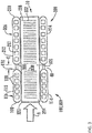
- FIG. 2 is a perspective view of a multiple bank flattened tube finned heat exchanger, generally designated 10, in an exemplary embodiment.
- the multiple bank flattened tube finned heat exchanger 10 includes a first tube bank 100 and a second tube bank 200 that is disposed behind the first tube bank 100, that is downstream with respect to air flow, A, through the heat exchanger 10.
- the first tube bank 100 may also be referred to herein as the front heat exchanger slab 100 and the second tube bank 200 may also be referred to herein as the rear heat exchanger slab 200.
- the first tube bank 100 includes a first manifold 102, a second manifold 104 spaced apart from the first manifold 102, and a plurality of heat exchange tube segments 106, including at least a first and a second tube segment, extending longitudinally in spaced parallel relationship between and connecting the first manifold 102 and the second manifold 104 in fluid communication.
- the second tube bank 200 includes a first manifold 202, a second manifold 204 spaced apart from the first manifold 202, and a plurality of heat exchange tube segments 206, including at least a first and a second tube segment, extending longitudinally in spaced parallel relationship between and connecting the first manifold 202 and the second manifold 204 in fluid communication.
- Each set of manifolds 102, 202 and 104, 204 disposed at either side of the dual bank heat exchanger 10 may comprise separate paired manifolds, may comprise separate chambers within an integral one-piece folded manifold assembly or may comprise separate chambers within an integral fabricated (e.g. extruded, drawn, rolled and welded) manifold assembly.
- Each tube bank 100, 200 may further include guard or "dummy" tubes (not shown) extending between its first and second manifolds at the top of the tube bank and at the bottom of the tube bank. These "dummy" tubes do not convey refrigerant flow, but add structural support to the tube bank and protect the uppermost and lowermost fins.
- each of the heat exchange tube segments 106, 206 comprises a flattened heat exchange tube having a leading edge 108, 208, a trailing edge 110, 210, an upper surface 112, 212, and a lower surface 114, 214.
- the leading edge 108, 208 of each heat exchange tube segment 106, 206 is upstream of its respective trailing edge 110, 210 with respect to airflow through the heat exchanger 10.
- the respective leading and trailing portions of the flattened tube segments 106, 206 are rounded thereby providing blunt leading edges 108, 208 and trailing edges 110, 210.
- the respective leading and trailing portions of the flattened tube segments 106, 206 may be formed in other configurations.
- each of the heat exchange tube segments 106, 206 of the first and second tube banks 100, 200, respectively, may be divided by interior walls into a plurality of discrete flow channels 120, 220 that extend longitudinally the length of the tube from an inlet end of the tube to an outlet end of the tube and establish fluid communication between the respective headers of the first and the second tube banks 100, 200.
- the heat exchange tube segments 206 of the second tube bank 200 have a greater width than the heat exchange tube segments 106 of the first tube bank 100.
- the interior flow passages of the wider heat exchange tube segments 206 may be divided into a greater number of discrete flow channels 220 than the number of discrete flow channels 120 into which the interior flow passages of the heat exchange tube segments 106 are divided.
- the flow channels 120, 220 may have a circular cross-section, a rectangular cross-section or other non-circular cross-section.
- the second tube bank 200 i.e. the rear heat exchanger slab, is disposed behind the first tube bank 100, i.e. the front heat exchanger slab, with respect to the airflow direction, with each heat exchange tube segment 106 directly aligned with a respective heat exchange tube segment 206 and with the leading edges 208 of the heat exchange tube segments 206 of the second tube bank 200 spaced from the trailing edges 110 of the heat exchange tube segments of the first tube bank 100 by a desired spacing, G.
- a spacer or a plurality of spacers disposed at longitudinally spaced intervals may be provided between the trailing edges 110 of the heat exchange tube segments 106 and the leading edges 208 of the heat exchange tube segments 206 to maintain the desired spacing, G, during brazing of the preassembled heat exchanger 10 in a brazing furnace.
- an elongated web 40 or a plurality of spaced web members 40 span the desired spacing gap, G, along at least of portion of the length of each aligned set of heat exchange tube segments 106, 206.
- a dual bank, flattened tube finned heat exchanger wherein the heat exchange tubes 106 of the first tube bank 100 and the heat exchange tubes 206 of the second tube bank 200 are connected by an elongated web or a plurality of web members, reference is made to U.S. provisional application serial number 61/593,979, filed February 2, 2012 , the entire disclosure of which is hereby incorporated herein by reference.
- the flattened tube finned heat exchanger 10 disclosed herein further includes a plurality of folded fins 320.
- Each folded fin 320 is formed of a single continuous strip of fin material tightly folded in a ribbon-like serpentine fashion thereby providing a plurality of closely spaced fins 322 that extend generally orthogonal to the flattened heat exchange tubes 106, 206.
- the fin density of the closely spaced fins 322 of each continuous folded fin 320 may be about 16 to 25 fins per inch, but higher or lower fin densities may also be used.
- each of the ribbon-like folded fin 320 extends at least from the leading edge 108 of the first tube bank 100 to the trailing edge of 210 of the second bank 200, and may overhang the leading edge 108 of the first tube bank 100 or/and trailing edge 208 of the second tube bank 200 as desired.
- each fin 322 of the folded fin 320 may be provided with louvers 330, 332 formed in the first and third sections, respectively, of each fin 322.
- the multiple bank, flattened tube heat exchanger 10 disclosed herein is depicted in a cross-counterflow arrangement wherein refrigerant (labeled "R") from a refrigerant circuit of a refrigerant vapor compression system (such as that of FIG. 1 ) passes through the manifolds and heat exchange tube segments of the tube banks 100, 200, in a manner to be described in further detail hereinafter, in heat exchange relationship with a cooling media, most commonly ambient air, flowing through the airside of the heat exchanger 10 in the direction indicated by the arrow labeled "A" that passes over the outside surfaces of the heat exchange tube segments 106, 206 and the surfaces of the folded fin strips 320.
- R refrigerant
- A most commonly ambient air
- the air flow first passes transversely across the upper and lower horizontal surfaces 112, 114 of the heat exchange tube segments 106 of the first tube bank, and then passes transversely across the upper and lower horizontal surfaces 212, 214 of the heat exchange tube segments 206 of the second tube bank 200.
- the refrigerant passes in cross-counterflow arrangement to the airflow, in that the refrigerant flow passes first through the second tube bank 200 and then through the first tube bank 100.
- the multiple tube bank, flattened tube finned heat exchanger 10 having a cross-counterflow circuit arrangement yields superior heat exchange performance, as compared to the crossflow or cross-parallel flow circuit arrangements, as well as allows for flexibility to manage the refrigerant side pressure drop via implementation of tubes of various widths within the first tube bank 100 and the second tube bank 200.
- the second tube bank 200 i.e. the rear heat exchanger slab with respect to air flow
- the first tube bank 100 i.e. the front heat exchanger slab with respect to air flow
- Refrigerant flow passes from a refrigerant circuit into the first manifold 202 of the second tube bank 200 through at least one refrigerant inlet, passes through the heat exchange tube segments 206 into the second manifold 204 of the second tube bank 200, then passes into the second manifold 104 of the first tube bank 100, thence through a lower set of the heat exchange segments 106 into the first manifold 102 of the first tube bank 100, thence back to the second manifold 104 through an upper set of the heat exchange tubes 106, and thence passes back to the refrigerant circuit through at least one refrigerant outlet 122.
- a separator 105 divides the second manifold 104 of the first tube bank 100 into two chambers.
- the neighboring second manifolds 104 and 204 are connected in fluid flow communication such that refrigerant may flow from the interior of the second manifold 204 of the second tube bank 200 into the interior of the second manifold 104 of the first tube bank 100.
- the first tube bank 100 and second tube bank 200 may be brazed together to form an integral unit with a single fin 326 spanning both tube banks that facilitates handling and installation of heat exchanger 10.
- the first tube bank 100 and second tube bank 200 may be assembled as separate slabs and then brazed together as a composite heat exchanger.
- the embodiment of FIG. 3 depicts heat exchange tube segments 106 aligned with heat exchange tube segments 206. It is understood that in other embodiments, heat exchange tube segments 106 may be offset or staggered with respect to heat exchange tube segments 206.
- the multiple bank flattened tube finned heat exchanger 10 provides improved refrigerant circuiting when used, for example, in a chiller.
- FIG. 4 depicts two multiple bank flattened tube finned heat exchangers 10 and 10' arranged in a V configuration, typical of rooftop condenser.
- a fan 11 draws air through heat exchangers 10 and 10'.
- Typical air-cooled chillers employ single slab heat exchangers.
- the conventional single slab heat exchangers employ pure crossflow circuiting with air flowing in a vertical plane and generally perpendicular to the refrigerant flow.
- the multiple bank flattened tube finned heat exchanger 10 employs cross-counterflow refrigerant circuiting wherein the air is flowing in the direction generally opposite to the refrigerant.
- the cross-counterflow circuiting is thermodynamically more efficient for the heat transfer due to overall higher driving potential that could be achieved.
- the conventional heat exchangers widely in use today are symmetric in terms of air inlet or outlet faces, which is a result of the pure crossflow refrigerant circuiting.
- the multiple bank flattened tube finned heat exchangers 10 and 10' when installed in a V module, have a left and a right hand design distinction, which is a consequence of the cross-counterflow arrangement. Therefore the two multiple bank flattened tube finned heat exchanger 10 and 10' as installed in a V module are mirror images of each other as shown in FIG. 4 .
- the conventional single slab heat exchangers are typically limited to two crossflow passes of refrigerant across the flow length between the two heat exchanger headers, typically due to the pressure drop limitation-.
- the multiple bank flattened tube finned heat exchanger 10 provides three refrigerant passes shown in FIG. 2 as a first pass 401, second pass 402 and third pass 403.
- First pass 401 occupies the second tube bank 200, which corresponds to about 50% of the total heat exchange area of heat exchanger 10.
- the first refrigerant pass 401 is dedicated for desuperheating and initial condensing. In air-cooled chiller applications, the refrigerant quality in the manifold 204 should remain relatively high, about 0.6-0.8.
- the second pass 402 occupy no more than about 40% and no less than about 30% of the total heat exchange area of heat exchanger 10.
- the refrigerant quality should be very low and no more than about 0.2-0.4, once again allowing for uniform refrigerant distribution, since the refrigerant composition contains predominantly single phase liquid that flows into the third pass 403.
- the third pass 403 should be about 10% to about 20% of the total heat exchange area of heat exchanger 10.
- Third pass 403 provides a subcooling circuit. The location of the subcooling circuit is preferably positioned in the highest airflow region, typically closer to fan 11.
- the subcooling circuit may be positioned at the bottom of the heat exchanger 10.
- FIG. 5 depicts an embodiment to reduce or eliminate the possibility of thermal mechanical fatigue. Shown in FIG. 5 is a portion of heat exchanger tube segment 106, a portion of heat exchanger tube segment 206, and webs 40 joining heat exchanger tube segments 106 and 206. Folded fins 320 are not shown for ease of illustration. Web 40a closest to a distal end of heat exchanger tube segments 106 and 206 is scored at score line 41 to weaken web 40a. A web at the opposite distal end of tube segments 106 and 206 may also be scored. Scoring web 40 provides a path of least resistance for crack propagation due to different thermal expansion of various components of heat exchanger 10.
- the score line 41 may extend the entire width of the web 40a or just a portion of the web 40a.
- Embodiments include dimensional relationships among components of the heat exchanger 10.
- the gap, G, ( FIG. 3 ) is about 15% to about 25% of the overall tube segment depth, that is, the distance from leading edge 108 of tube segment 106 to the trailing edge 210 of tube segment 206.
- This spacing may be used if the heat exchanger 10 uses individual tubes or integral tube segments joined by web 40.
- the web 40 may be slotted along its length.
- slots in web 40 are about 90% to about 95% of the total tube segment length to provide enhanced water drainage and minimal cross-conduction while maintaining manufacturing integrity. In other words, webs 40 take up about 5% to about 10% of the space in gap G along the total tube segment length.
- an individual tube segment 106, 206 width is about 30% to about 50% heat exchanger core depth.
- manifold outer diameter (OD) range is about 1.4 to about 2.2 times the tube segment width (e.g., from leading edge to trailing edge) in air-cooled chiller applications.
- the fin density of folded fin 320 air-cooled chiller application is from about 19 to about 22 fins per inch.
- the range of fin height to tube segment pitch ratio is about 0.45 to about 1.4.
- Tube segment pitch is spacing between flattened tube segments in the first tube bank, or spacing between flattened tube segments the second tube bank.
- the tube segment width is about 10 mm to about 16 mm
- the tube segment height is about 1.6 mm to about 2.2 mm
- the tube segment port size is about 0.8 mm to about 1.2 mm
- the fin height is about 7.8 mm to about 8.2 mm
- the fin thickness is about 0.07 mm to about 0.09 mm
- the number of louvers is about 9 to about 11 per bank (while typically having 2 banks per tube)
- the louver height is from about 80% to about 95% of the fin height
- the manifold diameter is about 18mm to 22 mm
- the gap between the inlet headers is about 2 mm to about 3mm
- the manifold slots offset is about 2 mm to about 3mm
- the number of slabs is about 2 to about 4.
- Embodiments include improved routing of refrigerant to and from heat exchanger 10.
- the current practice of using conventional heat exchangers in air-cooled chillers is to have the inlet and outlet piping at the same side on the same manifold.
- the hot incoming refrigerant is separated by the cold outgoing refrigerant by a separator plate across which there is a large thermal gradient. This is detrimental from a thermal-mechanical-fatigue perspective and a thermal performance (cross-conduction) point of view.
- the inlet and outlet connection pipes are positioned on different manifolds resolving the two issues outlined hereabove. For example, as shown in FIG. 1 , inlet manifold 202 is at an opposite end of heat exchanger 10 from outlet manifold 104.
- heat exchanger 10 includes three inlet pipes compared to two for the conventional heat exchangers. This results in more uniform refrigerant distribution, lower pressure drop penalty and lower susceptibility to thermal-mechanical-fatigue (due to more uniform manifold expansion).
- refrigerant inlet pipes are appropriately spaced and positioned on the back slab towards the interior of the 'V' module.
- Exemplary inlet pipes 12 for heat exchanger 10 are depicted in FIG. 4 .
- the heat exchanger outlet pipe is typically positioned on the front slab toward the exterior of the 'V' module.
- Exemplary outlet pipe 13 for heat exchanger 10 is depicted in FIG. 4 .
- a frame 15 may be used to protect heat exchanger 10 from handling damage and galvanic corrosion as well as for ease of installation.
- Frame 15 may be a C-shaped channel that surrounds the outer edges of heat exchanger 10.
- the frame may include rubber grommets and installation pads positioned between the frame 15 and the heat exchanger 10 to accommodate the heat exchanger 10 core and dual manifold configuration.
- heat exchanger 10 may be employed in a modular condenser configuration.
- FIGS. 6 and 7 an air-cooled condenser 514, such as used in the vapor compression cycle 500 of FIG. 1 , is illustrated in more detail.
- the condenser 514 includes one or more identical condenser modules 22 positioned within a support 20, such as the type of support 20 normally found on building rooftops for example. Any number of condenser modules 22 may be installed within the support 20 to form a condenser 514 configured to meet the capacity and cooling requirements for a given application.
- FIG. 6 an air-cooled condenser 514, such as used in the vapor compression cycle 500 of FIG. 1 , is illustrated in more detail.
- the condenser 514 includes one or more identical condenser modules 22 positioned within a support 20, such as the type of support 20 normally found on building rooftops for example. Any number of condenser modules 22 may be installed within the support 20 to form a condenser 514 configured to meet the capacity and
- the condenser module 22 includes a housing or cabinet 24 configured to be received within the support 20. Opposing lateral sides 26, 28 of the housing 24 each define an inlet for air to flow into the module 22. Similarly, a first end 30 of the housing 24, connected to both of the opposing lateral sides 26, 28, defines an outlet opening for air to exit from the condenser module 22.
- the condenser modules 22 are positioned within the support 20 such that at least one of an opposing front surface and back surface of the housing 24 is arranged adjacent to either a front surface or a back surface of the housing 24 of another condenser module 22 (see FIG. 6 ).
- a heat exchanger assembly 32 Located within the housing 24 of the condenser module 22 is a heat exchanger assembly 32 arranged generally longitudinally between the lateral sides 26, 28.
- the cross-section of the heat exchanger assembly 32 is generally constant over a length of the condenser module 22, such as between the front surface and the back surface.
- the heat exchanger assembly 32 includes at least one heat exchanger 10, such as that shown in FIG. 2 .
- a plurality of heat exchangers 10, 10' of the heat exchanger assembly 32 may be arranged generally symmetrically about a center of the condenser module 22 between the opposing lateral sides 26, 28, as illustrated schematically by line C.
- the heat exchanger assembly 32 includes a first heat exchanger 10 mounted to the first lateral side 26 of the housing 24 and a second, substantially identical heat exchanger 10' mounted to the second lateral side 28 of the housing 24.
- the plurality of heat exchangers 10, 10' may be arranged within the housing 24 such that the heat exchanger assembly 32 has a generally V-shaped configuration, as shown in FIG. 4 .
- Alternative configurations of the heat exchanger assembly 32, such as the generally U-shaped configuration illustrated in FIG. 6 for example, are also within the scope of the invention.
- heat exchangers 10, 10' are arranged in V-shaped configuration, but rotated relative to the orientation shown in FIG. 7 .
- an axis corresponding to an apex of the V shape may be parallel to a longitudinal axis of the housing 24.
- heat exchangers 10, 10' may be positioned so that the axis corresponding to an apex of the V shape is perpendicular to the longitudinal axis of the housing 24.
- the airflow for the multi-slab microchannel heat exchangers in air-cooled chiller applications is required to be between about 300 feet per minute and about 700 feet per minute, for optimal performance. More precisely, the airflow should be in the range between about 400 feet per minute and about 500 feet per minute.
- the refrigerant flow rate per multi-slab microchannel heat exchanger in a typical V module for air-cooled applications should be between about 2500 pounds per hour to about 4500 pounds per hour.
- the inventive heat exchanger design is optimal for and can be used with the high pressure refrigerants such as R410A and low pressure refrigerants such as R134a.
- the condenser module 22 additionally includes a fan assembly 40 configured to circulate air through the housing 24 and the heat exchanger assembly 32.
- the fan assembly 40 may be positioned either downstream with respect to the heat exchanger assembly 32 (i.e. "draw through configuration") as shown in the FIG. 7 , or upstream with respect to the heat exchanger assembly 32 (i.e. "blow through configuration").
- the fan assembly 40 is mounted at the first end 30 of the housing 24 in a draw-through configuration.
- the fan assembly 40 generally includes a plurality of fans 42 such that the number of fans 42 configured to draw air through each of the respective heat exchangers 10 is identical.
- the plurality of fans 42 in the fan assembly 40 substantially equals the plurality of heat exchangers 10 in the heat exchanger assembly 32.
- the at least one fan 42 configured to draw air through a single heat exchanger 10 is generally vertically aligned with that respective heat exchanger 10 such that the plurality of fans 42 in the fan assembly 40 are substantially symmetrical about center line C.
- the heat exchanger assembly 32 includes a first heat exchanger 10 and second heat exchanger coil 10'
- at least a first fan 42' is generally aligned with the first heat exchanger 10 and at least a second fan 42" is generally aligned with the second heat exchanger 10'.
- a divider (not shown), such as formed from a piece of sheet metal for example, extends inwardly from the first end of the housing 24 along the center line C.
- the divider may be used to separate the condenser module 22 including the heat exchanger 10 and the fan assembly 40 into a plurality of generally identical modular portions, such as a first portion 46 and a second portion 48 for example.
- Such configuration may also allow for a more efficient part-load operation.
- Operation of the at least one fan 42 associated with the at least one heat exchanger 10 in either the first or second modular portion 46, 48 of the condenser module 22 causes air to flow through an adjacent air inlet and into the housing 24.
- the air passes over the heat exchanger 10
- the at least one fan 42 of that modular portion 46, 48 may be turned off to limit the power consumption and improve the efficiency of the condenser module 22.
- the heat exchanger assembly 32 By arranging the heat exchanger assembly 32 generally longitudinally between the opposing lateral sides 26, 28 of the housing 24, the number of turns in the flow path of air entering the housing 24 is reduced to a single turn. This new orientation of the heat exchanger assembly 32 also allows for better run off which reduces the likelihood of corrosion and allows for evaporative condensing.
- inclusion of generally modular portions 46, 48 within each condenser module 22 provides up to a significant reduction in the system losses in the module 22 as well as in the required fan power. Because the velocity of the air through the housing 24 is more uniform and the overall airflow is increased (due to lower flow losses), the heat transfer capability of the condenser module 22 is improved.
Description
- This invention relates generally to heat exchangers and, more particularly, to a multiple tube bank heat exchanger for use in an air-cooled chiller system as defined in the preamble of
claim 1. Such apparatuses are known , for instance, fromWO2012/071196A2 . - In a conventional air conditioning system, the condenser of the refrigeration circuit is located exterior to a building. Typically, the condenser includes a condensing heat exchanger and a fan for circulating a cooling medium (e.g., air) over the condensing heat exchanger. The air conditioning system further includes an indoor unit having an evaporator for transferring heat energy from the indoor air to be conditioned to the refrigerant flowing through the evaporator and a fan for circulating the indoor air in a heat exchange relationship with the evaporator.
- Air-cooled condensers, including air-cooled chillers and rooftops, are often used for applications requiring large capacity cooling and heating. Because larger condenser heat exchanger surfaces are needed for the functionality of the system, the condenser generally includes a plurality of condensers units. Multiple fans are located on top of the condenser housing for each unit.
- Historically, these heat exchangers in condensers have been round tube and plate fin (RTPF) heat exchangers. However, all aluminum flattened tube serpentine fin heat exchangers are finding increasingly wider use in industry, including the heating, ventilation, air condition and refrigeration (HVACR) industry, due to their compactness, thermal-hydraulic performance, structural rigidity, lower weight and reduced refrigerant charge, in comparison to conventional RTPF heat exchangers. Flattened tubes commonly used in HVACR applications typically have an interior subdivided into a plurality of parallel flow channels. Such flattened tubes are commonly referred to in the art as multi-channel tubes, mini-channel tubes or micro-channel tubes.
- A typical flattened tube serpentine fin heat exchanger includes a first manifold, a second manifold, and a single tube bank formed of a plurality of longitudinally extending flattened heat exchange tubes disposed in spaced parallel relationship and extending between the first manifold and the second manifold. The first manifold, second manifold and tube bank assembly is commonly referred to in the heat exchanger art as a slab. Additionally, a plurality of fins are disposed between the neighboring pairs of heat exchange tubes for increasing heat transfer between a fluid, commonly air in HVACR applications, flowing over the outside surfaces of the flattened tubes and along the fin surfaces and a fluid, commonly refrigerant in HVACR applications, flowing inside the flattened tubes, Such single tube bank heat exchangers, also known as single slab heat exchangers, have a pure cross-flow configuration.
- Double bank flattened tube and serpentine fin heat exchangers are also known in the art. Conventional double bank flattened tube and serpentine fin heat exchangers are typically formed of two conventional fin and tube slabs, one positioned behind the other, with fluid communication between the manifolds accomplished through external piping. However, to connect the two slabs in fluid flow communication in other than a parallel cross-flow arrangement requires complex external piping and precise heat exchanger slab alignment. For example,
U.S. Patent 6,964,296 B2 andU.S. Patent Application Publication 2009/0025914 A1 disclose embodiments of double bank, multichannel flattened tube heat exchanger. - According to the invention, there is provided an air-cooled chiller system according to
claim 1. - For further understanding of the disclosure, reference will be made to the following detailed description which is to be read in connection with the accompanying drawings, where:
-
FIG. 1 depicts a vapor-compression cycle of an air conditioning system in an exemplary embodiment; -
FIG. 2 depicts a multiple tube bank, flattened tube finned heat exchanger in an exemplary embodiment; -
FIG. 3 is a side elevation view, partly in section, illustrating a fin and a set of integral flattened tube segment assemblies of the heat exchanger ofFIG. 2 ; -
FIG. 4 depicts heat exchangers ofFIG. 2 mounted in a V-orientation; -
FIG. 5 depicts flattened tube segments and a web in an exemplary embodiment; -
FIG. 6 is a perspective view of a condenser in an exemplary embodiment; and -
FIG. 7 is a front view, partly in section, of a condenser module in an exemplary embodiment. - Referring now to
FIG. 1 , a vapor compression orrefrigeration cycle 500 of an air conditioning system is schematically illustrated. Exemplary air conditioning systems include split, packaged, chiller and rooftop systems, for example. A refrigerant R is configured to circulate through thevapor compression cycle 500 such that the refrigerant R absorbs heat when evaporated at a low temperature and pressure and releases heat when condensing at a higher temperature and pressure. Within thiscycle 500, the refrigerant R flows in a counterclockwise direction as indicated by the arrows. Thecompressor 512 receives refrigerant vapor from theevaporator 518 and compresses it to a higher temperature and pressure, with the relatively hot vapor then passing to thecondenser 514 where it is cooled and condensed to a liquid state by a heat exchange relationship with a cooling medium such as air or water. The liquid refrigerant R then passes from thecondenser 514 to anexpansion device 516, wherein the refrigerant R is expanded to a low temperature two-phase liquid/vapor state as it passes to theevaporator 518. The low pressure vapor then returns to thecompressor 512 where the cycle is repeated. It has to be understood that therefrigeration cycle 500 depicted inFIG. 1 is a simplistic representation of the HVAC&R system, and many enhancements and features known in the art may be included in the schematic. Furthermore, therefrigeration cycle 500 may operate in the super-critical region, where the high pressure refrigerant state is above the critical point and is represented by a single-phase medium. -
FIG. 2 is a perspective view of a multiple bank flattened tube finned heat exchanger, generally designated 10, in an exemplary embodiment. As depicted therein, the multiple bank flattened tube finnedheat exchanger 10 includes afirst tube bank 100 and asecond tube bank 200 that is disposed behind thefirst tube bank 100, that is downstream with respect to air flow, A, through theheat exchanger 10. Thefirst tube bank 100 may also be referred to herein as the frontheat exchanger slab 100 and thesecond tube bank 200 may also be referred to herein as the rearheat exchanger slab 200. - The
first tube bank 100 includes afirst manifold 102, asecond manifold 104 spaced apart from thefirst manifold 102, and a plurality of heatexchange tube segments 106, including at least a first and a second tube segment, extending longitudinally in spaced parallel relationship between and connecting thefirst manifold 102 and thesecond manifold 104 in fluid communication. Thesecond tube bank 200 includes afirst manifold 202, asecond manifold 204 spaced apart from thefirst manifold 202, and a plurality of heatexchange tube segments 206, including at least a first and a second tube segment, extending longitudinally in spaced parallel relationship between and connecting thefirst manifold 202 and thesecond manifold 204 in fluid communication. Each set ofmanifolds bank heat exchanger 10 may comprise separate paired manifolds, may comprise separate chambers within an integral one-piece folded manifold assembly or may comprise separate chambers within an integral fabricated (e.g. extruded, drawn, rolled and welded) manifold assembly. Eachtube bank - Referring now to
FIG. 3 , each of the heatexchange tube segments edge trailing edge upper surface 112, 212, and alower surface edge exchange tube segment trailing edge heat exchanger 10. In the embodiment depicted inFIG. 3 , the respective leading and trailing portions of theflattened tube segments edges trailing edges flattened tube segments - The interior flow passage of each of the heat
exchange tube segments second tube banks discrete flow channels second tube banks exchange tube segments FIG. 3 , the heatexchange tube segments 206 of thesecond tube bank 200 have a greater width than the heatexchange tube segments 106 of thefirst tube bank 100. Also, the interior flow passages of the wider heatexchange tube segments 206 may be divided into a greater number ofdiscrete flow channels 220 than the number ofdiscrete flow channels 120 into which the interior flow passages of the heatexchange tube segments 106 are divided. Theflow channels - The
second tube bank 200, i.e. the rear heat exchanger slab, is disposed behind thefirst tube bank 100, i.e. the front heat exchanger slab, with respect to the airflow direction, with each heatexchange tube segment 106 directly aligned with a respective heatexchange tube segment 206 and with theleading edges 208 of the heatexchange tube segments 206 of thesecond tube bank 200 spaced from thetrailing edges 110 of the heat exchange tube segments of thefirst tube bank 100 by a desired spacing, G. A spacer or a plurality of spacers disposed at longitudinally spaced intervals may be provided between thetrailing edges 110 of the heatexchange tube segments 106 and the leadingedges 208 of the heatexchange tube segments 206 to maintain the desired spacing, G, during brazing of the preassembledheat exchanger 10 in a brazing furnace. - In the embodiment depicted in
FIG. 3 , anelongated web 40 or a plurality of spacedweb members 40 span the desired spacing gap, G, along at least of portion of the length of each aligned set of heatexchange tube segments heat exchange tubes 106 of thefirst tube bank 100 and theheat exchange tubes 206 of thesecond tube bank 200 are connected by an elongated web or a plurality of web members, reference is made toU.S. provisional application serial number 61/593,979, filed February 2, 2012 - Referring still to
FIGs. 2 and3 , the flattened tube finnedheat exchanger 10 disclosed herein further includes a plurality of folded fins 320. Each foldedfin 320 is formed of a single continuous strip of fin material tightly folded in a ribbon-like serpentine fashion thereby providing a plurality of closely spacedfins 322 that extend generally orthogonal to the flattenedheat exchange tubes fins 322 of each continuous foldedfin 320 may be about 16 to 25 fins per inch, but higher or lower fin densities may also be used. Heat exchange between the refrigerant flow, R, and air flow, A, occurs through theoutside surfaces exchange tube segments fins 322 of the foldedfin 320, which forms the secondary heat exchange surface. - In the depicted embodiment, the depth of each of the ribbon-like folded
fin 320 extends at least from the leadingedge 108 of thefirst tube bank 100 to the trailing edge of 210 of thesecond bank 200, and may overhang the leadingedge 108 of thefirst tube bank 100 or/andtrailing edge 208 of thesecond tube bank 200 as desired. Thus, when a foldedfin 320 is installed between a set of adjacent multiple tube, flattened heat exchange tube assemblies 240 in the array of tube assemblies of the assembledheat exchanger 10, afirst section 324 of eachfin 322 is disposed within thefirst tube bank 100, asecond section 326 of eachfin 322 spans the spacing, G, between thetrailing edge 110 of thefirst tube bank 100 and the leadingedge 208 of thesecond tube bank 200, and athird section 328 of eachfin 322 is disposed within thesecond tube bank 200. In an embodiment, eachfin 322 of the foldedfin 320 may be provided withlouvers 330, 332 formed in the first and third sections, respectively, of eachfin 322. - The multiple bank, flattened
tube heat exchanger 10 disclosed herein is depicted in a cross-counterflow arrangement wherein refrigerant (labeled "R") from a refrigerant circuit of a refrigerant vapor compression system (such as that ofFIG. 1 ) passes through the manifolds and heat exchange tube segments of thetube banks heat exchanger 10 in the direction indicated by the arrow labeled "A" that passes over the outside surfaces of the heatexchange tube segments fin strips 320. The air flow first passes transversely across the upper and lowerhorizontal surfaces 112, 114 of the heatexchange tube segments 106 of the first tube bank, and then passes transversely across the upper and lowerhorizontal surfaces exchange tube segments 206 of thesecond tube bank 200. The refrigerant passes in cross-counterflow arrangement to the airflow, in that the refrigerant flow passes first through thesecond tube bank 200 and then through thefirst tube bank 100. The multiple tube bank, flattened tubefinned heat exchanger 10 having a cross-counterflow circuit arrangement yields superior heat exchange performance, as compared to the crossflow or cross-parallel flow circuit arrangements, as well as allows for flexibility to manage the refrigerant side pressure drop via implementation of tubes of various widths within thefirst tube bank 100 and thesecond tube bank 200. - In the embodiment depicted in
FIGs. 2 and3 , thesecond tube bank 200, i.e. the rear heat exchanger slab with respect to air flow, has a first, single-pass refrigerant circuit 401 configuration and thefirst tube bank 100, i.e. the front heat exchanger slab with respect to air flow, has a two pass configuration withpasses first manifold 202 of thesecond tube bank 200 through at least one refrigerant inlet, passes through the heatexchange tube segments 206 into thesecond manifold 204 of thesecond tube bank 200, then passes into thesecond manifold 104 of thefirst tube bank 100, thence through a lower set of theheat exchange segments 106 into thefirst manifold 102 of thefirst tube bank 100, thence back to thesecond manifold 104 through an upper set of theheat exchange tubes 106, and thence passes back to the refrigerant circuit through at least one refrigerant outlet 122. Aseparator 105 divides thesecond manifold 104 of thefirst tube bank 100 into two chambers. - In the embodiments depicted in
FIGs. 2 and3 , the neighboringsecond manifolds second manifold 204 of thesecond tube bank 200 into the interior of thesecond manifold 104 of thefirst tube bank 100. In the embodiment depicted inFIG. 3 , thefirst tube bank 100 andsecond tube bank 200 may be brazed together to form an integral unit with asingle fin 326 spanning both tube banks that facilitates handling and installation ofheat exchanger 10. However thefirst tube bank 100 andsecond tube bank 200 may be assembled as separate slabs and then brazed together as a composite heat exchanger. The embodiment ofFIG. 3 depicts heatexchange tube segments 106 aligned with heatexchange tube segments 206. It is understood that in other embodiments, heatexchange tube segments 106 may be offset or staggered with respect to heatexchange tube segments 206. - The multiple bank flattened tube
finned heat exchanger 10 provides improved refrigerant circuiting when used, for example, in a chiller.FIG. 4 depicts two multiple bank flattened tubefinned heat exchangers 10 and 10' arranged in a V configuration, typical of rooftop condenser. Afan 11 draws air throughheat exchangers 10 and 10'. Typical air-cooled chillers employ single slab heat exchangers. The conventional single slab heat exchangers employ pure crossflow circuiting with air flowing in a vertical plane and generally perpendicular to the refrigerant flow. The multiple bank flattened tubefinned heat exchanger 10 employs cross-counterflow refrigerant circuiting wherein the air is flowing in the direction generally opposite to the refrigerant. The cross-counterflow circuiting is thermodynamically more efficient for the heat transfer due to overall higher driving potential that could be achieved. The conventional heat exchangers widely in use today are symmetric in terms of air inlet or outlet faces, which is a result of the pure crossflow refrigerant circuiting. The multiple bank flattened tubefinned heat exchangers 10 and 10', when installed in a V module, have a left and a right hand design distinction, which is a consequence of the cross-counterflow arrangement. Therefore the two multiple bank flattened tubefinned heat exchanger 10 and 10' as installed in a V module are mirror images of each other as shown inFIG. 4 . - The conventional single slab heat exchangers are typically limited to two crossflow passes of refrigerant across the flow length between the two heat exchanger headers, typically due to the pressure drop limitation-. The multiple bank flattened tube
finned heat exchanger 10 provides three refrigerant passes shown inFIG. 2 as afirst pass 401,second pass 402 andthird pass 403. First pass 401 occupies thesecond tube bank 200, which corresponds to about 50% of the total heat exchange area ofheat exchanger 10. The firstrefrigerant pass 401 is dedicated for desuperheating and initial condensing. In air-cooled chiller applications, the refrigerant quality in the manifold 204 should remain relatively high, about 0.6-0.8. This allows for uniform refrigerant distribution, since the refrigerant composition contains predominantly single phase vapor that flows into thesecond pass 402. Thesecond pass 402 occupy no more than about 40% and no less than about 30% of the total heat exchange area ofheat exchanger 10. After thesecond pass 402, the refrigerant quality should be very low and no more than about 0.2-0.4, once again allowing for uniform refrigerant distribution, since the refrigerant composition contains predominantly single phase liquid that flows into thethird pass 403. Thethird pass 403 should be about 10% to about 20% of the total heat exchange area ofheat exchanger 10.Third pass 403 provides a subcooling circuit. The location of the subcooling circuit is preferably positioned in the highest airflow region, typically closer to fan 11. Conversely, if other limitations are imposed on the heat exchanger, such as self-draining refrigerant requirement for the so-called "free-cooling" feature in the air-cooled chiller applications, the subcooling circuit may be positioned at the bottom of theheat exchanger 10. - Thermal mechanical fatigue is a known phenomenon in air-cooled chiller applications.
FIG. 5 depicts an embodiment to reduce or eliminate the possibility of thermal mechanical fatigue. Shown inFIG. 5 is a portion of heatexchanger tube segment 106, a portion of heatexchanger tube segment 206, andwebs 40 joining heatexchanger tube segments fins 320 are not shown for ease of illustration.Web 40a closest to a distal end of heatexchanger tube segments score line 41 to weakenweb 40a. A web at the opposite distal end oftube segments web 40 provides a path of least resistance for crack propagation due to different thermal expansion of various components ofheat exchanger 10. Therefore, a crack will not be initiated at the locations that are critical for the heat exchanger functionality such as tube-to-manifold joint, which is a typical thermal mechanical fatigue crack initiation site. Thescore line 41 may extend the entire width of theweb 40a or just a portion of theweb 40a. - Embodiments include dimensional relationships among components of the
heat exchanger 10. In an exemplary embodiment, the gap, G, (FIG. 3 ) is about 15% to about 25% of the overall tube segment depth, that is, the distance from leadingedge 108 oftube segment 106 to the trailingedge 210 oftube segment 206. This spacing may be used if theheat exchanger 10 uses individual tubes or integral tube segments joined byweb 40. While using integrally formedtubes web 40 may be slotted along its length. In an exemplary embodiment, slots inweb 40 are about 90% to about 95% of the total tube segment length to provide enhanced water drainage and minimal cross-conduction while maintaining manufacturing integrity. In other words,webs 40 take up about 5% to about 10% of the space in gap G along the total tube segment length. In an exemplary embodiment, anindividual tube segment fin 320 air-cooled chiller application is from about 19 to about 22 fins per inch. In an exemplary embodiment, the range of fin height to tube segment pitch ratio is about 0.45 to about 1.4. Tube segment pitch is spacing between flattened tube segments in the first tube bank, or spacing between flattened tube segments the second tube bank. In an exemplary air-cooled chiller applications, the tube segment width is about 10 mm to about 16 mm, the tube segment height is about 1.6 mm to about 2.2 mm, the tube segment port size is about 0.8 mm to about 1.2 mm, the fin height is about 7.8 mm to about 8.2 mm, the fin thickness is about 0.07 mm to about 0.09 mm, the number of louvers is about 9 to about 11 per bank (while typically having 2 banks per tube), the louver height is from about 80% to about 95% of the fin height, the manifold diameter is about 18mm to 22 mm, the gap between the inlet headers is about 2 mm to about 3mm, the manifold slots offset is about 2 mm to about 3mm, and the number of slabs is about 2 to about 4. - Embodiments include improved routing of refrigerant to and from
heat exchanger 10. The current practice of using conventional heat exchangers in air-cooled chillers is to have the inlet and outlet piping at the same side on the same manifold. The hot incoming refrigerant is separated by the cold outgoing refrigerant by a separator plate across which there is a large thermal gradient. This is detrimental from a thermal-mechanical-fatigue perspective and a thermal performance (cross-conduction) point of view. In embodiments of the invention, the inlet and outlet connection pipes are positioned on different manifolds resolving the two issues outlined hereabove. For example, as shown inFIG. 1 ,inlet manifold 202 is at an opposite end ofheat exchanger 10 fromoutlet manifold 104. In exemplary embodiments,heat exchanger 10 includes three inlet pipes compared to two for the conventional heat exchangers. This results in more uniform refrigerant distribution, lower pressure drop penalty and lower susceptibility to thermal-mechanical-fatigue (due to more uniform manifold expansion). In exemplary embodiments, refrigerant inlet pipes are appropriately spaced and positioned on the back slab towards the interior of the 'V' module.Exemplary inlet pipes 12 forheat exchanger 10 are depicted inFIG. 4 . The heat exchanger outlet pipe is typically positioned on the front slab toward the exterior of the 'V' module.Exemplary outlet pipe 13 forheat exchanger 10 is depicted inFIG. 4 . This arrangement allows for better optimization of refrigerant piping length with respect to adjacent components such as compressors and coolers. Aframe 15 may be used to protectheat exchanger 10 from handling damage and galvanic corrosion as well as for ease of installation.Frame 15 may be a C-shaped channel that surrounds the outer edges ofheat exchanger 10. The frame may include rubber grommets and installation pads positioned between theframe 15 and theheat exchanger 10 to accommodate theheat exchanger 10 core and dual manifold configuration. - In addition to the V module of
FIG. 4 ,heat exchanger 10 may be employed in a modular condenser configuration. Referring now toFIGS. 6 and7 , an air-cooledcondenser 514, such as used in thevapor compression cycle 500 ofFIG. 1 , is illustrated in more detail. As shown inFIG.6 , thecondenser 514 includes one or moreidentical condenser modules 22 positioned within asupport 20, such as the type ofsupport 20 normally found on building rooftops for example. Any number ofcondenser modules 22 may be installed within thesupport 20 to form acondenser 514 configured to meet the capacity and cooling requirements for a given application. Referring now to theexemplary condenser module 22 illustrated inFIG. 7 , thecondenser module 22 includes a housing orcabinet 24 configured to be received within thesupport 20. Opposinglateral sides housing 24 each define an inlet for air to flow into themodule 22. Similarly, afirst end 30 of thehousing 24, connected to both of the opposinglateral sides condenser module 22. In one embodiment, thecondenser modules 22 are positioned within thesupport 20 such that at least one of an opposing front surface and back surface of thehousing 24 is arranged adjacent to either a front surface or a back surface of thehousing 24 of another condenser module 22 (seeFIG. 6 ). - Located within the
housing 24 of thecondenser module 22 is aheat exchanger assembly 32 arranged generally longitudinally between thelateral sides heat exchanger assembly 32 is generally constant over a length of thecondenser module 22, such as between the front surface and the back surface. Theheat exchanger assembly 32 includes at least oneheat exchanger 10, such as that shown inFIG. 2 . A plurality ofheat exchangers 10, 10' of theheat exchanger assembly 32 may be arranged generally symmetrically about a center of thecondenser module 22 between the opposinglateral sides heat exchanger assembly 32 includes afirst heat exchanger 10 mounted to the firstlateral side 26 of thehousing 24 and a second, substantially identical heat exchanger 10' mounted to the secondlateral side 28 of thehousing 24. The plurality ofheat exchangers 10, 10' may be arranged within thehousing 24 such that theheat exchanger assembly 32 has a generally V-shaped configuration, as shown inFIG. 4 . Alternative configurations of theheat exchanger assembly 32, such as the generally U-shaped configuration illustrated inFIG. 6 for example, are also within the scope of the invention. In other embodiments,heat exchangers 10, 10' are arranged in V-shaped configuration, but rotated relative to the orientation shown inFIG. 7 . That is, an axis corresponding to an apex of the V shape may be parallel to a longitudinal axis of thehousing 24. Alternatively,heat exchangers 10, 10' may be positioned so that the axis corresponding to an apex of the V shape is perpendicular to the longitudinal axis of thehousing 24. - The airflow for the multi-slab microchannel heat exchangers in air-cooled chiller applications is required to be between about 300 feet per minute and about 700 feet per minute, for optimal performance. More precisely, the airflow should be in the range between about 400 feet per minute and about 500 feet per minute. The refrigerant flow rate per multi-slab microchannel heat exchanger in a typical V module for air-cooled applications should be between about 2500 pounds per hour to about 4500 pounds per hour. Furthermore, the inventive heat exchanger design is optimal for and can be used with the high pressure refrigerants such as R410A and low pressure refrigerants such as R134a.
- The
condenser module 22 additionally includes afan assembly 40 configured to circulate air through thehousing 24 and theheat exchanger assembly 32.. Depending on the characteristics of thecondenser module 22, thefan assembly 40 may be positioned either downstream with respect to the heat exchanger assembly 32 (i.e. "draw through configuration") as shown in theFIG. 7 , or upstream with respect to the heat exchanger assembly 32 (i.e. "blow through configuration"). - In one embodiment, the
fan assembly 40 is mounted at thefirst end 30 of thehousing 24 in a draw-through configuration. Thefan assembly 40 generally includes a plurality offans 42 such that the number offans 42 configured to draw air through each of therespective heat exchangers 10 is identical. In one embodiment, the plurality offans 42 in thefan assembly 40 substantially equals the plurality ofheat exchangers 10 in theheat exchanger assembly 32. In addition, the at least onefan 42 configured to draw air through asingle heat exchanger 10 is generally vertically aligned with thatrespective heat exchanger 10 such that the plurality offans 42 in thefan assembly 40 are substantially symmetrical about center line C. For example, in embodiments where theheat exchanger assembly 32 includes afirst heat exchanger 10 and second heat exchanger coil 10', at least a first fan 42' is generally aligned with thefirst heat exchanger 10 and at least asecond fan 42" is generally aligned with the second heat exchanger 10'. - In one embodiment, a divider (not shown), such as formed from a piece of sheet metal for example, extends inwardly from the first end of the
housing 24 along the center line C. The divider may be used to separate thecondenser module 22 including theheat exchanger 10 and thefan assembly 40 into a plurality of generally identical modular portions, such as afirst portion 46 and asecond portion 48 for example. Such configuration may also allow for a more efficient part-load operation. - Operation of the at least one
fan 42 associated with the at least oneheat exchanger 10 in either the first or secondmodular portion condenser module 22 causes air to flow through an adjacent air inlet and into thehousing 24. As the air passes over theheat exchanger 10, heat transfers from the refrigerant inside theheat exchanger 10 to the air, causing the temperature of the air to increase and the temperature of the refrigerant to decrease. If an air inlet into one of themodular portions condenser module 22 becomes partially or completely blocked, the at least onefan 42 of thatmodular portion condenser module 22. - By arranging the
heat exchanger assembly 32 generally longitudinally between the opposinglateral sides housing 24, the number of turns in the flow path of air entering thehousing 24 is reduced to a single turn. This new orientation of theheat exchanger assembly 32 also allows for better run off which reduces the likelihood of corrosion and allows for evaporative condensing. In addition, inclusion of generallymodular portions condenser module 22 provides up to a significant reduction in the system losses in themodule 22 as well as in the required fan power. Because the velocity of the air through thehousing 24 is more uniform and the overall airflow is increased (due to lower flow losses), the heat transfer capability of thecondenser module 22 is improved. - While the present invention has been particularly shown and described with reference to the exemplary embodiments as illustrated in the drawing, it will be recognized by those skilled in the art that various modifications may be made without departing from the spirit and scope of the invention. Therefore, it is intended that the present disclosure not be limited to the particular embodiment(s) disclosed as, but that the disclosure will include all embodiments falling within the scope of the appended claims. In particular, similar principals and ratios may be extended to the rooftops applications and vertical package units.
Claims (14)
- An air-cooled chiller system comprising:a heat exchanger (10) including:a first tube bank (100) including at least a first and a second flattened tube segments (106) extending longitudinally in spaced parallel relationship;a second tube bank (200) including at least a first and a second flattened tube segments (206) extending longitudinally in spaced parallel relationship, the second tube bank (200) disposed behind the first tube bank (100) with a leading edge (208) of the second tube bank (200) spaced from a trailing edge (110) of the first tube bank (100);a fan creating (11) an airflow across the heat exchanger (10), the airflow flowing over the first tube bank (100) prior to flowing over the second tube bank (200), wherein refrigerant flows in the heat exchanger (10) in a cross-counterflow direction opposite that of the airflow direction, the system being characterized in that the heat exchanger further comprises;a web joining the first flattened tube segment (106) of the first tube bank (100) to the first flattened tube segment (206) of the second tube bank (200), wherein the web (40) is scored at a score location (41) thereby providing a path of least resistance for crack propagation due to different thermal expansion of various components of the heat exchanger.
- The air-cooled chiller system of claim 1 wherein:
the heat exchanger (10) has at least three refrigerant passes, wherein at least one refrigerant pass is provided in the second tube bank (200) and at least one refrigerant pass is provided in the first tube bank (100). - The air-cooled chiller system of claim 2 wherein:
a first refrigerant pass is provided in the second tube bank (200), a second refrigerant pass is provided in the first tube bank (100) and a third refrigerant pass is provided in the first tube bank (100) preferably wherein:
the first refrigerant pass corresponds to about 50% of the heat exchange area of the heat exchanger, and/or wherein:
the second refrigerant pass corresponds to about 30% to about 40% of the heat exchange area of the heat exchanger, and/or wherein:
the third refrigerant pass corresponds to about 10% to about 20% of the heat exchange area of the heat exchanger, and/or wherein:
the third refrigerant pass is located closest to the condenser fan (11). - The air-cooled chiller system of claim 1 further comprising:
a second heat exchanger (10') including:a first tube bank (100) including at least a first and a second flattened tube segments (106) extending longitudinally in spaced parallel relationship;a second tube bank (200) including at least a first and a second flattened tube segments (206) extending longitudinally in spaced parallel relationship, the second tube bank (200) disposed behind the first tube bank (100) with a leading edge (208) of the second tube bank spaced from a trailing edge (110) of the first tube bank (100). - The air-cooled chiller system of claim 4 wherein:
the heat exchanger (10) and second heat exchanger (10') are positioned in a V configuration in a housing (24) having a longitudinal axis; preferably wherein:
an axis corresponding to an apex of the V configuration is either parallel to the longitudinal axis, or perpendicular to the longitudinal axis. - The air-cooled chiller system of claim 4 wherein:
the heat exchanger (10) and second heat exchanger (10') are positioned in a U configuration. - The air-cooled chiller system of claim 4 wherein:
the first heat exchanger (10) and second heat exchanger (10') are positioned in a condenser module (22) including:a housing (24) having a first lateral side (26) that defines a first air inlet and an opposing second lateral side (28) which defines a second air inlet;the first heat exchanger (10) and second heat exchanger (10') located within the housing (24);a fan assembly (40) including a first fan (42) generally aligned with the first heat exchanger (10) and a second fan (42') generally aligned with the second heat exchanger (10');wherein the condenser module (22) is substantially symmetrical about a center line between the first lateral side (26) and the second lateral side (28) such that the condenser module (22) may be formed from a substantially identical first modular portion (46) and second modular portion (48). - The air-cooled chiller system of claim 1 wherein:
the scored web (40) is positioned proximate a distal end of the first flattened tube segment (106) of the first tube bank (100). - The air-cooled chiller system of claim 1 wherein:the first flattened tube segment (106) of the first tube bank (100) and the first flattened tube segment (206) of the second tube bank (200) are spaced apart by a gap, the width of the gap being about 15% to about 25% of the distance from a leading edge (108) the first flattened tube segment (106) of the first tube bank (100) to the trailing edge (210) of the first flattened tube segment (206) of the second tube bank (200);and/or the first flattened tube segment (106) of the first tube bank (100) and the first flattened tube segment (206) of the second tube bank (200) are spaced apart by a gap and joined by a plurality of webs (40), the webs (40) taking up about 5% to about 10% of space in the gap.
- The air-cooled chiller system of claim 1 wherein:
a width of one of the first flattened tube segment (106) of the first tube bank (100) and the first flattened tube segment (206) of the second tube bank (200) is about 30% to about 50% a heat exchanger (10) core depth. - The air-cooled chiller system of claim 1 further comprising:
a manifold (102) connected to the first flattened tube segment (106) of the first tube bank (100), the manifold (102) outer diameter being about 1.4 to about 2.2 times a width of the first flattened tube segment (106) of the first tube bank (100). - The air-cooled chiller system of claim 1 further comprising:
a folded fin (320) positioned between the first flattened tube segment (106) of the first tube bank (100) and the second flattened tube segment (106) of the first tube bank (100); wherein a fin density of the folded fin (320) is about 19 fins per inch to about 22 fins per inch and/or a ratio of fin height to tube pitch of the first tube bank (100) is about 0.45 to about 1.4. - The air-cooled chiller system of claim 1 further comprising:an inlet manifold (202) coupled to the second tube bank (200); andat least three refrigerant inlet pipes (12) to supply refrigerant to the inlet manifold (202), and preferably further comprising:an outlet manifold (104) coupled to the first tube bank (100);the inlet manifold (202) is positioned at a first end of the second tube bank (200), the outlet manifold (104) positioned at a second end of the first tube bank (100), the second end being opposite the first end.
- The air-cooled chiller system of claim 1 wherein:an airflow rate over the heat exchanger (10) is about 300 feet per minute to about 700 feet per minute, preferably about 400 feet per minute to about 500 feet per minute.a refrigerant flow rate through the heat exchanger (10) is about 2500 pounds per hour to about 4500 pounds per hour, and/or the refrigerant is a high pressure refrigerant or a low pressure refrigerant.
Applications Claiming Priority (2)
| Application Number | Priority Date | Filing Date | Title |
|---|---|---|---|
| US201361788085P | 2013-03-15 | 2013-03-15 | |
| PCT/US2014/018006 WO2014149389A1 (en) | 2013-03-15 | 2014-02-24 | Heat exchanger for air-cooled chiller |
Publications (2)
| Publication Number | Publication Date |
|---|---|
| EP2972037A1 EP2972037A1 (en) | 2016-01-20 |
| EP2972037B1 true EP2972037B1 (en) | 2018-11-21 |
Family
ID=50240062
Family Applications (1)
| Application Number | Title | Priority Date | Filing Date |
|---|---|---|---|
| EP14709117.7A Active EP2972037B1 (en) | 2013-03-15 | 2014-02-24 | Heat exchanger for air-cooled chiller |
Country Status (5)
| Country | Link |
|---|---|
| US (1) | US10508862B2 (en) |
| EP (1) | EP2972037B1 (en) |
| CN (2) | CN105247309A (en) |
| ES (1) | ES2701809T3 (en) |
| WO (1) | WO2014149389A1 (en) |
Families Citing this family (16)
| Publication number | Priority date | Publication date | Assignee | Title |
|---|---|---|---|---|
| JP6248486B2 (en) * | 2013-09-11 | 2017-12-20 | ダイキン工業株式会社 | Air conditioner duct type indoor unit |
| US10101091B2 (en) * | 2013-10-25 | 2018-10-16 | Mitsubishi Electric Corporation | Heat exchanger and refrigeration cycle apparatus using the same heat exchanger |
| CN103925745B (en) * | 2014-05-06 | 2016-04-06 | 杭州三花微通道换热器有限公司 | Bendable heat exchanger |
| CN107548447A (en) * | 2015-04-21 | 2018-01-05 | 阿威德热合金有限公司 | Thermosyphons with multiport pipe and flow arrangement |
| EP3385643A4 (en) * | 2015-12-01 | 2018-12-05 | Mitsubishi Electric Corporation | Refrigeration cycle device |
| US11592214B2 (en) | 2017-04-20 | 2023-02-28 | Johnson Controls Tyco IP Holdings LLP | Row split coil systems for HVAC systems |
| WO2019056855A1 (en) * | 2017-09-20 | 2019-03-28 | 杭州三花家电热管理系统有限公司 | Heat exchange assembly, heat exchange system, and indoor heating system |
| CN108112218B (en) * | 2017-12-06 | 2019-12-10 | 上海交通大学 | Fractal micro-channel cold plate with bidirectional flow path |
| US11022382B2 (en) | 2018-03-08 | 2021-06-01 | Johnson Controls Technology Company | System and method for heat exchanger of an HVAC and R system |
| WO2020123653A1 (en) * | 2018-12-14 | 2020-06-18 | Modine Manufacturing Company | Refrigerant condenser |
| CN111615290B (en) * | 2019-02-25 | 2022-07-26 | 龙大昌精密工业有限公司 | Heat radiation structure of condenser |
| CN110469392A (en) * | 2019-08-07 | 2019-11-19 | 中国北方发动机研究所(天津) | A kind of waste gas ejecting cooling device |
| CN111873786A (en) * | 2020-07-15 | 2020-11-03 | 苏州同捷汽车工程技术股份有限公司 | Automobile composite cooling module |
| CN114126331B (en) * | 2020-08-26 | 2023-06-02 | 广东美的暖通设备有限公司 | Air conditioner and electric control box |
| EP4012313A1 (en) * | 2020-12-14 | 2022-06-15 | Asetek Danmark A/S | Radiator with adapted fins |
| US11737246B2 (en) * | 2021-04-27 | 2023-08-22 | Quanta Computer Inc. | Dual-radiator cooling device |
Family Cites Families (38)
| Publication number | Priority date | Publication date | Assignee | Title |
|---|---|---|---|---|
| US3092470A (en) * | 1959-07-29 | 1963-06-04 | Continental Can Co | Preparation of sheet stock having longitudinal external weakenings therein and product thereof |
| GB1041421A (en) * | 1964-03-03 | 1966-09-07 | Metal Box Co Ltd | Improvements in or relating to the scoring of thin sheet metal |
| US3658206A (en) * | 1970-06-08 | 1972-04-25 | Intertherm | Brazed rupture disk assembly |
| US3731497A (en) * | 1971-06-30 | 1973-05-08 | J Ewing | Modular heat pump |
| DE2850614C2 (en) * | 1978-11-22 | 1980-11-20 | Volkswagenwerk Ag, 3180 Wolfsburg | Thermally stressable component in the manner of a wall or a web, in particular an intermediate wall in a multi-flow pipe of an exhaust system |
| DE2916030C2 (en) * | 1979-04-20 | 1981-05-21 | Volkswagenwerk Ag, 3180 Wolfsburg | Thermally stressed pipe-like component, in particular the exhaust manifold of an internal combustion engine |
| FR2555723B1 (en) * | 1983-11-25 | 1988-02-05 | Stein Industrie | DEVICE FOR SOLIDARIZING ADJACENT VERTICAL LINKS CLOSE TO TUBES OF A LOOP HEAT EXCHANGER |
| US4683101A (en) | 1985-12-26 | 1987-07-28 | Baltimore Aircoil Company, Inc. | Cross flow evaporative coil fluid cooling apparatus and method of cooling |
| JPH07208822A (en) | 1994-01-21 | 1995-08-11 | Mitsubishi Heavy Ind Ltd | Heat pump type refrigerating cycle |
| US5765393A (en) | 1997-05-28 | 1998-06-16 | White Consolidated Industries, Inc. | Capillary tube incorporated into last pass of condenser |
| US5941303A (en) | 1997-11-04 | 1999-08-24 | Thermal Components | Extruded manifold with multiple passages and cross-counterflow heat exchanger incorporating same |
| US6328098B1 (en) | 1998-11-10 | 2001-12-11 | Valeo Inc. | Side member for heat exchanger and heat exchanger incorporating side plate |
| US6244330B1 (en) * | 1998-11-16 | 2001-06-12 | Foster Wheeler Corporation | Anti-vibration ties for tube bundles and related method |
| US6217222B1 (en) * | 1998-11-18 | 2001-04-17 | Skf Usa Inc. | Notching construction and method |
| US6964296B2 (en) | 2001-02-07 | 2005-11-15 | Modine Manufacturing Company | Heat exchanger |
| US6745827B2 (en) * | 2001-09-29 | 2004-06-08 | Halla Climate Control Corporation | Heat exchanger |
| DE50214296D1 (en) * | 2001-12-21 | 2010-04-29 | Behr Gmbh & Co Kg | DEVICE FOR REPLACING HEAT |
| TW531634B (en) | 2002-03-08 | 2003-05-11 | Ching-Feng Wang | Counter flow type heat exchanger with integrally formed fin and tube |
| TWI248566B (en) | 2002-03-08 | 2006-02-01 | Ching-Feng Wang | Integral apparatus of loop-type heat-pipe heat-exchanger system |
| JP3960233B2 (en) * | 2002-04-03 | 2007-08-15 | 株式会社デンソー | Heat exchanger |
| KR100638490B1 (en) | 2002-05-29 | 2006-10-25 | 한라공조주식회사 | Heat exchanger |
| JP3736514B2 (en) | 2002-09-13 | 2006-01-18 | 三菱電機株式会社 | Heat exchanger and air conditioner using heat exchanger |
| FR2849174B1 (en) * | 2002-12-23 | 2006-01-06 | Valeo Thermique Moteur Sa | HEAT EXCHANGE FINISH, ESPECIALLY COOLING, HEAT EXCHANGE MODULE COMPRISING SUCH FIN AND METHOD OF MANUFACTURING HEAT EXCHANGERS USING THE SAME |
| WO2004059235A1 (en) * | 2002-12-31 | 2004-07-15 | Modine Korea,Llc | Evaporator |
| JP4280545B2 (en) * | 2003-05-14 | 2009-06-17 | カルソニックカンセイ株式会社 | Combined heat exchanger |
| JP4178472B2 (en) | 2004-03-18 | 2008-11-12 | 三菱電機株式会社 | Heat exchanger and air conditioner |
| US7793708B2 (en) * | 2004-06-18 | 2010-09-14 | Exxonmobil Research & Engineering Company | Anti-vibration tube support |
| AU2005326694B2 (en) * | 2005-02-02 | 2010-07-22 | Carrier Corporation | Tube inset and bi-flow arrangement for a header of a heat pump |
| KR100631273B1 (en) | 2005-08-26 | 2006-10-04 | 엘에스전선 주식회사 | Air conditioner having heat exchanger for different circuit tube pattern depending a fan |
| US7942020B2 (en) | 2007-07-27 | 2011-05-17 | Johnson Controls Technology Company | Multi-slab multichannel heat exchanger |
| JP5385589B2 (en) | 2008-10-30 | 2014-01-08 | シャープ株式会社 | Air conditioner outdoor unit |
| JP2011127785A (en) | 2009-12-15 | 2011-06-30 | Daikin Industries Ltd | Refrigerating device |
| CN101806550B (en) | 2010-03-24 | 2014-02-19 | 三花控股集团有限公司 | Microchannel heat exchanger |
| CN101871735A (en) | 2010-06-12 | 2010-10-27 | 艾欧史密斯(中国)热水器有限公司 | Microchannel heat exchanger suitable for heat pump water heater and manufacturing method thereof |
| WO2012027098A2 (en) | 2010-08-24 | 2012-03-01 | Carrier Corporation | Microchannel heat exchanger fin |
| EP2643650A2 (en) * | 2010-11-22 | 2013-10-02 | Carrier Corporation | Multiple tube bank flattened tube finned heat exchanger |
| CN102252558B (en) | 2011-05-06 | 2013-04-10 | 三花控股集团有限公司 | Heat exchange device |
| DE102011082797A1 (en) * | 2011-09-15 | 2013-03-21 | Behr Gmbh & Co. Kg | Heat exchanger for cooling charge air |
-
2014
- 2014-02-24 EP EP14709117.7A patent/EP2972037B1/en active Active
- 2014-02-24 CN CN201480027548.3A patent/CN105247309A/en active Pending
- 2014-02-24 US US14/776,877 patent/US10508862B2/en not_active Expired - Fee Related
- 2014-02-24 WO PCT/US2014/018006 patent/WO2014149389A1/en active Application Filing
- 2014-02-24 CN CN202010777065.2A patent/CN111928678A/en active Pending
- 2014-02-24 ES ES14709117T patent/ES2701809T3/en active Active
Non-Patent Citations (1)
| Title |
|---|
| None * |
Also Published As
| Publication number | Publication date |
|---|---|
| CN111928678A (en) | 2020-11-13 |
| WO2014149389A1 (en) | 2014-09-25 |
| EP2972037A1 (en) | 2016-01-20 |
| ES2701809T3 (en) | 2019-02-26 |
| CN105247309A (en) | 2016-01-13 |
| US10508862B2 (en) | 2019-12-17 |
| US20160033182A1 (en) | 2016-02-04 |
Similar Documents
| Publication | Publication Date | Title |
|---|---|---|
| EP2972037B1 (en) | Heat exchanger for air-cooled chiller | |
| US11815318B2 (en) | Flattened tube finned heat exchanger and fabrication method | |
| AU2012208123B2 (en) | Heat exchanger and air conditioner | |
| US20130240186A1 (en) | Multiple Tube Bank Flattened Tube Finned Heat Exchanger | |
| US8333088B2 (en) | Heat exchanger design for improved performance and manufacturability | |
| EP2948724B1 (en) | Multiple tube bank heat exchange unit with manifold assembly | |
| EP2313733A2 (en) | Integrated multi-circuit microchannel heat exchanger | |
| US20160298886A1 (en) | Heat exchanger and heat pump apparatus | |
| US10514204B2 (en) | Multiport extruded heat exchanger | |
| CN110998215B (en) | Heat exchanger | |
| EP3224565B1 (en) | Frost tolerant microchannel heat exchanger | |
| EP3137836B1 (en) | Improved heat exchanger | |
| WO2016036732A1 (en) | Frost tolerant microchannel heat exchanger for heat pump and refrigeration applications |
Legal Events
| Date | Code | Title | Description |
|---|---|---|---|
| PUAI | Public reference made under article 153(3) epc to a published international application that has entered the european phase |
Free format text: ORIGINAL CODE: 0009012 |
|
| 17P | Request for examination filed |
Effective date: 20150914 |
|
| AK | Designated contracting states |
Kind code of ref document: A1 Designated state(s): AL AT BE BG CH CY CZ DE DK EE ES FI FR GB GR HR HU IE IS IT LI LT LU LV MC MK MT NL NO PL PT RO RS SE SI SK SM TR |
|
| AX | Request for extension of the european patent |
Extension state: BA ME |
|
| DAX | Request for extension of the european patent (deleted) | ||
| GRAP | Despatch of communication of intention to grant a patent |
Free format text: ORIGINAL CODE: EPIDOSNIGR1 |
|
| STAA | Information on the status of an ep patent application or granted ep patent |
Free format text: STATUS: GRANT OF PATENT IS INTENDED |
|
| INTG | Intention to grant announced |
Effective date: 20180518 |
|
| GRAS | Grant fee paid |
Free format text: ORIGINAL CODE: EPIDOSNIGR3 |
|
| GRAJ | Information related to disapproval of communication of intention to grant by the applicant or resumption of examination proceedings by the epo deleted |
Free format text: ORIGINAL CODE: EPIDOSDIGR1 |
|
| GRAL | Information related to payment of fee for publishing/printing deleted |
Free format text: ORIGINAL CODE: EPIDOSDIGR3 |
|
| STAA | Information on the status of an ep patent application or granted ep patent |
Free format text: STATUS: REQUEST FOR EXAMINATION WAS MADE |
|
| GRAR | Information related to intention to grant a patent recorded |
Free format text: ORIGINAL CODE: EPIDOSNIGR71 |
|
| STAA | Information on the status of an ep patent application or granted ep patent |
Free format text: STATUS: GRANT OF PATENT IS INTENDED |
|
| GRAA | (expected) grant |
Free format text: ORIGINAL CODE: 0009210 |
|
| STAA | Information on the status of an ep patent application or granted ep patent |
Free format text: STATUS: THE PATENT HAS BEEN GRANTED |
|
| INTC | Intention to grant announced (deleted) | ||
| AK | Designated contracting states |
Kind code of ref document: B1 Designated state(s): AL AT BE BG CH CY CZ DE DK EE ES FI FR GB GR HR HU IE IS IT LI LT LU LV MC MK MT NL NO PL PT RO RS SE SI SK SM TR |
|
| INTG | Intention to grant announced |
Effective date: 20181015 |
|
| REG | Reference to a national code |
Ref country code: CH Ref legal event code: EP |
|
| REG | Reference to a national code |
Ref country code: IE Ref legal event code: FG4D |
|
| REG | Reference to a national code |
Ref country code: DE Ref legal event code: R096 Ref document number: 602014036410 Country of ref document: DE |
|
| REG | Reference to a national code |
Ref country code: AT Ref legal event code: REF Ref document number: 1068029 Country of ref document: AT Kind code of ref document: T Effective date: 20181215 |
|
| REG | Reference to a national code |
Ref country code: NL Ref legal event code: FP |
|
| REG | Reference to a national code |
Ref country code: ES Ref legal event code: FG2A Ref document number: 2701809 Country of ref document: ES Kind code of ref document: T3 Effective date: 20190226 |
|
| REG | Reference to a national code |
Ref country code: AT Ref legal event code: MK05 Ref document number: 1068029 Country of ref document: AT Kind code of ref document: T Effective date: 20181121 |
|
| PG25 | Lapsed in a contracting state [announced via postgrant information from national office to epo] |
Ref country code: LT Free format text: LAPSE BECAUSE OF FAILURE TO SUBMIT A TRANSLATION OF THE DESCRIPTION OR TO PAY THE FEE WITHIN THE PRESCRIBED TIME-LIMIT Effective date: 20181121 Ref country code: BG Free format text: LAPSE BECAUSE OF FAILURE TO SUBMIT A TRANSLATION OF THE DESCRIPTION OR TO PAY THE FEE WITHIN THE PRESCRIBED TIME-LIMIT Effective date: 20190221 Ref country code: NO Free format text: LAPSE BECAUSE OF FAILURE TO SUBMIT A TRANSLATION OF THE DESCRIPTION OR TO PAY THE FEE WITHIN THE PRESCRIBED TIME-LIMIT Effective date: 20190221 Ref country code: FI Free format text: LAPSE BECAUSE OF FAILURE TO SUBMIT A TRANSLATION OF THE DESCRIPTION OR TO PAY THE FEE WITHIN THE PRESCRIBED TIME-LIMIT Effective date: 20181121 Ref country code: LV Free format text: LAPSE BECAUSE OF FAILURE TO SUBMIT A TRANSLATION OF THE DESCRIPTION OR TO PAY THE FEE WITHIN THE PRESCRIBED TIME-LIMIT Effective date: 20181121 Ref country code: HR Free format text: LAPSE BECAUSE OF FAILURE TO SUBMIT A TRANSLATION OF THE DESCRIPTION OR TO PAY THE FEE WITHIN THE PRESCRIBED TIME-LIMIT Effective date: 20181121 Ref country code: IS Free format text: LAPSE BECAUSE OF FAILURE TO SUBMIT A TRANSLATION OF THE DESCRIPTION OR TO PAY THE FEE WITHIN THE PRESCRIBED TIME-LIMIT Effective date: 20190321 Ref country code: AT Free format text: LAPSE BECAUSE OF FAILURE TO SUBMIT A TRANSLATION OF THE DESCRIPTION OR TO PAY THE FEE WITHIN THE PRESCRIBED TIME-LIMIT Effective date: 20181121 |
|
| PG25 | Lapsed in a contracting state [announced via postgrant information from national office to epo] |
Ref country code: GR Free format text: LAPSE BECAUSE OF FAILURE TO SUBMIT A TRANSLATION OF THE DESCRIPTION OR TO PAY THE FEE WITHIN THE PRESCRIBED TIME-LIMIT Effective date: 20190222 Ref country code: PT Free format text: LAPSE BECAUSE OF FAILURE TO SUBMIT A TRANSLATION OF THE DESCRIPTION OR TO PAY THE FEE WITHIN THE PRESCRIBED TIME-LIMIT Effective date: 20190321 Ref country code: RS Free format text: LAPSE BECAUSE OF FAILURE TO SUBMIT A TRANSLATION OF THE DESCRIPTION OR TO PAY THE FEE WITHIN THE PRESCRIBED TIME-LIMIT Effective date: 20181121 Ref country code: SE Free format text: LAPSE BECAUSE OF FAILURE TO SUBMIT A TRANSLATION OF THE DESCRIPTION OR TO PAY THE FEE WITHIN THE PRESCRIBED TIME-LIMIT Effective date: 20181121 Ref country code: AL Free format text: LAPSE BECAUSE OF FAILURE TO SUBMIT A TRANSLATION OF THE DESCRIPTION OR TO PAY THE FEE WITHIN THE PRESCRIBED TIME-LIMIT Effective date: 20181121 |
|
| PG25 | Lapsed in a contracting state [announced via postgrant information from national office to epo] |
Ref country code: IT Free format text: LAPSE BECAUSE OF FAILURE TO SUBMIT A TRANSLATION OF THE DESCRIPTION OR TO PAY THE FEE WITHIN THE PRESCRIBED TIME-LIMIT Effective date: 20181121 Ref country code: DK Free format text: LAPSE BECAUSE OF FAILURE TO SUBMIT A TRANSLATION OF THE DESCRIPTION OR TO PAY THE FEE WITHIN THE PRESCRIBED TIME-LIMIT Effective date: 20181121 Ref country code: CZ Free format text: LAPSE BECAUSE OF FAILURE TO SUBMIT A TRANSLATION OF THE DESCRIPTION OR TO PAY THE FEE WITHIN THE PRESCRIBED TIME-LIMIT Effective date: 20181121 Ref country code: PL Free format text: LAPSE BECAUSE OF FAILURE TO SUBMIT A TRANSLATION OF THE DESCRIPTION OR TO PAY THE FEE WITHIN THE PRESCRIBED TIME-LIMIT Effective date: 20181121 |
|
| REG | Reference to a national code |
Ref country code: DE Ref legal event code: R097 Ref document number: 602014036410 Country of ref document: DE |
|
| PG25 | Lapsed in a contracting state [announced via postgrant information from national office to epo] |
Ref country code: SK Free format text: LAPSE BECAUSE OF FAILURE TO SUBMIT A TRANSLATION OF THE DESCRIPTION OR TO PAY THE FEE WITHIN THE PRESCRIBED TIME-LIMIT Effective date: 20181121 Ref country code: SM Free format text: LAPSE BECAUSE OF FAILURE TO SUBMIT A TRANSLATION OF THE DESCRIPTION OR TO PAY THE FEE WITHIN THE PRESCRIBED TIME-LIMIT Effective date: 20181121 Ref country code: RO Free format text: LAPSE BECAUSE OF FAILURE TO SUBMIT A TRANSLATION OF THE DESCRIPTION OR TO PAY THE FEE WITHIN THE PRESCRIBED TIME-LIMIT Effective date: 20181121 Ref country code: EE Free format text: LAPSE BECAUSE OF FAILURE TO SUBMIT A TRANSLATION OF THE DESCRIPTION OR TO PAY THE FEE WITHIN THE PRESCRIBED TIME-LIMIT Effective date: 20181121 |
|
| PLBE | No opposition filed within time limit |
Free format text: ORIGINAL CODE: 0009261 |
|
| STAA | Information on the status of an ep patent application or granted ep patent |
Free format text: STATUS: NO OPPOSITION FILED WITHIN TIME LIMIT |
|
| REG | Reference to a national code |
Ref country code: CH Ref legal event code: PL |
|
| GBPC | Gb: european patent ceased through non-payment of renewal fee |
Effective date: 20190224 |
|
| 26N | No opposition filed |
Effective date: 20190822 |
|
| PG25 | Lapsed in a contracting state [announced via postgrant information from national office to epo] |
Ref country code: MC Free format text: LAPSE BECAUSE OF FAILURE TO SUBMIT A TRANSLATION OF THE DESCRIPTION OR TO PAY THE FEE WITHIN THE PRESCRIBED TIME-LIMIT Effective date: 20181121 Ref country code: SI Free format text: LAPSE BECAUSE OF FAILURE TO SUBMIT A TRANSLATION OF THE DESCRIPTION OR TO PAY THE FEE WITHIN THE PRESCRIBED TIME-LIMIT Effective date: 20181121 Ref country code: LU Free format text: LAPSE BECAUSE OF NON-PAYMENT OF DUE FEES Effective date: 20190224 |
|
| REG | Reference to a national code |
Ref country code: BE Ref legal event code: MM Effective date: 20190228 |
|
| REG | Reference to a national code |
Ref country code: IE Ref legal event code: MM4A |
|
| PG25 | Lapsed in a contracting state [announced via postgrant information from national office to epo] |
Ref country code: LI Free format text: LAPSE BECAUSE OF NON-PAYMENT OF DUE FEES Effective date: 20190228 Ref country code: CH Free format text: LAPSE BECAUSE OF NON-PAYMENT OF DUE FEES Effective date: 20190228 |
|
| PG25 | Lapsed in a contracting state [announced via postgrant information from national office to epo] |
Ref country code: IE Free format text: LAPSE BECAUSE OF NON-PAYMENT OF DUE FEES Effective date: 20190224 Ref country code: GB Free format text: LAPSE BECAUSE OF NON-PAYMENT OF DUE FEES Effective date: 20190224 |
|
| PG25 | Lapsed in a contracting state [announced via postgrant information from national office to epo] |
Ref country code: BE Free format text: LAPSE BECAUSE OF NON-PAYMENT OF DUE FEES Effective date: 20190228 |
|
| PG25 | Lapsed in a contracting state [announced via postgrant information from national office to epo] |
Ref country code: TR Free format text: LAPSE BECAUSE OF FAILURE TO SUBMIT A TRANSLATION OF THE DESCRIPTION OR TO PAY THE FEE WITHIN THE PRESCRIBED TIME-LIMIT Effective date: 20181121 |
|
| PG25 | Lapsed in a contracting state [announced via postgrant information from national office to epo] |
Ref country code: MT Free format text: LAPSE BECAUSE OF NON-PAYMENT OF DUE FEES Effective date: 20190224 |
|
| PG25 | Lapsed in a contracting state [announced via postgrant information from national office to epo] |
Ref country code: CY Free format text: LAPSE BECAUSE OF FAILURE TO SUBMIT A TRANSLATION OF THE DESCRIPTION OR TO PAY THE FEE WITHIN THE PRESCRIBED TIME-LIMIT Effective date: 20181121 |
|
| PG25 | Lapsed in a contracting state [announced via postgrant information from national office to epo] |
Ref country code: HU Free format text: LAPSE BECAUSE OF FAILURE TO SUBMIT A TRANSLATION OF THE DESCRIPTION OR TO PAY THE FEE WITHIN THE PRESCRIBED TIME-LIMIT; INVALID AB INITIO Effective date: 20140224 |
|
| PGFP | Annual fee paid to national office [announced via postgrant information from national office to epo] |
Ref country code: NL Payment date: 20220121 Year of fee payment: 9 |
|
| PG25 | Lapsed in a contracting state [announced via postgrant information from national office to epo] |
Ref country code: MK Free format text: LAPSE BECAUSE OF FAILURE TO SUBMIT A TRANSLATION OF THE DESCRIPTION OR TO PAY THE FEE WITHIN THE PRESCRIBED TIME-LIMIT Effective date: 20181121 |
|
| PGFP | Annual fee paid to national office [announced via postgrant information from national office to epo] |
Ref country code: FR Payment date: 20230119 Year of fee payment: 10 Ref country code: ES Payment date: 20230301 Year of fee payment: 10 |
|
| PGFP | Annual fee paid to national office [announced via postgrant information from national office to epo] |
Ref country code: DE Payment date: 20230119 Year of fee payment: 10 |
|
| REG | Reference to a national code |
Ref country code: NL Ref legal event code: MM Effective date: 20230301 |
|
| PG25 | Lapsed in a contracting state [announced via postgrant information from national office to epo] |
Ref country code: NL Free format text: LAPSE BECAUSE OF NON-PAYMENT OF DUE FEES Effective date: 20230301 |
|
| PGFP | Annual fee paid to national office [announced via postgrant information from national office to epo] |
Ref country code: ES Payment date: 20240301 Year of fee payment: 11 |