EP2025992A2 - Light-emitting diode lamp - Google Patents
Light-emitting diode lamp Download PDFInfo
- Publication number
- EP2025992A2 EP2025992A2 EP08251343A EP08251343A EP2025992A2 EP 2025992 A2 EP2025992 A2 EP 2025992A2 EP 08251343 A EP08251343 A EP 08251343A EP 08251343 A EP08251343 A EP 08251343A EP 2025992 A2 EP2025992 A2 EP 2025992A2
- Authority
- EP
- European Patent Office
- Prior art keywords
- cap
- air
- accommodating space
- disposed
- light source
- Prior art date
- Legal status (The legal status is an assumption and is not a legal conclusion. Google has not performed a legal analysis and makes no representation as to the accuracy of the status listed.)
- Granted
Links
Images


Classifications
-
- F—MECHANICAL ENGINEERING; LIGHTING; HEATING; WEAPONS; BLASTING
- F21—LIGHTING
- F21V—FUNCTIONAL FEATURES OR DETAILS OF LIGHTING DEVICES OR SYSTEMS THEREOF; STRUCTURAL COMBINATIONS OF LIGHTING DEVICES WITH OTHER ARTICLES, NOT OTHERWISE PROVIDED FOR
- F21V29/00—Protecting lighting devices from thermal damage; Cooling or heating arrangements specially adapted for lighting devices or systems
- F21V29/50—Cooling arrangements
- F21V29/60—Cooling arrangements characterised by the use of a forced flow of gas, e.g. air
- F21V29/67—Cooling arrangements characterised by the use of a forced flow of gas, e.g. air characterised by the arrangement of fans
- F21V29/677—Cooling arrangements characterised by the use of a forced flow of gas, e.g. air characterised by the arrangement of fans the fans being used for discharging
-
- F—MECHANICAL ENGINEERING; LIGHTING; HEATING; WEAPONS; BLASTING
- F21—LIGHTING
- F21K—NON-ELECTRIC LIGHT SOURCES USING LUMINESCENCE; LIGHT SOURCES USING ELECTROCHEMILUMINESCENCE; LIGHT SOURCES USING CHARGES OF COMBUSTIBLE MATERIAL; LIGHT SOURCES USING SEMICONDUCTOR DEVICES AS LIGHT-GENERATING ELEMENTS; LIGHT SOURCES NOT OTHERWISE PROVIDED FOR
- F21K9/00—Light sources using semiconductor devices as light-generating elements, e.g. using light-emitting diodes [LED] or lasers
- F21K9/20—Light sources comprising attachment means
- F21K9/23—Retrofit light sources for lighting devices with a single fitting for each light source, e.g. for substitution of incandescent lamps with bayonet or threaded fittings
- F21K9/232—Retrofit light sources for lighting devices with a single fitting for each light source, e.g. for substitution of incandescent lamps with bayonet or threaded fittings specially adapted for generating an essentially omnidirectional light distribution, e.g. with a glass bulb
-
- F—MECHANICAL ENGINEERING; LIGHTING; HEATING; WEAPONS; BLASTING
- F21—LIGHTING
- F21V—FUNCTIONAL FEATURES OR DETAILS OF LIGHTING DEVICES OR SYSTEMS THEREOF; STRUCTURAL COMBINATIONS OF LIGHTING DEVICES WITH OTHER ARTICLES, NOT OTHERWISE PROVIDED FOR
- F21V29/00—Protecting lighting devices from thermal damage; Cooling or heating arrangements specially adapted for lighting devices or systems
- F21V29/50—Cooling arrangements
- F21V29/70—Cooling arrangements characterised by passive heat-dissipating elements, e.g. heat-sinks
- F21V29/74—Cooling arrangements characterised by passive heat-dissipating elements, e.g. heat-sinks with fins or blades
- F21V29/77—Cooling arrangements characterised by passive heat-dissipating elements, e.g. heat-sinks with fins or blades with essentially identical diverging planar fins or blades, e.g. with fan-like or star-like cross-section
- F21V29/773—Cooling arrangements characterised by passive heat-dissipating elements, e.g. heat-sinks with fins or blades with essentially identical diverging planar fins or blades, e.g. with fan-like or star-like cross-section the planes containing the fins or blades having the direction of the light emitting axis
-
- F—MECHANICAL ENGINEERING; LIGHTING; HEATING; WEAPONS; BLASTING
- F21—LIGHTING
- F21V—FUNCTIONAL FEATURES OR DETAILS OF LIGHTING DEVICES OR SYSTEMS THEREOF; STRUCTURAL COMBINATIONS OF LIGHTING DEVICES WITH OTHER ARTICLES, NOT OTHERWISE PROVIDED FOR
- F21V29/00—Protecting lighting devices from thermal damage; Cooling or heating arrangements specially adapted for lighting devices or systems
- F21V29/50—Cooling arrangements
- F21V29/70—Cooling arrangements characterised by passive heat-dissipating elements, e.g. heat-sinks
- F21V29/83—Cooling arrangements characterised by passive heat-dissipating elements, e.g. heat-sinks the elements having apertures, ducts or channels, e.g. heat radiation holes
-
- F—MECHANICAL ENGINEERING; LIGHTING; HEATING; WEAPONS; BLASTING
- F21—LIGHTING
- F21W—INDEXING SCHEME ASSOCIATED WITH SUBCLASSES F21K, F21L, F21S and F21V, RELATING TO USES OR APPLICATIONS OF LIGHTING DEVICES OR SYSTEMS
- F21W2111/00—Use or application of lighting devices or systems for signalling, marking or indicating, not provided for in codes F21W2102/00 – F21W2107/00
-
- F—MECHANICAL ENGINEERING; LIGHTING; HEATING; WEAPONS; BLASTING
- F21—LIGHTING
- F21Y—INDEXING SCHEME ASSOCIATED WITH SUBCLASSES F21K, F21L, F21S and F21V, RELATING TO THE FORM OR THE KIND OF THE LIGHT SOURCES OR OF THE COLOUR OF THE LIGHT EMITTED
- F21Y2115/00—Light-generating elements of semiconductor light sources
- F21Y2115/10—Light-emitting diodes [LED]
-
- H—ELECTRICITY
- H04—ELECTRIC COMMUNICATION TECHNIQUE
- H04M—TELEPHONIC COMMUNICATION
- H04M1/00—Substation equipment, e.g. for use by subscribers
- H04M1/02—Constructional features of telephone sets
- H04M1/22—Illumination; Arrangements for improving the visibility of characters on dials
-
- Y—GENERAL TAGGING OF NEW TECHNOLOGICAL DEVELOPMENTS; GENERAL TAGGING OF CROSS-SECTIONAL TECHNOLOGIES SPANNING OVER SEVERAL SECTIONS OF THE IPC; TECHNICAL SUBJECTS COVERED BY FORMER USPC CROSS-REFERENCE ART COLLECTIONS [XRACs] AND DIGESTS
- Y10—TECHNICAL SUBJECTS COVERED BY FORMER USPC
- Y10S—TECHNICAL SUBJECTS COVERED BY FORMER USPC CROSS-REFERENCE ART COLLECTIONS [XRACs] AND DIGESTS
- Y10S362/00—Illumination
- Y10S362/80—Light emitting diode
Definitions
- the present invention relates to a light-emitting diode lamp (LED lamp), more particularly, relates to an LED lamp with good heat dissipation performance.
- LED lamp light-emitting diode lamp
- LEDs are semiconductor devices.
- the light emitting chips are mainly made of a compound semiconductor material containing III-V group chemical elements, for example, GaP, GaAs, and the like, and function on the principle of converting electric energy to light. That is to say, the compound semiconductor is powered to release excess energy through the combination of electrons and holes, so as to emit photon (light).
- An LED can emit light without being heated or does not discharge to emit light. Therefore, the lifespan of the LED is up to 100,000 hours, and an idling time is not required.
- the LED has advantages of quick response speed (approximately 10 -9 seconds), small volume, power-saving, low pollution, high reliability, and ease of mass production.
- LEDs have been intensively used in many fields, for example, as a light source and an illumination device in large-scale bulletin boards, traffic lights, cellular phones, scanners, fax machines, etc.
- the present invention provided an LED with good heat dissipation performance and long life span.
- the present invention provides an LED including a lamp housing, an LED light source, a heat sink and a control circuit.
- the lamp housing has an accommodating space, a plurality of air inlets and a plurality of air outlets, and the accommodating space joins an environment through the air inlets and air outlets.
- the LED light source and the heat sink are disposed in the accommodating space, and the heat sink is connected to the LED light source, wherein the heat sink includes a pedestal and a plurality of heat dissipation fins connected to the pedestal. There is an air convection channel between any two adjacent heat dissipation fins.
- An air convection channel is located between any two adjacent heat dissipation fins, wherein air from the environment is suitable for flowing into the accommodating space via the air inlets, passing through the air convection channels, and leaving the accommodating space via the air outlets .
- the control circuit is disposed in the lamp housing and is electrically connected to the LED light source.
- the lamp housing includes a first cap, a lampshade, a second cap and a conductive plug for accommodating the heat sink.
- the lampshade is connected to the first cap, and the LED light source is disposed in the lampshade.
- the second cap is connected to the first cap, so that the first cap is disposed between the lampshade and the second cap.
- the plug is connected to the second cap, so that the second cap is disposed between the conductive plug and the first cap.
- the material of the first cap includes insulation material, such as insulation material with doped zinc oxide.
- the material of the second cap includes insulation material, such as insulation material with doped zinc oxide.
- the first cap has air inlets
- the second cap has air outlets, wherein each of the air inlets may be an opening with or without barricade, while each of the air outlets may be an opening with or without barricade.
- each of the air inlets is a slot-shaped air inlet, and the slot-shaped air inlets are arranged in a grating.
- each of the slot-shaped air inlets is corresponding to one of the air convection channels of the heat sink, respectively.
- the first cap has air outlets
- the second cap has air inlets, wherein each of the air inlets may be an opening with or without barricade, while each of the air outlets may be an opening with or without barricade.
- each of the air outlets is a slot-shaped air inlet, and the slot-shaped air outlets are arranged in a grating.
- each of the slot-shaped air outlets is corresponding to one of the air convection channels of the heat sink, respectively.
- the LED light source is an LED package, or other types of LED light source.
- the materials of the pedestal and heat dissipation fins are the same or different from each other.
- control circuit is a circuit board.
- the above circuit board has at least a through hole allowing air to flow within the accommodating space.
- the LED lamp may further include a fan disposed in the accommodating space, wherein the air from the environment is driven by the fan to flow into the accommodating space via the air inlets, pass through the air convection channels, and leave the accommodating space via the air outlets in sequence.
- the fan is disposed on the pedestal, and the fan is surrounded by the heat dissipation fins.
- the fan and the LED light source are disposed on two opposite sides of the pedestal, respectively.
- Heat generated from the LED lamp of the present invention is capable of being removed by the built-in heat sink and air convection such that the operation temperature of the LED lamp can be maintained within an acceptable range. In other words, the LED lamp of the present invention is not damaged due to over-heating.
- Fig.1 is a diagram of an LED lamp of the first embodiment of the present invention.
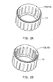
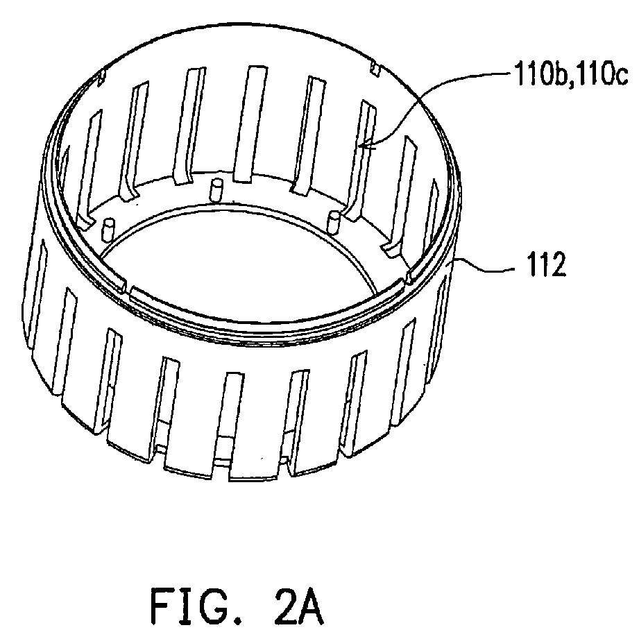
- Fig.2A is a diagram of the first cap body having air inlets without barricade or air outlets without barricade;
- Fig.2B is a diagram of the first cap body having air inlets with barricade or air outlets with barricade;
- Fig.3A is a diagram of the second cap body having air inlets without barricade or air outlets without barricade;
- Fig.3B is a diagram of the second cap body having air inlets with barricade or air outlets with barricade;
- Fig.4 is a diagram of an LED lamp of a second embodiment of the present invention.
- Fig.5A ⁇ Fig.5B are diagrams of relative locations of the fan, the control circuit, the heat sink and the LED light source of a third embodiment of the present invention.
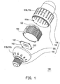
- Fig.1 is a diagram of an LED lamp of a first embodiment of the present invention.
- the LED lamp 100 of the present embodiment includes a lamp housing 110, an LED light source 120, a heat sink 130 and a control circuit 140.
- the lamp housing 110 has an accommodating space 110a, a plurality of air inlets 110b and a plurality of air outlets 110c, and the accommodating space 110a joins the environment through the air inlets 110b and air outlets 110c.
- the LED light source 120 and the heat sink 130 are both disposed in the accommodating space 110a, and the heat sink 130 is connected to the LED light source 120, wherein the heat sink 130 has a pedestal 132 and a plurality of heat dissipation fins 134 connected to the pedestal 132.
- an air convection channel 136 is formed between any two adjacent heat dissipation fins 134, and air from the environment is suitable for flowing into the accommodating space 110a via the air inlets 110b, passing through the air convection channel 136, and leaving the accommodating space 110a via the air outlets 110c sequentially.
- the control circuit 140 is disposed in the accommodating space 110a of the lamp housing 110 and is electrically connected to the LED light source 120.
- the structure of the lamp housing 110, the LED light source 120, the heat sink 130 and the control circuit 140 may have many variations, and the structural design schematically shown in Fig.1 is only illustrated as an example for one skilled in the art to implement the present invention, rather than limiting the scope of the present invention.
- the LED lamp 100 of the present embodiment is an LED light bulb, and the LED lamp may be a light bulb with E27 plug, a light bulb with E26 plug, a light bulb with E14 plug, or light bulbs of other specifications.
- the lamp housing 110 of the present embodiment includes a first cap 112, a lampshade 114, a second cap 116 and a conductive plug 118.
- the lampshade 114 is connected to the first cap 112, and the LED light source 120 is disposed in the lampshade 114.
- the second cap 116 is connected to the first cap 112, so that the first cap 112 is disposed between the lampshade 114 and the second cap 116.
- the conductive plug 118 is connected to the second cap 116, so that the second cap 116 is disposed between the conductive plug 118 and the first cap 112.
- the conductive plug 118 of the present embodiment is an E27 plug, an E26 plug, an E14 plug, or plugs of other specifications, for example.
- the first cap 112 and the second cap 116 are usually fabricated with insulation material (such as plastic) to ensure safety of users.
- insulation material such as plastic
- the present invention does not limit that the first cap 112 and the second cap 116 have to be fabricated with the same insulation material.
- the first cap 112 and the second cap 116 may also be fabricated with conductive material according to different design requirements.
- the material of the first cap 112 and the second cap 116 may be insulation material with doped zinc oxide. Since the insulation material with doped zinc oxide has function of Electro-Magnetic Interference shielding (EMI shielding), the first cap 112 and the second cap 116 with doped zinc oxide are capable of shielding the electromagnetic wave generated from the LED lamp 100, such that harm resulted from the electromagnetic wave can be reduced.
- the first cap 112 and the second cap 116 may be fabricated by injection molding, and deformation of the first cap 112 and the second cap 116 made by the insulation material with doped zinc oxide can be effectively controlled after the first cap 112 and the second cap 116 are released from a mold. Therefore, the yield rate of the first cap 112 and the second cap 116 can be increased.
- EMI shielding Electro-Magnetic Interference shielding
- the LED light source 120 is an LED package fabricated by a packaging process, and the package may be a SMD type package or other type of package.
- the LED light source 120 may be bonded with the heat sink 130 with solder material, so that the heat generated by the LED light source 120 can be effectively conducted to the heat sink 130.
- the present embodiment may also use thermal paste together with screw to perform the bonding between the LED light source 120 and the heat sink 130.
- the heat sink 130 may be fabricated with a single material or a plurality of materials.
- the pedestal 132 and the heat dissipation fins 134 of the heat sink 130 may be fabricated with the same or different materials.
- the material of the heat sink 130 may be copper, aluminum, alloy, or other material with high thermal conductivity.
- the control circuit 140 is a circuit board independent from the LED light source 120.
- the circuit board may be a circuit board with single circuit layer or a circuit board with a plurality of circuit layers. In order to facilitate air convection in the accommodating space 110a, at least one through hole 142 may be fabricated on the circuit board.
- the control circuit 140 may be a chip. When the control circuit 140 is a chip, the control circuit 140 may be integrated into the LED light source 120 to reduce the overall volume occupied by the LED lamp. Moreover, when the control circuit 140 is a chip, the control circuit 140 may also be integrated into the circuit board in the LED light source 120.
- the air inlets 110b and the air outlets 110c formed on the lamp housing 110 are defined according to the convection direction of the air in the accommodating space 110a.
- the openings on the first cap 112 are defined as the air inlets 110b (as shown in Fig.2A and Fig.2B ), and the openings on the second cap 116 are defined as the air outlets 110c (as shown in Fig.3A and Fig.3B ).
- the openings on the first cap 112 are defined as the air outlets 110c (as shown in Fig.2A and Fig.2B ), and the openings on the second cap 116 are defined as the air inlets 110b (as shown in Fig.3A and Fig.3B ).
- the openings on the first cap 112 may be slot-shaped openings (slot-shaped air inlets or slot-shaped air outlets).
- the slot-shaped openings may be arranged in grating. Additionally, each of the slot-shaped openings is corresponding to one of the air convection channels 136 of the heat sink. Such design facilitates heat dissipation performance of the LED lamp 100.
- Fig.2A is a diagram of the first cap body having air inlets without barricade or air outlets without barricade
- Fig.2B is a diagram of the first cap body having air inlets with barricade or air outlets with barricade.
- the air inlets 110b or the air outlets 110c are so-called open type air inlets 110b or open type air outlets 110c (as shown in Fig.2A ); if a user cannot directly observe the inside of the first cap 112 through the air inlets 110b or the air outlets 110c, the air inlets 110b or the air outlets 110c are so-called semi-open type air inlets 110b or semi-open type air outlets 110c (as shown in Fig.2B ).
- Fig.3A is a diagram of the second cap body having air inlets without barricade or air outlets without barricade
- Fig.3B is a diagram of the second cap body having air inlets with barricade or air outlets with barricade
- the air inlets 110b or air outlets 110c are so-called open type air inlets 110b or open type air outlets 110c (as shown in Fig.3A ); if a user cannot directly observe the inside of the second cap 116 through the air inlets 110b or the air outlets 110c, the air inlets 110b or air outlets 110c are so-called semi-open type air inlets 110b or semi-open type air outlets 110c (as shown in Fig.3B ).
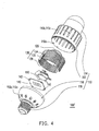
- Fig.4 is a diagram of an LED lamp of the second embodiment of the present invention.
- the LED lamp 100' of the present embodiment is similar to the LED lamp 100 illustrated in the first embodiment except that the LED lamp 100' of the present embodiment further includes a fan 150 disposed in the accommodating space 110a, wherein the air from the environment is driven by the fan 150 to flow into the accommodating space 110a via the air inlets 110b, pass through the air convection channels 136, and leave the accommodating space 110a via the air outlets 110c in sequence.
- the fan 150 is disposed on the pedestal 132, and the fan 150 is surrounded by the heat dissipation fins 134.
- the fan 150 When the fan 150 is turned on, the air convection in the accommodating space 110a is boosted, so that the LED lamp 100' can operate under a lower temperature. It is noted that, in the present embodiment, the fan 150 and the LED light source 120 are disposed on two opposite sides of the pedestal 132, respectively.
- Fig.5A ⁇ Fig.5B are diagrams of relative locations of the fan, the control circuit, the heat sink and the LED light source of the third embodiment of the present invention.
- the present embodiment is similar to the second embodiment.
- the heat sink 130 has a first trench or recess 130a on one side to accommodate the LED light source 120.
- the control circuit 140 e.g. circuit board
- the control circuit 140 is disposed on an opposite side of the heat sink 130.
- the control circuit 140 is disposed between the fan 150 and the heat sink 130.
- the LED light source 120 may be bonded on the heat sink 130 with solder material, so that the heat generated by the LED light source 120 can be effectively conducted to the heat sink 130. Additionally, the present embodiment may also use thermal paste together with screw to perform the bonding between the LED light source 120 and the heat sink 130.
- the heat sink 130 used in the present embodiment may have a second trench or recess 130b (as shown in Fig.5B ) to accommodate the control circuit 140.
- the second trench 130b can not only reduce the overall volume, but also allows the fan 150 to be closer to the heat sink 130, so as to have a better heat dissipation performance.
- the arrangement of the components of the LED lamp in the present invention may change in accordance with different design requirements.
- the above embodiment of the present invention is not used to limit the arrangement of components.
- the present invention uses the heat sink built in the LED lamp to dissipate heat generated therefrom, such that the operation temperature of LED lamp can be effectively maintained within an acceptable range. Therefore, the life span of LED lamp is prolonged.
Abstract
Description
- The present invention relates to a light-emitting diode lamp (LED lamp), more particularly, relates to an LED lamp with good heat dissipation performance.
- LEDs are semiconductor devices. The light emitting chips are mainly made of a compound semiconductor material containing III-V group chemical elements, for example, GaP, GaAs, and the like, and function on the principle of converting electric energy to light. That is to say, the compound semiconductor is powered to release excess energy through the combination of electrons and holes, so as to emit photon (light). An LED can emit light without being heated or does not discharge to emit light. Therefore, the lifespan of the LED is up to 100,000 hours, and an idling time is not required. In addition, the LED has advantages of quick response speed (approximately 10-9 seconds), small volume, power-saving, low pollution, high reliability, and ease of mass production. Thus, LEDs have been intensively used in many fields, for example, as a light source and an illumination device in large-scale bulletin boards, traffic lights, cellular phones, scanners, fax machines, etc.
- Currently, the light emitting brightness and efficiency of LEDs are being continuously improved, and meanwhile white LEDs with high brightness are successfully put into mass production, so the white LEDs have been gradually used in illumination devices such as indoor illumination and outdoor street lamp. Generally, heat dissipation performance is important to high power LEDs. If LEDs operate under high temperature, the brightness that the LED light can provide may be reduced and the life span thereof is reduced. Therefore, how to enhance heat dissipation performance of LEDs is an important topic for research and development.
- The present invention provided an LED with good heat dissipation performance and long life span.
- The present invention provides an LED including a lamp housing, an LED light source, a heat sink and a control circuit. The lamp housing has an accommodating space, a plurality of air inlets and a plurality of air outlets, and the accommodating space joins an environment through the air inlets and air outlets. The LED light source and the heat sink are disposed in the accommodating space, and the heat sink is connected to the LED light source, wherein the heat sink includes a pedestal and a plurality of heat dissipation fins connected to the pedestal. There is an air convection channel between any two adjacent heat dissipation fins. An air convection channel is located between any two adjacent heat dissipation fins, wherein air from the environment is suitable for flowing into the accommodating space via the air inlets, passing through the air convection channels, and leaving the accommodating space via the air outlets . The control circuit is disposed in the lamp housing and is electrically connected to the LED light source.
- In an embodiment of the present invention, the lamp housing includes a first cap, a lampshade, a second cap and a conductive plug for accommodating the heat sink. The lampshade is connected to the first cap, and the LED light source is disposed in the lampshade. The second cap is connected to the first cap, so that the first cap is disposed between the lampshade and the second cap. The plug is connected to the second cap, so that the second cap is disposed between the conductive plug and the first cap.
- In an embodiment of the present invention, the material of the first cap includes insulation material, such as insulation material with doped zinc oxide.
- In an embodiment of the present invention, the material of the second cap includes insulation material, such as insulation material with doped zinc oxide.
- In an embodiment of the present invention, the first cap has air inlets, and the second cap has air outlets, wherein each of the air inlets may be an opening with or without barricade, while each of the air outlets may be an opening with or without barricade.
- In an embodiment of the present invention, each of the air inlets is a slot-shaped air inlet, and the slot-shaped air inlets are arranged in a grating. In addition, each of the slot-shaped air inlets is corresponding to one of the air convection channels of the heat sink, respectively.
- In an embodiment of the present invention, the first cap has air outlets, and the second cap has air inlets, wherein each of the air inlets may be an opening with or without barricade, while each of the air outlets may be an opening with or without barricade.
- In an embodiment of the present invention, each of the air outlets is a slot-shaped air inlet, and the slot-shaped air outlets are arranged in a grating. In addition, each of the slot-shaped air outlets is corresponding to one of the air convection channels of the heat sink, respectively.
- In an embodiment of the present invention, the LED light source is an LED package, or other types of LED light source.
- In an embodiment of the present invention, the materials of the pedestal and heat dissipation fins are the same or different from each other.
- In an embodiment of the present invention, the control circuit is a circuit board.
- In an embodiment of the present invention, the above circuit board has at least a through hole allowing air to flow within the accommodating space.
- In an embodiment of the present invention, the LED lamp may further include a fan disposed in the accommodating space, wherein the air from the environment is driven by the fan to flow into the accommodating space via the air inlets, pass through the air convection channels, and leave the accommodating space via the air outlets in sequence.
- In an embodiment of the present invention, the fan is disposed on the pedestal, and the fan is surrounded by the heat dissipation fins.
- In an embodiment of the present invention, the fan and the LED light source are disposed on two opposite sides of the pedestal, respectively.
- Heat generated from the LED lamp of the present invention is capable of being removed by the built-in heat sink and air convection such that the operation temperature of the LED lamp can be maintained within an acceptable range. In other words, the LED lamp of the present invention is not damaged due to over-heating.
- In order to the make the aforementioned and other objects, features and advantages of the present invention comprehensible, preferred embodiments accompanied with figures are described in detail below.
-
Fig.1 is a diagram of an LED lamp of the first embodiment of the present invention; -
Fig.2A is a diagram of the first cap body having air inlets without barricade or air outlets without barricade; -
Fig.2B is a diagram of the first cap body having air inlets with barricade or air outlets with barricade; -
Fig.3A is a diagram of the second cap body having air inlets without barricade or air outlets without barricade; -
Fig.3B is a diagram of the second cap body having air inlets with barricade or air outlets with barricade; -
Fig.4 is a diagram of an LED lamp of a second embodiment of the present invention; and -
Fig.5A∼Fig.5B are diagrams of relative locations of the fan, the control circuit, the heat sink and the LED light source of a third embodiment of the present invention. -
Fig.1 is a diagram of an LED lamp of a first embodiment of the present invention. With reference toFig.1 , theLED lamp 100 of the present embodiment includes alamp housing 110, anLED light source 120, aheat sink 130 and acontrol circuit 140. Thelamp housing 110 has anaccommodating space 110a, a plurality ofair inlets 110b and a plurality ofair outlets 110c, and theaccommodating space 110a joins the environment through theair inlets 110b andair outlets 110c. TheLED light source 120 and theheat sink 130 are both disposed in theaccommodating space 110a, and theheat sink 130 is connected to theLED light source 120, wherein theheat sink 130 has apedestal 132 and a plurality of heat dissipation fins 134 connected to thepedestal 132. As shown inFig.4 anair convection channel 136 is formed between any two adjacent heat dissipation fins 134, and air from the environment is suitable for flowing into theaccommodating space 110a via theair inlets 110b, passing through theair convection channel 136, and leaving theaccommodating space 110a via theair outlets 110c sequentially. In addition, thecontrol circuit 140 is disposed in theaccommodating space 110a of thelamp housing 110 and is electrically connected to theLED light source 120. - The structure of the
lamp housing 110, theLED light source 120, theheat sink 130 and thecontrol circuit 140 may have many variations, and the structural design schematically shown inFig.1 is only illustrated as an example for one skilled in the art to implement the present invention, rather than limiting the scope of the present invention. - As shown in
Fig.1 , theLED lamp 100 of the present embodiment is an LED light bulb, and the LED lamp may be a light bulb with E27 plug, a light bulb with E26 plug, a light bulb with E14 plug, or light bulbs of other specifications. Specifically, thelamp housing 110 of the present embodiment includes afirst cap 112, alampshade 114, asecond cap 116 and aconductive plug 118. Thelampshade 114 is connected to thefirst cap 112, and theLED light source 120 is disposed in thelampshade 114. Thesecond cap 116 is connected to thefirst cap 112, so that thefirst cap 112 is disposed between thelampshade 114 and thesecond cap 116. In addition, theconductive plug 118 is connected to thesecond cap 116, so that thesecond cap 116 is disposed between theconductive plug 118 and thefirst cap 112. Theconductive plug 118 of the present embodiment is an E27 plug, an E26 plug, an E14 plug, or plugs of other specifications, for example. - Generally, the
first cap 112 and thesecond cap 116 are usually fabricated with insulation material (such as plastic) to ensure safety of users. However, the present invention does not limit that thefirst cap 112 and thesecond cap 116 have to be fabricated with the same insulation material. Thefirst cap 112 and thesecond cap 116 may also be fabricated with conductive material according to different design requirements. - In an embodiment of the present invention, the material of the
first cap 112 and thesecond cap 116 may be insulation material with doped zinc oxide. Since the insulation material with doped zinc oxide has function of Electro-Magnetic Interference shielding (EMI shielding), thefirst cap 112 and thesecond cap 116 with doped zinc oxide are capable of shielding the electromagnetic wave generated from theLED lamp 100, such that harm resulted from the electromagnetic wave can be reduced. In addition, thefirst cap 112 and thesecond cap 116 may be fabricated by injection molding, and deformation of thefirst cap 112 and thesecond cap 116 made by the insulation material with doped zinc oxide can be effectively controlled after thefirst cap 112 and thesecond cap 116 are released from a mold. Therefore, the yield rate of thefirst cap 112 and thesecond cap 116 can be increased. - As shown in
Fig.1 , the LEDlight source 120 is an LED package fabricated by a packaging process, and the package may be a SMD type package or other type of package. In the present embodiment, the LEDlight source 120 may be bonded with theheat sink 130 with solder material, so that the heat generated by the LEDlight source 120 can be effectively conducted to theheat sink 130. Additionally, the present embodiment may also use thermal paste together with screw to perform the bonding between the LEDlight source 120 and theheat sink 130. - In the present embodiment, the
heat sink 130 may be fabricated with a single material or a plurality of materials. In other words, thepedestal 132 and theheat dissipation fins 134 of theheat sink 130 may be fabricated with the same or different materials. Generally, the material of theheat sink 130 may be copper, aluminum, alloy, or other material with high thermal conductivity. - In the present embodiment, the
control circuit 140 is a circuit board independent from the LEDlight source 120. The circuit board may be a circuit board with single circuit layer or a circuit board with a plurality of circuit layers. In order to facilitate air convection in theaccommodating space 110a, at least one throughhole 142 may be fabricated on the circuit board. In an alternative embodiment of the present invention, thecontrol circuit 140 may be a chip. When thecontrol circuit 140 is a chip, thecontrol circuit 140 may be integrated into theLED light source 120 to reduce the overall volume occupied by the LED lamp. Moreover, when thecontrol circuit 140 is a chip, thecontrol circuit 140 may also be integrated into the circuit board in the LEDlight source 120. - The
air inlets 110b and theair outlets 110c formed on thelamp housing 110 are defined according to the convection direction of the air in theaccommodating space 110a. When the air in theaccommodating space 110a flows towards thesecond cap 116 from thefirst cap 112, the openings on thefirst cap 112 are defined as theair inlets 110b (as shown inFig.2A and Fig.2B ), and the openings on thesecond cap 116 are defined as theair outlets 110c (as shown inFig.3A and Fig.3B ). On the contrary, when the air in theaccommodating space 110a flows towards thefirst cap 112 from thesecond cap 116, the openings on thefirst cap 112 are defined as theair outlets 110c (as shown inFig.2A and Fig.2B ), and the openings on thesecond cap 116 are defined as theair inlets 110b (as shown inFig.3A and Fig.3B ). - With reference to
Fig.1 ,Fig.2A and Fig.2B , the openings on the first cap 112 (theair inlets 110b or theair outlets 110c) may be slot-shaped openings (slot-shaped air inlets or slot-shaped air outlets). In the present embodiment, the slot-shaped openings may be arranged in grating. Additionally, each of the slot-shaped openings is corresponding to one of theair convection channels 136 of the heat sink. Such design facilitates heat dissipation performance of theLED lamp 100. -
Fig.2A is a diagram of the first cap body having air inlets without barricade or air outlets without barricade, andFig.2B is a diagram of the first cap body having air inlets with barricade or air outlets with barricade. With reference toFig.2A and Fig.2B , if a user can directly observe the situations in thefirst cap 112 through theair inlets 110b or theair outlets 110c, theair inlets 110b or theair outlets 110c are so-called opentype air inlets 110b or opentype air outlets 110c (as shown inFig.2A ); if a user cannot directly observe the inside of thefirst cap 112 through theair inlets 110b or theair outlets 110c, theair inlets 110b or theair outlets 110c are so-called semi-opentype air inlets 110b or semi-opentype air outlets 110c (as shown inFig.2B ). -
Fig.3A is a diagram of the second cap body having air inlets without barricade or air outlets without barricade, andFig.3B is a diagram of the second cap body having air inlets with barricade or air outlets with barricade With reference toFig.3A and Fig.3B , similarly, if a user can directly observe the inside of thesecond cap 116 through theair inlets 110b or theair outlets 110c, theair inlets 110b orair outlets 110c are so-called opentype air inlets 110b or opentype air outlets 110c (as shown inFig.3A ); if a user cannot directly observe the inside of thesecond cap 116 through theair inlets 110b or theair outlets 110c, theair inlets 110b orair outlets 110c are so-called semi-opentype air inlets 110b or semi-opentype air outlets 110c (as shown inFig.3B ). -
Fig.4 is a diagram of an LED lamp of the second embodiment of the present invention. With reference toFig.4 , the LED lamp 100' of the present embodiment is similar to theLED lamp 100 illustrated in the first embodiment except that the LED lamp 100' of the present embodiment further includes afan 150 disposed in theaccommodating space 110a, wherein the air from the environment is driven by thefan 150 to flow into theaccommodating space 110a via theair inlets 110b, pass through theair convection channels 136, and leave theaccommodating space 110a via theair outlets 110c in sequence. As shown inFig.4 , thefan 150 is disposed on thepedestal 132, and thefan 150 is surrounded by theheat dissipation fins 134. When thefan 150 is turned on, the air convection in theaccommodating space 110a is boosted, so that the LED lamp 100' can operate under a lower temperature. It is noted that, in the present embodiment, thefan 150 and the LEDlight source 120 are disposed on two opposite sides of thepedestal 132, respectively. -
Fig.5A∼Fig.5B are diagrams of relative locations of the fan, the control circuit, the heat sink and the LED light source of the third embodiment of the present invention. With reference toFig.5A and Fig.5B , the present embodiment is similar to the second embodiment. In the present embodiment, theheat sink 130 has a first trench orrecess 130a on one side to accommodate theLED light source 120. The control circuit 140 (e.g. circuit board) is disposed on an opposite side of theheat sink 130. In addition, as shown inFig.5A and Fig.5B , thecontrol circuit 140 is disposed between thefan 150 and theheat sink 130. In the present embodiment, the LEDlight source 120 may be bonded on theheat sink 130 with solder material, so that the heat generated by the LEDlight source 120 can be effectively conducted to theheat sink 130. Additionally, the present embodiment may also use thermal paste together with screw to perform the bonding between the LEDlight source 120 and theheat sink 130. - It is noted that the
heat sink 130 used in the present embodiment may have a second trench orrecess 130b (as shown inFig.5B ) to accommodate thecontrol circuit 140. As shown inFig.5B , thesecond trench 130b can not only reduce the overall volume, but also allows thefan 150 to be closer to theheat sink 130, so as to have a better heat dissipation performance. - As described above, the arrangement of the components of the LED lamp in the present invention may change in accordance with different design requirements. The above embodiment of the present invention is not used to limit the arrangement of components.
- To sum up, the present invention uses the heat sink built in the LED lamp to dissipate heat generated therefrom, such that the operation temperature of LED lamp can be effectively maintained within an acceptable range. Therefore, the life span of LED lamp is prolonged.
- It will be apparent to those skilled in the art that various modifications and variations can be made to the structure of the present invention without departing from the scope of the invention. In view of the foregoing, it is intended that the present invention cover modifications and variations of this invention provided they fall within the scope of the following claims and their equivalents.
Claims (11)
- A light-emitting diode (LED) lamp, comprising:a lamp housing having an accommodating space, a plurality of air inlets and a plurality of air outlets, wherein the accommodating space joins an environment through the air inlets and air outlets;an LED light source disposed in the accommodating space;a heat sink disposed in the accommodating space and connected to the LED light source, the heat sink comprising a pedestal and a plurality of heat dissipation fins connected to the pedestal, an air convection channel being located between any two adjacent heat dissipation fins, wherein air from the environment is suitable for flowing into the accommodating space via the air inlets, passing through the air convection channels, and leaving the accommodating space via the air outlets in sequence; anda control circuit disposed in the lamp housing and electrically connected to the LED light source.
- A LED lamp according to claim 1, wherein the lamp housing comprises:a first cap for accommodating the heat sink;a lampshade connected to the first cap, wherein the LED light source is disposed in the lampshade;a second cap connected the first cap, wherein the first cap is disposed between the lampshade and the second cap; anda conductive plug connected to the second cap, wherein the second cap is disposed between the conductive plug and the first cap.
- A LED lamp according to claim 2, wherein a material of the first cap comprises zinc oxide doped insulation material.
- A LED lamp according to claim 2, wherein a material of the second cap comprises doped zinc oxide insulation material.
- A LED lamp according to any preceding claim, wherein the first cap has the air inlets, and the second cap has the air outlets.
- A LED lamp according to any of claims 1 to 4, wherein the first cap has the air outlets, and the second cap has the air inlets.
- A LED lamp according to any preceding claim, wherein the control circuit comprises a circuit board.
- A LED lamp according to claim 7, wherein the circuit board comprises at least a through hole.
- A LED lamp according to any preceding claim, further comprising a fan disposed in the accommodating space, wherein the air from the environment is driven by the fan to flow into the accommodating space via the air inlets, pass through the air convection channels, and leave the accommodating space via the air outlets in sequence.
- A LED lamp according to claim 9, wherein the fan is disposed on the pedestal and the fan is surrounded by the heat dissipation fins.
- A LED lamp according to claim 9 or claim 10, wherein the fan and the LED light source are disposed on two opposite sides of the pedestal, respectively.
Applications Claiming Priority (1)
| Application Number | Priority Date | Filing Date | Title |
|---|---|---|---|
| CN2007101411631A CN101368719B (en) | 2007-08-13 | 2007-08-13 | LED lamp |
Publications (3)
| Publication Number | Publication Date |
|---|---|
| EP2025992A2 true EP2025992A2 (en) | 2009-02-18 |
| EP2025992A3 EP2025992A3 (en) | 2013-01-30 |
| EP2025992B1 EP2025992B1 (en) | 2014-02-26 |
Family
ID=39735497
Family Applications (1)
| Application Number | Title | Priority Date | Filing Date |
|---|---|---|---|
| EP08251343.3A Not-in-force EP2025992B1 (en) | 2007-08-13 | 2008-04-07 | Light-emitting diode lamp |
Country Status (4)
| Country | Link |
|---|---|
| US (1) | US7874710B2 (en) |
| EP (1) | EP2025992B1 (en) |
| JP (1) | JP4673389B2 (en) |
| CN (1) | CN101368719B (en) |
Cited By (17)
| Publication number | Priority date | Publication date | Assignee | Title |
|---|---|---|---|---|
| EP2175196A1 (en) * | 2008-10-13 | 2010-04-14 | Hyundai Telecommunication Co., Ltd. | Heat dissipation member having variable heat dissipation paths and led lighting flood lamp using the same |
| EP2206951A1 (en) * | 2008-12-26 | 2010-07-14 | Everlight Electronics Co., Ltd. | Heat dissipation device and luminaire comprising the same |
| EP2221523A1 (en) * | 2009-02-23 | 2010-08-25 | Taiwan Green Point Enterprises Co., Ltd. | High efficiency light emitting diode apparatus |
| WO2010128419A1 (en) * | 2009-05-04 | 2010-11-11 | Koninklijke Philips Electronics N.V. | Light source comprising a light emitter arranged inside a translucent outer envelope |
| WO2010145925A1 (en) * | 2009-06-15 | 2010-12-23 | Osram Gesellschaft mit beschränkter Haftung | Cooling member for semiconductor light emitting elements |
| EP2306083A1 (en) * | 2009-10-02 | 2011-04-06 | Everlight Electronics Co., Ltd. | Illumination device |
| EP2306067A3 (en) * | 2009-09-30 | 2012-04-11 | Everlight Electronics Co. Ltd. | Light source module |
| WO2012168845A1 (en) * | 2011-06-06 | 2012-12-13 | Koninklijke Philips Electronics N.V. | Remote heat sink |
| EP2538133A1 (en) * | 2011-06-23 | 2012-12-26 | Koninklijke Philips Electronics N.V. | Remote heat sink |
| CN102900982A (en) * | 2012-10-09 | 2013-01-30 | 佛山市顺德区保利达电器有限公司 | Light emitting diode (LED) lamp bulb |
| EP2383512A3 (en) * | 2010-04-27 | 2013-05-15 | Advanced-Connectek Inc. | Heat dissipation assisting apparatus for a lamp |
| EP2597352A1 (en) * | 2010-06-23 | 2013-05-29 | CCS Inc. | Led light source |
| EP2644985A1 (en) * | 2012-03-26 | 2013-10-02 | Toshiba Lighting & Technology Corporation | Lighting device |
| CN103697344A (en) * | 2012-09-27 | 2014-04-02 | 建准电机工业股份有限公司 | Lamp fitting |
| US8967837B2 (en) | 2013-08-01 | 2015-03-03 | 3M Innovative Properties Company | Solid state light with features for controlling light distribution and air cooling channels |
| US9267674B2 (en) | 2013-10-18 | 2016-02-23 | 3M Innovative Properties Company | Solid state light with enclosed light guide and integrated thermal guide |
| US9354386B2 (en) | 2013-10-25 | 2016-05-31 | 3M Innovative Properties Company | Solid state area light and spotlight with light guide and integrated thermal guide |
Families Citing this family (186)
| Publication number | Priority date | Publication date | Assignee | Title |
|---|---|---|---|---|
| US9412926B2 (en) | 2005-06-10 | 2016-08-09 | Cree, Inc. | High power solid-state lamp |
| US8444299B2 (en) * | 2007-09-25 | 2013-05-21 | Enertron, Inc. | Dimmable LED bulb with heatsink having perforated ridges |
| WO2009071110A1 (en) * | 2007-12-07 | 2009-06-11 | Osram Gesellschaft mit beschränkter Haftung | Heat sink and lighting device comprising a heat sink |
| US8118447B2 (en) | 2007-12-20 | 2012-02-21 | Altair Engineering, Inc. | LED lighting apparatus with swivel connection |
| US7712918B2 (en) | 2007-12-21 | 2010-05-11 | Altair Engineering , Inc. | Light distribution using a light emitting diode assembly |
| US8926138B2 (en) * | 2008-05-13 | 2015-01-06 | Express Imaging Systems, Llc | Gas-discharge lamp replacement |
| US8360599B2 (en) | 2008-05-23 | 2013-01-29 | Ilumisys, Inc. | Electric shock resistant L.E.D. based light |
| US20090303736A1 (en) * | 2008-06-06 | 2009-12-10 | Hsu-Li Yen | Heat-dissipation gain structure of matrix LED light |
| CN101619822B (en) * | 2008-06-30 | 2012-12-19 | 鸿富锦精密工业(深圳)有限公司 | Lighting device |
| US7976196B2 (en) | 2008-07-09 | 2011-07-12 | Altair Engineering, Inc. | Method of forming LED-based light and resulting LED-based light |
| US7575346B1 (en) * | 2008-07-22 | 2009-08-18 | Sunonwealth Electric Machine Industry Co., Ltd. | Lamp |
| US7946729B2 (en) | 2008-07-31 | 2011-05-24 | Altair Engineering, Inc. | Fluorescent tube replacement having longitudinally oriented LEDs |
| US8334640B2 (en) * | 2008-08-13 | 2012-12-18 | Express Imaging Systems, Llc | Turbulent flow cooling for electronic ballast |
| US8674626B2 (en) | 2008-09-02 | 2014-03-18 | Ilumisys, Inc. | LED lamp failure alerting system |
| TWI349085B (en) * | 2008-09-09 | 2011-09-21 | Sunonwealth Electr Mach Ind Co | Lamp |
| US8256924B2 (en) | 2008-09-15 | 2012-09-04 | Ilumisys, Inc. | LED-based light having rapidly oscillating LEDs |
| US7938562B2 (en) | 2008-10-24 | 2011-05-10 | Altair Engineering, Inc. | Lighting including integral communication apparatus |
| US8324817B2 (en) | 2008-10-24 | 2012-12-04 | Ilumisys, Inc. | Light and light sensor |
| US8901823B2 (en) | 2008-10-24 | 2014-12-02 | Ilumisys, Inc. | Light and light sensor |
| US8444292B2 (en) | 2008-10-24 | 2013-05-21 | Ilumisys, Inc. | End cap substitute for LED-based tube replacement light |
| US8214084B2 (en) | 2008-10-24 | 2012-07-03 | Ilumisys, Inc. | Integration of LED lighting with building controls |
| US8653984B2 (en) | 2008-10-24 | 2014-02-18 | Ilumisys, Inc. | Integration of LED lighting control with emergency notification systems |
| US20100226139A1 (en) * | 2008-12-05 | 2010-09-09 | Permlight Products, Inc. | Led-based light engine |
| US8556452B2 (en) | 2009-01-15 | 2013-10-15 | Ilumisys, Inc. | LED lens |
| US8362710B2 (en) | 2009-01-21 | 2013-01-29 | Ilumisys, Inc. | Direct AC-to-DC converter for passive component minimization and universal operation of LED arrays |
| US8664880B2 (en) | 2009-01-21 | 2014-03-04 | Ilumisys, Inc. | Ballast/line detection circuit for fluorescent replacement lamps |
| JP4813582B2 (en) * | 2009-01-30 | 2011-11-09 | 株式会社 近藤工芸 | LED lamp |
| JP2010203509A (en) | 2009-03-03 | 2010-09-16 | Ishikawa Gasket Co Ltd | Metal laminate type cylinder head gasket |
| CN101509653B (en) * | 2009-03-09 | 2015-01-14 | 张春涛 | High power LED lamp structure with fan |
| US8057075B2 (en) * | 2009-03-13 | 2011-11-15 | Sunonwealth Electric Machine Industry Co., Ltd. | Lamp device |
| TWI366645B (en) * | 2009-03-24 | 2012-06-21 | Young Green Energy Co | Illumination apparatus |
| KR100961840B1 (en) * | 2009-10-30 | 2010-06-08 | 화우테크놀러지 주식회사 | Led lamp |
| CN101858499B (en) * | 2009-04-13 | 2012-02-22 | 扬光绿能股份有限公司 | Illumination device |
| CN101858505B (en) * | 2009-04-13 | 2013-04-24 | 富准精密工业(深圳)有限公司 | Light-emitting diode (LED) lamp |
| CN101865372A (en) * | 2009-04-20 | 2010-10-20 | 富准精密工业(深圳)有限公司 | Light-emitting diode lamp |
| US8926139B2 (en) * | 2009-05-01 | 2015-01-06 | Express Imaging Systems, Llc | Gas-discharge lamp replacement with passive cooling |
| US8330381B2 (en) * | 2009-05-14 | 2012-12-11 | Ilumisys, Inc. | Electronic circuit for DC conversion of fluorescent lighting ballast |
| WO2010133021A1 (en) * | 2009-05-19 | 2010-11-25 | Tung Kuo-Feng | Led lamp assembly |
| US8299695B2 (en) * | 2009-06-02 | 2012-10-30 | Ilumisys, Inc. | Screw-in LED bulb comprising a base having outwardly projecting nodes |
| TWI411142B (en) * | 2009-06-23 | 2013-10-01 | Delta Electronics Inc | Illuminating device and packaging method thereof |
| WO2011005579A2 (en) | 2009-06-23 | 2011-01-13 | Altair Engineering, Inc. | Illumination device including leds and a switching power control system |
| US8123379B2 (en) * | 2009-06-24 | 2012-02-28 | Chen Kai-Po | Lighting device with sensor |
| JP5711730B2 (en) * | 2009-06-25 | 2015-05-07 | コーニンクレッカ フィリップス エヌ ヴェ | Thermal management device |
| CN101929625A (en) * | 2009-06-25 | 2010-12-29 | 富准精密工业(深圳)有限公司 | Light emitting diode (LED) lamp |
| WO2011005314A2 (en) * | 2009-07-06 | 2011-01-13 | Rodriquez Edward T | Cooling solid state high-brightness white-light illumination sources |
| US20110026264A1 (en) * | 2009-07-29 | 2011-02-03 | Reed William G | Electrically isolated heat sink for solid-state light |
| US20110037367A1 (en) * | 2009-08-11 | 2011-02-17 | Ventiva, Inc. | Solid-state light bulb having ion wind fan and internal heat sinks |
| TWM374022U (en) * | 2009-08-19 | 2010-02-11 | Paragon Sc Lighting Tech Co | Structure of LED lamp with integrally-formed shape |
| TW201109578A (en) * | 2009-09-09 | 2011-03-16 | Elements Performance Materials Ltd | Heat dissipation structure of lamp |
| TW201109579A (en) * | 2009-09-15 | 2011-03-16 | Advanced Connectek Inc | Structure of LED lamp |
| CN102032473A (en) * | 2009-09-29 | 2011-04-27 | 富士迈半导体精密工业(上海)有限公司 | Light-emitting diode (LED) illumination device |
| TWI385344B (en) * | 2009-10-20 | 2013-02-11 | Foxsemicon Integrated Tech Inc | Led illumination device |
| US9030120B2 (en) * | 2009-10-20 | 2015-05-12 | Cree, Inc. | Heat sinks and lamp incorporating same |
| US9217542B2 (en) | 2009-10-20 | 2015-12-22 | Cree, Inc. | Heat sinks and lamp incorporating same |
| US9243758B2 (en) * | 2009-10-20 | 2016-01-26 | Cree, Inc. | Compact heat sinks and solid state lamp incorporating same |
| CN102042498B (en) * | 2009-10-22 | 2013-09-04 | 建准电机工业股份有限公司 | Lamp |
| KR100975528B1 (en) | 2009-11-26 | 2010-08-12 | 정준호 | Led light |
| CN102109105B (en) * | 2009-12-30 | 2012-07-04 | 广州南科集成电子有限公司 | Multi-aspect luminous high-power LED (light emitting diode) lamp bulb |
| US9068733B2 (en) * | 2010-01-09 | 2015-06-30 | David M. Medinis | LED lamp with actively cooled heat sink |
| JP5354209B2 (en) * | 2010-01-14 | 2013-11-27 | 東芝ライテック株式会社 | Light bulb shaped lamp and lighting equipment |
| US20110181165A1 (en) * | 2010-01-22 | 2011-07-28 | Shun-Tian Lin | Light emitting diode lamp |
| CN101761812B (en) * | 2010-02-10 | 2011-08-03 | 周成凤 | Lamp tube type LED lamp |
| TW201128116A (en) * | 2010-02-11 | 2011-08-16 | Jia-Ye Wu | LED lamp set |
| CN102155636A (en) * | 2010-02-11 | 2011-08-17 | 亿光电子工业股份有限公司 | Light source module and heat dissipation block |
| US9310030B2 (en) | 2010-03-03 | 2016-04-12 | Cree, Inc. | Non-uniform diffuser to scatter light into uniform emission pattern |
| US8632196B2 (en) | 2010-03-03 | 2014-01-21 | Cree, Inc. | LED lamp incorporating remote phosphor and diffuser with heat dissipation features |
| US8562161B2 (en) | 2010-03-03 | 2013-10-22 | Cree, Inc. | LED based pedestal-type lighting structure |
| US8931933B2 (en) * | 2010-03-03 | 2015-01-13 | Cree, Inc. | LED lamp with active cooling element |
| US9625105B2 (en) | 2010-03-03 | 2017-04-18 | Cree, Inc. | LED lamp with active cooling element |
| US10359151B2 (en) | 2010-03-03 | 2019-07-23 | Ideal Industries Lighting Llc | Solid state lamp with thermal spreading elements and light directing optics |
| US9062830B2 (en) * | 2010-03-03 | 2015-06-23 | Cree, Inc. | High efficiency solid state lamp and bulb |
| US20110227102A1 (en) * | 2010-03-03 | 2011-09-22 | Cree, Inc. | High efficacy led lamp with remote phosphor and diffuser configuration |
| US8882284B2 (en) | 2010-03-03 | 2014-11-11 | Cree, Inc. | LED lamp or bulb with remote phosphor and diffuser configuration with enhanced scattering properties |
| US9316361B2 (en) | 2010-03-03 | 2016-04-19 | Cree, Inc. | LED lamp with remote phosphor and diffuser configuration |
| US9024517B2 (en) | 2010-03-03 | 2015-05-05 | Cree, Inc. | LED lamp with remote phosphor and diffuser configuration utilizing red emitters |
| US9275979B2 (en) | 2010-03-03 | 2016-03-01 | Cree, Inc. | Enhanced color rendering index emitter through phosphor separation |
| US9057511B2 (en) | 2010-03-03 | 2015-06-16 | Cree, Inc. | High efficiency solid state lamp and bulb |
| US9500325B2 (en) | 2010-03-03 | 2016-11-22 | Cree, Inc. | LED lamp incorporating remote phosphor with heat dissipation features |
| CN102192489A (en) * | 2010-03-11 | 2011-09-21 | 骆俊光 | Efficient heat radiation device |
| CN101761813A (en) * | 2010-03-22 | 2010-06-30 | 白建国 | LYD lamp with turbulent air radiation |
| US8540401B2 (en) | 2010-03-26 | 2013-09-24 | Ilumisys, Inc. | LED bulb with internal heat dissipating structures |
| WO2011119907A2 (en) | 2010-03-26 | 2011-09-29 | Altair Engineering, Inc. | Led light tube with dual sided light distribution |
| EP2553320A4 (en) | 2010-03-26 | 2014-06-18 | Ilumisys Inc | Led light with thermoelectric generator |
| USD671257S1 (en) * | 2010-04-10 | 2012-11-20 | Lg Innotek Co., Ltd. | LED lamp |
| DE102010028481A1 (en) * | 2010-05-03 | 2011-11-03 | Osram Gesellschaft mit beschränkter Haftung | Electronic housing for a lamp, semiconductor lamp and method for casting an electronics housing for a lamp |
| TWI498506B (en) | 2010-05-23 | 2015-09-01 | Rab Lighting Inc | Led housing with heat transfer sink |
| JP4854798B2 (en) * | 2010-05-31 | 2012-01-18 | シャープ株式会社 | Lighting device |
| US9241401B2 (en) | 2010-06-22 | 2016-01-19 | Express Imaging Systems, Llc | Solid state lighting device and method employing heat exchanger thermally coupled circuit board |
| KR101216084B1 (en) | 2010-06-23 | 2012-12-26 | 엘지전자 주식회사 | Lighting device and module type lighting device |
| JPWO2011162048A1 (en) * | 2010-06-23 | 2013-08-19 | シーシーエス株式会社 | LED light source device |
| KR101053633B1 (en) | 2010-06-23 | 2011-08-03 | 엘지전자 주식회사 | Module type lighting device |
| KR101349841B1 (en) | 2010-06-24 | 2014-01-09 | 엘지전자 주식회사 | LED Lighting Device |
| KR101057064B1 (en) | 2010-06-30 | 2011-08-16 | 엘지전자 주식회사 | Led based lamp and method for manufacturing the same |
| TW201200794A (en) * | 2010-06-30 | 2012-01-01 | Foxsemicon Integrated Tech Inc | LED lamp |
| KR101053634B1 (en) | 2010-07-02 | 2011-08-03 | 엘지전자 주식회사 | Led based lamp and method for manufacturing the same |
| US8454193B2 (en) | 2010-07-08 | 2013-06-04 | Ilumisys, Inc. | Independent modules for LED fluorescent light tube replacement |
| US8360622B2 (en) * | 2010-07-09 | 2013-01-29 | GE Lighting Solutions, LLC | LED light source in incandescent shaped light bulb |
| US8596813B2 (en) | 2010-07-12 | 2013-12-03 | Ilumisys, Inc. | Circuit board mount for LED light tube |
| WO2012012935A1 (en) * | 2010-07-27 | 2012-02-02 | Feng Lin | Heat dissipating device for led light source and led light source |
| US10451251B2 (en) | 2010-08-02 | 2019-10-22 | Ideal Industries Lighting, LLC | Solid state lamp with light directing optics and diffuser |
| TW201207310A (en) * | 2010-08-13 | 2012-02-16 | Foxsemicon Integrated Tech Inc | LED lamp and method for manufacturing a heat sink of the LED lamp |
| TWI408312B (en) * | 2010-10-05 | 2013-09-11 | Sunonwealth Electr Mach Ind Co | Lamp |
| CN101949504A (en) * | 2010-10-20 | 2011-01-19 | 江苏森隆机电有限公司 | Light-emitting diode lamp bulb capable of performing forced convection and cooling |
| US8523394B2 (en) | 2010-10-29 | 2013-09-03 | Ilumisys, Inc. | Mechanisms for reducing risk of shock during installation of light tube |
| CN102003684B (en) * | 2010-11-26 | 2012-05-23 | 北京化工大学 | Heat dissipation structure of high-power light-emitting diode (LED) illuminating lamp |
| US8870415B2 (en) | 2010-12-09 | 2014-10-28 | Ilumisys, Inc. | LED fluorescent tube replacement light with reduced shock hazard |
| CN102563394A (en) * | 2010-12-27 | 2012-07-11 | 富准精密工业(深圳)有限公司 | Light emitting diode (LED) lamp bulb |
| CN102022657A (en) * | 2010-12-28 | 2011-04-20 | 鸿富锦精密工业(深圳)有限公司 | LED (light-emitting diode) illuminating lamp |
| US8905589B2 (en) | 2011-01-12 | 2014-12-09 | Kenall Manufacturing Company | LED luminaire thermal management system |
| US9752769B2 (en) | 2011-01-12 | 2017-09-05 | Kenall Manufacturing Company | LED luminaire tertiary optic system |
| DE102011008613B4 (en) * | 2011-01-14 | 2016-10-20 | Osram Gmbh | lighting device |
| US9068701B2 (en) | 2012-01-26 | 2015-06-30 | Cree, Inc. | Lamp structure with remote LED light source |
| US9234655B2 (en) | 2011-02-07 | 2016-01-12 | Cree, Inc. | Lamp with remote LED light source and heat dissipating elements |
| US11251164B2 (en) | 2011-02-16 | 2022-02-15 | Creeled, Inc. | Multi-layer conversion material for down conversion in solid state lighting |
| JP5296122B2 (en) | 2011-02-28 | 2013-09-25 | 株式会社東芝 | Lighting device |
| TWI409405B (en) * | 2011-03-09 | 2013-09-21 | Amtran Technology Co Ltd | Light emitting device |
| US8459846B2 (en) * | 2011-03-14 | 2013-06-11 | Artled Technology Corp. | Heat-dissipating downlight lamp holder |
| CN102679188B (en) * | 2011-03-15 | 2014-01-29 | 瑞轩科技股份有限公司 | Light-emitting device |
| TWI426214B (en) * | 2011-03-15 | 2014-02-11 | Sunonwealth Electr Mach Ind Co | Lamp |
| CN102691948B (en) * | 2011-03-23 | 2016-04-20 | 欧司朗股份有限公司 | Can the Down lamp of multi-direction regulating irradiation angle |
| TWM441089U (en) * | 2011-04-11 | 2012-11-11 | Molex Inc | LED Lamp |
| US10030863B2 (en) | 2011-04-19 | 2018-07-24 | Cree, Inc. | Heat sink structures, lighting elements and lamps incorporating same, and methods of making same |
| KR101215779B1 (en) | 2011-05-18 | 2013-01-09 | 정현종 | Replective led light apparatus equipped with fan |
| TWI408313B (en) * | 2011-05-23 | 2013-09-11 | Sunonwealth Electr Mach Ind Co | Led lamp |
| KR101131502B1 (en) | 2011-05-26 | 2012-04-04 | 남경훈 | Device for radiate |
| TWM415248U (en) * | 2011-06-08 | 2011-11-01 | Wellypower Optronics Corp | Structure of bubble lamp |
| US8740415B2 (en) * | 2011-07-08 | 2014-06-03 | Switch Bulb Company, Inc. | Partitioned heatsink for improved cooling of an LED bulb |
| US8926140B2 (en) | 2011-07-08 | 2015-01-06 | Switch Bulb Company, Inc. | Partitioned heatsink for improved cooling of an LED bulb |
| KR101075189B1 (en) | 2011-07-14 | 2011-10-19 | (주)링크옵틱스 | Bulb type led lamp for light culture |
| KR101129524B1 (en) * | 2011-07-22 | 2012-03-29 | 마레티 홀딩 비브이 | Led lamp module have function of radiating heat and led lighting apparatus with led lamp |
| US8911117B2 (en) | 2011-07-26 | 2014-12-16 | Mike Hulsman | LED lighting apparatus with a high efficiency convective heat sink |
| CN102235610A (en) * | 2011-08-16 | 2011-11-09 | 彭雯 | LED (light emitting diode) ball bulb |
| US9072171B2 (en) | 2011-08-24 | 2015-06-30 | Ilumisys, Inc. | Circuit board mount for LED light |
| KR101876948B1 (en) * | 2011-08-24 | 2018-07-10 | 엘지이노텍 주식회사 | Illuminating lamp |
| CN102374427A (en) * | 2011-09-20 | 2012-03-14 | 浙江捷莱照明有限公司 | LED (light-emitting diode) bulb lamp |
| CN102313179B (en) * | 2011-09-30 | 2013-03-13 | 邓旭恒 | Super-miniature high-power light emitting diode (LED) energy-saving quartz lamp |
| TWM423207U (en) * | 2011-10-13 | 2012-02-21 | Yi-Ming Chen | Heat-dissipation structure for light bulb |
| US10378749B2 (en) | 2012-02-10 | 2019-08-13 | Ideal Industries Lighting Llc | Lighting device comprising shield element, and shield element |
| WO2013131002A1 (en) | 2012-03-02 | 2013-09-06 | Ilumisys, Inc. | Electrical connector header for an led-based light |
| US9488359B2 (en) | 2012-03-26 | 2016-11-08 | Cree, Inc. | Passive phase change radiators for LED lamps and fixtures |
| KR101414650B1 (en) * | 2012-05-09 | 2014-07-03 | 엘지전자 주식회사 | Lighting apparatus |
| CN102679222B (en) * | 2012-05-19 | 2014-08-06 | 广州欧科廷光电照明股份有限公司 | LED (light-emitting diode) lamp for radiating heat by using ultrasonic waves |
| CN102721023B (en) * | 2012-06-05 | 2015-04-15 | 余姚天超通风设备有限公司 | LED lamp radiator |
| US9163794B2 (en) | 2012-07-06 | 2015-10-20 | Ilumisys, Inc. | Power supply assembly for LED-based light tube |
| US8994273B2 (en) | 2012-07-09 | 2015-03-31 | Mp Design Inc. | Light-emitting diode fixture with an improved thermal control system |
| US9271367B2 (en) | 2012-07-09 | 2016-02-23 | Ilumisys, Inc. | System and method for controlling operation of an LED-based light |
| CN102818199B (en) * | 2012-07-23 | 2014-12-10 | 贵州光浦森光电有限公司 | LED (Light-Emitting Diode) ceiling lamp |
| CN103574550A (en) * | 2012-07-26 | 2014-02-12 | 通用电气照明解决方案有限责任公司 | Cooling system and illuminating device comprising same |
| KR101978633B1 (en) * | 2012-07-27 | 2019-05-15 | 엘지이노텍 주식회사 | Lighting device |
| CN102966871B (en) * | 2012-08-02 | 2016-01-20 | 福建新文行灯饰有限公司 | A kind of radiating LED lamp |
| CN103629644A (en) * | 2012-08-27 | 2014-03-12 | 欧司朗股份有限公司 | Heat transfer block used for LED device, LED device and LED lamp |
| CN102818160B (en) * | 2012-08-31 | 2015-08-19 | 深圳珈伟光伏照明股份有限公司 | Can air-guiding exchange, heat radiation LED lamp |
| US8622591B1 (en) * | 2012-08-31 | 2014-01-07 | Shenzhen Jiawei Photovoltaic Lighting Co., Ltd. | LED lamp scattering heat by exchanging currents |
| US8764247B2 (en) * | 2012-11-07 | 2014-07-01 | Palo Alto Research Center Incorporated | LED bulb with integrated thermal and optical diffuser |
| US10139097B2 (en) * | 2013-03-04 | 2018-11-27 | Shenzhen Qin Bo Core Technology Development Co., Ltd. | Solid-state light source heat dissipation metal shell and light source engine, the manufacturing methods thereof, and mold |
| US9285084B2 (en) | 2013-03-14 | 2016-03-15 | Ilumisys, Inc. | Diffusers for LED-based lights |
| US9267650B2 (en) | 2013-10-09 | 2016-02-23 | Ilumisys, Inc. | Lens for an LED-based light |
| USD735368S1 (en) | 2013-12-04 | 2015-07-28 | 3M Innovative Properties Company | Solid state light assembly |
| EP3097748A1 (en) | 2014-01-22 | 2016-11-30 | iLumisys, Inc. | Led-based light with addressed leds |
| CN103775878A (en) * | 2014-01-25 | 2014-05-07 | 江苏雷立博光电有限公司 | LED (Light Emitting Diode) lamp capable of easily radiating |
| US10030819B2 (en) * | 2014-01-30 | 2018-07-24 | Cree, Inc. | LED lamp and heat sink |
| US9360188B2 (en) | 2014-02-20 | 2016-06-07 | Cree, Inc. | Remote phosphor element filled with transparent material and method for forming multisection optical elements |
| USD736966S1 (en) | 2014-03-28 | 2015-08-18 | 3M Innovative Properties Company | Solid state light assembly |
| US9510400B2 (en) | 2014-05-13 | 2016-11-29 | Ilumisys, Inc. | User input systems for an LED-based light |
| US9572230B2 (en) | 2014-09-30 | 2017-02-14 | Express Imaging Systems, Llc | Centralized control of area lighting hours of illumination |
| US9445485B2 (en) | 2014-10-24 | 2016-09-13 | Express Imaging Systems, Llc | Detection and correction of faulty photo controls in outdoor luminaires |
| CN104359036B (en) * | 2014-12-01 | 2016-09-14 | 东莞市闻誉实业有限公司 | LED with pipeline |
| CN104613443B (en) * | 2015-02-03 | 2018-01-30 | 东莞市闻誉实业有限公司 | Radiator with guide vane |
| CN104613348B (en) * | 2015-02-03 | 2016-08-24 | 东莞市闻誉实业有限公司 | LED with helical wind-guiding road |
| CN204407360U (en) * | 2015-02-14 | 2015-06-17 | 吴鼎鼎 | A kind of long-life LED luminescence unit and long-life LED |
| USD768316S1 (en) | 2015-04-03 | 2016-10-04 | 3M Innovative Properties Company | Solid state luminaire with dome reflector |
| CN104851956B (en) * | 2015-04-20 | 2017-07-18 | 绍兴文理学院 | A kind of near ultraviolet excited white light LED light source |
| USD780348S1 (en) | 2015-06-01 | 2017-02-28 | Ilumisys, Inc. | LED-based light tube |
| US10161568B2 (en) | 2015-06-01 | 2018-12-25 | Ilumisys, Inc. | LED-based light with canted outer walls |
| USD781469S1 (en) | 2015-07-07 | 2017-03-14 | Ilumisys, Inc. | LED light tube |
| USD815763S1 (en) | 2015-07-07 | 2018-04-17 | Ilumisys, Inc. | LED-based light tube |
| KR20170084502A (en) * | 2016-01-12 | 2017-07-20 | 주식회사 비케이테크놀로지 | Lighting apparatus and heating value controlling method thereof |
| CN105650498A (en) * | 2016-02-29 | 2016-06-08 | 柳州格瑞斯光电科技有限公司 | LED mining lamp |
| US10871282B2 (en) * | 2016-06-23 | 2020-12-22 | Oppie Lighting Co., Ltd. | Illuminator device |
| CA2971938A1 (en) | 2017-01-16 | 2018-07-16 | Lumca Inc. | Led lighting fixture |
| US11375599B2 (en) | 2017-04-03 | 2022-06-28 | Express Imaging Systems, Llc | Systems and methods for outdoor luminaire wireless control |
| US10904992B2 (en) | 2017-04-03 | 2021-01-26 | Express Imaging Systems, Llc | Systems and methods for outdoor luminaire wireless control |
| US10164374B1 (en) | 2017-10-31 | 2018-12-25 | Express Imaging Systems, Llc | Receptacle sockets for twist-lock connectors |
| CN108105676A (en) * | 2017-12-19 | 2018-06-01 | 广西玉林市汉龙环保科技有限公司 | A kind of lampshade rotating device of LED illumination lamp |
| GB2581500B (en) * | 2019-02-19 | 2021-11-17 | Richard Sunderland Thomas | Smart light bulb with integral virtual assistant device |
| TWI717248B (en) * | 2020-03-30 | 2021-01-21 | 正裕起動有限公司 | Lamp structure |
Citations (8)
| Publication number | Priority date | Publication date | Assignee | Title |
|---|---|---|---|---|
| JPH0660705A (en) * | 1991-03-20 | 1994-03-04 | Koito Mfg Co Ltd | Headlamp for automobile |
| US5882108A (en) * | 1995-10-12 | 1999-03-16 | Valeo Sylvania L.L.C. | Lighting with EMI shielding |
| WO2002066889A1 (en) * | 2001-02-16 | 2002-08-29 | Dialight Corporation | Led beacon lamp |
| US20040222516A1 (en) * | 2003-05-07 | 2004-11-11 | Ting-Hao Lin | Light emitting diode bulb having high heat dissipating efficiency |
| US20050174780A1 (en) * | 2004-02-06 | 2005-08-11 | Daejin Dmp Co., Ltd. | LED light |
| GB2420172A (en) * | 2004-11-11 | 2006-05-17 | James Andrew Fowler | Lamp with air cooling and heat sink |
| US20060193139A1 (en) * | 2005-02-25 | 2006-08-31 | Edison Opto Corporation | Heat dissipating apparatus for lighting utility |
| EP1705421A2 (en) * | 2005-03-23 | 2006-09-27 | Nuriplan Co., Ltd. | Led illumination lamp |
Family Cites Families (16)
| Publication number | Priority date | Publication date | Assignee | Title |
|---|---|---|---|---|
| JPH0911155A (en) | 1995-06-23 | 1997-01-14 | Hitachi Koki Co Ltd | Holder for impact tool |
| JP2002110093A (en) * | 2000-07-28 | 2002-04-12 | Toshiba Lighting & Technology Corp | Fluorescent lamp |
| US6746885B2 (en) * | 2001-08-24 | 2004-06-08 | Densen Cao | Method for making a semiconductor light source |
| US6511209B1 (en) * | 2001-10-02 | 2003-01-28 | Albert C. L. Chiang | Lighting fixture |
| WO2003056636A1 (en) * | 2001-12-29 | 2003-07-10 | Hangzhou Fuyang Xinying Dianzi Ltd. | A led and led lamp |
| US7144135B2 (en) * | 2003-11-26 | 2006-12-05 | Philips Lumileds Lighting Company, Llc | LED lamp heat sink |
| US20060120080A1 (en) * | 2004-02-03 | 2006-06-08 | Gene Sipinski | Control and an integrated circuit for a multisensory apparatus |
| US7658510B2 (en) * | 2004-08-18 | 2010-02-09 | Remco Solid State Lighting Inc. | System and method for power control in a LED luminaire |
| US7165866B2 (en) * | 2004-11-01 | 2007-01-23 | Chia Mao Li | Light enhanced and heat dissipating bulb |
| JP2006310057A (en) * | 2005-04-27 | 2006-11-09 | Arumo Technos Kk | Led illumination lamp and led lighting control circuit |
| CN2869562Y (en) * | 2006-01-18 | 2007-02-14 | 吴敏 | Lighting, decorative LED projection lamp |
| CN2881340Y (en) * | 2006-03-03 | 2007-03-21 | 超众科技股份有限公司 | LED lamp and its radiating structure |
| TWM297444U (en) | 2006-03-20 | 2006-09-11 | Jungli Shing Jr | Lamp |
| CN2903668Y (en) * | 2006-04-12 | 2007-05-23 | 深圳市红绿蓝光电科技有限公司 | Wide angle lamp bulb |
| CN2906327Y (en) * | 2006-04-30 | 2007-05-30 | 赵永学 | Heat radiation structure for LED illumination |
| TWM300864U (en) | 2006-05-26 | 2006-11-11 | Jaffe Ltd | Heat-dissipating structure for lamp |
-
2007
- 2007-08-13 CN CN2007101411631A patent/CN101368719B/en not_active Expired - Fee Related
- 2007-10-23 US US11/876,778 patent/US7874710B2/en not_active Expired - Fee Related
-
2008
- 2008-04-07 EP EP08251343.3A patent/EP2025992B1/en not_active Not-in-force
- 2008-04-16 JP JP2008106291A patent/JP4673389B2/en not_active Expired - Fee Related
Patent Citations (8)
| Publication number | Priority date | Publication date | Assignee | Title |
|---|---|---|---|---|
| JPH0660705A (en) * | 1991-03-20 | 1994-03-04 | Koito Mfg Co Ltd | Headlamp for automobile |
| US5882108A (en) * | 1995-10-12 | 1999-03-16 | Valeo Sylvania L.L.C. | Lighting with EMI shielding |
| WO2002066889A1 (en) * | 2001-02-16 | 2002-08-29 | Dialight Corporation | Led beacon lamp |
| US20040222516A1 (en) * | 2003-05-07 | 2004-11-11 | Ting-Hao Lin | Light emitting diode bulb having high heat dissipating efficiency |
| US20050174780A1 (en) * | 2004-02-06 | 2005-08-11 | Daejin Dmp Co., Ltd. | LED light |
| GB2420172A (en) * | 2004-11-11 | 2006-05-17 | James Andrew Fowler | Lamp with air cooling and heat sink |
| US20060193139A1 (en) * | 2005-02-25 | 2006-08-31 | Edison Opto Corporation | Heat dissipating apparatus for lighting utility |
| EP1705421A2 (en) * | 2005-03-23 | 2006-09-27 | Nuriplan Co., Ltd. | Led illumination lamp |
Cited By (22)
| Publication number | Priority date | Publication date | Assignee | Title |
|---|---|---|---|---|
| EP2175196A1 (en) * | 2008-10-13 | 2010-04-14 | Hyundai Telecommunication Co., Ltd. | Heat dissipation member having variable heat dissipation paths and led lighting flood lamp using the same |
| EP2206951A1 (en) * | 2008-12-26 | 2010-07-14 | Everlight Electronics Co., Ltd. | Heat dissipation device and luminaire comprising the same |
| EP2221523A1 (en) * | 2009-02-23 | 2010-08-25 | Taiwan Green Point Enterprises Co., Ltd. | High efficiency light emitting diode apparatus |
| WO2010128419A1 (en) * | 2009-05-04 | 2010-11-11 | Koninklijke Philips Electronics N.V. | Light source comprising a light emitter arranged inside a translucent outer envelope |
| US9175817B2 (en) | 2009-05-04 | 2015-11-03 | Koninklijke Philips N.V. | Light source comprising a light emitter arranged inside a translucent outer envelope |
| WO2010145925A1 (en) * | 2009-06-15 | 2010-12-23 | Osram Gesellschaft mit beschränkter Haftung | Cooling member for semiconductor light emitting elements |
| EP2306067A3 (en) * | 2009-09-30 | 2012-04-11 | Everlight Electronics Co. Ltd. | Light source module |
| EP2306083A1 (en) * | 2009-10-02 | 2011-04-06 | Everlight Electronics Co., Ltd. | Illumination device |
| US8083383B2 (en) | 2009-10-02 | 2011-12-27 | Everlight Electronics Co., Ltd. | Illumination device |
| EP2383512A3 (en) * | 2010-04-27 | 2013-05-15 | Advanced-Connectek Inc. | Heat dissipation assisting apparatus for a lamp |
| EP2597352A4 (en) * | 2010-06-23 | 2014-06-25 | Ccs Inc | Led light source |
| EP2597352A1 (en) * | 2010-06-23 | 2013-05-29 | CCS Inc. | Led light source |
| WO2012168845A1 (en) * | 2011-06-06 | 2012-12-13 | Koninklijke Philips Electronics N.V. | Remote heat sink |
| EP2538133A1 (en) * | 2011-06-23 | 2012-12-26 | Koninklijke Philips Electronics N.V. | Remote heat sink |
| EP2644985A1 (en) * | 2012-03-26 | 2013-10-02 | Toshiba Lighting & Technology Corporation | Lighting device |
| CN103697344A (en) * | 2012-09-27 | 2014-04-02 | 建准电机工业股份有限公司 | Lamp fitting |
| CN103697344B (en) * | 2012-09-27 | 2016-04-06 | 建准电机工业股份有限公司 | Lamp fitting |
| CN102900982A (en) * | 2012-10-09 | 2013-01-30 | 佛山市顺德区保利达电器有限公司 | Light emitting diode (LED) lamp bulb |
| CN102900982B (en) * | 2012-10-09 | 2014-08-13 | 佛山市顺德区保利达电器有限公司 | Light emitting diode (LED) lamp bulb |
| US8967837B2 (en) | 2013-08-01 | 2015-03-03 | 3M Innovative Properties Company | Solid state light with features for controlling light distribution and air cooling channels |
| US9267674B2 (en) | 2013-10-18 | 2016-02-23 | 3M Innovative Properties Company | Solid state light with enclosed light guide and integrated thermal guide |
| US9354386B2 (en) | 2013-10-25 | 2016-05-31 | 3M Innovative Properties Company | Solid state area light and spotlight with light guide and integrated thermal guide |
Also Published As
| Publication number | Publication date |
|---|---|
| CN101368719B (en) | 2011-07-06 |
| JP4673389B2 (en) | 2011-04-20 |
| JP2009048994A (en) | 2009-03-05 |
| EP2025992B1 (en) | 2014-02-26 |
| CN101368719A (en) | 2009-02-18 |
| EP2025992A3 (en) | 2013-01-30 |
| US7874710B2 (en) | 2011-01-25 |
| US20090046473A1 (en) | 2009-02-19 |
Similar Documents
| Publication | Publication Date | Title |
|---|---|---|
| US7874710B2 (en) | Light-emitting diode lamp | |
| US7965029B2 (en) | Light-emitting diode illumination apparatus | |
| US10107487B2 (en) | LED light bulbs | |
| EP2206951A1 (en) | Heat dissipation device and luminaire comprising the same | |
| US20090237933A1 (en) | Led illumination device and light engine thereof | |
| US20100270904A1 (en) | Led bulb with modules having side-emitting diodes | |
| TW200907239A (en) | Light-emitting diode lamp | |
| JP4096927B2 (en) | LED lighting source | |
| US20100271822A1 (en) | Led lamp | |
| CN202140858U (en) | Light-emitting diode (LED) lamp with radiating structure | |
| US8376587B2 (en) | LED illuminating device and light engine thereof | |
| US8419237B2 (en) | Heat sink and light emitting diode lamp | |
| US8333486B2 (en) | Illumination device with heat dissipation structure | |
| KR101981716B1 (en) | Lighting device | |
| TW201437543A (en) | Light emitting diode lamp | |
| CN214468099U (en) | Novel long-life LED lamp pearl | |
| KR101912382B1 (en) | Lighting device | |
| KR101175754B1 (en) | Light emitting device | |
| KR101833223B1 (en) | Lighting device | |
| KR101890186B1 (en) | Lighting device | |
| KR20130023823A (en) | Lighting device | |
| KR20130014756A (en) | Lighting device |
Legal Events
| Date | Code | Title | Description |
|---|---|---|---|
| PUAI | Public reference made under article 153(3) epc to a published international application that has entered the european phase |
Free format text: ORIGINAL CODE: 0009012 |
|
| AK | Designated contracting states |
Kind code of ref document: A2 Designated state(s): AT BE BG CH CY CZ DE DK EE ES FI FR GB GR HR HU IE IS IT LI LT LU LV MC MT NL NO PL PT RO SE SI SK TR |
|
| AX | Request for extension of the european patent |
Extension state: AL BA MK RS |
|
| RAP1 | Party data changed (applicant data changed or rights of an application transferred) |
Owner name: GE INVESTMENT CO., LTD. Owner name: LUSTROUS INTERNATIONAL TECHNOLOGY LTD. |
|
| RAP1 | Party data changed (applicant data changed or rights of an application transferred) |
Owner name: TOP ENERGY SAVING SYSTEM CORP. Owner name: LUSTROUS INTERNATIONAL TECHNOLOGY LTD. |
|
| PUAL | Search report despatched |
Free format text: ORIGINAL CODE: 0009013 |
|
| AK | Designated contracting states |
Kind code of ref document: A3 Designated state(s): AT BE BG CH CY CZ DE DK EE ES FI FR GB GR HR HU IE IS IT LI LT LU LV MC MT NL NO PL PT RO SE SI SK TR |
|
| AX | Request for extension of the european patent |
Extension state: AL BA MK RS |
|
| 17P | Request for examination filed |
Effective date: 20130724 |
|
| RBV | Designated contracting states (corrected) |
Designated state(s): AT BE BG CH CY CZ DE DK EE ES FI FR GB GR HR HU IE IS IT LI LT LU LV MC MT NL NO PL PT RO SE SI SK TR |
|
| REG | Reference to a national code |
Ref country code: DE Ref legal event code: R079 Ref document number: 602008030416 Country of ref document: DE Free format text: PREVIOUS MAIN CLASS: F21K0007000000 Ipc: F21V0029020000 |
|
| AKX | Designation fees paid |
Designated state(s): AT BE BG CH CY CZ DE DK EE ES FI FR GB GR HR HU IE IS IT LI LT LU LV MC MT NL NO PL PT RO SE SI SK TR |
|
| RIC1 | Information provided on ipc code assigned before grant |
Ipc: F21V 29/02 20060101AFI20130912BHEP Ipc: F21K 99/00 20100101ALI20130912BHEP |
|
| GRAP | Despatch of communication of intention to grant a patent |
Free format text: ORIGINAL CODE: EPIDOSNIGR1 |
|
| RAP1 | Party data changed (applicant data changed or rights of an application transferred) |
Owner name: LUSTROUS INTERNATIONAL TECHNOLOGY LTD. Owner name: CHANG WAH ELECTROMATERIALS INC. |
|
| INTG | Intention to grant announced |
Effective date: 20131202 |
|
| RAP1 | Party data changed (applicant data changed or rights of an application transferred) |
Owner name: CHANG WAH ELECTROMATERIALS INC. |
|
| GRAS | Grant fee paid |
Free format text: ORIGINAL CODE: EPIDOSNIGR3 |
|
| GRAA | (expected) grant |
Free format text: ORIGINAL CODE: 0009210 |
|
| AK | Designated contracting states |
Kind code of ref document: B1 Designated state(s): AT BE BG CH CY CZ DE DK EE ES FI FR GB GR HR HU IE IS IT LI LT LU LV MC MT NL NO PL PT RO SE SI SK TR |
|
| REG | Reference to a national code |
Ref country code: GB Ref legal event code: FG4D |
|
| REG | Reference to a national code |
Ref country code: CH Ref legal event code: EP |
|
| REG | Reference to a national code |
Ref country code: AT Ref legal event code: REF Ref document number: 653834 Country of ref document: AT Kind code of ref document: T Effective date: 20140315 |
|
| REG | Reference to a national code |
Ref country code: IE Ref legal event code: FG4D |
|
| REG | Reference to a national code |
Ref country code: DE Ref legal event code: R096 Ref document number: 602008030416 Country of ref document: DE Effective date: 20140410 |
|
| REG | Reference to a national code |
Ref country code: NL Ref legal event code: VDEP Effective date: 20140226 |
|
| REG | Reference to a national code |
Ref country code: AT Ref legal event code: MK05 Ref document number: 653834 Country of ref document: AT Kind code of ref document: T Effective date: 20140226 |
|
| REG | Reference to a national code |
Ref country code: LT Ref legal event code: MG4D |
|
| PG25 | Lapsed in a contracting state [announced via postgrant information from national office to epo] |
Ref country code: IS Free format text: LAPSE BECAUSE OF FAILURE TO SUBMIT A TRANSLATION OF THE DESCRIPTION OR TO PAY THE FEE WITHIN THE PRESCRIBED TIME-LIMIT Effective date: 20140626 Ref country code: LT Free format text: LAPSE BECAUSE OF FAILURE TO SUBMIT A TRANSLATION OF THE DESCRIPTION OR TO PAY THE FEE WITHIN THE PRESCRIBED TIME-LIMIT Effective date: 20140226 Ref country code: NO Free format text: LAPSE BECAUSE OF FAILURE TO SUBMIT A TRANSLATION OF THE DESCRIPTION OR TO PAY THE FEE WITHIN THE PRESCRIBED TIME-LIMIT Effective date: 20140526 |
|
| PGFP | Annual fee paid to national office [announced via postgrant information from national office to epo] |
Ref country code: GB Payment date: 20140423 Year of fee payment: 7 |
|
| PG25 | Lapsed in a contracting state [announced via postgrant information from national office to epo] |
Ref country code: FI Free format text: LAPSE BECAUSE OF FAILURE TO SUBMIT A TRANSLATION OF THE DESCRIPTION OR TO PAY THE FEE WITHIN THE PRESCRIBED TIME-LIMIT Effective date: 20140226 Ref country code: NL Free format text: LAPSE BECAUSE OF FAILURE TO SUBMIT A TRANSLATION OF THE DESCRIPTION OR TO PAY THE FEE WITHIN THE PRESCRIBED TIME-LIMIT Effective date: 20140226 Ref country code: SE Free format text: LAPSE BECAUSE OF FAILURE TO SUBMIT A TRANSLATION OF THE DESCRIPTION OR TO PAY THE FEE WITHIN THE PRESCRIBED TIME-LIMIT Effective date: 20140226 Ref country code: PT Free format text: LAPSE BECAUSE OF FAILURE TO SUBMIT A TRANSLATION OF THE DESCRIPTION OR TO PAY THE FEE WITHIN THE PRESCRIBED TIME-LIMIT Effective date: 20140626 Ref country code: CY Free format text: LAPSE BECAUSE OF FAILURE TO SUBMIT A TRANSLATION OF THE DESCRIPTION OR TO PAY THE FEE WITHIN THE PRESCRIBED TIME-LIMIT Effective date: 20140226 Ref country code: AT Free format text: LAPSE BECAUSE OF FAILURE TO SUBMIT A TRANSLATION OF THE DESCRIPTION OR TO PAY THE FEE WITHIN THE PRESCRIBED TIME-LIMIT Effective date: 20140226 |
|
| PGFP | Annual fee paid to national office [announced via postgrant information from national office to epo] |
Ref country code: DE Payment date: 20140310 Year of fee payment: 7 Ref country code: FR Payment date: 20140416 Year of fee payment: 7 |
|
| PG25 | Lapsed in a contracting state [announced via postgrant information from national office to epo] |
Ref country code: LV Free format text: LAPSE BECAUSE OF FAILURE TO SUBMIT A TRANSLATION OF THE DESCRIPTION OR TO PAY THE FEE WITHIN THE PRESCRIBED TIME-LIMIT Effective date: 20140226 Ref country code: HR Free format text: LAPSE BECAUSE OF FAILURE TO SUBMIT A TRANSLATION OF THE DESCRIPTION OR TO PAY THE FEE WITHIN THE PRESCRIBED TIME-LIMIT Effective date: 20140226 Ref country code: BE Free format text: LAPSE BECAUSE OF FAILURE TO SUBMIT A TRANSLATION OF THE DESCRIPTION OR TO PAY THE FEE WITHIN THE PRESCRIBED TIME-LIMIT Effective date: 20140226 |
|
| PG25 | Lapsed in a contracting state [announced via postgrant information from national office to epo] |
Ref country code: CZ Free format text: LAPSE BECAUSE OF FAILURE TO SUBMIT A TRANSLATION OF THE DESCRIPTION OR TO PAY THE FEE WITHIN THE PRESCRIBED TIME-LIMIT Effective date: 20140226 Ref country code: EE Free format text: LAPSE BECAUSE OF FAILURE TO SUBMIT A TRANSLATION OF THE DESCRIPTION OR TO PAY THE FEE WITHIN THE PRESCRIBED TIME-LIMIT Effective date: 20140226 Ref country code: DK Free format text: LAPSE BECAUSE OF FAILURE TO SUBMIT A TRANSLATION OF THE DESCRIPTION OR TO PAY THE FEE WITHIN THE PRESCRIBED TIME-LIMIT Effective date: 20140226 Ref country code: RO Free format text: LAPSE BECAUSE OF FAILURE TO SUBMIT A TRANSLATION OF THE DESCRIPTION OR TO PAY THE FEE WITHIN THE PRESCRIBED TIME-LIMIT Effective date: 20140226 |
|
| REG | Reference to a national code |
Ref country code: DE Ref legal event code: R097 Ref document number: 602008030416 Country of ref document: DE |
|
| PG25 | Lapsed in a contracting state [announced via postgrant information from national office to epo] |
Ref country code: SK Free format text: LAPSE BECAUSE OF FAILURE TO SUBMIT A TRANSLATION OF THE DESCRIPTION OR TO PAY THE FEE WITHIN THE PRESCRIBED TIME-LIMIT Effective date: 20140226 Ref country code: ES Free format text: LAPSE BECAUSE OF FAILURE TO SUBMIT A TRANSLATION OF THE DESCRIPTION OR TO PAY THE FEE WITHIN THE PRESCRIBED TIME-LIMIT Effective date: 20140226 Ref country code: MC Free format text: LAPSE BECAUSE OF FAILURE TO SUBMIT A TRANSLATION OF THE DESCRIPTION OR TO PAY THE FEE WITHIN THE PRESCRIBED TIME-LIMIT Effective date: 20140226 Ref country code: LU Free format text: LAPSE BECAUSE OF FAILURE TO SUBMIT A TRANSLATION OF THE DESCRIPTION OR TO PAY THE FEE WITHIN THE PRESCRIBED TIME-LIMIT Effective date: 20140407 Ref country code: PL Free format text: LAPSE BECAUSE OF FAILURE TO SUBMIT A TRANSLATION OF THE DESCRIPTION OR TO PAY THE FEE WITHIN THE PRESCRIBED TIME-LIMIT Effective date: 20140226 |
|
| REG | Reference to a national code |
Ref country code: CH Ref legal event code: PL |
|
| PLBE | No opposition filed within time limit |
Free format text: ORIGINAL CODE: 0009261 |
|
| STAA | Information on the status of an ep patent application or granted ep patent |
Free format text: STATUS: NO OPPOSITION FILED WITHIN TIME LIMIT |
|
| REG | Reference to a national code |
Ref country code: IE Ref legal event code: MM4A |
|
| PG25 | Lapsed in a contracting state [announced via postgrant information from national office to epo] |
Ref country code: CH Free format text: LAPSE BECAUSE OF NON-PAYMENT OF DUE FEES Effective date: 20140430 Ref country code: LI Free format text: LAPSE BECAUSE OF NON-PAYMENT OF DUE FEES Effective date: 20140430 |
|
| 26N | No opposition filed |
Effective date: 20141127 |
|
| REG | Reference to a national code |
Ref country code: DE Ref legal event code: R097 Ref document number: 602008030416 Country of ref document: DE Effective date: 20141127 |
|
| PG25 | Lapsed in a contracting state [announced via postgrant information from national office to epo] |
Ref country code: IT Free format text: LAPSE BECAUSE OF FAILURE TO SUBMIT A TRANSLATION OF THE DESCRIPTION OR TO PAY THE FEE WITHIN THE PRESCRIBED TIME-LIMIT Effective date: 20140226 |
|
| PG25 | Lapsed in a contracting state [announced via postgrant information from national office to epo] |
Ref country code: IE Free format text: LAPSE BECAUSE OF NON-PAYMENT OF DUE FEES Effective date: 20140407 |
|
| PG25 | Lapsed in a contracting state [announced via postgrant information from national office to epo] |
Ref country code: SI Free format text: LAPSE BECAUSE OF FAILURE TO SUBMIT A TRANSLATION OF THE DESCRIPTION OR TO PAY THE FEE WITHIN THE PRESCRIBED TIME-LIMIT Effective date: 20140226 |
|
| REG | Reference to a national code |
Ref country code: DE Ref legal event code: R119 Ref document number: 602008030416 Country of ref document: DE |
|
| GBPC | Gb: european patent ceased through non-payment of renewal fee |
Effective date: 20150407 |
|
| PG25 | Lapsed in a contracting state [announced via postgrant information from national office to epo] |
Ref country code: DE Free format text: LAPSE BECAUSE OF NON-PAYMENT OF DUE FEES Effective date: 20151103 Ref country code: GB Free format text: LAPSE BECAUSE OF NON-PAYMENT OF DUE FEES Effective date: 20150407 |
|
| REG | Reference to a national code |
Ref country code: FR Ref legal event code: ST Effective date: 20151231 |
|
| PG25 | Lapsed in a contracting state [announced via postgrant information from national office to epo] |
Ref country code: FR Free format text: LAPSE BECAUSE OF NON-PAYMENT OF DUE FEES Effective date: 20150430 |
|
| PG25 | Lapsed in a contracting state [announced via postgrant information from national office to epo] |
Ref country code: MT Free format text: LAPSE BECAUSE OF FAILURE TO SUBMIT A TRANSLATION OF THE DESCRIPTION OR TO PAY THE FEE WITHIN THE PRESCRIBED TIME-LIMIT Effective date: 20140226 |
|
| PG25 | Lapsed in a contracting state [announced via postgrant information from national office to epo] |
Ref country code: BG Free format text: LAPSE BECAUSE OF FAILURE TO SUBMIT A TRANSLATION OF THE DESCRIPTION OR TO PAY THE FEE WITHIN THE PRESCRIBED TIME-LIMIT Effective date: 20140226 |
|
| PG25 | Lapsed in a contracting state [announced via postgrant information from national office to epo] |
Ref country code: GR Free format text: LAPSE BECAUSE OF FAILURE TO SUBMIT A TRANSLATION OF THE DESCRIPTION OR TO PAY THE FEE WITHIN THE PRESCRIBED TIME-LIMIT Effective date: 20140527 |
|
| PG25 | Lapsed in a contracting state [announced via postgrant information from national office to epo] |
Ref country code: HU Free format text: LAPSE BECAUSE OF FAILURE TO SUBMIT A TRANSLATION OF THE DESCRIPTION OR TO PAY THE FEE WITHIN THE PRESCRIBED TIME-LIMIT; INVALID AB INITIO Effective date: 20080407 Ref country code: TR Free format text: LAPSE BECAUSE OF FAILURE TO SUBMIT A TRANSLATION OF THE DESCRIPTION OR TO PAY THE FEE WITHIN THE PRESCRIBED TIME-LIMIT Effective date: 20140226 |