EP2025544B1 - Diffusionsvorrichtung für flüchtige Wirkstoffe, ausgestattet mit einem Mittel zum Entfernen von Patronen - Google Patents
Diffusionsvorrichtung für flüchtige Wirkstoffe, ausgestattet mit einem Mittel zum Entfernen von Patronen Download PDFInfo
- Publication number
- EP2025544B1 EP2025544B1 EP08159493A EP08159493A EP2025544B1 EP 2025544 B1 EP2025544 B1 EP 2025544B1 EP 08159493 A EP08159493 A EP 08159493A EP 08159493 A EP08159493 A EP 08159493A EP 2025544 B1 EP2025544 B1 EP 2025544B1
- Authority
- EP
- European Patent Office
- Prior art keywords
- drawer
- insert
- cradle
- extraction
- diffusing
- Prior art date
- Legal status (The legal status is an assumption and is not a legal conclusion. Google has not performed a legal analysis and makes no representation as to the accuracy of the status listed.)
- Not-in-force
Links
- 239000003039 volatile agent Substances 0.000 title claims abstract description 23
- 238000000605 extraction Methods 0.000 title claims description 43
- 238000009792 diffusion process Methods 0.000 claims abstract description 46
- 239000003570 air Substances 0.000 claims abstract description 16
- 239000012080 ambient air Substances 0.000 claims abstract description 9
- 230000009471 action Effects 0.000 claims description 16
- 230000006835 compression Effects 0.000 claims description 10
- 238000007906 compression Methods 0.000 claims description 10
- 238000005452 bending Methods 0.000 claims description 5
- 238000007789 sealing Methods 0.000 claims description 5
- 239000000284 extract Substances 0.000 abstract description 3
- 230000008901 benefit Effects 0.000 description 6
- 230000008859 change Effects 0.000 description 6
- 239000003205 fragrance Substances 0.000 description 5
- 238000005276 aerator Methods 0.000 description 4
- 230000000694 effects Effects 0.000 description 3
- 238000004378 air conditioning Methods 0.000 description 2
- 238000013016 damping Methods 0.000 description 2
- 230000006870 function Effects 0.000 description 2
- 238000010438 heat treatment Methods 0.000 description 2
- 238000009423 ventilation Methods 0.000 description 2
- 230000004913 activation Effects 0.000 description 1
- 230000002411 adverse Effects 0.000 description 1
- 230000000903 blocking effect Effects 0.000 description 1
- 238000002485 combustion reaction Methods 0.000 description 1
- 238000010276 construction Methods 0.000 description 1
- 230000001351 cycling effect Effects 0.000 description 1
- 230000007423 decrease Effects 0.000 description 1
- 238000010586 diagram Methods 0.000 description 1
- 238000006073 displacement reaction Methods 0.000 description 1
- 239000004519 grease Substances 0.000 description 1
- 239000008240 homogeneous mixture Substances 0.000 description 1
- 238000003780 insertion Methods 0.000 description 1
- 230000037431 insertion Effects 0.000 description 1
- 230000003993 interaction Effects 0.000 description 1
- 230000007246 mechanism Effects 0.000 description 1
- 239000002184 metal Substances 0.000 description 1
- 230000003071 parasitic effect Effects 0.000 description 1
- 230000008447 perception Effects 0.000 description 1
- 230000002093 peripheral effect Effects 0.000 description 1
Images


Classifications
-
- A—HUMAN NECESSITIES
- A61—MEDICAL OR VETERINARY SCIENCE; HYGIENE
- A61L—METHODS OR APPARATUS FOR STERILISING MATERIALS OR OBJECTS IN GENERAL; DISINFECTION, STERILISATION OR DEODORISATION OF AIR; CHEMICAL ASPECTS OF BANDAGES, DRESSINGS, ABSORBENT PADS OR SURGICAL ARTICLES; MATERIALS FOR BANDAGES, DRESSINGS, ABSORBENT PADS OR SURGICAL ARTICLES
- A61L9/00—Disinfection, sterilisation or deodorisation of air
- A61L9/015—Disinfection, sterilisation or deodorisation of air using gaseous or vaporous substances, e.g. ozone
- A61L9/04—Disinfection, sterilisation or deodorisation of air using gaseous or vaporous substances, e.g. ozone using substances evaporated in the air without heating
- A61L9/12—Apparatus, e.g. holders, therefor
-
- B—PERFORMING OPERATIONS; TRANSPORTING
- B60—VEHICLES IN GENERAL
- B60H—ARRANGEMENTS OF HEATING, COOLING, VENTILATING OR OTHER AIR-TREATING DEVICES SPECIALLY ADAPTED FOR PASSENGER OR GOODS SPACES OF VEHICLES
- B60H3/00—Other air-treating devices
- B60H3/0007—Adding substances other than water to the air, e.g. perfume, oxygen
-
- A—HUMAN NECESSITIES
- A61—MEDICAL OR VETERINARY SCIENCE; HYGIENE
- A61L—METHODS OR APPARATUS FOR STERILISING MATERIALS OR OBJECTS IN GENERAL; DISINFECTION, STERILISATION OR DEODORISATION OF AIR; CHEMICAL ASPECTS OF BANDAGES, DRESSINGS, ABSORBENT PADS OR SURGICAL ARTICLES; MATERIALS FOR BANDAGES, DRESSINGS, ABSORBENT PADS OR SURGICAL ARTICLES
- A61L9/00—Disinfection, sterilisation or deodorisation of air
- A61L9/015—Disinfection, sterilisation or deodorisation of air using gaseous or vaporous substances, e.g. ozone
- A61L9/04—Disinfection, sterilisation or deodorisation of air using gaseous or vaporous substances, e.g. ozone using substances evaporated in the air without heating
-
- A—HUMAN NECESSITIES
- A61—MEDICAL OR VETERINARY SCIENCE; HYGIENE
- A61L—METHODS OR APPARATUS FOR STERILISING MATERIALS OR OBJECTS IN GENERAL; DISINFECTION, STERILISATION OR DEODORISATION OF AIR; CHEMICAL ASPECTS OF BANDAGES, DRESSINGS, ABSORBENT PADS OR SURGICAL ARTICLES; MATERIALS FOR BANDAGES, DRESSINGS, ABSORBENT PADS OR SURGICAL ARTICLES
- A61L2209/00—Aspects relating to disinfection, sterilisation or deodorisation of air
- A61L2209/10—Apparatus features
- A61L2209/11—Apparatus for controlling air treatment
-
- A—HUMAN NECESSITIES
- A61—MEDICAL OR VETERINARY SCIENCE; HYGIENE
- A61L—METHODS OR APPARATUS FOR STERILISING MATERIALS OR OBJECTS IN GENERAL; DISINFECTION, STERILISATION OR DEODORISATION OF AIR; CHEMICAL ASPECTS OF BANDAGES, DRESSINGS, ABSORBENT PADS OR SURGICAL ARTICLES; MATERIALS FOR BANDAGES, DRESSINGS, ABSORBENT PADS OR SURGICAL ARTICLES
- A61L2209/00—Aspects relating to disinfection, sterilisation or deodorisation of air
- A61L2209/10—Apparatus features
- A61L2209/13—Dispensing or storing means for active compounds
- A61L2209/133—Replaceable cartridges, refills
-
- B—PERFORMING OPERATIONS; TRANSPORTING
- B60—VEHICLES IN GENERAL
- B60H—ARRANGEMENTS OF HEATING, COOLING, VENTILATING OR OTHER AIR-TREATING DEVICES SPECIALLY ADAPTED FOR PASSENGER OR GOODS SPACES OF VEHICLES
- B60H3/00—Other air-treating devices
- B60H3/0007—Adding substances other than water to the air, e.g. perfume, oxygen
- B60H2003/0057—Servicing means therefor, e.g. for renewal of substances
Definitions
- the present invention relates to a device for diffusing volatile agents in a motor vehicle.
- the invention finds a particularly advantageous application in the field of fragrance diffusion inside motor vehicles.
- diffuser In the field of volatile agent diffusion in a vehicle cabin, there are several types of diffuser. For example, there is known a diffusion device housed in the ventilation system, heating and / or air conditioning of the vehicle.
- this device for diffusing volatile agents known from the state of the art has the disadvantage of requiring the user motorist to perform a manual operation to replace a used cartridge with a new cartridge.
- the ventilation system, heating and / or air conditioning is generally under the dashboard of the vehicle, it is understood that the replacement of the cartridge requires disassembly of several elements of the vehicle, such as the dashboard itself and the center console. As a result, a user can not easily change the volatile agent cartridge.
- a diffusion device comprising a housing having an ambient air inlet, a treated air outlet and a diffusion chamber in which is placed a cartridge containing a volatile agent.
- This diffusion device is integrated in a dashboard between two aerators.
- the ambient air inlet and the treated air outlet are located in one of the aerators.
- This type of device has the disadvantage of being manual. In other words, changing the volatile agent requires a significant manipulation of the passenger by unlocking the cartridge containing the volatile agent, remove the wick from the cartridge, introduce a new wick into the cartridge and finally relocate the cartridge in The box.
- EP 1,561,618 discloses a device according to the preamble of claim 1.
- an object of the invention is to propose a device for diffusing volatile agents which would give the user the possibility of replacing one cartridge by another in a very simple, almost automatic way, without having to perform complex manipulations and tedious.
- a device for diffusing at least one volatile agent in a motor vehicle comprising a housing comprising an ambient air inlet, a treated air outlet and a combustion chamber. diffusion adapted to receive an insert, at least one volatile agent cartridge, said device further comprising an actuator driving the insert in rotation about the axis A, remarkable in that said insert comprises a cradle carrying said cartridge, said cradle being connected in rotation to the insert and mounted free in axial translation on the insert, and in that said device comprises means for extracting said cradle from said housing by axial translation parallel to the axis A.
- the invention has the advantage of being able to place several cartridges in the cradle, and not just one as in the known device. The motorist can then choose which of the cartridges he wants to use.
- said extraction means comprise an extraction slide housed in the diffusion chamber and containing said insert, and drive means in axial translation of said slide out of the housing, the slide extraction being able to drive said cradle out of the housing under the action of said drive means in axial translation.
- the invention provides that said drive means are blocked for any angular position of the cradle around the axis A different from a given angular position extraction.
- the drive means by axial translation of the drawer does not which can be implemented only when the cradle is in an angular extraction position.
- said drive means in axial translation are activated by an axial pressure action on said extraction drawer.
- This mode of activation is particularly simple and requires very little effort and attention.
- said device comprises locking means of the extraction drawer in the housing, said locking means being able to be released under said axial pressure action.
- the locking means of the slide being thus released by the axial pressure exerted by the user, the drive means can then extract the slide out of the housing.
- the extraction drawer and the insert comprise stop means for blocking the release of the means of locking under said axial pressure action when the cradle is in an angular position different from said extraction angular position.
- said diffusion chamber has a sector of larger diameter intended to limit the radial compression of sealing means of the cartridge in the extraction position. This feature facilitates the translation movement of the drawer by reducing the friction introduced by said sealing means.
- the invention provides for equipping said device with a drawer opening detector adapted to provide a shutdown signal of said device when the drawer is out of the housing.
- the slide is provided with a stopper comprising means for radial distribution of the treated air.
- said plug is a hollow cylinder of axis A, said radial distribution means being constituted by at least one lateral hole formed in said cylinder.
- This distribution system of the volatile agent has the double advantage of being more aesthetic and more effective than known systems in terms of homogeneity of the air treated inside the vehicle.
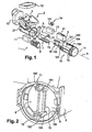
- FIG 1 On the figure 1 is shown in exploded view a device 1 for diffusion of volatile agents in a motor vehicle.
- volatile agents are generally fragrances impregnated in locks which, in the example of figure 1 , are two in number, respectively referenced 10 and 11, corresponding to different fragrances.
- the wicks 10, 11 are inserted into cartridges 8, 9 so as to be mounted in the diffusion device 1 in a manner that will be explained later.
- the diffusion device 1 comprises a housing 2 having an inlet 3 of ambient air coming from a fan 13 and intended to penetrate into a diffusion chamber 6 in which the cartridges 8, 9 of volatile agents are arranged.
- the diffusion chamber 6 has a substantially cylindrical shape of axis A, which constitutes the axis around which the main functions of the diffusion device 1 are organized.
- the ambient air takes care of one or the other of the fragrances.
- the air thus perfumed comes out of the diffusion chamber 6 by an air outlet 5 treated in the direction of a stopper 14 comprising radial distribution means around the axis A of the treated air coming from the outlet 5.
- said plug 14 is in the form of a hollow cylinder of axis A, said radial distribution means are then lateral holes 16 formed in the cylindrical wall of the plug 14.
- the plug 14 makes it possible to replace a generally unsightly opening and gate on the front with an element where the distribution holes are much more discreet and therefore less visible.
- the lateral outlet through the holes 16 redirects the treated air towards the aerators, between which the diffusion device 1 is installed. In this way, a homogeneous mixture of the air treated with the air coming from the aerators is quickly obtained, as well as a rapid diffusion and perception of the perfumed air throughout the vehicle.
- the cartridges 8, 9 are mounted on a cradle 15, which is introduced into a cylindrical insert 7 coaxial with the chamber 6 for sliding diffusion of beams 71, 72 of the insert 7 in rails 151, 152 of the cradle 15.
- an actuator 12 a stepping motor for example, makes it possible to drive in rotation around the axis A insert 7 and thus the cradle 15 and the cartridges 8, 9 since, by construction, the cradle 15 is rotatably connected to the insert 7.
- the cradle 15 remains mounted free in axial translation, along the axis A, on the insert 7.
- the actuator 12 By rotating the insert 7 about the axis A, the actuator 12 makes it possible to bring the cartridges into the following different functional positions.
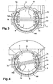
- the diffusion device 1 In the position of the figure 1 , which also corresponds to that of the figure 2 , the diffusion device 1 is out of operation (position called OFF) because, in this case, a wall 73 of the insert 7 totally obscures the inlet 3 of ambient air.
- the device 1 of diffusion of the figure 1 comprises means for automatic extraction of the cradle 15 out of the housing which will now be described in detail.
- these extraction means comprise an extraction drawer 18 of substantially cylindrical shape of axis A which, in diffusion mode of the device 1, is housed in the diffusion chamber 6 and contains the insert 7 with the cradle 15.
- the spool 18 is not coupled to the actuator 12 so that it undergoes no rotational movement, even when the actuator 12 is operating, in this case, only the insert 7 and the cradle 15 can turn around.
- axis A axis A.
- Said extraction means further comprise means for driving in axial translation, along the axis A, of the slide 18 out of the housing 2.
- the slide 18 also drives out the housing 2 the cradle 15 which is recalled that it is free in translation relative to the insert 7. It is then understood that, if the axial translation is performed over a distance at least equal to the length L of the cartridges 8, 9 taken parallel to the axis A, it is possible to completely clear one of the cartridges and thus replace it if it is worn.
- the drive means in axial translation of the slide 18 are selected of the so-called “push-pull” type, that is to say activated by an axial pressure action of the user on the drawer 18 extraction.
- these means are constituted by compression springs, not shown, arranged in grooves 22, 23 formed in the diffusion chamber 6 and cooperating with guides 182 of the slide 18.
- the initially compressed springs can then relax and apply to the drawer an axial translational movement to extract the drawer 18 and the cradle 15 out of the housing 2.
- locking means of the slide 18 in the housing 2 constituted by a cam 181 formed on the slide 18 cooperating with a bending spring 21 disposed on the housing.
- the bending spring 21 holds the slide 18 in the housing. If the user decides to change one of the cartridges 8, 9, he exerts pressure on the stopper 14 over a stroke of a few millimeters which has the effect of releasing the cam 181 of the spring 21 bending and thus to allow the springs compression to exercise their axial drive function of the slide 18 out of the housing 2.
- damping means of the translational movement of the slide 18 consisting for example of a rack 183 arranged longitudinally on the drawer 18 and a grease damper 19 comprising a pinion 191 cooperating with the rack 183.
- the user closes the drawer 18 by pushing it manually against the force of the compression springs until the bending spring 21 locks the cam 181.
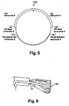
- the invention provides that such a replacement is only possible if the cradle 15 is rotated around the axis A by the actuator 12 in one or the other of two specific extraction angular positions each corresponding to the replacement of one of the cartridges 8 or 9, as shown in FIG. figure 5 .
- These extraction positions deviate about 10 ° from the ⁇ 90 ° ON Max positions.
- the total angular travel of the actuator is therefore about 200 °.
- the figure 4 shows more particularly the cartridge 8 in its angular extraction position.
- the drawer 18 can drive the cradle 15 out of the casing 2 by means of a hooking lug 184 arranged at the distal end of the drawer and cooperating with the cradle 15.
- stop means represented on the figures 2 and 3 , comprise a wall 185 formed on a peripheral sector of the drawer 18.
- a stop proper 74 is arranged on the insert 7 so that in all the different positions of the extraction angular positions, ON Maxi in the example of the figure 3 said abutment 74 is in contact with the wall 185 or at least at a distance less than the release stroke of the locking means. Again any axial pressure action on the slide 18 is neutralized because the wall 185 is blocked against the stop 74.
- the choice of the active cartridge, the intensity setting of the broadcast (ON positions), the stop of the broadcast (OFF position) and the request to replace a given cartridge can be done by the user. by means of an electronic control panel located on the dashboard of the vehicle.
- an opening detector of the drawer 18, not shown is placed on the housing 2 and provides the control panel with a signal to disable the device 1.
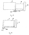
- the drawer 18 has on its board a housing 1800 in which is installed a spring 1801 said "constant force".
- This spring 1801 is a strip of metal wound on itself in a rest position. One end of the spring 1801 is fixed to the housing 2 and another end is fixed to the housing 1800.
- the drawer 18 is open. In this configuration, a cartridge is extractable from the drawer 18.
- the spring 1800 is meanwhile in a rest position in which it is completely wound on itself.
- the diffusion device 1 no longer requires any manual action of the user to open or close the drawer 18 to extract a cartridge 8, 9 no longer containing volatile agent.
- the actuator 12 controls both the rotational movement of the insert 7 and the translational movement of the slide 18.
- the diffusion device 1 comprises the housing 2, the insert 7, the cradle 15 the drawer 18 and the stopper 14.
- the slide 18 is connected to a first connecting rod 30, which is itself connected to a second connecting rod 32.
- the end of the second connecting rod 32 not connected to the first connecting rod 30 comprises a pinion 34 cooperating with a first wheel 36.
- This first toothed wheel 36 has a first toothed ring 360 acting with the pinion 34 and a second toothed ring 362 cooperating with a second toothed wheel 38 rotated by the actuator 12. In this way, when the actuator 12 is in operation, it rotates the second toothed wheel 38, which rotates the first toothed wheel 36.
- the rotation of the first toothed wheel 36 causes the second rod 32 to rotate, which causes the first link 30 to move.
- the drawer 18 is extracted in translation from the housing 2 under the action of the first connecting rod 30, the drawer 18 driving with it the cradle 15 as explained above.
- the assembly formed by the first connecting rod 30, the second connecting rod 32, the first toothed wheel 36 and the second gear wheel 38 is then the extraction means of the spool 18 of the housing 2 for the replacement of a cartridge 8, 9.
- This extraction means is controlled by the actuator 12.
- this second gear wheel 38 comprises a circular collar 380, of which two portions are provided with teeth.
- the second gear 38 comprises a first toothed portion 381 and a second toothed portion 382, the two portions 381, 382 being separated from one another.
- the second toothed wheel 38 rotates about the axis A, it rotates the first toothed wheel 36 via either the first toothed portion 381 or the second toothed portion 382.
- the collar 380 is toothless and can not mechanically cooperate with the first toothed wheel 36.
- the broadcasting device is represented in figure 8 according to a sectional view as seen above, the actuator 12 drives the second gear wheel 38 when a user controls the broadcasting device via a control interface no shown and placed at the dashboard of the vehicle.
- This second gear cooperates with the first toothed wheel 36 to open or close the diffusion device 1, that is to say extract or insert the drawer 18 of the housing 2.
- the translational movement of the slide 18 is ensured by the first 30 and the second 32 connecting rods, which are set in motion by the first toothed wheel 36 via the pinion 34.
- the insert 7 comprises in this embodiment a toothed wheel 76 cooperating with a rack 40.
- the latter 40 is in interaction with a cam path 384 formed on the second gear wheel 38.
- the mechanism for pivoting the insert 7 will be explained now.
- first toothed wheel 36 and the second toothed wheel 38 are shown.
- the latter 38 comprises a radial surface 383 on which a cam path 384 is formed. Consisting of a first 385a and a second 385b dead races and a race 386 for the pivoting of the insert 7, this cam path 384 cooperates with a pointer 400 to rotate the rack 40, the pointer 400 being formed on the rack 40.
- "Stroke for the pivoting of the insert” means the portion of cam path 384 in which the pointer 400 moves and rotates the rack 40.
- the toothed wheel 76 formed on the insert 7 cooperates with the rack 40 to rotate the insert 7.
- the second gear wheel 38 provided with the cam path 384 cooperates with the pointer 400 when the drawer 18 is inside the housing 2.
- the pointer 400 is located in the first dead race 385a.
- dead stroke is meant a portion of the cam path 384 in which the pointer 400 does not move, i.e., the rack 40 does not rotate.
- each dead stroke 385 corresponds to a circular path of axis A.
- the second gear 38 is in a position in which the pointer 400 is in the race 386 for the pivoting of the insert 7. This position is obtained by rotating the second gear 38 in the counter-clockwise direction. an initial position represented in figure 9 .
- the displacement of the pointer 400 involves the rotation of the rack 40 and the toothed wheel 76 and thus the rotation of the insert 7 so as to change the volatile agent to be diffused inside the cabin of the vehicle, to diffuse more or less volatile agent (diffusion intensity control), or ensure diffusion (cycling).
- the figure 12 represents a position of the second gear 38 in which the pointer 400 is in the second dead stroke 385b. If the actuator continues to drive the second gearwheel 38 counterclockwise, the pointer 400 will no longer move.
- the cam path 384 is positioned on the radial surface of the second gear 38 so as to cause a rotational movement of the insert 7 when the first toothed wheel 36 is not rotated by the second wheel 38. indeed, as in the first embodiment, the extraction and insertion of the slide 18 into the casing 2 are distinct and non-simultaneous steps of the step of rotation of the insert 7 for a change of diffusion of the volatile agent.
- the actuator 12 rotates the second gear 38 in a clockwise or counterclockwise direction. Accordingly, a return to the diffusion of the initial volatile agent is possible by a simple rotation of the actuator 12 in the clockwise direction.
- This embodiment has the following advantages.
- the springs to extract the drawer 18 are removed which ensures a robust system. Indeed, a spring can lose its strength as and when it is used.
- the diffusion device is easier to assemble, the mounting of the springs always being delicate when in the state of compression.
- Such an embodiment is economical because only one motor is required for all operations.
- the locking means and the damping means are no longer required since the translational movement of the slide 18 is integrally controlled by the actuator 12 and is no longer initiated by an action. axial pressure.
Landscapes
- Health & Medical Sciences (AREA)
- Veterinary Medicine (AREA)
- Life Sciences & Earth Sciences (AREA)
- Animal Behavior & Ethology (AREA)
- General Health & Medical Sciences (AREA)
- Public Health (AREA)
- Epidemiology (AREA)
- Engineering & Computer Science (AREA)
- Mechanical Engineering (AREA)
- Disinfection, Sterilisation Or Deodorisation Of Air (AREA)
- Air-Conditioning For Vehicles (AREA)
- Filtering Of Dispersed Particles In Gases (AREA)
- Catching Or Destruction (AREA)
- Fertilizers (AREA)
Claims (15)
- Einrichtung (1) zur Diffusion von mindestens einem flüchtigen Mittel in einem Kraftfahrzeug, umfassend ein Gehäuse (2), das einen Raumlufteintritt (3), einen Austritt (5) der behandelten Luft und eine Diffusionskammer (6) umfasst, die imstande ist, einen Einsatz (7) aufzunehmen, mindestens eine Kartusche (8, 9) mit einem flüchtigen Mittel, wobei der Einsatz (7) einen Tragkorb (15) umfasst, der die Kartusche (8, 9) trägt, wobei der Tragkorb frei axial verschiebbar auf dem Einsatz (7) befestigt ist, wobei die Einrichtung (1) Mittel zur Entnahme des Tragkorbs (15) aus dem Gehäuse (2) durch Parallelverschiebung zu einer Achse A umfasst, dadurch gekennzeichnet, dass die Einrichtung ferner ein Stellglied (12) umfasst, das den Einsatz (7) rund um die Drehachse A in Drehung versetzt, und dadurch, dass der Tragkorb (15) mit dem Einsatz (7) drehverbunden ist.
- Diffusionseinrichtung nach Anspruch 1, wobei die Entnahmemittel einen Entnahmeschieber (18), der in der Diffusionskammer (6) untergebracht ist und den Einsatz (7) enthält, und Mittel umfassen, um den Schieber (18) axial aus dem Gehäuse (2) zu schieben, wobei der Entnahmeschieber (18) imstande ist, den Tragkorb (15) unter Einwirkung der Mittel zur axialen Verschiebung aus dem Gehäuse (2) hinauszubewegen.
- Diffusionseinrichtung nach Anspruch 2, wobei die Mittel zur Verschiebung bei jedweder Winkelposition des Tragkorbs rund um die Achse A blockiert werden, die sich von einer gegebenen Entnahmewinkelposition unterscheidet.
- Diffusionseinrichtung nach Anspruch 3, wobei der Tragkorb (15) mithilfe des Stellglieds (12) in die Entnahmewinkelposition gebracht wird.
- Diffusionseinrichtung nach einem der Ansprüche 2 bis 4, wobei die Mittel zur axialen Verschiebung durch eine axiale Druckwirkung auf den Entnahmeschieber (18) aktiviert werden.
- Diffusionseinrichtung nach Anspruch 5, wobei die Mittel zur axialen Verschiebung mindestens eine Feder umfassen, die imstande ist, den Schieber (18) axial zu verschieben.
- Diffusionseinrichtung nach einem der Ansprüche 5 oder 6, umfassend Mittel zur Verriegelung (181, 21) des Entnahmeschiebers (18) im Gehäuse (2), wobei die Verriegelungsmittel imstande sind, unter der axialen Druckwirkung freigegeben zu werden.
- Diffusionseinrichtung nach Anspruch 7, wobei die Verriegelungsmittel einen Nocken (181) umfassen, der auf dem Schieber (18) angebracht ist und mit einer Biegefeder (21) zusammenwirkt, die auf dem Gehäuse (2) angeordnet ist.
- Diffusionseinrichtung nach einem der Ansprüche 3 bis 8, wobei der Entnahmeschieber (18) und der Einsatz (7) Anschlagmittel (185, 153, 154; 74) umfassen, die zum Blockieren der Freigabe der Verriegelungsmittel (181, 21) unter der axialen Druckwirkung bestimmt sind, wenn sich der Tragkorb (15) in einer Winkelposition befindet, die sich von der Entnahmewinkelposition unterscheidet.
- Diffusionseinrichtung nach einem der Ansprüche 2 bis 9, umfassend Mittel (183, 19) )zur Dämpfung der axialen Verschiebungsbewegung des Schiebers (18).
- Diffusionseinrichtung nach einem der Ansprüche 1 bis 10, wobei die Diffusionskammer (6) einen Sektor (S) mit einem größeren Durchmesser aufweist, der dazu bestimmt ist, die radiale Kompression der Dichtungsmittel (81) der Kartusche (8) in Entnahmeposition zu begrenzen.
- Einrichtung nach einem der Ansprüche 2 bis 11, umfassend einen Detektor der Öffnung des Schiebers, der imstande ist, ein Signal der Außerbetriebsetzung der Einrichtung (1) abzugeben, wenn sich der Schieber (18) außerhalb des Gehäuses (2) befindet.
- Einrichtung nach einem der Ansprüche 2 bis 12, wobei der Schieber (18) mit einem Deckel (14) ausgestattet ist, der Mittel (16) zur radialen Verteilung der behandelten Luft umfasst.
- Einrichtung nach einem der Ansprüche 2 bis 4, wobei das Mittel zur Verschiebung vom Stellglied (12) gesteuert wird.
- Diffusionseinrichtung nach Anspruch 14, wobei das Mittel zur Verschiebung mindestens zwei Zahnräder (36, 38) und mindestens zwei Kolbenstangen (30, 32) umfasst.
Applications Claiming Priority (1)
| Application Number | Priority Date | Filing Date | Title |
|---|---|---|---|
| FR0704768A FR2918318B1 (fr) | 2007-07-02 | 2007-07-02 | Dispositif de diffusion d'agent volatil muni d'un moyen d'extraction de cartouche |
Publications (2)
| Publication Number | Publication Date |
|---|---|
| EP2025544A1 EP2025544A1 (de) | 2009-02-18 |
| EP2025544B1 true EP2025544B1 (de) | 2010-02-24 |
Family
ID=39027092
Family Applications (1)
| Application Number | Title | Priority Date | Filing Date |
|---|---|---|---|
| EP08159493A Not-in-force EP2025544B1 (de) | 2007-07-02 | 2008-07-02 | Diffusionsvorrichtung für flüchtige Wirkstoffe, ausgestattet mit einem Mittel zum Entfernen von Patronen |
Country Status (7)
| Country | Link |
|---|---|
| US (1) | US8043570B2 (de) |
| EP (1) | EP2025544B1 (de) |
| KR (1) | KR101503529B1 (de) |
| AT (1) | ATE458634T1 (de) |
| DE (1) | DE602008000698D1 (de) |
| ES (1) | ES2340107T3 (de) |
| FR (1) | FR2918318B1 (de) |
Families Citing this family (13)
| Publication number | Priority date | Publication date | Assignee | Title |
|---|---|---|---|---|
| CN102245413B (zh) * | 2008-10-14 | 2014-03-12 | 汉拿伟世通空调有限公司 | 车辆空调装置的空气清新剂发生器 |
| KR101495804B1 (ko) * | 2009-02-17 | 2015-02-25 | 한라비스테온공조 주식회사 | 차량용 공조장치의 방향제 발생장치 |
| KR101406962B1 (ko) * | 2011-05-17 | 2014-06-13 | 한라비스테온공조 주식회사 | 차량용 방향 장치 |
| FR3026305B1 (fr) * | 2014-09-30 | 2017-11-24 | Valeo Systemes Thermiques | Dispositif de diffusion et cartouche pour ledit dispositif |
| FR3026306B1 (fr) * | 2014-09-30 | 2016-10-21 | Valeo Systemes Thermiques | Systeme de verrouillage de cartouche amovible dans un boitier |
| GB2542439A (en) * | 2015-09-15 | 2017-03-22 | Tata Motors European Technical Ct Plc | Scent cartridge housing and scent cartridge |
| JP6394655B2 (ja) | 2015-11-18 | 2018-09-26 | ソニー株式会社 | 回転切替装置 |
| FR3063681A1 (fr) * | 2017-03-08 | 2018-09-14 | Valeo Systemes Thermiques | Dispositif d'immobilisation d'une cartouche dans un boitier, boitier comprenant ledit dispositif et ensemble dudit boitier et de ladite cartouche |
| GB2560571A (en) * | 2017-03-16 | 2018-09-19 | Jaguar Land Rover Ltd | Automotive fragrance system |
| DE102020201256A1 (de) | 2020-02-03 | 2021-08-05 | Mahle International Gmbh | Beduftungsvorrichtung |
| WO2021245174A1 (en) * | 2020-06-02 | 2021-12-09 | Revoltab Ag | Air enhancing device |
| FR3144759B1 (fr) * | 2023-01-09 | 2024-11-22 | Psa Automobiles Sa | diffuseur de fragrance |
| GB2635533A (en) * | 2023-11-15 | 2025-05-21 | Jaguar Land Rover Ltd | Fragrance delivery unit |
Family Cites Families (4)
| Publication number | Priority date | Publication date | Assignee | Title |
|---|---|---|---|---|
| FR2815294B1 (fr) * | 2000-10-17 | 2003-07-18 | Valeo Climatisation | Dispositif de chauffage et de climatisation comportant des moyens d'odorisation de l'habitacle d' un vehicule |
| US7160515B2 (en) * | 2000-12-05 | 2007-01-09 | The Procter & Gamble Company | Volatile material-containing article |
| FR2865968B1 (fr) * | 2004-02-06 | 2008-04-11 | Bourbon Automobile Sa | Aerateur, notamment pour vehicule automobile |
| DE202004010015U1 (de) | 2004-06-25 | 2004-10-28 | Trw Automotive Electronics & Components Gmbh & Co.Kg | Luftverbesserungsvorrichtung zur Verwendung in Kraftfahrzeugen und Kartusche für die Luftverbesserungsvorrichtung |
-
2007
- 2007-07-02 FR FR0704768A patent/FR2918318B1/fr not_active Expired - Fee Related
-
2008
- 2008-07-01 US US12/165,864 patent/US8043570B2/en not_active Expired - Fee Related
- 2008-07-01 KR KR1020080063384A patent/KR101503529B1/ko not_active Expired - Fee Related
- 2008-07-02 EP EP08159493A patent/EP2025544B1/de not_active Not-in-force
- 2008-07-02 ES ES08159493T patent/ES2340107T3/es active Active
- 2008-07-02 DE DE602008000698T patent/DE602008000698D1/de active Active
- 2008-07-02 AT AT08159493T patent/ATE458634T1/de not_active IP Right Cessation
Also Published As
| Publication number | Publication date |
|---|---|
| US8043570B2 (en) | 2011-10-25 |
| FR2918318B1 (fr) | 2009-10-23 |
| KR20090004643A (ko) | 2009-01-12 |
| ES2340107T3 (es) | 2010-05-28 |
| DE602008000698D1 (de) | 2010-04-08 |
| ATE458634T1 (de) | 2010-03-15 |
| US20090072046A1 (en) | 2009-03-19 |
| KR101503529B1 (ko) | 2015-03-17 |
| EP2025544A1 (de) | 2009-02-18 |
| FR2918318A1 (fr) | 2009-01-09 |
Similar Documents
| Publication | Publication Date | Title |
|---|---|---|
| EP2025544B1 (de) | Diffusionsvorrichtung für flüchtige Wirkstoffe, ausgestattet mit einem Mittel zum Entfernen von Patronen | |
| EP1648737B1 (de) | Rückblickvorrichtung für ein kraftfahrzeug | |
| FR2720038A1 (fr) | Siège pour véhicule. | |
| EP2769862B1 (de) | Perfümzerstäubungsgerät in dem Innenraum eines Fahrzeugs, wie ein Kraftfahrzeug | |
| FR2702563A1 (fr) | Dispositif pour le prélèvement d'échantillons de sols. | |
| FR3057532A1 (fr) | Volant pour vehicule automobile autonome. | |
| FR2833531A1 (fr) | Dispositif d'odorisation a intensite reglable, notamment pour un vehicule automobile | |
| EP3265332B1 (de) | System zur immobilisierung einer auswechselbaren kassette in einem gehäuse | |
| FR2964917A1 (fr) | Elcairage d'ambiance integre a des systemes de toit ouvrant ou d'occultation. | |
| FR2613777A1 (fr) | Demarreur pour moteur de vehicule | |
| WO2020239320A1 (fr) | Dispositif de blocage de boite de vitesses | |
| EP0611690A1 (de) | Bei Stoss einfahrbare Lenksäuleeinrichtung | |
| EP2522547B1 (de) | Kabelgeführte Leuchtweitenregelungseinrichtung für Scheinwerfer eines Kraftfahrzeugs | |
| EP4133191B1 (de) | Scharnier zwischen zwei wänden einer flugzeugantriebseinheit | |
| EP1491392A1 (de) | Stufenlos Positionseinstellvorrichtung | |
| FR2883231A1 (fr) | Garniture d'articulation pour sieges de vehicule automobile et comprenant un rond | |
| FR2800021A1 (fr) | Siege de vehicule comportant un dossier basculable vers l'avant avec une commande a rattrapage de jeux | |
| FR2761654A1 (fr) | Dispositif de commande a lien souple et a rattrapage de jeu | |
| FR2912960A1 (fr) | Aerateur d'un systeme de ventilation d'un vehicule automobile et planche de bord de vehicule ainsi equipee. | |
| FR2868017A1 (fr) | Dispositif diffuseur de parfum ou analogue, pour habitacle de vehicule automobile | |
| FR3163092A1 (fr) | Dispositif d’actionnement d’une porte de véhicule automobile | |
| FR2885333A1 (fr) | Pare-soleil comportant des moyens de justification et de controle d'un temps de stationnement pour vehicule automobile | |
| FR2928298A1 (fr) | Dispositif de pivot de suspension de roue a voie reglable | |
| FR3165859A1 (fr) | Dispositif de fixation d’une batterie sur un cadre, et véhicule électrique comportant un tel dispositif | |
| FR2913715A1 (fr) | Systeme d'enroulement d'un rideau de composant a rideau enroulable de vehicule automobile,comprenant un dispositif de blocage desactivable lors du montage |
Legal Events
| Date | Code | Title | Description |
|---|---|---|---|
| PUAI | Public reference made under article 153(3) epc to a published international application that has entered the european phase |
Free format text: ORIGINAL CODE: 0009012 |
|
| AK | Designated contracting states |
Kind code of ref document: A1 Designated state(s): AT BE BG CH CY CZ DE DK EE ES FI FR GB GR HR HU IE IS IT LI LT LU LV MC MT NL NO PL PT RO SE SI SK TR |
|
| AX | Request for extension of the european patent |
Extension state: AL BA MK RS |
|
| 17P | Request for examination filed |
Effective date: 20090630 |
|
| GRAP | Despatch of communication of intention to grant a patent |
Free format text: ORIGINAL CODE: EPIDOSNIGR1 |
|
| AKX | Designation fees paid |
Designated state(s): AT BE BG CH CY CZ DE DK EE ES FI FR GB GR HR HU IE IS IT LI LT LU LV MC MT NL NO PL PT RO SE SI SK TR |
|
| GRAS | Grant fee paid |
Free format text: ORIGINAL CODE: EPIDOSNIGR3 |
|
| GRAA | (expected) grant |
Free format text: ORIGINAL CODE: 0009210 |
|
| AK | Designated contracting states |
Kind code of ref document: B1 Designated state(s): AT BE BG CH CY CZ DE DK EE ES FI FR GB GR HR HU IE IS IT LI LT LU LV MC MT NL NO PL PT RO SE SI SK TR |
|
| REG | Reference to a national code |
Ref country code: GB Ref legal event code: FG4D Free format text: NOT ENGLISH |
|
| REG | Reference to a national code |
Ref country code: CH Ref legal event code: EP |
|
| REG | Reference to a national code |
Ref country code: IE Ref legal event code: FG4D Free format text: LANGUAGE OF EP DOCUMENT: FRENCH |
|
| REF | Corresponds to: |
Ref document number: 602008000698 Country of ref document: DE Date of ref document: 20100408 Kind code of ref document: P |
|
| REG | Reference to a national code |
Ref country code: SE Ref legal event code: TRGR |
|
| REG | Reference to a national code |
Ref country code: ES Ref legal event code: FG2A Ref document number: 2340107 Country of ref document: ES Kind code of ref document: T3 |
|
| REG | Reference to a national code |
Ref country code: NL Ref legal event code: VDEP Effective date: 20100224 |
|
| LTIE | Lt: invalidation of european patent or patent extension |
Effective date: 20100224 |
|
| PG25 | Lapsed in a contracting state [announced via postgrant information from national office to epo] |
Ref country code: LT Free format text: LAPSE BECAUSE OF FAILURE TO SUBMIT A TRANSLATION OF THE DESCRIPTION OR TO PAY THE FEE WITHIN THE PRESCRIBED TIME-LIMIT Effective date: 20100224 Ref country code: HR Free format text: LAPSE BECAUSE OF FAILURE TO SUBMIT A TRANSLATION OF THE DESCRIPTION OR TO PAY THE FEE WITHIN THE PRESCRIBED TIME-LIMIT Effective date: 20100224 Ref country code: IS Free format text: LAPSE BECAUSE OF FAILURE TO SUBMIT A TRANSLATION OF THE DESCRIPTION OR TO PAY THE FEE WITHIN THE PRESCRIBED TIME-LIMIT Effective date: 20100624 Ref country code: NO Free format text: LAPSE BECAUSE OF FAILURE TO SUBMIT A TRANSLATION OF THE DESCRIPTION OR TO PAY THE FEE WITHIN THE PRESCRIBED TIME-LIMIT Effective date: 20100524 |
|
| PG25 | Lapsed in a contracting state [announced via postgrant information from national office to epo] |
Ref country code: SI Free format text: LAPSE BECAUSE OF FAILURE TO SUBMIT A TRANSLATION OF THE DESCRIPTION OR TO PAY THE FEE WITHIN THE PRESCRIBED TIME-LIMIT Effective date: 20100224 Ref country code: AT Free format text: LAPSE BECAUSE OF FAILURE TO SUBMIT A TRANSLATION OF THE DESCRIPTION OR TO PAY THE FEE WITHIN THE PRESCRIBED TIME-LIMIT Effective date: 20100224 Ref country code: FI Free format text: LAPSE BECAUSE OF FAILURE TO SUBMIT A TRANSLATION OF THE DESCRIPTION OR TO PAY THE FEE WITHIN THE PRESCRIBED TIME-LIMIT Effective date: 20100224 Ref country code: LV Free format text: LAPSE BECAUSE OF FAILURE TO SUBMIT A TRANSLATION OF THE DESCRIPTION OR TO PAY THE FEE WITHIN THE PRESCRIBED TIME-LIMIT Effective date: 20100224 Ref country code: PL Free format text: LAPSE BECAUSE OF FAILURE TO SUBMIT A TRANSLATION OF THE DESCRIPTION OR TO PAY THE FEE WITHIN THE PRESCRIBED TIME-LIMIT Effective date: 20100224 |
|
| REG | Reference to a national code |
Ref country code: IE Ref legal event code: FD4D |
|
| PG25 | Lapsed in a contracting state [announced via postgrant information from national office to epo] |
Ref country code: CY Free format text: LAPSE BECAUSE OF FAILURE TO SUBMIT A TRANSLATION OF THE DESCRIPTION OR TO PAY THE FEE WITHIN THE PRESCRIBED TIME-LIMIT Effective date: 20100224 Ref country code: IE Free format text: LAPSE BECAUSE OF FAILURE TO SUBMIT A TRANSLATION OF THE DESCRIPTION OR TO PAY THE FEE WITHIN THE PRESCRIBED TIME-LIMIT Effective date: 20100224 Ref country code: RO Free format text: LAPSE BECAUSE OF FAILURE TO SUBMIT A TRANSLATION OF THE DESCRIPTION OR TO PAY THE FEE WITHIN THE PRESCRIBED TIME-LIMIT Effective date: 20100224 Ref country code: NL Free format text: LAPSE BECAUSE OF FAILURE TO SUBMIT A TRANSLATION OF THE DESCRIPTION OR TO PAY THE FEE WITHIN THE PRESCRIBED TIME-LIMIT Effective date: 20100224 Ref country code: EE Free format text: LAPSE BECAUSE OF FAILURE TO SUBMIT A TRANSLATION OF THE DESCRIPTION OR TO PAY THE FEE WITHIN THE PRESCRIBED TIME-LIMIT Effective date: 20100224 Ref country code: GR Free format text: LAPSE BECAUSE OF FAILURE TO SUBMIT A TRANSLATION OF THE DESCRIPTION OR TO PAY THE FEE WITHIN THE PRESCRIBED TIME-LIMIT Effective date: 20100525 |
|
| PG25 | Lapsed in a contracting state [announced via postgrant information from national office to epo] |
Ref country code: SK Free format text: LAPSE BECAUSE OF FAILURE TO SUBMIT A TRANSLATION OF THE DESCRIPTION OR TO PAY THE FEE WITHIN THE PRESCRIBED TIME-LIMIT Effective date: 20100224 Ref country code: BG Free format text: LAPSE BECAUSE OF FAILURE TO SUBMIT A TRANSLATION OF THE DESCRIPTION OR TO PAY THE FEE WITHIN THE PRESCRIBED TIME-LIMIT Effective date: 20100524 |
|
| PLBE | No opposition filed within time limit |
Free format text: ORIGINAL CODE: 0009261 |
|
| STAA | Information on the status of an ep patent application or granted ep patent |
Free format text: STATUS: NO OPPOSITION FILED WITHIN TIME LIMIT |
|
| BERE | Be: lapsed |
Owner name: VALEO SYSTEMES THERMIQUES Effective date: 20100731 |
|
| PG25 | Lapsed in a contracting state [announced via postgrant information from national office to epo] |
Ref country code: DK Free format text: LAPSE BECAUSE OF FAILURE TO SUBMIT A TRANSLATION OF THE DESCRIPTION OR TO PAY THE FEE WITHIN THE PRESCRIBED TIME-LIMIT Effective date: 20100224 |
|
| 26N | No opposition filed |
Effective date: 20101125 |
|
| PG25 | Lapsed in a contracting state [announced via postgrant information from national office to epo] |
Ref country code: MC Free format text: LAPSE BECAUSE OF NON-PAYMENT OF DUE FEES Effective date: 20100731 |
|
| PG25 | Lapsed in a contracting state [announced via postgrant information from national office to epo] |
Ref country code: BE Free format text: LAPSE BECAUSE OF NON-PAYMENT OF DUE FEES Effective date: 20100731 |
|
| PG25 | Lapsed in a contracting state [announced via postgrant information from national office to epo] |
Ref country code: MT Free format text: LAPSE BECAUSE OF FAILURE TO SUBMIT A TRANSLATION OF THE DESCRIPTION OR TO PAY THE FEE WITHIN THE PRESCRIBED TIME-LIMIT Effective date: 20100224 |
|
| PG25 | Lapsed in a contracting state [announced via postgrant information from national office to epo] |
Ref country code: HU Free format text: LAPSE BECAUSE OF FAILURE TO SUBMIT A TRANSLATION OF THE DESCRIPTION OR TO PAY THE FEE WITHIN THE PRESCRIBED TIME-LIMIT Effective date: 20100825 Ref country code: LU Free format text: LAPSE BECAUSE OF NON-PAYMENT OF DUE FEES Effective date: 20100702 Ref country code: PT Free format text: LAPSE BECAUSE OF FAILURE TO SUBMIT A TRANSLATION OF THE DESCRIPTION OR TO PAY THE FEE WITHIN THE PRESCRIBED TIME-LIMIT Effective date: 20100724 |
|
| PG25 | Lapsed in a contracting state [announced via postgrant information from national office to epo] |
Ref country code: TR Free format text: LAPSE BECAUSE OF FAILURE TO SUBMIT A TRANSLATION OF THE DESCRIPTION OR TO PAY THE FEE WITHIN THE PRESCRIBED TIME-LIMIT Effective date: 20100224 |
|
| REG | Reference to a national code |
Ref country code: CH Ref legal event code: PL |
|
| GBPC | Gb: european patent ceased through non-payment of renewal fee |
Effective date: 20120702 |
|
| PG25 | Lapsed in a contracting state [announced via postgrant information from national office to epo] |
Ref country code: GB Free format text: LAPSE BECAUSE OF NON-PAYMENT OF DUE FEES Effective date: 20120702 Ref country code: LI Free format text: LAPSE BECAUSE OF NON-PAYMENT OF DUE FEES Effective date: 20120731 Ref country code: CH Free format text: LAPSE BECAUSE OF NON-PAYMENT OF DUE FEES Effective date: 20120731 |
|
| REG | Reference to a national code |
Ref country code: FR Ref legal event code: PLFP Year of fee payment: 9 |
|
| REG | Reference to a national code |
Ref country code: FR Ref legal event code: PLFP Year of fee payment: 10 |
|
| REG | Reference to a national code |
Ref country code: FR Ref legal event code: PLFP Year of fee payment: 11 |
|
| PGFP | Annual fee paid to national office [announced via postgrant information from national office to epo] |
Ref country code: CZ Payment date: 20190620 Year of fee payment: 12 |
|
| PGFP | Annual fee paid to national office [announced via postgrant information from national office to epo] |
Ref country code: FR Payment date: 20190731 Year of fee payment: 12 Ref country code: IT Payment date: 20190718 Year of fee payment: 12 Ref country code: DE Payment date: 20190711 Year of fee payment: 12 Ref country code: SE Payment date: 20190722 Year of fee payment: 12 Ref country code: ES Payment date: 20190809 Year of fee payment: 12 |
|
| PG25 | Lapsed in a contracting state [announced via postgrant information from national office to epo] |
Ref country code: CZ Free format text: LAPSE BECAUSE OF NON-PAYMENT OF DUE FEES Effective date: 20200702 |
|
| REG | Reference to a national code |
Ref country code: DE Ref legal event code: R119 Ref document number: 602008000698 Country of ref document: DE |
|
| REG | Reference to a national code |
Ref country code: SE Ref legal event code: EUG |
|
| PG25 | Lapsed in a contracting state [announced via postgrant information from national office to epo] |
Ref country code: FR Free format text: LAPSE BECAUSE OF NON-PAYMENT OF DUE FEES Effective date: 20200731 |
|
| PG25 | Lapsed in a contracting state [announced via postgrant information from national office to epo] |
Ref country code: DE Free format text: LAPSE BECAUSE OF NON-PAYMENT OF DUE FEES Effective date: 20210202 Ref country code: SE Free format text: LAPSE BECAUSE OF NON-PAYMENT OF DUE FEES Effective date: 20200703 |
|
| PG25 | Lapsed in a contracting state [announced via postgrant information from national office to epo] |
Ref country code: IT Free format text: LAPSE BECAUSE OF NON-PAYMENT OF DUE FEES Effective date: 20200702 |
|
| REG | Reference to a national code |
Ref country code: ES Ref legal event code: FD2A Effective date: 20211228 |
|
| PG25 | Lapsed in a contracting state [announced via postgrant information from national office to epo] |
Ref country code: ES Free format text: LAPSE BECAUSE OF NON-PAYMENT OF DUE FEES Effective date: 20200703 |