EP2022734A2 - Convoyeur linéaire de vibrations - Google Patents
Convoyeur linéaire de vibrations Download PDFInfo
- Publication number
- EP2022734A2 EP2022734A2 EP08009881A EP08009881A EP2022734A2 EP 2022734 A2 EP2022734 A2 EP 2022734A2 EP 08009881 A EP08009881 A EP 08009881A EP 08009881 A EP08009881 A EP 08009881A EP 2022734 A2 EP2022734 A2 EP 2022734A2
- Authority
- EP
- European Patent Office
- Prior art keywords
- linear conveyor
- drive unit
- conveyor according
- vibratory linear
- counterweight
- Prior art date
- Legal status (The legal status is an assumption and is not a legal conclusion. Google has not performed a legal analysis and makes no representation as to the accuracy of the status listed.)
- Granted
Links
- 230000003014 reinforcing effect Effects 0.000 claims abstract 3
- 239000007788 liquid Substances 0.000 claims description 18
- 239000012528 membrane Substances 0.000 claims description 10
- 230000010355 oscillation Effects 0.000 abstract description 12
- 230000033001 locomotion Effects 0.000 description 25
- 230000003321 amplification Effects 0.000 description 6
- 238000003199 nucleic acid amplification method Methods 0.000 description 6
- 239000000463 material Substances 0.000 description 5
- 230000008878 coupling Effects 0.000 description 4
- 238000010168 coupling process Methods 0.000 description 4
- 238000005859 coupling reaction Methods 0.000 description 4
- 239000012744 reinforcing agent Substances 0.000 description 3
- 238000004904 shortening Methods 0.000 description 3
- 238000005452 bending Methods 0.000 description 2
- 239000003795 chemical substances by application Substances 0.000 description 2
- 239000012530 fluid Substances 0.000 description 2
- 238000004804 winding Methods 0.000 description 2
- 230000004913 activation Effects 0.000 description 1
- 238000013459 approach Methods 0.000 description 1
- 230000005540 biological transmission Effects 0.000 description 1
- 125000004122 cyclic group Chemical group 0.000 description 1
- 230000007423 decrease Effects 0.000 description 1
- 230000001419 dependent effect Effects 0.000 description 1
- 238000010586 diagram Methods 0.000 description 1
- 238000006073 displacement reaction Methods 0.000 description 1
- 230000002708 enhancing effect Effects 0.000 description 1
- 238000005457 optimization Methods 0.000 description 1
- 239000004033 plastic Substances 0.000 description 1
- 239000004810 polytetrafluoroethylene Substances 0.000 description 1
- 229920001343 polytetrafluoroethylene Polymers 0.000 description 1
- 230000002787 reinforcement Effects 0.000 description 1
- 230000002040 relaxant effect Effects 0.000 description 1
- 230000001360 synchronised effect Effects 0.000 description 1
- 238000011144 upstream manufacturing Methods 0.000 description 1
Images


Classifications
-
- B—PERFORMING OPERATIONS; TRANSPORTING
- B65—CONVEYING; PACKING; STORING; HANDLING THIN OR FILAMENTARY MATERIAL
- B65G—TRANSPORT OR STORAGE DEVICES, e.g. CONVEYORS FOR LOADING OR TIPPING, SHOP CONVEYOR SYSTEMS OR PNEUMATIC TUBE CONVEYORS
- B65G27/00—Jigging conveyors
- B65G27/10—Applications of devices for generating or transmitting jigging movements
- B65G27/16—Applications of devices for generating or transmitting jigging movements of vibrators, i.e. devices for producing movements of high frequency and small amplitude
- B65G27/26—Applications of devices for generating or transmitting jigging movements of vibrators, i.e. devices for producing movements of high frequency and small amplitude with elastic coupling between vibrator and load carrier
-
- B—PERFORMING OPERATIONS; TRANSPORTING
- B65—CONVEYING; PACKING; STORING; HANDLING THIN OR FILAMENTARY MATERIAL
- B65G—TRANSPORT OR STORAGE DEVICES, e.g. CONVEYORS FOR LOADING OR TIPPING, SHOP CONVEYOR SYSTEMS OR PNEUMATIC TUBE CONVEYORS
- B65G27/00—Jigging conveyors
- B65G27/10—Applications of devices for generating or transmitting jigging movements
- B65G27/28—Applications of devices for generating or transmitting jigging movements with provision for dynamic balancing
- B65G27/30—Applications of devices for generating or transmitting jigging movements with provision for dynamic balancing by means of an oppositely-moving mass, e.g. a second conveyor
Definitions
- the invention relates to a vibratory linear conveyor comprising a useful mass and a counterweight, which are swingably movable via a drive unit in opposite directions, wherein the drive unit is preferably arranged in a receiving space below the payload.
- Such vibratory linear conveyors are used to promote small and smallest components, for example to an automatic assembly machine, where the components are either processed or installed.
- the principle of operation of such a vibratory linear conveyor is based on the fact that a counterweight and a payload, part of which is a conveyor rail, along which the components are moved, are brought into an opposite oscillating motion, so that there is a micro-movement of the components on the conveyor rail.
- the payload and the counterweight are in each case via corresponding spring elements, mainly leaf springs or leaf spring packets, with the bottom plate, via which the vibrating linear conveyor is connected to a third object, such as a mounting table, connected swinging.
- the drive unit is usually an electromagnet used, wherein usually the magnetic core is connected to the surrounding winding with the counterweight and the armature with the useful mass.
- the alternating voltage is applied to the winding, there is a magnetic field which changes as a function of the voltage frequency and acts on the armature, which is freely movable relative to the magnet core and thus not connected to it, which ultimately results in the opposite oscillating motion of the two masses.
- the operating principle is usually such that when the electromagnet is energized, ie when the coil is energized, the armature is pulled onto or into the magnet core via the built-up magnetic field.
- the Nutz- and the counterweight are virtually moved towards each other, the spring elements are bent accordingly.
- the reset takes place with de-energized electromagnet alone on the relaxing spring elements.
- the stroke of the electromagnet is limited, which sometimes a relatively low amplitude results, which in turn leads to a low average flow rate.
- the invention is therefore based on the problem to provide a vibratory linear conveyor, in which regardless of the type of drive unit used, a sufficient amplitude is ensured.
- a vibration linear conveyor of the type mentioned that the payload and the counterweight via a non-rigid connection, which is or includes a vibration amplifying means for the vibration generated by the drive unit connected.
- the useful mass and the counterweight are movably connected to each other, unlike in the prior art, where both are freely movable to each other.
- the non-rigid, movable mechanical ground connection forms or includes a vibration amplifying means, whereby an active amplification of the vibration or movement generated by the drive unit is possible.
- any movement component of the drive unit be it in one direction or the other, transmitted via a vibration amplification means to the two masses via the drive unit, wherein the movement of the the useful or the countermass arranged drive unit which exerts this for vibration generation on the vibration-enhancing mechanical mass connection, is increased via this vibration amplification, so that based on the obtained oscillation amplitude of the drive stroke significantly increased and the oscillation amplitude increases significantly, depending on the transmission ratio of the vibration amplifying agent, that is, the ratio in which the stroke generated by the drive unit stands for the resulting oscillation stroke.
- the drive unit may be a piezoelectric drive.
- a piezoelectric drive has an actuator made of a piezoelectric material. At this high frequency AC voltage is applied. With applied voltage, the piezoelectric actuator changes its geometry. Usually, with such materials, a defined elongation in the one and shortening in a direction perpendicular thereto over a first positive voltage edge and a corresponding movement in the opposite directions over the second negative voltage edge of the AC voltage can be achieved. After such materials are able to change their shape with very high frequency, it is advantageously possible with such an actuator to generate very high-frequency vibrations.
- the actuator is connected in such a way in the mechanical connection that it acts on the two masses.
- An alternative drive unit can be designed in the form of a pneumatically or hydraulically reversibly expandable bellows.
- a bellows is connected between useful and counterweight, it can be acted upon by a pneumatic or hydraulic working fluid. He also forms a mechanical connection element.
- the bellows can between two maximum states, namely a maximum inflated and a definable via the control unloaded state can be varied, with the change enters into a geometry change. If the bellows is increased, ie inflated, for example, it expands, depending on the embodiment, preferably defined in a direction perpendicular to the bending axis, via which the two masses move apart and thus the respective spring elements are bent away from one another.
- a restoring force is built up, ie, the spring elements also work here continuously against the expanding bellows. If this is relieved, then the spring elements can relax, the relaxation movement is always defined and limited by the bellows, after the spring elements always work during the relaxation against the bellows.
- Such a bellows can be reversibly loaded and unloaded sufficiently quickly via one or more upstream valve elements, so that sufficiently high vibration frequencies can be achieved here as well.
- a third alternative embodiment of a drive unit is that of an eccentric or at least one eccentrically arranged part driving drive motor.
- Such an eccentric drive motor has a drive shaft, on which, for example, one or two opposing positions, ie offset by 180 degrees cams as the drive axis eccentric or offset parts are arranged. It can also be more than two cams, then preferably distributed equidistantly be provided.
- Against the drive shaft and thus against the cam in turn work the spring elements. In the one maximum position, in which the cams are vertical and therefore do not attack the useful and countermass, the spring elements are in the relaxed position, the two masses are pressed by the spring elements against the drive shaft.
- the usable vibration enhancing agent may be different in nature. It may be a mechanical reinforcing agent, in which therefore the path translation is effected solely by the mechanical design of the reinforcing agent. However, it is also conceivable to use a hydraulically or pneumatically operated reinforcing agent.
- a mechanical vibration amplifying means may be realized in the form of at least one spring element connecting the useful mass and the counterweight.
- this spring element it is possible to increase the stroke of the drive unit and thereby amplify the vibration.
- This is particularly useful in the case of a piezoelectric drive, since the change in length of the piezoelectric element is relatively low and this longitudinal movement is increased via the coupled spring element and thus the stroke can be potentiated.
- this spring element can also be used in the design of the drive unit as a hydraulic or pneumatic bellows or as an eccentric or cam drive. Because it is then possible to design these drive units a little smaller, so that the stroke of the bellows can be reduced or even z. B. the cam lift can be made shorter.
- the respective drive unit operates directly against the spring element.
- D. h. The vibration of the drive unit is coupled directly into the spring element, where it is amplified accordingly.
- the spring element itself is preferably a curved leaf spring, which particularly suitably has a U-shape. This U-shape with two side legs, which are vertical in the mounting position, and a transverse leg that connects these two side legs is special expedient with regard to the linear movement of the masses, ie for the linear stroke.
- a further advantageous embodiment of the invention provides that the rigidity of the spring element, in particular of the leaf spring, varies over its length. This offers the possibility to be able to set a greater amplitude in certain spring ranges, d. h., The spring oscillates in this area a little further, which is useful for the reinforcement.
- the bent leaf spring may be narrower in the region of the spring leg facing away from the drive unit. D. h., The geometry of the spring changes to the spring leg, which is not directly or for example via an intermediate piece indirectly coupled to the drive unit. For example, the width of the spring leg in this area decreases to half the width of the other spring leg.
- the leaf spring is thus in two parts.
- a first, in turn, already substantially U-shaped spring member has a first thickness, for example of about 1.5 mm, while a second spring member which is connected to the one free, so not directly or indirectly acted upon by the drive unit spring leg, has a second thickness of, for example, 0.8 mm.
- a mechanical vibration amplifying means may also be realized in the form of a hinge, one of whose legs rotatably connected to the payload and the other leg is rotatably connected to the counterweight. About the leg length and the angle between the legs, which they take in the closest possible position to each other, a considerable translation can be achieved.
- the drive unit eg the piezoactuator, works against one of the two legs of the hinge.
- a hydraulically or pneumatically operated amplifying means can be realized in the form of two pistons connected in series, the diameter of the piston coupled to the useful mass being smaller than that of the piston coupled to the counterweight, or vice versa.
- the small piston shifts by e.g. 10 mm when the large piston is moved by 1 mm.
- the larger piston can be realized by means of a membrane which delimits a liquid reservoir and which can be moved indirectly or directly via the drive unit. Via the drive unit, the membrane is moved, whereupon the liquid, e.g. an oil is acted upon.
- the liquid reservoir has a smaller diameter portion into which the liquid is forced, the distance traveled being much longer than the membrane has been moved.
- the second piston is provided, which is moved over the moving liquid column and moves over the other mass. If the membrane is relieved, then the second piston can push back the liquid column again, it comes to the vibration, the oscillation is significantly increased over the quasi-hydraulically realized translation.
- Fig. 1 shows a vibratory linear conveyor 1 according to the invention, comprising a bottom plate 2, a counterweight 3 and a payload 4, of which only a part is shown. Not shown is to be arranged on the payload 4 conveyor rail, along which are conveyed to the vibrating linear conveyor 1 to be moved components.
- the counterweight 3 and the payload 4 are connected at both ends via spring elements 5, 6 with the bottom plate 2, via which spring elements 5, 6, the counterweight 3 and the payload 4 can swing against each other.
- the respective masses 3, 4 with the bottom plate 2 connecting spring elements 5, 6, which are leaf spring packets are - viewed in the longitudinal direction of the vibrating linear conveyor 1 - arranged offset by cross. That is, based on the illustration in Fig.
- a pocket 7 is milled, in which the drive means 8, in which it is in the illustrated embodiment according to Fig. 1 is a piezoelectric drive, is arranged.
- the piezoelectric drive 8 comprises a piezoelectric actuator 9, which is arranged in a suitable actuator housing 10, which is located on a mounting block 11 with the payload 4.
- the piezoelectric actuator 9 engages directly on the spring leg 13, when it controlled by a high-frequency drive voltage performs its defined change in length.
- the spring element 12 has a second spring leg 14, which is in two parts here. It includes a first leg portion 15 as part of the integral U-shaped leaf spring having a first thickness. With this a second leg portion 17 is connected via a fixed connection 16, which has a smaller thickness, and therefore has a different spring behavior. He is further deflected due to the smaller thickness with the same applied force. By way of this, a significant increase or increase in the oscillation width achievable via the piezoelectric drive 9 can be achieved.
- the leg portion 17 is arranged in a suitable holder 18, which in turn is connected to the counterweight 3 or is part of this.
- the piezoelectric drive 8 is driven with a high-frequency control voltage.
- the piezoelectric actuator 9 performs a voltage-dependent defined change in length.
- the piezoelectric actuator 9 When concerns of a control voltage half-wave lengthen the piezoelectric actuator 9, when the other half-wave concerns it shortens seen in its effective direction.
- the piezoelectric actuator thus operates directly against the spring element 12.
- the spring elements 5, 6 are pressed apart, they bend around the respective bending axis.
- the piezoelectric drive 8 has an adjusting element 29, by way of which the relative position of the piezoelectric actuator 9 relative to the U-shaped spring element 12 can be adjusted.
- an optimization of the piezoelectric actuator position relative to the spring element 12 can be carried out, as well as a possible pretensioning of the spring element 12 can be set via this.
- FIG. 2 Another inventive embodiment of a vibratory linear conveyor shows Fig. 2 ,
- the structure of the vibratory linear conveyor 1 shown there corresponds to that Fig. 1 , It is therefore also a bottom plate 2 is provided, via which the vibrating linear conveyor 1 is screwed to a machine frame or the like, as well as a counterweight 3 and a payload 4 are present. Both are in turn via spring elements 5, 6 against each other and arranged relative to the bottom plate 2 vibrationally movable on this.
- the drive unit provided here is an electric drive motor 19 with eccentrically arranged cams.
- the motor 19 has an output shaft 20, on which an eccentric component 21 with two projecting cams 22 is arranged.
- the drive motor 19 is in turn arranged on a connection block 11, which in turn is attached to the payload 4.
- a vibration amplifying element in the form of a U-shaped spring element 12, which is made of Fig. 1 equivalent. D. h., This is arranged with its spring element legs 13 on the connecting block 11 and thus on the payload 4, while the second spring element leg 14, which is also made in two parts, is connected via a connecting block 18 with the counterweight 3.
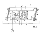
- FIG. 3 a further embodiment of a vibration linear conveyor according to the invention, whose structure corresponds to the embodiments described above, thus also here a bottom plate 2, a counterweight 3 and a payload 4 are provided, which are mounted on respective spring elements 5, 6.
- a reversibly expandable bellows 25 As drive unit 24 is here a reversibly expandable bellows 25, z. B. of plastic (eg., PTFE) is provided, which can be hydraulically or pneumatically between a maximum expanded position and a relieved form in which it is slightly smaller, can be made.
- a suitable hydraulic or pneumatic line 26 is provided, which is preceded by a corresponding valve member 27, which in turn communicates with a pump P.
- the expandable bellows is arranged on a suitable housing component 28, which in turn can be adjusted via an adjusting element 29 relative to the U-shaped spring element 12.
- the housing member 28 is in turn arranged on the connecting block 11 and thus firmly connected to the useful mass 4, on which connecting block 11 and the leg 13 of the U-shaped spring element 12 is arranged, which is again designed in two parts and with the second leg 14, respectively whose second leg portion 17 is arranged on the connecting block 18 of the counterweight 3.
- the inflatable bladder 25 can also be expanded and relieved at a high frequency, which involves a change in geometry.
- the valve element 27 is controlled accordingly via a suitable control line via a controller not shown in detail.
- the bellows 25 works directly against the spring element 12, so that this is moved to the right with expanded bellows 25, the spring element oscillation is transmitted to the counterweight 3 in reinforced form, both masses 3, 4 move apart, the spring elements 5, 6 are bent away from each other. If the bellows 25 is relieved so can the spring elements 5, 6 relax, the masses are moved back towards each other, the spring element 12 moves to the left. Its position or geometry is essentially wegbethered for the disassembly and return movement of the spring elements 5, 6 and thus the masses 3, 4. It is therefore Here, too, given a continuous mechanical flexible connection, part of which is the bellows.
- Fig. 4 shows a vibratory linear conveyor according to the invention, the structure of which corresponds to the embodiment described above, also here is a bottom plate 2, a counterweight 3 and a payload 4 are provided, which are mounted for swinging via corresponding spring elements 5, 6.
- drive unit 30 is also here, as with respect Fig. 1 described, a piezoelectric drive unit 31 is provided, which is arranged in the embodiment shown on the counterweight 3.
- a vibration amplifying means here is a hydraulic piston assembly 32 is provided, comprising a first hydraulic piston 33 which is associated with the counterweight 3, and in the second piston 34 which is connected to the payload 4 or acts on these.
- the hydraulic piston 33 comprises a liquid reservoir 35, which is filled with a liquid, for example a hydraulic fluid 36.
- the piezoelectric drive 31 acts on a flexible membrane 37, which closes off the hydraulic piston 33 to the side of the counterweight 3 out.
- the preferably circular diameter of the membrane 37 or of the liquid reservoir 35 in this region is significantly greater than in a tapering section 38, in which the liquid reservoir is bounded by a second membrane 39, likewise flexible.
- This liquid column 40 which is arranged in this narrowed portion 38, presses on the second piston 34, which in turn is coupled to the useful mass 4. If, in the example shown, the membrane 37 is pushed to the left, the volume of the wide region 41 of the liquid reservoir is reduced, liquid 36 is pressed into the tapered section 38, and the liquid column 40 is extended beyond which the second piston 34 is moved to the left.
- the two masses 3, 4 are pressed apart and also the spring elements 5, 6 moved away from each other.
- the piezoelectric actuator 31 shortens again, the spring elements 5, 6 can relax, the second piston 34 pushes the liquid column 40 back again, the membrane 37 is moved in the example shown to the right.
- Fig. 5 finally shows a fifth embodiment of a vibratory linear conveyor according to the invention, whose structure also corresponds to the embodiments described above.
- a vibration amplifying means here is a hinge 42 is used, consisting of two legs 43, 44 which are pivotally connected to each other via a first joint 45. The two ends of the legs 43, 44 are connected via respective hinges 46, 47 with the payload 4 and the counterweight 3.
- This rotary joint is the shape that the rotational movement of the legs 43, 44 is limited, that is, it is defined an angular position to which the angle can be pivoted toward each other, a further pivotal movement of the legs 43, 44 to each other is on the part of the joints 46th , 47 locked. It is therefore defined a minimum opening angle of the hinge 42 via the joints 46, 47.
- a piezoelectric drive 49 is also provided here, which is arranged in the example shown on the payload and acts directly on the Nutzmassen owned hinged leg 43.
- the hinge is moved or pivoted about the hinge 46 to the right.
- the hinge 47 pivoting of the leg 44 according to Fig. 4 to the right does not allow this, the counterweight 3 is inevitably moved to the right.
- the path that the axis of rotation of the joint 47 is moved to the right is significantly greater than the path that the axis of rotation of the joint 45 is shifted to the right.
- the length of the resulting Nutzmassenterrorism is therefore the result of the displacement of the hinge relative to the joint 46 and the angular change of the opening angle between the two legs 43, 44.
- the piezoelectric actuator 49 should attack as close to the joint 46, so that despite low Aktorhub the joint 45 as far as possible on the right and, as a result, the hinge 47 and with it the payload 3 of the hinge geometry is moved further.
Landscapes
- Engineering & Computer Science (AREA)
- Mechanical Engineering (AREA)
- Jigging Conveyors (AREA)
- Apparatuses For Generation Of Mechanical Vibrations (AREA)
Applications Claiming Priority (1)
| Application Number | Priority Date | Filing Date | Title |
|---|---|---|---|
| DE102007036491A DE102007036491B4 (de) | 2007-08-01 | 2007-08-01 | Vibrationslinearförderer |
Publications (3)
| Publication Number | Publication Date |
|---|---|
| EP2022734A2 true EP2022734A2 (fr) | 2009-02-11 |
| EP2022734A3 EP2022734A3 (fr) | 2009-08-26 |
| EP2022734B1 EP2022734B1 (fr) | 2013-10-02 |
Family
ID=39845136
Family Applications (1)
| Application Number | Title | Priority Date | Filing Date |
|---|---|---|---|
| EP08009881.7A Active EP2022734B1 (fr) | 2007-08-01 | 2008-05-30 | Convoyeur linéaire de vibrations |
Country Status (5)
| Country | Link |
|---|---|
| US (1) | US8051974B2 (fr) |
| EP (1) | EP2022734B1 (fr) |
| CA (1) | CA2636968C (fr) |
| DE (1) | DE102007036491B4 (fr) |
| DK (1) | DK2022734T3 (fr) |
Cited By (1)
| Publication number | Priority date | Publication date | Assignee | Title |
|---|---|---|---|---|
| CN103922085A (zh) * | 2014-03-27 | 2014-07-16 | 长治市中瑞精密轴承制造有限公司 | 轴承滚子电磁加料装置 |
Families Citing this family (4)
| Publication number | Priority date | Publication date | Assignee | Title |
|---|---|---|---|---|
| DE102009004990A1 (de) * | 2009-01-14 | 2010-07-22 | Feintool Intellectual Property Ag | Vibrationslinearförderer |
| WO2014197552A1 (fr) * | 2013-06-05 | 2014-12-11 | Intelligrated Headquarters Llc | Transporteur trieur ayant un actionnement piézoélectrique |
| CA3051120C (fr) | 2015-07-03 | 2021-11-23 | George D. Dumbaugh | Dispositif d'alimentation a tamis vibrant et procede d'utilisation |
| US11780679B2 (en) | 2019-04-05 | 2023-10-10 | Blue Sky Ventures (Ontario) Inc. | Vibratory conveyor for conveying items and related filling machine and methods |
Citations (1)
| Publication number | Priority date | Publication date | Assignee | Title |
|---|---|---|---|---|
| JPH0351210A (ja) | 1989-07-20 | 1991-03-05 | Toshiba Corp | 圧電駆動形搬送装置 |
Family Cites Families (18)
| Publication number | Priority date | Publication date | Assignee | Title |
|---|---|---|---|---|
| US3786912A (en) * | 1970-11-20 | 1974-01-22 | Automation Devices Inc | Linear vibratory feeder |
| US4341126A (en) * | 1977-02-25 | 1982-07-27 | Thomas Hubert E | Variable amplitude vibratory apparatus |
| US4378064A (en) * | 1980-09-22 | 1983-03-29 | Fmc Corporation | Three mass electromagnetic feeder |
| US4340469A (en) * | 1981-01-23 | 1982-07-20 | Spokane Crusher Mfg. Co. | Vibratory screen apparatus |
| JP2565547B2 (ja) * | 1988-07-04 | 1996-12-18 | 大和製衡株式会社 | 電磁振動物品搬送装置 |
| US5314056A (en) * | 1993-03-23 | 1994-05-24 | Key Technology, Inc. | High-speed vibratory alignment and singulation conveyor |
| US5664664A (en) * | 1994-12-28 | 1997-09-09 | U.S. Vibra, Inc. | Magnetic vibrator sub-assembly for vibratory feed devices |
| JP3096805B2 (ja) * | 1995-11-20 | 2000-10-10 | 株式会社セラテック | 圧電式搬送装置 |
| DE19609039A1 (de) * | 1996-03-08 | 1997-09-11 | Netter Gmbh | Resonanzschwingförderer |
| US5850906A (en) * | 1996-08-02 | 1998-12-22 | Fmc Corporation | Bi-directional, differential motion conveyor |
| US6415913B2 (en) | 1997-03-17 | 2002-07-09 | Fmc Technologies, Inc. | Excited base conveyor system |
| US6047811A (en) * | 1997-08-21 | 2000-04-11 | David R. Zittel | Method and vibratory conveyor |
| TW422807B (en) * | 1998-02-23 | 2001-02-21 | Shinko Electric Co Ltd | Vibration conveyer |
| US6357579B1 (en) * | 1998-09-08 | 2002-03-19 | Fmc Technologies, Inc. | Linear motor drive for vibratory feeders and conveyors |
| US7004306B2 (en) * | 2002-12-19 | 2006-02-28 | Fmc Technologies, Inc. | Conveying apparatus with piezoelectric driver |
| US7387198B2 (en) * | 2003-05-07 | 2008-06-17 | Vibra-Dyn, Llc | Balanced flat stroke bi-directional conveyor |
| US6991091B2 (en) * | 2003-05-07 | 2006-01-31 | Vibra-Dyn, Llc | Flat stroke bi-directional conveyor |
| DE102005051239A1 (de) * | 2005-06-10 | 2006-12-14 | Helmut Krell | Schwingsystem für einen Vibrations-Linearförderer zum Fördern eines Fördergutes und Vibrations-Linearförderer |
-
2007
- 2007-08-01 DE DE102007036491A patent/DE102007036491B4/de active Active
-
2008
- 2008-05-30 EP EP08009881.7A patent/EP2022734B1/fr active Active
- 2008-05-30 DK DK08009881.7T patent/DK2022734T3/da active
- 2008-07-03 US US12/217,453 patent/US8051974B2/en active Active
- 2008-07-08 CA CA2636968A patent/CA2636968C/fr active Active
Patent Citations (1)
| Publication number | Priority date | Publication date | Assignee | Title |
|---|---|---|---|---|
| JPH0351210A (ja) | 1989-07-20 | 1991-03-05 | Toshiba Corp | 圧電駆動形搬送装置 |
Cited By (1)
| Publication number | Priority date | Publication date | Assignee | Title |
|---|---|---|---|---|
| CN103922085A (zh) * | 2014-03-27 | 2014-07-16 | 长治市中瑞精密轴承制造有限公司 | 轴承滚子电磁加料装置 |
Also Published As
| Publication number | Publication date |
|---|---|
| DE102007036491A1 (de) | 2009-02-05 |
| EP2022734B1 (fr) | 2013-10-02 |
| CA2636968C (fr) | 2012-05-15 |
| CA2636968A1 (fr) | 2009-02-01 |
| DE102007036491B4 (de) | 2010-07-22 |
| EP2022734A3 (fr) | 2009-08-26 |
| US8051974B2 (en) | 2011-11-08 |
| US20090032375A1 (en) | 2009-02-05 |
| DK2022734T3 (da) | 2014-01-13 |
Similar Documents
| Publication | Publication Date | Title |
|---|---|---|
| EP1991777B1 (fr) | Compresseur linéaire et mécanisme d'entraînement pour ledit compresseur | |
| EP2133567B1 (fr) | Commande oscillante électrique | |
| EP2022734B1 (fr) | Convoyeur linéaire de vibrations | |
| DE102006043219B3 (de) | Piezoelektrischer Pumpenantrieb | |
| DE102006058821A1 (de) | Kolbenkompressor | |
| DE602005005125T2 (de) | Linearantrieb für ein Vibrationsgerät | |
| EP3469703B1 (fr) | Moteur à ultrasons | |
| EP2564943A2 (fr) | Générateur de vibrations pour produire une vibration de source ciblée | |
| DE102012001962A1 (de) | Einrichtung zum gleichzeitigen Handhaben mehrerer Komponenten | |
| EP1142651A2 (fr) | Dispositif de tamisage | |
| EP2732100B1 (fr) | Excitateur à balourd pour compacteur de sol | |
| WO2010076113A1 (fr) | Entraînement oscillant | |
| DE102007031639B4 (de) | Vibrationslinearförderer | |
| EP2363212A2 (fr) | Accélérateur d'oscillations réglable en continu | |
| EP0794136B1 (fr) | Convoyeur vibratoire utilisant la fréquence de résonance | |
| EP3336351A1 (fr) | Pompe à chambre et procédé de fonctionnement d'une pompe à chambre | |
| EP1780324B1 (fr) | Dispositif d'aiguilletage d'un non-tissé | |
| WO2007045447A1 (fr) | Transducteur fluidique | |
| WO2009138491A1 (fr) | Mécanisme secoueur | |
| EP1728564A1 (fr) | Générateur de vibrations avec un piston coulissant monté entre des chambres de pression | |
| DE102007050001B4 (de) | Vibrationsgleitfördereinheit und Vibrationsgleitförderer | |
| DE202016001015U1 (de) | Hubkolbenpumpe | |
| DE202012104158U1 (de) | Piezofederelement | |
| DE102009003256A1 (de) | Kolbenpumpe, insbesondere Kraftstoff-Hochdruckpumpe, mit einer Antriebswelle und einem Antriebsabschnitt | |
| DE2453593A1 (de) | Kolbenvibrator |
Legal Events
| Date | Code | Title | Description |
|---|---|---|---|
| PUAI | Public reference made under article 153(3) epc to a published international application that has entered the european phase |
Free format text: ORIGINAL CODE: 0009012 |
|
| AK | Designated contracting states |
Kind code of ref document: A2 Designated state(s): AT BE BG CH CY CZ DE DK EE ES FI FR GB GR HR HU IE IS IT LI LT LU LV MC MT NL NO PL PT RO SE SI SK TR |
|
| AX | Request for extension of the european patent |
Extension state: AL BA MK RS |
|
| PUAL | Search report despatched |
Free format text: ORIGINAL CODE: 0009013 |
|
| AK | Designated contracting states |
Kind code of ref document: A3 Designated state(s): AT BE BG CH CY CZ DE DK EE ES FI FR GB GR HR HU IE IS IT LI LT LU LV MC MT NL NO PL PT RO SE SI SK TR |
|
| AX | Request for extension of the european patent |
Extension state: AL BA MK RS |
|
| RIC1 | Information provided on ipc code assigned before grant |
Ipc: B65G 27/26 20060101ALI20090717BHEP Ipc: B65G 27/30 20060101AFI20090717BHEP |
|
| 17P | Request for examination filed |
Effective date: 20090911 |
|
| 17Q | First examination report despatched |
Effective date: 20091009 |
|
| AKX | Designation fees paid |
Designated state(s): AT BE BG CH CY CZ DE DK EE ES FI FR GB GR HR HU IE IS IT LI LT LU LV MC MT NL NO PL PT RO SE SI SK TR |
|
| RAP1 | Party data changed (applicant data changed or rights of an application transferred) |
Owner name: AFAG HOLDING AG |
|
| GRAP | Despatch of communication of intention to grant a patent |
Free format text: ORIGINAL CODE: EPIDOSNIGR1 |
|
| INTG | Intention to grant announced |
Effective date: 20130626 |
|
| GRAS | Grant fee paid |
Free format text: ORIGINAL CODE: EPIDOSNIGR3 |
|
| GRAA | (expected) grant |
Free format text: ORIGINAL CODE: 0009210 |
|
| AK | Designated contracting states |
Kind code of ref document: B1 Designated state(s): AT BE BG CH CY CZ DE DK EE ES FI FR GB GR HR HU IE IS IT LI LT LU LV MC MT NL NO PL PT RO SE SI SK TR |
|
| REG | Reference to a national code |
Ref country code: GB Ref legal event code: FG4D Free format text: NOT ENGLISH |
|
| REG | Reference to a national code |
Ref country code: AT Ref legal event code: REF Ref document number: 634483 Country of ref document: AT Kind code of ref document: T Effective date: 20131015 Ref country code: CH Ref legal event code: EP |
|
| REG | Reference to a national code |
Ref country code: CH Ref legal event code: NV Representative=s name: ISLER AND PEDRAZZINI AG, CH |
|
| REG | Reference to a national code |
Ref country code: IE Ref legal event code: FG4D Free format text: LANGUAGE OF EP DOCUMENT: GERMAN |
|
| REG | Reference to a national code |
Ref country code: DE Ref legal event code: R096 Ref document number: 502008010743 Country of ref document: DE Effective date: 20131128 |
|
| REG | Reference to a national code |
Ref country code: DK Ref legal event code: T3 Effective date: 20140108 |
|
| REG | Reference to a national code |
Ref country code: NL Ref legal event code: VDEP Effective date: 20131002 |
|
| PG25 | Lapsed in a contracting state [announced via postgrant information from national office to epo] |
Ref country code: SI Free format text: LAPSE BECAUSE OF FAILURE TO SUBMIT A TRANSLATION OF THE DESCRIPTION OR TO PAY THE FEE WITHIN THE PRESCRIBED TIME-LIMIT Effective date: 20131002 |
|
| REG | Reference to a national code |
Ref country code: LT Ref legal event code: MG4D |
|
| PG25 | Lapsed in a contracting state [announced via postgrant information from national office to epo] |
Ref country code: NO Free format text: LAPSE BECAUSE OF FAILURE TO SUBMIT A TRANSLATION OF THE DESCRIPTION OR TO PAY THE FEE WITHIN THE PRESCRIBED TIME-LIMIT Effective date: 20140102 Ref country code: HR Free format text: LAPSE BECAUSE OF FAILURE TO SUBMIT A TRANSLATION OF THE DESCRIPTION OR TO PAY THE FEE WITHIN THE PRESCRIBED TIME-LIMIT Effective date: 20131002 Ref country code: LT Free format text: LAPSE BECAUSE OF FAILURE TO SUBMIT A TRANSLATION OF THE DESCRIPTION OR TO PAY THE FEE WITHIN THE PRESCRIBED TIME-LIMIT Effective date: 20131002 Ref country code: SE Free format text: LAPSE BECAUSE OF FAILURE TO SUBMIT A TRANSLATION OF THE DESCRIPTION OR TO PAY THE FEE WITHIN THE PRESCRIBED TIME-LIMIT Effective date: 20131002 Ref country code: FI Free format text: LAPSE BECAUSE OF FAILURE TO SUBMIT A TRANSLATION OF THE DESCRIPTION OR TO PAY THE FEE WITHIN THE PRESCRIBED TIME-LIMIT Effective date: 20131002 Ref country code: IS Free format text: LAPSE BECAUSE OF FAILURE TO SUBMIT A TRANSLATION OF THE DESCRIPTION OR TO PAY THE FEE WITHIN THE PRESCRIBED TIME-LIMIT Effective date: 20140202 Ref country code: CZ Free format text: LAPSE BECAUSE OF FAILURE TO SUBMIT A TRANSLATION OF THE DESCRIPTION OR TO PAY THE FEE WITHIN THE PRESCRIBED TIME-LIMIT Effective date: 20131002 Ref country code: NL Free format text: LAPSE BECAUSE OF FAILURE TO SUBMIT A TRANSLATION OF THE DESCRIPTION OR TO PAY THE FEE WITHIN THE PRESCRIBED TIME-LIMIT Effective date: 20131002 |
|
| PG25 | Lapsed in a contracting state [announced via postgrant information from national office to epo] |
Ref country code: ES Free format text: LAPSE BECAUSE OF FAILURE TO SUBMIT A TRANSLATION OF THE DESCRIPTION OR TO PAY THE FEE WITHIN THE PRESCRIBED TIME-LIMIT Effective date: 20131002 Ref country code: LV Free format text: LAPSE BECAUSE OF FAILURE TO SUBMIT A TRANSLATION OF THE DESCRIPTION OR TO PAY THE FEE WITHIN THE PRESCRIBED TIME-LIMIT Effective date: 20131002 Ref country code: CY Free format text: LAPSE BECAUSE OF FAILURE TO SUBMIT A TRANSLATION OF THE DESCRIPTION OR TO PAY THE FEE WITHIN THE PRESCRIBED TIME-LIMIT Effective date: 20131002 Ref country code: PL Free format text: LAPSE BECAUSE OF FAILURE TO SUBMIT A TRANSLATION OF THE DESCRIPTION OR TO PAY THE FEE WITHIN THE PRESCRIBED TIME-LIMIT Effective date: 20131002 |
|
| PG25 | Lapsed in a contracting state [announced via postgrant information from national office to epo] |
Ref country code: PT Free format text: LAPSE BECAUSE OF FAILURE TO SUBMIT A TRANSLATION OF THE DESCRIPTION OR TO PAY THE FEE WITHIN THE PRESCRIBED TIME-LIMIT Effective date: 20140203 |
|
| REG | Reference to a national code |
Ref country code: DE Ref legal event code: R097 Ref document number: 502008010743 Country of ref document: DE |
|
| PG25 | Lapsed in a contracting state [announced via postgrant information from national office to epo] |
Ref country code: EE Free format text: LAPSE BECAUSE OF FAILURE TO SUBMIT A TRANSLATION OF THE DESCRIPTION OR TO PAY THE FEE WITHIN THE PRESCRIBED TIME-LIMIT Effective date: 20131002 |
|
| PLBE | No opposition filed within time limit |
Free format text: ORIGINAL CODE: 0009261 |
|
| STAA | Information on the status of an ep patent application or granted ep patent |
Free format text: STATUS: NO OPPOSITION FILED WITHIN TIME LIMIT |
|
| PG25 | Lapsed in a contracting state [announced via postgrant information from national office to epo] |
Ref country code: SK Free format text: LAPSE BECAUSE OF FAILURE TO SUBMIT A TRANSLATION OF THE DESCRIPTION OR TO PAY THE FEE WITHIN THE PRESCRIBED TIME-LIMIT Effective date: 20131002 Ref country code: RO Free format text: LAPSE BECAUSE OF FAILURE TO SUBMIT A TRANSLATION OF THE DESCRIPTION OR TO PAY THE FEE WITHIN THE PRESCRIBED TIME-LIMIT Effective date: 20131002 |
|
| 26N | No opposition filed |
Effective date: 20140703 |
|
| REG | Reference to a national code |
Ref country code: DE Ref legal event code: R097 Ref document number: 502008010743 Country of ref document: DE Effective date: 20140703 |
|
| PG25 | Lapsed in a contracting state [announced via postgrant information from national office to epo] |
Ref country code: LU Free format text: LAPSE BECAUSE OF FAILURE TO SUBMIT A TRANSLATION OF THE DESCRIPTION OR TO PAY THE FEE WITHIN THE PRESCRIBED TIME-LIMIT Effective date: 20140530 |
|
| GBPC | Gb: european patent ceased through non-payment of renewal fee |
Effective date: 20140530 |
|
| PG25 | Lapsed in a contracting state [announced via postgrant information from national office to epo] |
Ref country code: MC Free format text: LAPSE BECAUSE OF FAILURE TO SUBMIT A TRANSLATION OF THE DESCRIPTION OR TO PAY THE FEE WITHIN THE PRESCRIBED TIME-LIMIT Effective date: 20131002 |
|
| REG | Reference to a national code |
Ref country code: IE Ref legal event code: MM4A |
|
| PG25 | Lapsed in a contracting state [announced via postgrant information from national office to epo] |
Ref country code: IE Free format text: LAPSE BECAUSE OF NON-PAYMENT OF DUE FEES Effective date: 20140530 |
|
| PG25 | Lapsed in a contracting state [announced via postgrant information from national office to epo] |
Ref country code: GB Free format text: LAPSE BECAUSE OF NON-PAYMENT OF DUE FEES Effective date: 20140530 |
|
| PG25 | Lapsed in a contracting state [announced via postgrant information from national office to epo] |
Ref country code: MT Free format text: LAPSE BECAUSE OF FAILURE TO SUBMIT A TRANSLATION OF THE DESCRIPTION OR TO PAY THE FEE WITHIN THE PRESCRIBED TIME-LIMIT Effective date: 20131002 |
|
| PG25 | Lapsed in a contracting state [announced via postgrant information from national office to epo] |
Ref country code: NO Free format text: LAPSE BECAUSE OF FAILURE TO SUBMIT A TRANSLATION OF THE DESCRIPTION OR TO PAY THE FEE WITHIN THE PRESCRIBED TIME-LIMIT Effective date: 20140101 |
|
| REG | Reference to a national code |
Ref country code: FR Ref legal event code: PLFP Year of fee payment: 9 |
|
| PG25 | Lapsed in a contracting state [announced via postgrant information from national office to epo] |
Ref country code: BG Free format text: LAPSE BECAUSE OF FAILURE TO SUBMIT A TRANSLATION OF THE DESCRIPTION OR TO PAY THE FEE WITHIN THE PRESCRIBED TIME-LIMIT Effective date: 20131002 |
|
| PG25 | Lapsed in a contracting state [announced via postgrant information from national office to epo] |
Ref country code: GR Free format text: LAPSE BECAUSE OF FAILURE TO SUBMIT A TRANSLATION OF THE DESCRIPTION OR TO PAY THE FEE WITHIN THE PRESCRIBED TIME-LIMIT Effective date: 20140103 |
|
| PG25 | Lapsed in a contracting state [announced via postgrant information from national office to epo] |
Ref country code: BE Free format text: LAPSE BECAUSE OF FAILURE TO SUBMIT A TRANSLATION OF THE DESCRIPTION OR TO PAY THE FEE WITHIN THE PRESCRIBED TIME-LIMIT Effective date: 20140531 Ref country code: HU Free format text: LAPSE BECAUSE OF FAILURE TO SUBMIT A TRANSLATION OF THE DESCRIPTION OR TO PAY THE FEE WITHIN THE PRESCRIBED TIME-LIMIT; INVALID AB INITIO Effective date: 20080530 Ref country code: TR Free format text: LAPSE BECAUSE OF FAILURE TO SUBMIT A TRANSLATION OF THE DESCRIPTION OR TO PAY THE FEE WITHIN THE PRESCRIBED TIME-LIMIT Effective date: 20131002 |
|
| REG | Reference to a national code |
Ref country code: FR Ref legal event code: PLFP Year of fee payment: 10 |
|
| REG | Reference to a national code |
Ref country code: FR Ref legal event code: PLFP Year of fee payment: 11 |
|
| P01 | Opt-out of the competence of the unified patent court (upc) registered |
Effective date: 20230506 |
|
| PGFP | Annual fee paid to national office [announced via postgrant information from national office to epo] |
Ref country code: IT Payment date: 20230531 Year of fee payment: 16 Ref country code: FR Payment date: 20230517 Year of fee payment: 16 Ref country code: DK Payment date: 20230522 Year of fee payment: 16 Ref country code: DE Payment date: 20230519 Year of fee payment: 16 Ref country code: CH Payment date: 20230602 Year of fee payment: 16 |
|
| PGFP | Annual fee paid to national office [announced via postgrant information from national office to epo] |
Ref country code: AT Payment date: 20230516 Year of fee payment: 16 |